Embed Size (px)
Citation preview
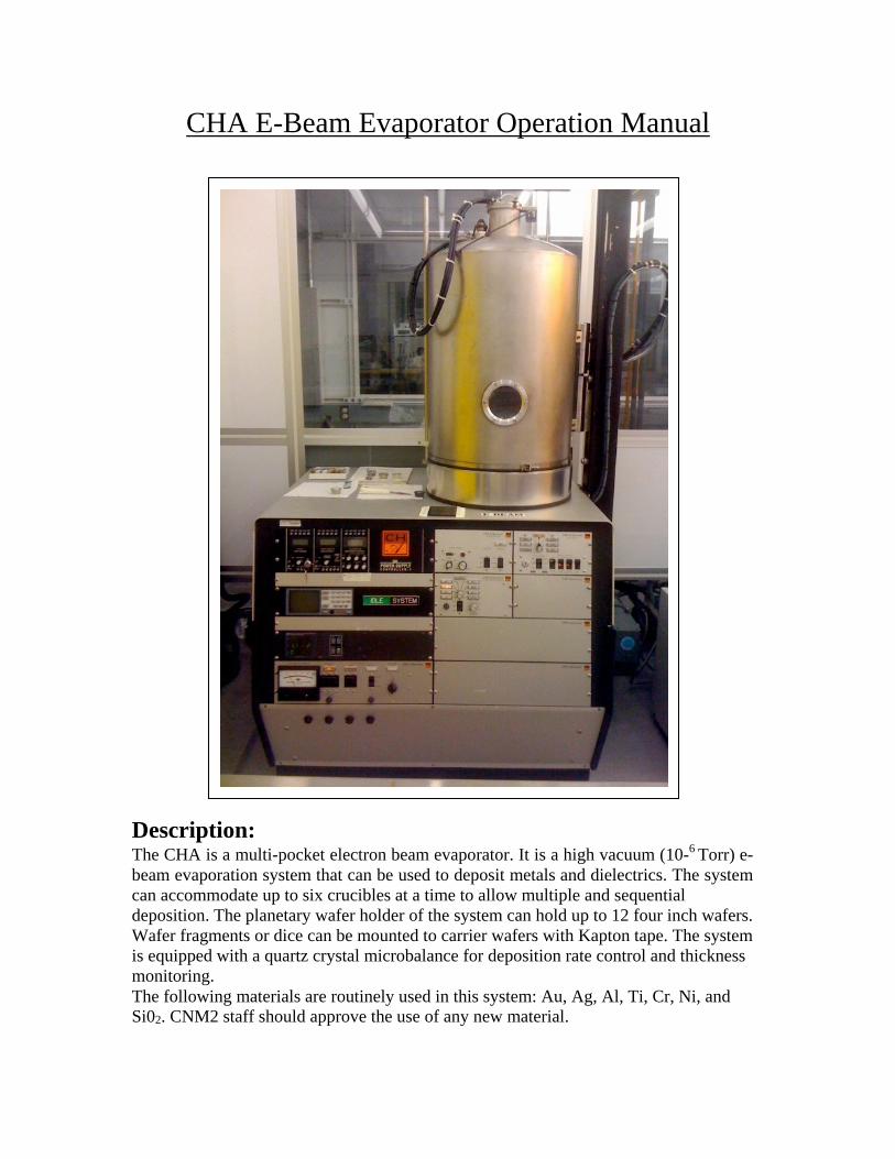
CHA E-Beam Evaporator Operation Manual
Description: The CHA is a multi-pocket electron beam evaporator. It is a high vacuum (10-6 Torr) e- beam evaporation system that can be used to deposit metals and dielectrics. The system can accommodate up to six crucibles at a time to allow multiple and sequential deposition. The planetary wafer holder of the system can hold up to 12 four inch wafers. Wafer fragments or dice can be mounted to carrier wafers with Kapton tape. The system is equipped with a quartz crystal microbalance for deposition rate control and thickness monitoring. The following materials are routinely used in this system: Au, Ag, Al, Ti, Cr, Ni, and Si02. CNM2 staff should approve the use of any new material.
Safety: 1. Before using this tool, users must be properly trained and certified by Lab Staff. 2. Only vacuum compatible materials are allowed in the system (Please contact
CNM2 staff if you are not sure about the materials vacuum compatibility). 3. Never touch anything inside the chamber with bare hands or contaminated gloves. 4. Do not touch any hot metals or hot crucibles, may cause severe burns. 5. Observe all safety precautions when you come into contact with dangerous
substances. 6. Stay away from moving parts especially when the chamber is rising and lowering.
Emergency Shut Off: If the machine malfunctions any time during the process, complete the following steps:
1. Turn OFF the high voltage supply. 2. Turn OFF the key. 3. Call CNM2 staff
a. Lab Phone 2-9831 b. Bob Prohaska 2-1094
System Operation
Initial System Checks:
1. Check the logbook to verify if the last entry was okay. 2. See Appendix A: Figure 1& 2 to get familiar with the switches and panel boards
of the system. 3. Chamber down and under vacuum. The pressure reading of IG1 or IG@ should be
approximately ~5E-6 Torr (see Appendix A: figure 3) Switch 4. Vacuum/Hoist switched to START/LOWER, the vacuum controller should
always be set to automatic (see Appendix A: figure 4) 5. Main power supply OFF (see Appendix A: figure 6) 6. Deposition rate controller OFF (see Appendix A: figure 2)
Preparing Chamber for Deposition
1. Turn OFF the ion gauge by pressing the IG1 and IG2 on the ion gauge controller (see Appendix A: figure 3)
2. Switch the Vacuum/Hoist switch to the VENT/RAISE position (see Appendix A: figure 4)
3. The Vent valve will automatically open, vent the chamber, and the hoist will raise the chamber. Wait about 1-2 minutes.
4. Check the chamber for any material particles. Wipe or vacuum the particles if necessary.
Load Evaporation Materials
1. During this step, the wafer holder planetary should be at the OFF position and at least one wafer holder should be removed from the system to get access to the crucibles.
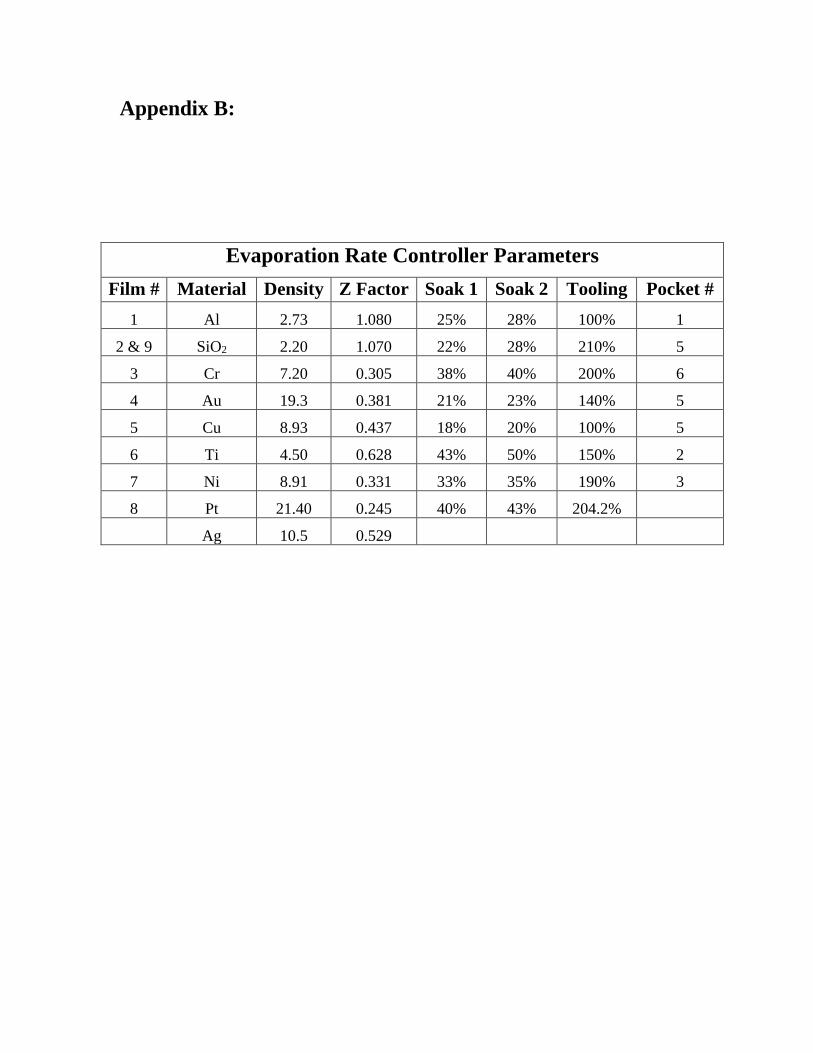
2. Open the shutter (see Appendix A: figure 1) 3. Set the pocket selector dial to the desired pocket number. The hearth will rotate
until the proper pocket is exposed. See the picture below to locate the dial (see Appendix A: figure 5).
4. Check if there is enough material to run the process and refill the crucible if necessary.
5. Place the material to be evaporated inside the pocket. (Aluminum and Titanium will always be in place). Make sure the pocket is clear of debris; use a vacuum cleaner if necessary. Pocket 1 is dedicated to Aluminum with 2% silicon; pocket 2 is dedicated to Titanium. All other materials must have a liner. DO NOT over fill the crucible. See picture 3.
6. Turn the shutter to the AUTO position. Load Substrate
1. Remove the planetary and load the wafers. a. Two ways:
i. Wafers are held flush with the planetary hemisphere for shadow masking processes such as lift-off (2 planetaries-12 wafer locations total) and
ii. Wafers are held at a 45° angle to the planetary hemisphere (1 planetary-6 locations total). Used for producing conformal coatings over surface features.
2. After replacing the planetary with the wafers, make sure that all items are clear of the chamber and planetary motion is free to rotate.
Chamber pump down
1. Switch the vacuum/hoist control to STANDBY/STOP, and then STOP/LOWER. The system will automatically lower the chamber, rough pump the chamber and then switch to hi-vac (see Appendix A: figure 4).
2. Note the time it takes the chamber to pump from roughing to hi-vac in the logbook.
3. Shortly after the system switches to high vacuum, turn ON the chamber ion gauge by pressing the IG2 button on the pressure gauge controller. When IG2 reads <5x10⁻⁶ Torr, evaporation may begin.
Preparing the Deposition rate controller
Deposition run parameters may be set while the chamber is pumping down. Definitions:
Film # - A film # represents a specific material. Each material requires a different set of deposition parameters.
Process - A process is a set of commands that directs the controller to deposit one or more films. Each process step consists of the mode, the film to be deposited, and the thickness of the film. In most cases, only one film is used.
Layer - Layer numbers represent the number of film layers in the process. In most cases a single deposition is done so there will only be one layer. The Sycon rate controller can be programmed with 9 different processes each containing up to 99 steps. It also has storage for up to 9 different film parameter sets. For more information see the Sycon controller manual.
Controller Setup for Deposition
I. Edit the process Note: Process 1 is programmed to deposit 5000A of Aluminum, film #1, and should not be changed. To locate the program boards see Appendix A figure 1.
1. Press MENU then 3. This places the controller in Process Review mode. 2. Press MENU and then the process number to edit (2-9) 3. Edit the process.
In most cases the process will consist of two steps. The first step specifies which film will be deposited and how much. The second step is the END. Assuming this is the case, use the down arrow to advance the cursor to the film column. Enter the desired film number (after the first key is pressed, the computer will ask for the security code). Then advance to the thickness column and enter the desired thickness in K.
4. Press MENU then MENU to return to the Runtime Display.
II. Activate the Process:
1. Press MENU then 2. You will be asked to enter the security code. 2. Type in the security code, press ENTER. 3. Type in the number of the process you wish to activate. This will activate the
process and return to the Runtime Display. The deposition rate controller is now programmed.
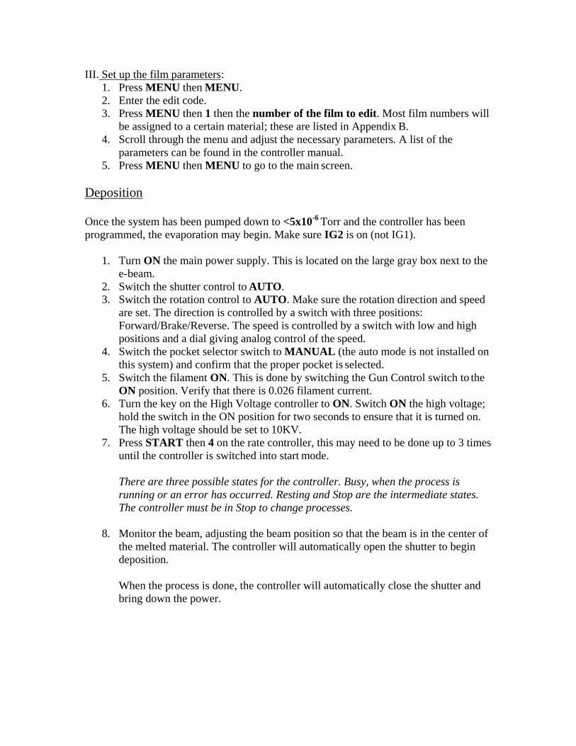
III. Set up the film parameters: 1. Press MENU then MENU. 2. Enter the edit code. 3. Press MENU then 1 then the number of the film to edit. Most film numbers will
be assigned to a certain material; these are listed in Appendix B. 4. Scroll through the menu and adjust the necessary parameters. A list of the
parameters can be found in the controller manual. 5. Press MENU then MENU to go to the main screen.
Deposition
Once the system has been pumped down to <5x10⁻⁶ Torr and the controller has been programmed, the evaporation may begin. Make sure IG2 is on (not IG1).
1. Turn ON the main power supply. This is located on the large gray box next to the
e-beam. 2. Switch the shutter control to AUTO. 3. Switch the rotation control to AUTO. Make sure the rotation direction and speed
are set. The direction is controlled by a switch with three positions: Forward/Brake/Reverse. The speed is controlled by a switch with low and high positions and a dial giving analog control of the speed.
4. Switch the pocket selector switch to MANUAL (the auto mode is not installed on this system) and confirm that the proper pocket is selected.
5. Switch the filament ON. This is done by switching the Gun Control switch to the ON position. Verify that there is 0.026 filament current.
6. Turn the key on the High Voltage controller to ON. Switch ON the high voltage; hold the switch in the ON position for two seconds to ensure that it is turned on. The high voltage should be set to 10KV.
7. Press START then 4 on the rate controller, this may need to be done up to 3 times until the controller is switched into start mode.
There are three possible states for the controller. Busy, when the process is running or an error has occurred. Resting and Stop are the intermediate states. The controller must be in Stop to change processes.
8. Monitor the beam, adjusting the beam position so that the beam is in the center of
the melted material. The controller will automatically open the shutter to begin deposition.
When the process is done, the controller will automatically close the shutter and bring down the power.
Unloading and Chamber Pump down
1. Allow 10-15 minutes for the target to cool down (Metals will cool faster than dielectrics).
2. Turn OFF the high voltage and turn the key to the OFF position 3. Turn OFF the Gun Control (filament current) 4. Turn OFF the power to the deposition control. 5. Turn OFF the Rotation switch 6. Turn OFF main power supply to the CHA controllers. 7. Turn OFF the IG2 gauge. 8. Switch the Vacuum/Hoist to STANDBY/STOP. Wait until the light on the
FORELINE switch comes on, and then switch the Vacuum/Hoist switch to OPEN. The chamber will now vent and automatically be raised.
9. Remove wafers, targets, etc. 10. CLOSE the Shutter. 11. Switch the Vacuum/Hoist to the START/LOWER position. 12. Place the system into idle. 13. Clean up the area.
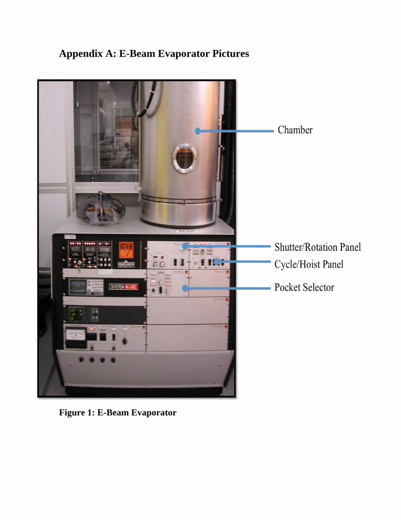
Appendix A: E-Beam Evaporator Pictures
Figure 1: E-Beam Evaporator
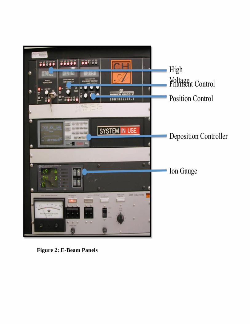
Figure 2: E-Beam Panels
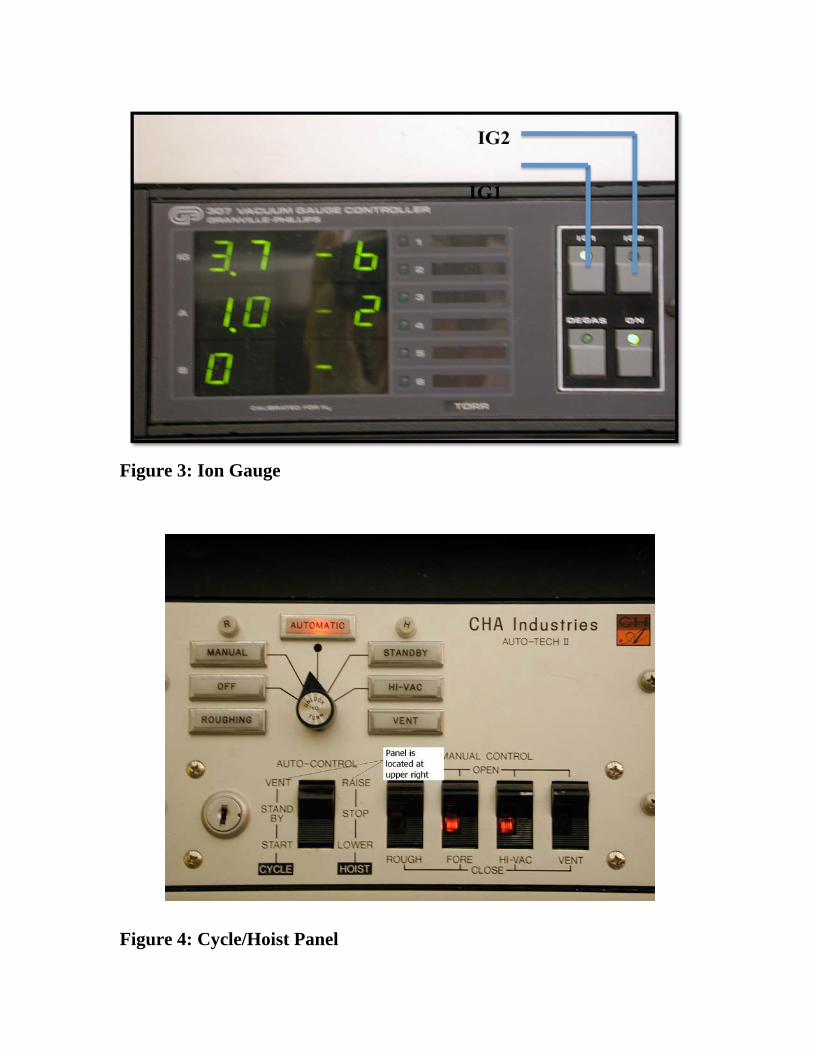
Figure 3: Ion Gauge
Figure 4: Cycle/Hoist Panel
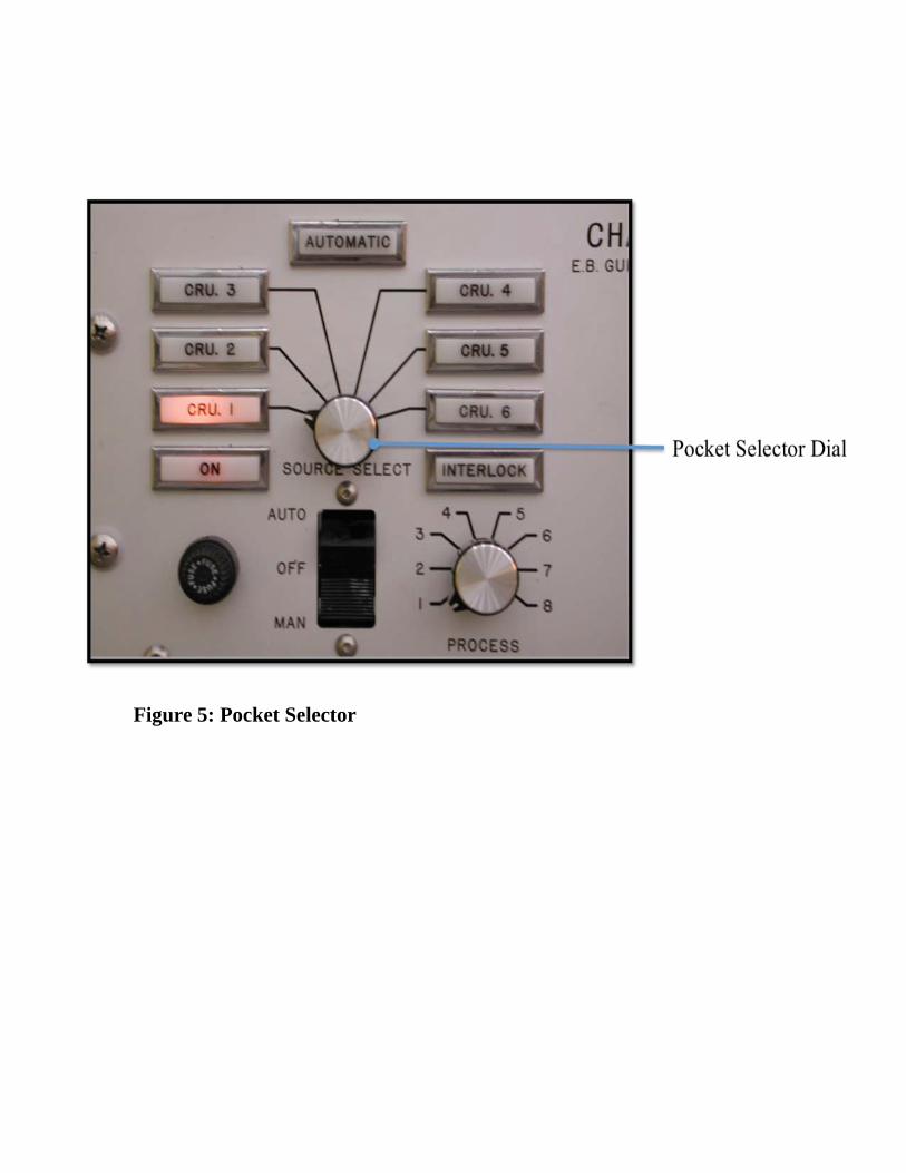
Figure 5: Pocket Selector
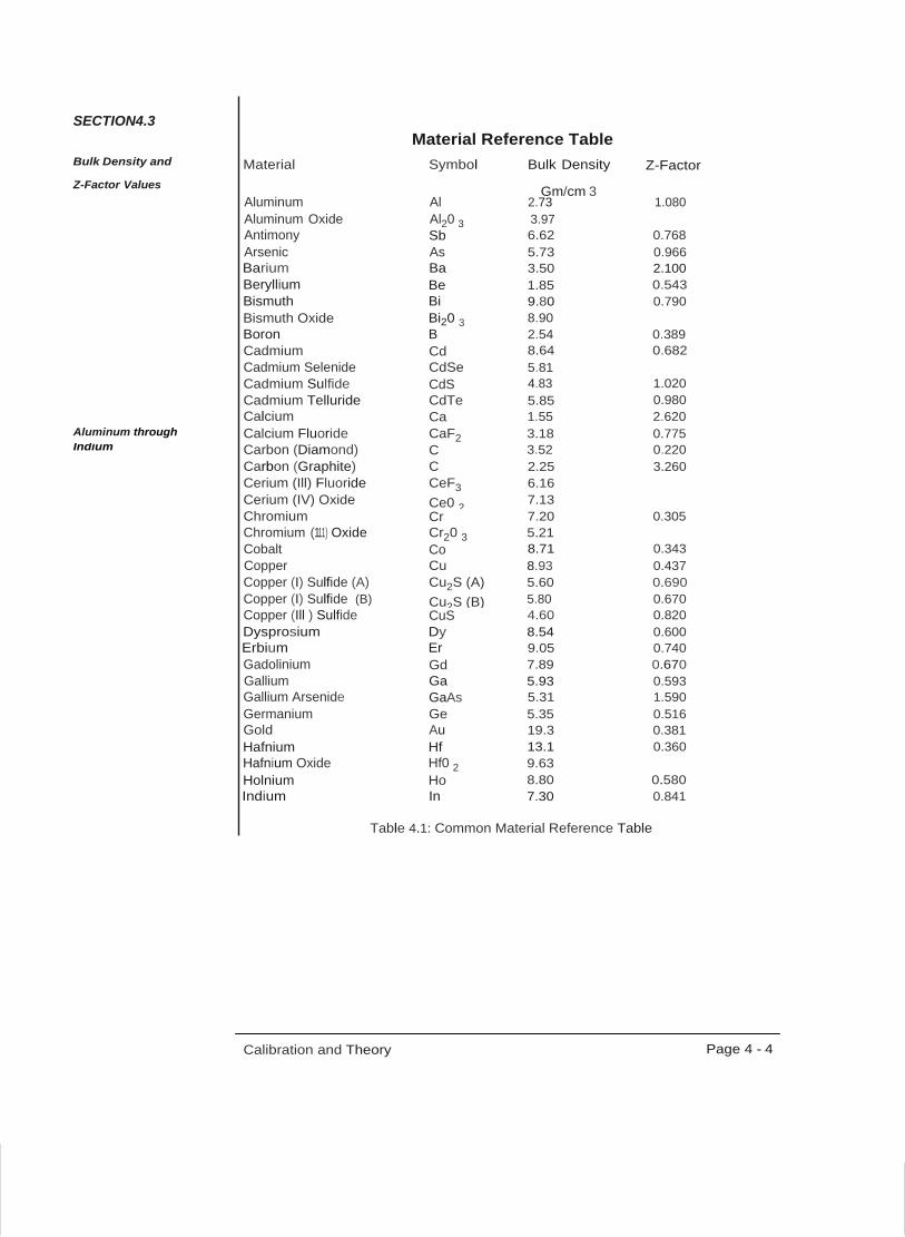
Appendix B:
Evaporation Rate Controller Parameters Film # Material Density Z Factor Soak 1 Soak 2 Tooling Pocket #
1 Al 2.73 1.080 25% 28% 100% 1
2 & 9 SiO2 2.20 1.070 22% 28% 210% 5
3 Cr 7.20 0.305 38% 40% 200% 6
4 Au 19.3 0.381 21% 23% 140% 5
5 Cu 8.93 0.437 18% 20% 100% 5
6 Ti 4.50 0.628 43% 50% 150% 2
7 Ni 8.91 0.331 33% 35% 190% 3
8 Pt 21.40 0.245 40% 43% 204.2%
Ag 10.5 0.529
SECTION4.3 Material Reference Table
Bulk Density and Material Symbol Bulk Density Z-Factor Z-Factor Values Gm/cm 3
Aluminum Al 2.73 1.080 Aluminum Oxide Al20 3 3.97
Calibration and Theory Page 4 - 4
Antimony Sb 6.62 0.768 Arsenic As 5.73 0.966 Barium Ba 3.50 2.100 Beryllium Be 1.85 0.543 Bismuth Bismuth Oxide
Bi Bi20 3
9.80 8.90
0.790
Boron B 2.54 0.389 Cadmium Cd 8.64 0.682 Cadmium Selenide CdSe 5.81 Cadmium Sulfide CdS 4.83 1.020 Cadmium Telluride CdTe 5.85 0.980 Calcium Ca 1.55 2.620 Aluminum through Calcium Fluoride CaF2 3.18 0.775 Indium Carbon (Diamond) C 3.52 0.220 Carbon (Graphite) C 2.25 3.260 Cerium (Ill) Fluoride CeF3 6.16 Cerium (IV) Oxide Ce0 2 7.13 Chromium
Chromium (111) Oxide Cr Cr20 3
7.20 5.21
0.305
Cobalt Co 8.71 0.343 Copper Cu 8.93 0.437 Copper (I) Sulfide (A) Cu2S (A) 5.60 0.690 Copper (I) Sulfide (B) Cu2S (B) 5.80 0.670 Copper (Ill ) Sulfide CuS 4.60 0.820 Dysprosium Dy 8.54 0.600 Erbium Er 9.05 0.740 Gadolinium Gd 7.89 0.670 Gallium Ga 5.93 0.593 Gallium Arsenide GaAs 5.31 1.590 Germanium Ge 5.35 0.516 Gold Au 19.3 0.381 Hafnium Hf 13.1 0.360 Hafnium Oxide Hf0 2 9.63 Holnium Ho 8.80 0.580 Indium In 7.30 0.841
Table 4.1: Common Material Reference Table
Palladium Pd 12.0 0.357 Platinum Pt 21.4 0.245 Potassium Chloride KCI 1.98 2.050 Rhenium Re 21.04 0.150 Rhodium Rh 12.41 0.210 Rubidium Rb 1.53 2.540 Samarium Sm 7.54 0.890 Scandium Sc 3.00 0.910 Selenium Se 4.82 0.864 Silicon Si 2.32 0.712 Silicon (II) Oxide SiO 2.13 0.870 Silicon Dioxide Si0 2 2.20 1.070 Silver Ag 10.5 0.529 Silver Bromide AgBr 6.47 1.180 Silver Chloride AgCI 5.56 1.320 Sodium Na 0.97 4.800 Sodium Chloride NaCl 2.17 1.570 Sulfur s 2.07 2.290 Tantalum Ta 16.6 0.262 Tantalum (IV) Oxide Ta20 5 8.20 0.300
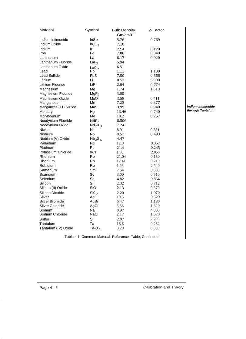
Table 4.1: Common Material Reference Table, Continued
Page 4 - 5 Calibration and Theory
Indium lntimonide through Tantalum
Material Symbol Bulk Density Z-Factor Gm/cm3 Indium lntimonide lnSb 5.76 0.769 Indium Oxide ln20 3 7.18 Iridium Ir 22.4 0.129 Iron Fe 7.86 0.349 Lanthanum La 6.17 0.920 Lanthanum Fluoride LaF3 5.94 Lanthanum Oxide La0 3 6.51 Lead Pb 11.3 1.130 Lead Sulfide PbS 7.50 0.566 Lithium Li 0.53 5.900 Lithium Fluoride LiF 2.64 0.774 Magnesium Mg 1.74 1.610 Magnesium Fluoride MgF2 3.00 Magnesium Oxide MgO 3.58 0.411 Manganese Mn 7.20 0.377 Manganese (11) Sulfide MnS 3.99 0.940 Mercury Hg 13.46 0.740 Molybdenum Mo 10.2 0.257 Neodynium Fluoride Neodynium Oxide
NdF3 Nd20 3
6.506 7.24
Nickel Ni 8.91 0.331 Niobium Nb 8.57 0.493 Niobium (V) Oxide Nb20 5 4.47
Material Symbol Bulk Density Z-Factor Gm/cm3
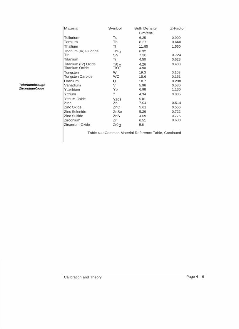
Tellurium Te 6.25 0.900 Terbium Tb 8.27 0.660 Thallium Tl 11 .85 1.550 Thorium (IV) Fluoride ThF4 6.32 Tin Sn 7.30 0.724 Titanium Ti 4.50 0.628 Titanium (IV) Oxide Ti0 2 4.26 0.400 Titanium Oxide TiO 4.90 Tungsten w 19 .3 0.163 Tungsten Carbide WC 15.6 0.151 Uranium u 18.7 0.238
Teluriumthrough Vanadium V 5.96 0.530 ZirconiumOxide Ytterbium Yb 6.98 1.130
Yttrium y 4.34 0.835 Yttrium Oxide Y203 5.01 Zinc Zn 7.04 0.514 Zinc Oxide ZnO 5.61 0.556 Zinc Selenide ZnSe 5.26 0.722 Zinc Sulfide ZnS 4.09 0.775 Zirconium Zr 6.51 0.600 Zirconium Oxide Zr0 2 5.6
Table 4.1: Common Material Reference Table, Continued
Calibration and Theory Page 4 - 6