Embed Size (px)
Citation preview

Chain & Attachments

TTable of Contentsable of Contents
2
4 . . . . . . . . . . . . . . . . . . . . . . . . . . . . . . . . . . . . . . . Warnings
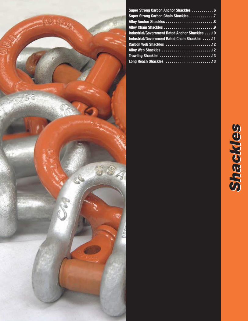
5-13 . . . . . . . . . . . . . . . . . . . . . . . . . . . . . . . . . . . . Shackles
14 . . . . . . . . . . . . . . . . . . . . . . . . . . . . . . . . . . . . . . Chain Comparison
15-30 . . . . . . . . . . . . . . . . . . . . . . . . . . . . . . . . . . . Herc-Alloy 1000
31-50 . . . . . . . . . . . . . . . . . . . . . . . . . . . . . . . . . . . Overhead Lifting
51-76 . . . . . . . . . . . . . . . . . . . . . . . . . . . . . . . . . . . Carbon Chain
77-89 . . . . . . . . . . . . . . . . . . . . . . . . . . . . . . . . . . . Specialty Chain
90-96 . . . . . . . . . . . . . . . . . . . . . . . . . . . . . . . . . . . Wire Rope Attachments
97-115 . . . . . . . . . . . . . . . . . . . . . . . . . . . . . . . . . . Below the Hook
116 . . . . . . . . . . . . . . . . . . . . . . . . . . . . . . . . . . . . . Steerman
117-119 . . . . . . . . . . . . . . . . . . . . . . . . . . . . . . . . . Index (full product listing)
Columbus McKinnon Corporation’s rich tradition of providing quality products and services tomeet the needs of users in a variety of industries around the globe continues with an expanded lineof chain and attachments by CM Rigging Products. Used by professional riggers, maintenanceworkers, plant engineers and safety specialists to lift, pull, and secure loads, the broad productoffering allows users to select the proper product for everyday use or for those challenging, uniqueapplications which arise during the course of a project. An integral part of the “CM Complete LiftingSystems,” chain and attachments come in a wide range of configurations and capacities.
The line of Herc-Alloy 1000 chain with its exceptional working load limits hasdeveloped a following in industries where strength to weight ratios of the chainare vital. Herc- Alloy 1000 has a 25% higher working load limit when comparedto its Grade 80 counterparts, and may allow a worker to lift using a smaller,lighter chain than has traditionally been used. Herc-Alloy 1000 chain is providedas a stand-alone product, but is normally part of a overhead lifting slingcontaining Grade 100 fittings such as hooks, Hammerlok coupling devices, andmaster links. The innovative Lodelok hooks that can be supplied as part ofoverhead lifting chain slings provide maximum security in a user-friendlyattachment.
The Super Strong Shackle is made from a special micro-alloy material, andprovides higher working load limits than traditional carbon shackles. Theseshackles are used extensively in construction activities, and are part of a broadoffering from the company’s extensive forging.

3
Camlok Lifting Clamps provide stability when lifting steel plates, aluminum,glass, or rails. Numerous configurations and styles are available such as gentlegrip clamps that will not harm the surfaces of the load, wide jaw clamps forspecial lifts, and horizontal lifting clamps used in pairs. Cady Lifters provides anextensive range of C-Hooks, spreader beams, and crane forks, and alsodevelops individual products to meet specific customer requests. Hoist ringsin forged and machined styles provide flexibility when lifting equipment andmachinery at various angles.
If load securement is the goal, then load binders from Dixie Industries fit thebill. Ratchet and lever styles, specialty binders, and binder chain assemblies invarious lengths provide over-the-road truckers with superior security. Varioustowing hooks and clusters are also an important product segment for Dixie,and the engineering group is consistently exploring unique opportunities fromcustomers.
Rounding out the product offering is a thorough line of industry-specificspecialty chain. From buoy chain to conveyor chain, CM Rigging Productsoffers one of the most extensive lines in the industry.
Although the broad product offering is one aspect of CM Rigging Products that provides separationfrom the competition, many additional services standout:
• A global network of authorized distributors provides inventory, technical support, serviceafter the sale, and consultation regarding specific needs.
• A thoroughly trained, knowledgeable sales force provides expertise on applications,regulations, training requirements, and product features and benefits.
• Customer service representatives address an array of issues related to shipments,product selection, specifications, and auxiliary items.
• Manufacturing facilities where testing exceeds the standards outlined by industryregulations.
• An engineering staff at manufacturing locations that works on developing uniquesolutions to opportunities.
• Training programs dedicated specifically to rigging products or broad-based to cover allaspects of lifting and positioning.
• The ONLY manufacturer of rigging products that is also a LEADER in the manufacturingand marketing of hoists, overhead cranes, and related products.
• More than 130 years of experience in providing products and programs that exceed theexpectations of customers.
• Some of the most recognized names in the material handling industry including thefollowing that are registered in the U.S. Patent and Trademark Office: Big Orange,Clevlok, CM, Cradle Grab, E-Z Pro, Hammerlok, Herc-Alloy, Lister, PiggyBack, Steerman.Additionally, the following are trademarks of Columbus McKinnon Corporation: Cady,Dixie, Lodelok, Pat-lok.
CM Rigging Products – an extensive mix of products, services, and support and a growingsegment of Columbus McKinnon Corporation.

4
WWararningningColumbus McKinnon Corporation assumes no responsibility for the misuse or misapplication of anyof its products. Products are provided with the express understanding that the purchaser and userare thoroughly familiar with the correct application and proper use of such products in rigging.
! !WARNINGImproper use or care of chain can result in loss of load and/or personal injury
To avoid injury:• Do not exceed the working load limit.• Always inspect chain before use for wear, damage, and elongation, Do not impact load or jerk
chain. Apply load slowly.• Protect chain from corrosion and high temperatures.• Use only alloy chain and attachments for overhead lifting.• Do not use twisted, knotted, or kinked chain.• Select the proper grade and size chain for the application.• Select attachments such as hooks to match the grade, size, and working load limit of the chain.• Be aware of the environment where chain and hardware are being used. Extreme temperatures
and corrosive media can affect the working load limit life of chain and hardware.
! !WARNINGImproper use of rigging attachments can result in bodily injury or property damage
To avoid injury:• Do not exceed the working load limit.• Do not tip load or use attachments in any manner for which they were not intended.• Do not shock or dynamic load.• Do not apply load to latches. Latches are to retain slack slings and chain only.• Select attachments to match the grade, size, and working load limit of the chain.• Do not use excessively worn or damaged attachments.• Do not use mechanical coupling links to repair alloy chains used for overhead lifting.• When using master rings or master links, do not use oversize crane hooks where the link does
not fit in the saddle of the hook. • When using shackles, do not side load. Centerline of the load must coincide with centerline of
shackle.• Do not replace pins or bolts with other than original equipment parts.• Use only forged carbon wire rope clips for critical or lifting applications.• Do not use malleable iron wire rope clips for critical or lifting applications. • Use wire rope clips in conjunction with wire rope thimbles.• When using shoulder eyebolts, always apply load in the plane of the eye.• When using shoulder eyebolts, make sure shoulder is at 90 degrees to axis of hole and seated.• When using hoist rings, verify full 360 degree seating and re-torque periodically.• Do not move unbalanced loads.• When using load binders, do not use a cheater bar or handle extension.• Do not operate a load binder while anyone is on the load.• Release lever type load binders with extreme care. Make sure everyone is clear of the load as
handle may whip suddenly.
For complete care, use, and inspection information, refer to the “CM Lifting, Pulling, & Binding Products Manual #PMC-10.
Shack
les
Shack
les
Super Strong Carbon Anchor Shackles . . . . . . . . . . . 6Super Strong Carbon Chain Shackles . . . . . . . . . . . . .7Alloy Anchor Shackles . . . . . . . . . . . . . . . . . . . . . . . . .8Alloy Chain Shackles . . . . . . . . . . . . . . . . . . . . . . . . . .9Industrial/Government Rated Anchor Shackles . . . .10Industrial/Government Rated Chain Shackles . . . . .11Carbon Web Shackles . . . . . . . . . . . . . . . . . . . . . . . .12Alloy Web Shackles . . . . . . . . . . . . . . . . . . . . . . . . . .12Trawling Shackles . . . . . . . . . . . . . . . . . . . . . . . . . . .13Long Reach Shackles . . . . . . . . . . . . . . . . . . . . . . . .13
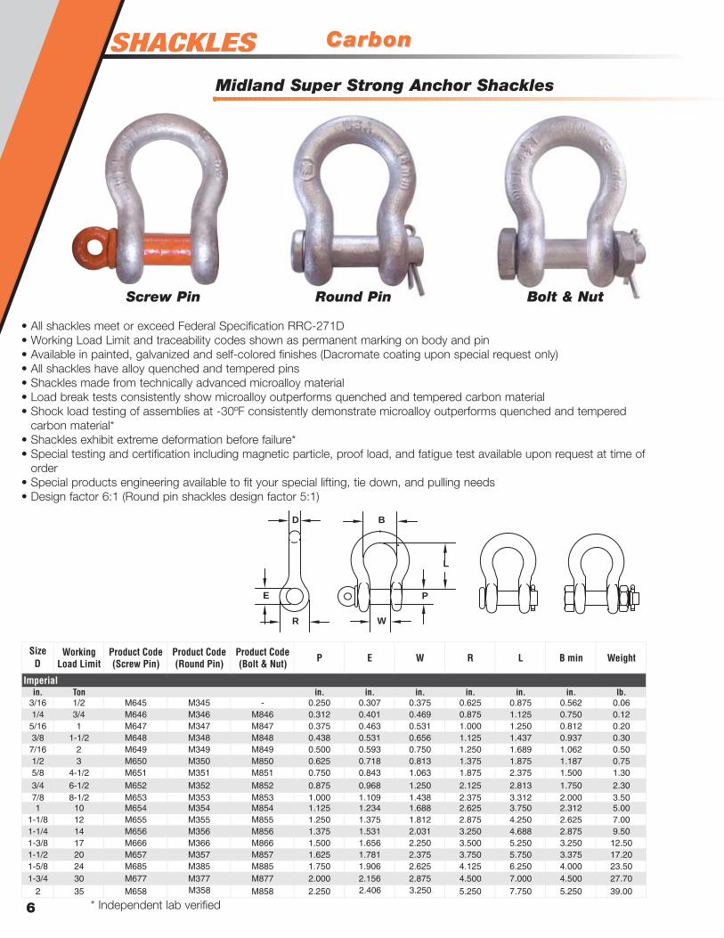
SHACKLES CarbonCarbon
Midland Super Strong Anchor Shackles
6
in. Ton in. in. in. in. in. in. lb.3/16 1/2 M645 M345 - 0.250 0.307 0.375 0.625 0.875 0.562 0.061/4 3/4 M646 M346 M846 0.312 0.401 0.469 0.875 1.125 0.750 0.12
5/16 1 M647 M347 M847 0.375 0.463 0.531 1.000 1.250 0.812 0.203/8 1-1/2 M648 M348 M848 0.438 0.531 0.656 1.125 1.437 0.937 0.30
7/16 2 M649 M349 M849 0.500 0.593 0.750 1.250 1.689 1.062 0.501/2 3 M650 M350 M850 0.625 0.718 0.813 1.375 1.875 1.187 0.755/8 4-1/2 M651 M351 M851 0.750 0.843 1.063 1.875 2.375 1.500 1.30
3/4 6-1/2 M652 M352 M852 0.875 0.968 1.250 2.125 2.813 1.750 2.307/8 8-1/2 M653 M353 M853 1.000 1.109 1.438 2.375 3.312 2.000 3.501 10 M654 M354 M854 1.125 1.234 1.688 2.625 3.750 2.312 5.00
1-1/8 12 M655 M355 M855 1.250 1.375 1.812 2.875 4.250 2.625 7.001-1/4 14 M656 M356 M856 1.375 1.531 2.031 3.250 4.688 2.875 9.501-3/8 17 M666 M366 M866 1.500 1.656 2.250 3.500 5.250 3.250 12.501-1/2 20 M657 M357 M857 1.625 1.781 2.375 3.750 5.750 3.375 17.201-5/8 24 M685 M385 M885 1.750 1.906 2.625 4.125 6.250 4.000 23.501-3/4 30 M677 M377 M877 2.000 2.156 2.875 4.500 7.000 4.500 27.70
2 35 M658 M358 M858 2.250 2.406 3.250 5.250 7.750 5.250 39.00
Working Load Limit Weight
Imperial
P E W R LSize
B minProduct Code (Screw Pin)
Product Code (Round Pin)
Product Code (Bolt & Nut)D
• All shackles meet or exceed Federal Specification RRC-271D• Working Load Limit and traceability codes shown as permanent marking on body and pin• Available in painted, galvanized and self-colored finishes (Dacromate coating upon special request only)• All shackles have alloy quenched and tempered pins• Shackles made from technically advanced microalloy material• Load break tests consistently show microalloy outperforms quenched and tempered carbon material• Shock load testing of assemblies at -30ºF consistently demonstrate microalloy outperforms quenched and tempered
carbon material*• Shackles exhibit extreme deformation before failure*• Special testing and certification including magnetic particle, proof load, and fatigue test available upon request at time of
order• Special products engineering available to fit your special lifting, tie down, and pulling needs• Design factor 6:1 (Round pin shackles design factor 5:1)
E
D B
R W
L
P
Screw Pin Round Pin Bolt & Nut
* Independent lab verified

CarbonCarbon
Midland Super Strong Chain Shackles
7
Sha
ckle
sin. Ton in. in. in. in. in. lb.1/4 3/4 M746 M546 M946 0.312 0.401 0.469 0.875 0.875 0.12
5/16 1 M747 M547 M947 0.375 0.463 0.531 1.000 1.031 0.203/8 1-1/2 M748 M548 M948 0.438 0.531 0.656 1.125 1.250 0.30
7/16 2 M749 M549 M949 0.500 0.593 0.750 1.250 1.437 0.501/2 3 M750 M550 M950 0.625 0.718 0.813 1.375 1.625 0.755/8 4-1/2 M751 M551 M951 0.750 0.843 1.063 1.875 2.000 1.30
3/4 6-1/2 M752 M552 M952 0.875 0.968 1.250 2.125 2.375 2.307/8 8-1/2 M753 M553 M953 1.000 1.109 1.438 2.375 2.812 3.501 10 M754 M554 M954 1.125 1.234 1.688 2.625 3.188 5.00
1-1/8 12 M755 M555 M955 1.250 1.375 1.812 2.875 3.562 7.001-1/4 14 M756 M556 M956 1.375 1.531 2.031 3.250 3.938 9.501-3/8 17 M766 M566 M966 1.500 1.656 2.250 3.500 4.438 12.501-1/2 20 M757 M557 M957 1.625 1.781 2.375 3.750 4.875 17.201-5/8 24 M785 M585 M985 1.750 1.906 2.625 4.125 5.250 23.501-3/4 30 M777 M577 M977 2.000 2.156 2.875 4.500 5.750 27.70
2 35 M758 M558 M958 2.250 2.406 3.250 5.250 6.750 39.00
Imperial
Product Code (Screw Pin)
Product Code (Round Pin)
Product Code (Bolt & Nut)
Working Load Limit P E W WeightLR
SizeD
• All shackles meet or exceed Federal Specification RRC-271D• Working Load Limit and traceability codes shown as permanent marking on body and pin• Available in painted, galvanized and self-colored finishes (Dacromate coating upon special request only)• All shackles have alloy quenched and tempered pins• Shackles made from technically advanced microalloy material• Load break tests consistently show microalloy outperforms quenched and tempered carbon material• Shock load testing of assemblies at -30ºF consistently demonstrate microalloy outperforms quenched and tempered
carbon material*• Shackles exhibit extreme deformation before failure*• Special testing and certification including magnetic particle, proof load, and fatigue test available upon request at time of
order• Special products engineering available to fit your special lifting, tie down, and pulling needs• Design factor 6:1 (Round pin shackles design factor 5:1)
E
D
R W
L
P
* Independent lab verified
Screw Pin Round Pin Bolt & Nut

SHACKLES AlloyAlloy
Midland Anchor Shackles
8
• All shackles meet or exceed Federal Specification RRC-271D• Working Load Limit and traceability codes shown as permanent marking on body and pin• Available in painted, galvanized and self-colored finishes (Dacromate coating upon special request only)• All shackles have alloy quenched and tempered pins• Shackles exhibit extreme deformation before failure*• Special testing and certification including magnetic particle, proof load, and fatigue test available upon request
at time of order• Special products engineering available to fit your special lifting, tie down, and pulling needs• Design factor 5:1
E
D B
R W
L
P
in. Ton in. in. in. in. in. in. lb.3/8 2 M648A - M848A 0.438 0.531 0.656 1.125 1.437 0.937 0.30
7/16 2.6 M649A M349A M849A 0.500 0.593 0.750 1.250 1.689 1.062 0.501/2 3.3 M650A M350A M850A 0.625 0.718 0.813 1.375 1.875 1.187 0.755/8 5 M651A M351A M851A 0.750 0.843 1.063 1.875 2.375 1.500 1.303/4 7 M652A M352A M852A 0.875 0.968 1.250 2.125 2.813 1.750 2.307/8 9.5 M653A M353A M853A 1.000 1.109 1.438 2.375 3.312 2.000 3.501 12.5 M654A M354A M854A 1.125 1.234 1.688 2.625 3.750 2.312 5.00
1-1/8 15 M655A M355A M855A 1.250 1.375 1.812 2.875 4.250 2.625 7.001-1/4 18 M656A M356A M856A 1.375 1.531 2.031 3.250 4.688 2.875 9.501-3/8 21 M666A M366A M866A 1.500 1.656 2.250 3.500 5.250 3.250 12.501-1/2 25 M657A M357A - 1.625 1.781 2.375 3.750 5.750 3.375 17.201-1/2 30 - - M857A 1.625 1.781 2.375 3.750 5.750 3.375 17.201-5/8 29 M685A M385A - 1.750 1.906 2.625 4.125 6.250 4.000 23.501-5/8 35 - - M885A 1.750 1.906 2.625 4.125 6.250 4.000 23.501-3/4 34 M677A M377A - 2.000 2.156 2.875 4.500 7.000 4.500 27.701-3/4 40 - - M877A 2.000 2.156 2.875 4.500 7.000 4.500 27.70
2 43 M658A M358A - 2.250 2.406 3.250 5.250 7.750 5.250 39.002 50 - - M858A 2.250 2.406 3.250 5.250 7.750 5.250 39.00
2-1/2 85 - - MC860AG 2.750 2.906 4.125 6.250 10.500 6.750 90.503 120 - - MC862AG 3.250 3.406 5.000 6.750 13.000 7.375 137.00
B minProduct Code (Screw Pin)
Product Code (Round Pin)
Product Code (Bolt & Nut) Weight
Imperial
P E W R LSize Working
Load LimitD
Screw Pin Round Pin Bolt & Nut
* Independent lab verified
AlloyAlloy
Midland Chain Shackles
9
Sha
ckle
s
• All shackles meet or exceed Federal Specification RRC-271D• Working Load Limit and traceability codes shown as permanent marking on body and pin• Available in painted, galvanized and self-colored finishes (Dacromate coating upon special request only)• All shackles have alloy quenched and tempered pins• Shackles exhibit extreme deformation before failure*• Special testing and certification including magnetic particle, proof load, and fatigue test available upon request at
time of order• Special products engineering available to fit your special lifting, tie down, and pulling needs• Design factor 5:1
E
D
R W
L
P
in. Ton in. in. in. in. in. lb.3/8 2 M748A - M948A 0.438 0.531 0.656 1.125 1.250 0.25
7/16 2.6 M749A - M949A 0.500 0.593 0.750 1.250 1.500 0.401/2 3.3 M750A M550A M950A 0.625 0.718 0.813 1.375 1.688 0.755/8 5 M751A M551A M951A 0.750 0.843 1.063 1.875 2.000 1.303/4 7 M752A M552A M952A 0.875 0.968 1.250 2.125 2.375 2.307/8 9.5 M753A M553A M953A 1.000 1.109 1.438 2.375 3.125 3.501 12.5 M754A M554A M954A 1.125 1.234 1.688 2.625 3.188 5.00
1-1/8 15 M755A M555A M955A 1.250 1.375 1.812 2.875 3.560 7.001-1/4 18 M756A M556A M956A 1.375 1.531 2.031 3.250 3.940 9.501-3/8 21 M766A M566A M966A 1.500 1.656 2.250 3.500 4.438 12.501-1/2 25 M757A M557A - 1.625 1.781 2.375 3.750 4.875 17.201-1/2 30 - - M957A 1.625 1.781 2.375 3.750 4.875 17.201-5/8 29 M785A M585A - 1.750 1.906 2.625 4.125 5.250 23.501-5/8 35 - - M985A 1.750 1.906 2.625 4.125 5.250 23.501-3/4 34 M777A M577A - 2.000 2.156 2.875 4.500 5.750 27.701-3/4 40 - - M977A 2.000 2.156 2.875 4.500 5.750 27.70
2 43 M758A M558A - 2.250 2.406 3.250 5.250 6.750 39.002 50 - - M958A 2.250 2.406 3.250 5.250 6.750 39.00
Imperial
WeightP E WProduct Code (Screw Pin)
Product Code (Round Pin)
Product Code (Bolt & Nut)
Working Load Limit R L
SizeD
* Independent lab verified
Screw Pin Round Pin Bolt & Nut

SHACKLES Industrial / GoverIndustrial / Government Ratednment Rated
Midland Carbon Anchor Shackles
10
in. Ton in. in. in. in. in. in. lb.3/16 1/3 MC645G MC345G - 0.250 0.307 0.375 0.625 0.875 0.562 0.061/4 1/2 MC646G MC346G MC846G 0.312 0.401 0.469 0.875 1.125 0.750 0.12
5/16 3/4 MC647G MC347G MC847G 0.375 0.463 0.531 1.000 1.250 0.812 0.203/8 1 MC648G MC348G MC848G 0.438 0.531 0.656 1.125 1.437 0.937 0.30
7/16 1-1/2 MC649G MC349G MC849G 0.500 0.593 0.750 1.250 1.689 1.062 0.501/2 2 MC650G MC350G MC850G 0.625 0.718 0.813 1.375 1.875 1.187 0.755/8 3-1/4 MC651G MC351G MC851G 0.750 0.843 1.063 1.875 2.375 1.500 1.30
3/4 4-3/4 MC652G MC352G MC852G 0.875 0.968 1.250 2.125 2.813 1.750 2.307/8 6-1/2 MC653G MC353G MC853G 1.000 1.109 1.438 2.375 3.312 2.000 3.501 8-1/2 MC654G MC354G MC854G 1.125 1.234 1.688 2.625 3.750 2.312 5.00
1-1/8 9-1/2 MC655G MC355G MC855G 1.250 1.375 1.812 2.875 4.250 2.625 7.001-1/4 12 MC656G MC356G MC856G 1.375 1.531 2.031 3.250 4.688 2.875 9.501-3/8 13-1/2 MC666G MC366G MC866G 1.500 1.656 2.250 3.500 5.250 3.250 12.501-1/2 17 MC657G MC357G MC857G 1.625 1.781 2.375 3.750 5.750 3.375 17.201-5/8 20 MC685G MC385G MC885G 1.750 1.906 2.625 4.125 6.250 4.000 23.501-3/4 25 MC677G MC377G MC877G 2.000 2.156 2.875 4.500 7.000 4.500 27.70
2 35 M658G M358G M858G 2.250 2.406 3.250 5.250 7.750 5.250 39.00
Working Load Limit B minProduct Code
(Screw Pin)Product Code (Round Pin)
Product Code (Bolt & Nut) Weight
Imperial
P E W R LSize
D
MC860G 2.750 2.905 4.125 6.250 10.500 6.750 90.502-1/2 55 - -
• These shackles meet requirements of Federal Specification RR-C-271D Amendment 1• All shackle pins are forged from alloy steel, heat treated and tempered to give greater strength• All shackles are marked with size (inches and millimeters) and working load limit in tons• Ultimate strength equals 5 times working load limit• All bolt, nut & cotter shackles have thread protected ends• Galvanized per ASTM A153• Standard industry tolerances apply• Design factor 5:1
E
D B
R W
L
P
Screw Pin Round Pin Bolt & Nut
Industrial / GoverIndustrial / Government Ratednment Rated
Midland Carbon Chain Shackles
11
Sha
ckle
sin. Ton in. in. in. in. in. lb.1/4 1/2 MC746G MC546G MC946G 0.312 0.401 0.469 0.875 0.875
5/16 3/4 MC747G MC547G MC947G 0.375 0.463 0.531 1.000 1.0313/8 1 MC748G MC548G MC948G 0.438 0.531 0.656 1.125 1.250
7/16 1-1/2 MC749G MC549G MC949G 0.500 0.593 0.750 1.250 1.4371/2 2 MC750G MC550G MC950G 0.625 0.718 0.813 1.375 1.6255/8 3-1/4 MC751G MC551G MC951G 0.750 0.843 1.063 1.875 2.000
3/4 4-3/4 MC752G MC552G MC952G 0.875 0.968 1.250 2.125 2.3757/8 6-1/2 MC753G MC553G MC953G 1.000 1.109 1.438 2.375 2.8121 8-1/2 MC754G MC554G MC954G 1.125 1.234 1.688 2.625 3.188
1-1/8 9-1/2 MC755G MC555G MC955G 1.250 1.375 1.812 2.875 3.5621-1/4 12 MC756G MC556G MC956G 1.375 1.531 2.031 3.250 3.9381-3/8 13-1/2 MC766G MC566G MC966G 1.500 1.656 2.250 3.500 4.4381-1/2 17 MC757G MC557G MC957G 1.625 1.781 2.375 3.750 4.8751-5/8 20 MC785G MC585G MC985G 1.750 1.906 2.625 4.125 5.2501-3/4 25 MC777G MC577G MC977G 2.000 2.156 2.875 4.500 5.750
2 35 M758G M558G M958G 2.250 2.406 3.250 5.250 6.750
P E WProduct Code (Screw Pin)
Product Code (Round Pin)
Product Code (Bolt & Nut)
Working Load Limit
Imperial
R LSize
Weight
0.250.400.751.302.303.505.00
7.009.5012.5017.2023.5027.7039.00
0.110.17
D
• Shackles meet or exceed Federal Specification RRC-271D • Working Load Limit and traceability codes shown as permanent marking on body and pin• Available in painted, galvanized and self-colored finishes (Dacromate coating upon special request only)• Special products engineering available to fit your special lifting, tie down, and pulling needs• Design factor 5:1
E
D
R W
L
P
Screw Pin Round Pin Bolt & Nut

SHACKLES
Alloy Web Sling Shackle
WWeb Shackleseb Shackles
Carbon Web Sling Shackle
12
lb. in. in. in. in. in. lb.M702 2X702 65930 8,050 0.75 0.63 2.25 2.00 1.63 1.70M703 2X703 65930 13,050 0.88 0.75 3.25 3.00 1.88 2.86M704 2X704 65930 10,800 0.88 0.75 3.75 4.00 1.88 3.15M705 2X705 65934 18,000 1.00 0.88 4.25 5.00 2.13 4.75M706 2X706 65934 18,000 1.13 1.00 4.75 6.00 2.38 6.75
M706H 2X706H 65934 23,850 1.25 1.13 4.75 6.00 2.63 9.80
P D LPin Number W RProduct Code
Imperial
Working Load Limit WeightLinch Pin
Number
lb. in. in. in. in. in. lb.M703A 2X8703A 65930 13,050 0.88 0.75 3.25 3.00 1.88 3.01M704A 2X8704A 65930 14,500 0.88 0.75 3.75 4.00 1.88 3.16M705A 2X8705A 65934 19,000 1.00 1.00 4.25 5.00 2.38 6.04M706A 2X8706A 65934 22,500 1.13 1.13 4.75 6.00 2.63 9.02
WeightLinch Pin Number
Imperial
P D LPin Number W RProduct Code
Working Load Limit
D
RW
P
L
D
R W
P
L
• Web Sling Shackles can beused on web slings from 3 to6 inches in width
• Utilize a bolt and nut withlinch style pin to secure theassembly in place
• All shackles are galvanizedfor longer life
• Marked with working loadlimit (WLL) and size
• Finish: hot dip galvanized• Klik pin (zinc plated) as shown
furnished as standard-cotter orhair pin can be furnished onspecial order
• Shackle body: carbon steel,heat treated
• Shackle pin: alloy steel, heattreated
• Tolerances: 11/32" unlessotherwise indicated
• Design ultimate strength equals4 times the working load limit

TTrawling & Long Reach Shacklesrawling & Long Reach Shackles
Midland Long Reach Shackles
Midland Trawling Shackle
13
Sha
ckle
s
R
D
K
W
OL
P
lb. in. in. in. in. in. in. in. lb.M449 4,000 0.438 0.500 0.719 1.500 2.750 1.125 1.906 0.43M450 6,000 0.500 0.625 0.813 1.688 3.125 1.250 2.063 0.60M451 9,000 6.250 0.750 1.063 2.000 3.780 1.500 2.625 1.30M452 13,000 0.750 0.875 1.250 2.375 4.530 1.875 3.125 2.20M453 17,000 0.875 1.000 1.438 2.812 5.750 2.125 3.625 3.00M454 20,000 1.000 1.125 1.688 3.188 5.938 2.375 4.438 4.70
Imperial
D P W L OProduct Code WeightR KWorking Load Limit
L
P
W
D
G DIA
Self Colored Painted Self Colored Painted
lb. lb. lb. in. in. in. in. in.7,000 M7151 M7151P 1.80 M9151 M9151P 1.95 0.75 0.63 4.00 2.25 1.5710,000 M7152 M7152P 2.72 M9152 M9152P 3.21 0.88 0.75 4.56 2.75 1.8119,000 M7154 M7154P 5.86 M9154 M9154P 6.31 1.00 1.00 5.50 3.25 2.3828,000 M7156 M7156P 11.90 M9156 M9156P 12.90 1.38 1.25 6.25 3.88 3.0634,000 M7157 M7157P 19.60 M9157 M9157P 20.70 1.63 1.50 7.00 4.50 3.5050,000 M7177 M7177P 30.70 M9177 M9177P 33.30 2.00 1.75 8.00 5.25 4.00
Imperial
Weight P D LScrew Pin Product Code Bolt Type Product Code
Weight W GWorking Load Limit
• Alloy Steel• Load Rated• WLL forged on body• Meets the requirements of
ASME B30.26 • Design factor of 5:1• Offered in self-colored or
orange urethane finish
• Heat treated bodies• Heat treated alloy pins• Square head pins for
convenience in wrenchtightening and loosening
• Proof load 2.2 times workingload limit
• Ultimate strength 6 timesworking load limit
• Painted orange
Load rated trawling chain shackles are used for various applications, such as on trawl doors, the rigging of nets,and areas where critical loads are applied.

Chain ComparisonChain Comparison
14
CM offers a wide range of welded chains. All chains meet or exceed requirements of NACM & ASTM standards. All chain isproof tested to insure you get the highest quality chain in the market. Listed below you will find a summary of chainspecifications, which can be used as a comparison when selecting the chain for your application. Only Herc-Alloy 1000 orHerc-Alloy 800 chain should be used for overhead lifting.
Chain SizeWire
Diameter Nominal
Inside Length Nominal
Inside Width Nominal
Weight Per 100 ft.
Working Load Limit
in. in. in. in. lb. lb.7/32 0.218 0.676 0.312 44.3 2,7009/32 0.281 0.883 0.395 72.9 4,3003/8 0.394 1.247 0.574 144.0 8,8001/2 0.512 1.559 0.734 246.0 15,0005/8 0.630 1.916 0.855 370.0 22,6003/4 0.787 2.397 1.070 577.0 35,300
in. in. in. in. lb. lb.7/32 0.218 0.676 0.312 44.3 2,1009/32 0.281 0.883 0.395 72.9 3,5005/16 0.315 1.019 0.455 90.9 4,5003/8 0.394 1.247 0.574 144.0 7,1001/2 0.512 1.440 0.734 255.0 12,0005/8 0.630 1.777 0.855 382.3 18,1003/4 0.787 2.234 1.070 595.0 28,3007/8 0.875 2.250 1.137 776.0 34,2001 1.000 3.070 1.490 939.0 47,700
1-1/4 1.250 3.920 1.740 1,420.0 72,300
in. in. in. in. lb. lb.1/4 0.281 0.840 0.470 76.4 3,150
5/16 0.327 0.980 0.460 100.5 4,7005/16 0.327 1.100 0.500 96.9 4,7003/8 0.406 1.140 0.540 158.0 6,6003/8 0.394 1.375 0.600 139.0 6,600
7/16 0.468 1.325 0.620 209.0 8,7501/2 0.531 1.559 0.734 267.0 11,300
in. in. in. in. lb. lb.1/4 0.270 1.220 0.460 60.0 2,600
5/16 0.327 1.100 0.500 98.1 3,9003/8 0.386 1.370 0.600 133.0 5,4001/2 0.500 1.730 0.810 227.0 9,2005/8 0.625 1.916 0.855 363.0 13,0003/4 0.781 2.397 1.070 568.0 20,200
in. in. in. in. lb. lb.3/16 0.213 0.970 0.360 37.3 8001/4 0.270 1.220 0.460 60.1 1,300
5/16 0.309 1.220 0.460 81.2 1,9003/8 0.386 1.370 0.600 132.8 2,6501/2 0.512 1.730 0.810 245.3 4,5005/8 0.625 1.916 0.855 363.0 6,9003/4 0.781 2.397 1.070 568.0 10,600
Transport (Grade 70)
High Test (Grade 43)
Proof Coil (Grade 30)
Herc-Alloy 1000 (Grade 100)
Herc-Alloy 800 (Grade 80)
Herc
-Alloy
1000
Herc
-Alloy
1000
Care, Use & Inspection . . . . . . . . . . . . . . . . . . . . . . . 16Herc-Alloy 1000 Chain . . . . . . . . . . . . . . . . . . . . . . . .17Herc-Alloy 1000 Slings . . . . . . . . . . . . . . . . . . . . .18-19Herc-Alloy 1000 Components . . . . . . . . . . . . . . .20-21Master Link . . . . . . . . . . . . . . . . . . . . . . . . . . . . . . . .22Sub-Assembly . . . . . . . . . . . . . . . . . . . . . . . . . . . . . .22Pear Shape Master Link . . . . . . . . . . . . . . . . . . . . . .23Hammerlok . . . . . . . . . . . . . . . . . . . . . . . . . . . . . . . . .23Chain Shortener . . . . . . . . . . . . . . . . . . . . . . . . . . . . .24Rigging Hook . . . . . . . . . . . . . . . . . . . . . . . . . . . . . . .24Clevlok Sling Hook . . . . . . . . . . . . . . . . . . . . . . . . . . .25Eye Sling Hook . . . . . . . . . . . . . . . . . . . . . . . . . . . . . .25Clevlok Cradle Grab Hook . . . . . . . . . . . . . . . . . . . . .26Eye Cradle Grab Hook . . . . . . . . . . . . . . . . . . . . . . . .26Clevlok Foundry Hook . . . . . . . . . . . . . . . . . . . . . . . .27Eye Foundry Hook . . . . . . . . . . . . . . . . . . . . . . . . . . .27Web-Hammerlok Hook . . . . . . . . . . . . . . . . . . . . . . . .28Web-Weblok Hook . . . . . . . . . . . . . . . . . . . . . . . . . . .28Clevlok Style Lodelok Hook . . . . . . . . . . . . . . . . . . . .29Eye Style Lodelok Hook . . . . . . . . . . . . . . . . . . . . . . .29Swivel Style Lodelok Hook . . . . . . . . . . . . . . . . . . . .30

® CarCare, Use & Inspectione, Use & Inspection
16
The life and strength of Herc-Alloy 1000 chain slings depend on proper inspection, maintenance and use. For additional information, refer to ASME B30.9 and OSHA 1910.184.
CareChain requires careful storage and regular maintenance. • Store chains on an A frame in a clean, dry place.• To avoid corrosion, oil chains before prolonged storage.• Do not heat Herc-Alloy 1000 chain; this will alter its
thermal treatment.
UseTo protect both operators and materials, observe theseprecautions when using chain slings:
• Before use, inspect chain and attachments following the instructions under “Inspection” below.
• Do not exceed working load limit. Any of the factors listed here can reduce the load the chain will hold:
- Acceleration in rate of load application can produce dangerous overloads.
- Variations in the angle of the load to the sling, as the angle decreases, the working load of the sling will increase.
- Twisting, knotting or kinking, subjects links to unusual loading, decreasing the working load of the sling.
- Use for purposes other than those for which slings are intended, can reduce the working load of the sling.
• Free chain of all twists, knots and kinks.• Center load in hook(s); hook latch must not support load.• Avoid sudden jerks when lifting or lowering load.• Balance all loads; avoid tipping of loads.• Use pads around sharp corners.• Do not drop load on chains.• Match the size and working load limits of attachments such
as hooks and rings to the size and working load limits of the chain.
• For overhead lifting, use only alloy chain and attachments.
InspectionIt is important both to inspect chain slings regularly and to keep arecord of all chain inspections. Follow this guide for such aninspection system.
• Before inspecting, clean chain with a non-acid/non-caustic solvent so that marks, nicks, wear and other defects are visible.
• Inspect each link for these conditions:- Twists and bends.- Nicks or gouges.- Excessive wear at bearing points
• Stretch• Distorted or damaged master links, coupling links or
attachments, especially spread in throat opening of hooks.• Mark plainly with paint each link or attachment showing
any of the conditions listed here to indicate rejection; remove from service until properly repaired.
Wear Allowances of Herc-Alloy1000 ChainMeasure cross section atlink ends to determinewear. If chain is worn toless than the minimumallowable thickness,remove from service.
CM Chain Inspection ProgramsCM provides chain users with a wide range of informativematerials and instructive programs on chain and chaininspection. Our colorful chain safety poster/chart and our fact-filled booklet, “CM Lifting, Pulling & Binding Products ManualPMC-10,” are available on request.
Use of Chain & Components UnderExtreme Temperature ConditionsWhen the chain itself is subjected to temperatures shownhere, working load limits should be reduced as indicated.
The identification tag found on each chain sling contains thisinformation:
• Grade • Size • Reach • Serial Number • Number of Legs • Working Load Limit (at a specific angle of lift)
T
in. mm in. mm7/32 5.5 0.189 4.89/32 7.0 0.239 6.13/8 10.0 0.342 8.71/2 13.0 0.443 11.35/8 16.0 0.546 13.9
3/4 20.0 0.687 17.5
Minimum Allowable Thickness (T)Chain Size
While at Temperature
After Exposure to Temperature
ºF ºCBelow 400 Below 204 None None
400 204 15% None500 260 25% 5%600 316 30% 15%700 371 40% 20%
800 427 50% 25%
900 482 60% 30%
1000 538 70% 35%
Reduction of Working Load Limit
Temperature
HerHerc-Alloy 1000 Chainc-Alloy 1000 Chain
17
Her
c-A
lloy
1000
A
B
C
A Part # LengthApprox Weight
in. lb. in. in. in. lb./ft. per ft. ft. lb.7/32 2,700 607321 0.218 0.676 0.312 0.44 17.8 677310 800 3549/32 4,300 607328 0.281 0.883 0.395 0.73 13.6 677311 500 3653/8 8,800 607339 0.394 1.247 0.574 1.44 9.6 677313 500 7201/2 15,000 607351 0.512 1.559 0.734 2.46 7.7 677315 300 7385/8 22,600 607363 0.630 1.916 0.855 3.70 6.3 677316 200 7403/4 35,300 607378 0.787 2.397 1.070 5.80 5.0 677317 100 577
Chain Part #
Imperial
Approx No. Of Links
Approx. Weight
DrumChain Size
Nominal Chain DimensionsWorking Load
Limit B C
How to Select and Order the Proper Chain Sling1. Determine the weight and configuration of the load(s) to be lifted.
2. Determine the type of chain sling required, according to weight and configuration.
3. Determine the size of the body chain according to the working load limits. Be sure totake into consideration the effect of the required angle. The working load limit is themaximum load in pounds which should ever be applied in direct tension to a straightlength of chain.
4. Determine the reach required to give the desired angle. The reach is measured fromthe upper bearing surface of the master link to the bearing surface of the lowerattachment. If chain slings are to be used in pairs and are to be matched for reach,please indicate when ordering.
• Meets or exceeds many national and international standards
• 25% higher working load limit when compared to Grade 80
• Environmentally friendly gray coating for distinct appearance, ease of identification
• Certification included with every drum• 100% proof tested

® SlingsSlings
18
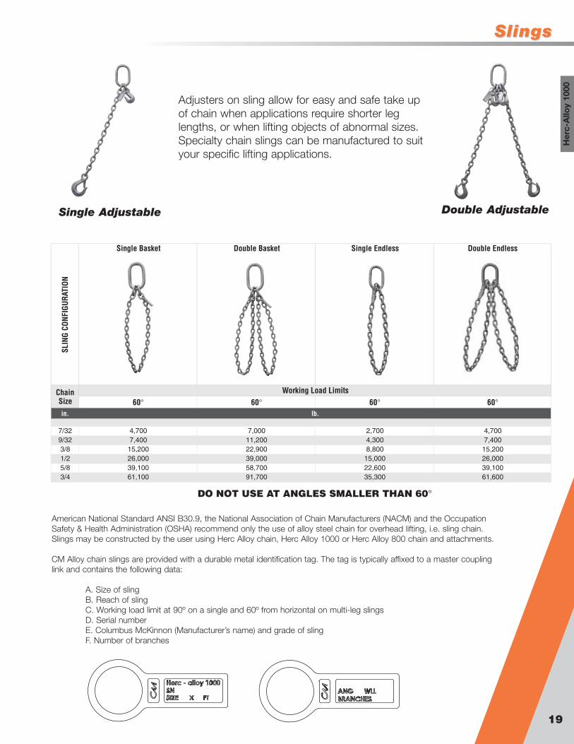
Types of Chain SlingsIn describing the type, the following symbols should be used ifattachments are other than standard, give detail specifications.
First symbol (basic type)S Single chain slingC Single choker chain sling with a standard end link on
each end, no hookD Double branch chain sling (2 legs)T Triple branch chain sling (3 legs)Q Quad branch chain sling (4 legs)
Second symbol (type of master link or end link)O Oblong master link of standard dimensions
Third symbol (type of hook)S Sling hookG Grab hookF Foundry hookL Lodelok hook
Additional coding is defined as followsAS Adjustable singleES Endless singleSAL Single adjustable loopAD Adjustable doubleSB Single basketED Endless doubleDAL Double adjustable loopDB Double basket
90˚60˚ 45˚ 30˚ 60˚ 45˚ 30˚
SLIN
G CO
NFIG
URAT
ION
60° 45° 30° 60° 45° 30° 60° 45° 30°in.
7/32 4,700 3,800 2,700 7,000 5,700 4,000 7,000 5,700 4,0009/32 7,400 6,100 4,300 11,200 9,100 6,400 11,200 9,100 6,4003/8 15,200 12,400 8,800 22,900 18,700 13,200 22,900 18,700 13,2001/2 26,000 21,200 15,000 39,000 31,800 22,500 39,000 31,800 22,5005/8 39,100 32,000 22,600 58,700 47,900 33,900 58,700 47,900 33,9003/4 61,100 49,900 35,300 91,700 74,900 53,000 91,700 74,900 53,000
DO NOT USE AT ANGLES SMALLER THAN 30°
Working Load Limits for Angles Available (shown Below) for each Sling Type
Single (1 Leg) Double (2 Legs) Triple (3 Legs) Quad (4 Legs)
Chain size 90°
2,7004,3008,800
15,00022,60035,300
lb.
Metric
SlingsSlings
19
Her
c-A
lloy
1000
SLIN
G CO
NFIG
URAT
ION
in.
7/329/323/81/25/83/4
Working Load Limits60° 60°
lb.
DO NOT USE AT ANGLES SMALLER THAN 60°
58,70091,700 35,300
60°
4,7007,400
15,20026,000
60°
7,000
22,90039,000
61,10039,10026,00015,200
61,600
4,3008,800
15,00039,10022,600
2,7007,4004,700
Single Basket
11,200
Double Basket Single Endless Double Endless
Chain Size
Adjusters on sling allow for easy and safe take upof chain when applications require shorter leglengths, or when lifting objects of abnormal sizes.Specialty chain slings can be manufactured to suityour specific lifting applications.
Single Adjustable Double Adjustable
American National Standard ANSI B30.9, the National Association of Chain Manufacturers (NACM) and the OccupationSafety & Health Administration (OSHA) recommend only the use of alloy steel chain for overhead lifting, i.e. sling chain.Slings may be constructed by the user using Herc Alloy chain, Herc Alloy 1000 or Herc Alloy 800 chain and attachments.
CM Alloy chain slings are provided with a durable metal identification tag. The tag is typically affixed to a master couplinglink and contains the following data:
A. Size of slingB. Reach of slingC. Working load limit at 90º on a single and 60º from horizontal on multi-leg slingsD. Serial numberE. Columbus McKinnon (Manufacturer’s name) and grade of slingF. Number of branches
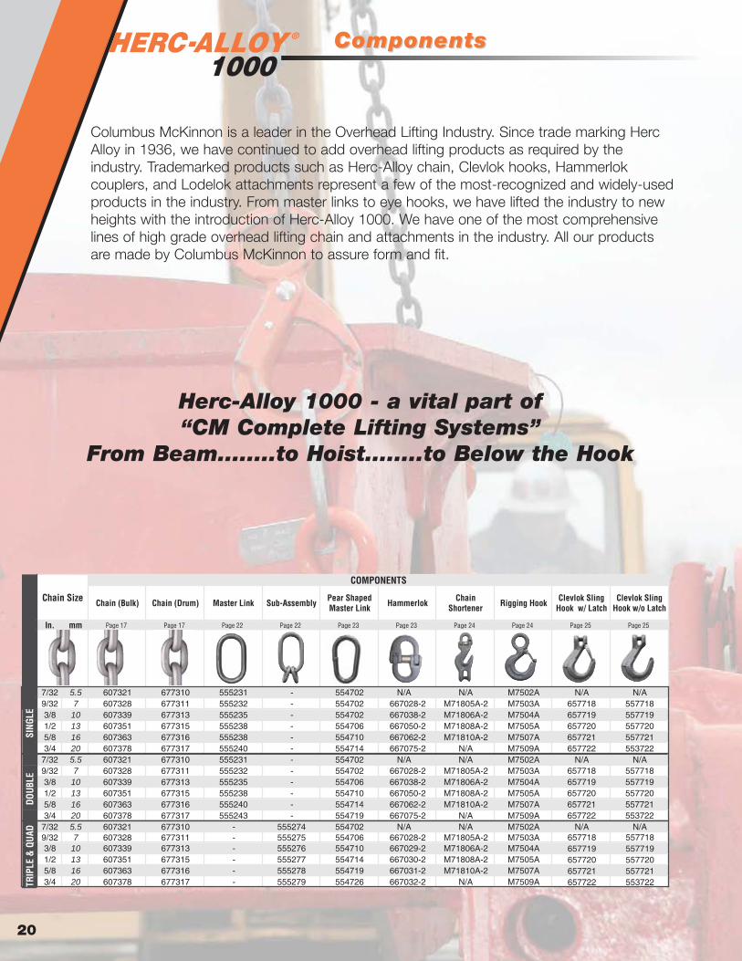
® ComponentsComponents
20
Chain (Bulk) Chain (Drum) Master Link Sub-Assembly Pear Shaped Master Link Hammerlok Chain
Shortener Rigging Hook Clevlok Sling Hook w/ Latch
Clevlok Sling Hook w/o Latch
In. mm Page 17 Page 17 Page 22 Page 22 Page 23 Page 23 Page 24 Page 24 Page 25 Page 25
7/32 5.5 607321 677310 555231 - 554702 N/A N/A M7502A N/A N/A9/32 7 607328 677311 555232 - 554702 667028-2 M71805A-2 M7503A 657718 5577183/8 10 607339 677313 555235 - 554702 667038-2 M71806A-2 M7504A 657719 5577191/2 13 607351 677315 555238 - 554706 667050-2 M71808A-2 M7505A 657720 5577205/8 16 607363 677316 555238 - 554710 667062-2 M71810A-2 M7507A 657721 5577213/4 20 607378 677317 555240 - 554714 667075-2 N/A M7509A 657722 553722
7/32 5.5 607321 677310 555231 - 554702 N/A N/A M7502A N/A N/A9/32 7 607328 677311 555232 - 554702 667028-2 M71805A-2 M7503A3/8 10 607339 677313 555235 - 554706 667038-2 M71806A-2 M7504A1/2 13 607351 677315 555238 - 554710 667050-2 M71808A-2 M7505A5/8 16 607363 677316 555240 - 554714 667062-2 M71810A-2 M7507A3/4 20 607378 677317 555243 - 554719 667075-2 N/A M7509A
7/32 5.5 607321 677310 - 555274 554702 N/A N/A M7502A N/A N/A9/32 7 607328 677311 - 555275 554706 667028-2 M71805A-2 M7503A3/8 10 607339 677313 - 555276 554710 667029-2 M71806A-2 M7504A1/2 13 607351 677315 - 555277 554714 667030-2 M71808A-2 M7505A5/8 16 607363 677316 - 555278 554719 667031-2 M71810A-2 M7507A3/4 20 607378 677317 - 555279 554726 667032-2 N/A M7509A
COMPONENTS
Chain Size
SING
LEDO
UBLE
TRIP
LE &
QUA
D
657718 557718657719 557719657720 557720657721 557721657722 553722
657718 557718657719 557719657720 557720657721 557721657722 553722
Columbus McKinnon is a leader in the Overhead Lifting Industry. Since trade marking HercAlloy in 1936, we have continued to add overhead lifting products as required by theindustry. Trademarked products such as Herc-Alloy chain, Clevlok hooks, Hammerlokcouplers, and Lodelok attachments represent a few of the most-recognized and widely-usedproducts in the industry. From master links to eye hooks, we have lifted the industry to newheights with the introduction of Herc-Alloy 1000. We have one of the most comprehensivelines of high grade overhead lifting chain and attachments in the industry. All our productsare made by Columbus McKinnon to assure form and fit.
Herc-Alloy 1000 - a vital part of “CM Complete Lifting Systems”
From Beam........to Hoist........to Below the Hook

ComponentsComponents
21
Her
c-A
lloy
1000
Eye Sling Hook w/ Latch
Eye Sling Hook w/o
Latch
Clevlok Cradle Grab
Hook
Eye Cradle Grab Hook
Clevlok Foundry Hook
Eye Foundry Hook
Web-Hammerlok Web-Weblok Clevlok Style Eye Style Swivel Style
In. mm Page 25 Page 25 Page 26 Page 26 Page 27 Page 27 Page 28 Page 28 Page 29 Page 29 Page 30
7/32 5.5 N/A N/A N/A N/A N/A N/A N/A N/A N/A N/A N/A9/32 7 558622 458622 659722 559725 475798 474798 867005-1 877005-1 616005 626005 6760053/8 10 558625 458625 659725 559737 475799 474799 867010-1 877010-1 616010 626010 6760101/2 13 558628 458628 659728 559750 475800 474800 867015-1 877015-1 616015 626015 6760155/8 16 558629 458629 659729 559762 475801 474801 867020-1 877020-1 616020 626020 6760203/4 20 558630 458630 N/A 559775 N/A 474802 N/A N/A N/A N/A N/A
7/32 5.5 N/A N/A N/A N/A N/A N/A N/A N/A N/A N/A N/A9/32 7 558622 458622 659722 559725 475798 474798 867005-1 877005-1 616005 626005 6760053/8 10 558625 458625 659725 559737 475799 474799 867010-1 877010-1 616010 626010 6760101/2 13 558628 458628 659728 559750 475800 474800 867015-1 877015-1 616015 626015 6760155/8 16 558629 458629 659729 559762 475801 474801 867020-1 877020-1 616020 626020 6760203/4 20 558630 458630 N/A 559775 N/A 474802 N/A N/A N/A N/A N/A
7/32 5.5 N/A N/A N/A N/A N/A N/A N/A N/A N/A N/A N/A9/32 7 558622 458622 659722 559725 475798 474798 867005-1 877005-1 616005 626005 6760053/8 10 558625 458625 659725 559737 475799 474799 867010-1 877010-1 616010 626010 6760101/2 13 558628 458628 659728 559750 475800 474800 867015-1 877015-1 616015 626015 6760155/8 16 558629 458629 659729 559762 475801 474801 867020-1 877020-1 616020 626020 6760203/4 20 558630 458630 N/A 559775 N/A 474802 N/A N/A N/A N/A N/A
COMPONENTS LODELOK COMPONENTS
Chain Size
SING
LEDO
UBLE
TRIP
LE &
QUA
D

®
Sub-Assembly
Master Link & Sub-AssembliesMaster Link & Sub-Assemblies
Master Link
22
A
B
C
• Designed to accept Herc-Alloy 1000 chain and components
• Durable gray powder coated finish• May be used for mechanical and welded
sling assemblies• 100% proof tested
Material Diameter Inside Length Inside Width
SINGLE DOUBLE TRIPLE QUAD
in. lb. in. in. in. lb.13/32 5,400 555231 0.406 3.000 1.500 0.33 7/32 7/32 -- --
1/2 8,600 555232 0.512 5.000 2.500 0.81 9/32 9/32 7/32 7/323/4 17,600 555235 0.750 5.500 2.750 2.08 3/8 3/8 9/32 9/321 30,000 555238 1.000 7.000 3.500 4.59 1/2 & 5/8 1/2 3/8 3/8
1 1/4 45,200 555240 1.250 8.750 4.375 9.31 3/4 5/8 1/2 1/21 1/2 70,600 555243 1.500 10.500 5.250 15.6 -- 3/4 5/8 5/81 3/4 105,900 555246 1.750 12.000 6.000 24.4 -- -- 3/4 3/4
Weight
Imperial
Type and Size of Chain Sling on Which UsedNominal DimensionsTrade Size
Working Load Limit Product Code
A B C
in. in. in. in.
Material Diameter
Inside Length
Inside Width
Material Diameter
Inside LengthInside
Width TRIPLE QUAD
in. lb. in. in. in. in. in. in. lb.1/2 7,000 555274 0.512 3.000 1.500 0.437 1.063 1.750 1.04 7/32 7/323/4 11,200 555275 0.750 5.500 2.750 0.468 0.875 1.563 2.08 9/32 9/321 22,900 555276 1.000 7.000 3.500 0.781 1.500 2.625 4.59 3/8 3/8
1 1/4 39,000 555277 1.250 8.750 4.375 0.906 1.750 3.125 9.16 1/2 1/21 1/2 58,700 555278 1.500 10.500 5.250 1.125 2.250 4.000 15.66 5/8 5/81 3/4 91,700 555279 1.750 12.000 6.000 1.500 2.750 5.250 24.44 3/4 3/4
M t i
Weight
Intermediate Link Nom. Dims.Master Link Nom. Dims.Trade Size
Working Load Limit at 60º
Product Code
Type and Size of Chain Sling on Which Used
ImperialA B C D E F
in. in.
A
B
C
DE
F
• Designed for Triple and Quad branch Herc-Alloy 1000 chain slings
• Consists of an Oblong Master Link and two welded Master Coupling Links
• Durable gray powder coated finish• May be used for mechanical or welded sling
assemblies• 100% proof tested

Pear Shaped Master Link & HammerlokPear Shaped Master Link & Hammerlok
Hammerlok
Pear Shaped Master Link
23
Her
c-A
lloy
1000
A Max B max C D F
in. lb. in. in. in. in. in. in. lb.9/32 4,300 667028-2 R667028-2 0.365 0.435 2.75 0.71 0.541 1.69 0.283/8 8,800 667038-2 R667038-2 0.502 0.591 3.00 1.16 0.910 2.50 0.841/2 15,000 667050-2 R667050-2 0.678 0.780 3.80 1.43 1.097 3.19 1.875/8 22,600 667062-2 R667062-2 0.804 0.905 4.54 1.74 1.317 3.88 3.133/4 35,300 667075-2 R667075-2 0.973 1.071 5.36 2.09 1.516 4.69 5.75
Imperial
WeightDimensions
Size Working Load Limit Product Code Load Pin Kit
Product Code E
F
A E
B
C
D
• New Classic stainless steel non-corrosive retainer• New pin and retainer design adds protection against
twist and side load problems• Large retainer diameter adds shock load protection
• Made from alloy material• Proof tested at two times WLL• Durable gray powder coated finish• Custom sizes available upon request B
C
A
D
A B C D
in. lb. in. in. in. in. lb. in. in. in.1/2 HA51 9,000 554702 0.512 5.313 2.500 1.250 0.81 7/32,9/32 & 3/8 7/32 & 9/32 7/32
3/4 HA79 18,000 554706 0.750 5.625 2.750 2.000 2.08 1/2 3/8 9/32
1 HA103 30,300 554710 1.000 7.250 3.500 2.625 4.59 5/8 1/2 3/8
1-1/4 HA129 45,500 554714 1.250 8.750 4.625 3.250 9.17 3/4 5/8 1/2
1-1/2 HA153 71,200 554719 1.500 10.500 5.250 3.875 15.28 1 3/4 5/8
1-3/4 HA179 86,000 554723 1.750 12.000 6.000 4.500 23.93 – –
2 HA201 120,000 554726 2.000 14.000 7.000 3.500 35.93 3/4
2-1/4 HA229 182,000 554731 2.250 16.000 8.000 6.000 52.83 –
Finished Code
Diameter Inside Length
Inside Width
Imperial
Type and Size of Chain SlingWeight
Single Double TripleTrade Size
Catalog No.
Working Load Limit
Inside Width
––
–
–
–

®
Rigging Hook
Chain ShorChain Shortener & Rigging Hooktener & Rigging Hook
Chain Shortener
24
A B C D F G H J K L O P R T
in. lb. in. in. in. in. in. in. in. in. in. in. in. in. in. in. lb.7/32 2,700 M7502A M7402A 1.50 0.75 0.38 3.06 1.25 0.87 1.05 0.93 0.63 4.37 0.93 2.12 3.13 0.87 0.669/32 4,300 M7503A M7403A 1.75 0.88 0.44 3.33 1.38 0.94 1.11 0.97 0.71 5.04 0.97 2.27 3.66 0.97 1.125/16 5,700 M7504A M7404A 2.13 1.13 0.50 3.67 1.50 1.06 1.21 1.06 0.88 5.63 1.06 2.54 4.09 1.03 1.463/8 8,800 M7505A M7405A 2.50 1.25 0.63 4.20 1.63 1.27 1.43 1.19 0.94 6.55 1.16 2.80 4.67 1.16 2.421/2 15,000 M7507A M7407A 3.06 1.56 0.75 5.11 2.00 1.44 1.63 1.50 1.31 7.97 1.41 3.47 5.78 1.53 4.105/8 22,600 M7509A M7409A 3.88 2.00 0.94 6.24 2.50 1.82 2.01 1.78 1.68 10.07 1.69 4.59 7.31 1.94 8.16
Dimensions
Imperial
Size Working Load Limit Weight
Product Code
w/o latch
Product Code
w/ latch
CA
B
L R
K
G
H K
D
T
F
O
J
P
• Large eye to easily accommodate other G100 fittings
• Quench & tempered alloy steel• Painted grey for easy identification
C D G H J K L F M S T
in. lb. in. in. in. in. in. in. in. in. in. in. in. lb.9/32 4,300 M71805A-2 0.71 2.19 5.86 0.38 0.80 1.00 0.36 0.38 3.38 0.21 0.50 1.203/8 8,800 M71806A-2 1.16 2.74 7.61 0.47 1.16 1.40 0.51 0.47 4.74 0.31 0.71 2.501/2 15,000 M71808A-2 1.43 3.34 9.36 0.65 1.37 2.08 0.63 0.65 5.82 0.41 0.86 4.805/8 22,600 M71810A-2 1.74 4.19 11.56 0.79 1.53 2.47 0.75 0.79 7.04 0.48 1.06 8.20
Imperial
DimensionsProduct CodeSize Working
Load Limit Weight
D
F
GM
K
(PIN DIA)
(PIN DIA)
HL
S
J
T
C• Quickly and easily adjust chain length of sling when
the load has uneven pick points• Painted gray for easy Grade 100 identification• Marked with both fraction and metric sizes• Forged alloy steel - quenched & tempered• Mechanically attaches directly to master ring
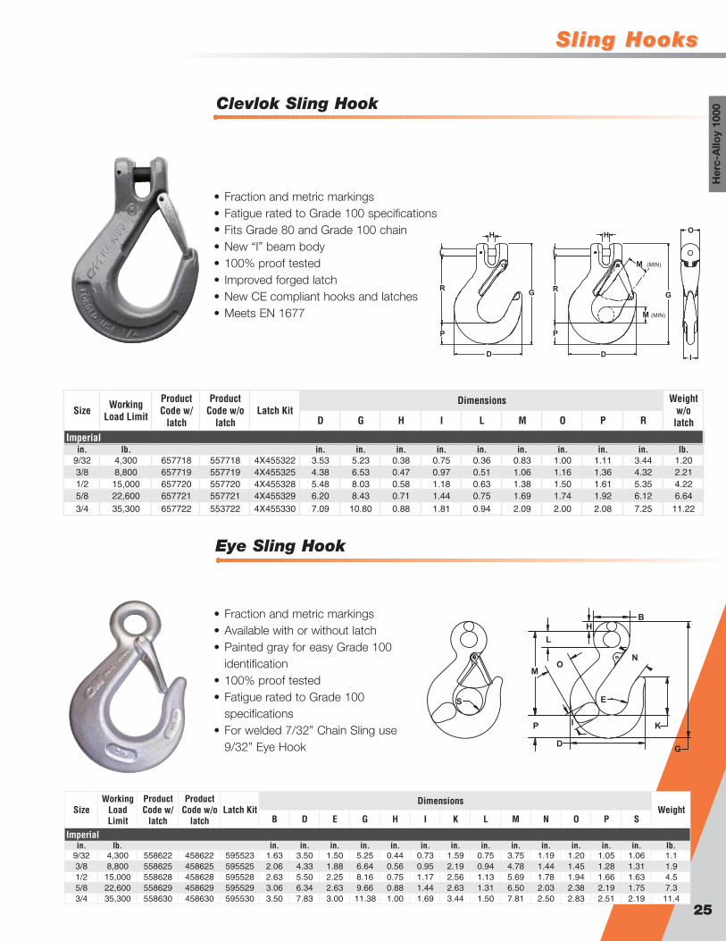
Sling HooksSling Hooks
Eye Sling Hook
Clevlok Sling Hook
25
Her
c-A
lloy
1000
M (MIN)
M (MIN)
I
O
D
P
R
L
H
G
P
H
G
D
R
L
D G H I L M O P R
in. lb. in. in. in. in. in. in. in. in. in. lb.9/32 4,300 657718 557718 4X455322 3.53 5.23 0.38 0.75 0.36 0.83 1.00 1.11 3.44 1.203/8 8,800 657719 557719 4X455325 4.38 6.53 0.47 0.97 0.51 1.06 1.16 1.36 4.32 2.211/2 15,000 657720 557720 4X455328 5.48 8.03 0.58 1.18 0.63 1.38 1.50 1.61 5.35 4.225/8 22,600 657721 557721 4X455329 6.20 8.43 0.71 1.44 0.75 1.69 1.74 1.92 6.12 6.643/4 35,300 657722 553722 4X455330 7.09 10.80 0.88 1.81 0.94 2.09 2.00 2.08 7.25 11.22
Imperial
Size Working Load Limit
Weight w/o
latch
Product Code w/o
latch
Product Code w/
latchLatch Kit
Dimensions
• Fraction and metric markings• Fatigue rated to Grade 100 specifications• Fits Grade 80 and Grade 100 chain• New “I” beam body• 100% proof tested• Improved forged latch• New CE compliant hooks and latches• Meets EN 1677
B D E G H I K L M N O P S
in. lb. in. in. in. in. in. in. in. in. in. in. in. in. in. lb.9/32 4,300 558622 458622 595523 1.63 3.50 1.50 5.25 0.44 0.73 1.59 0.75 3.75 1.19 1.20 1.05 1.06 1.13/8 8,800 558625 458625 595525 2.06 4.33 1.88 6.64 0.56 0.95 2.19 0.94 4.78 1.44 1.45 1.28 1.31 1.91/2 15,000 558628 458628 595528 2.63 5.50 2.25 8.16 0.75 1.17 2.56 1.13 5.69 1.78 1.94 1.66 1.63 4.55/8 22,600 558629 458629 595529 3.06 6.34 2.63 9.66 0.88 1.44 2.63 1.31 6.50 2.03 2.38 2.19 1.75 7.33/4 35,300 558630 458630 595530 3.50 7.83 3.00 11.38 1.00 1.69 3.44 1.50 7.81 2.50 2.83 2.51 2.19 11.4
Imperial
SizeWorking
Load Limit
WeightDimensionsProduct
Code w/o latch
Product Code w/
latchLatch Kit
B
N
G
K
D
E
P
M
I
O
L
H
S
• Fraction and metric markings• Available with or without latch• Painted gray for easy Grade 100
identification• 100% proof tested• Fatigue rated to Grade 100
specifications• For welded 7/32” Chain Sling use
9/32” Eye Hook

®
Eye Cradle Grab Hook
Grab HooksGrab Hooks
Clevlok Cradle Grab Hook
26
D G H J K L M P R
in. lb. in. in. in. in. in. in. in. in. in. lb.9/32 4,300 659722 2.18 3.38 0.38 0.80 0.95 0.36 0.38 0.82 1.86 0.633/8 8,800 659725 2.72 4.33 0.47 1.16 1.27 0.51 0.47 1.02 2.47 1.301/2 15,000 659728 3.32 5.27 0.65 1.24 1.54 0.63 0.65 1.18 3.05 2.105/8 22,600 659729 4.18 6.54 0.79 1.53 1.92 0.75 0.79 1.41 3.75 4.20
Imperial
Product CodeSize Working
Load Limit WeightDimensions
H
M
G
R
L
P
D
J
K
• Fits grade 80 and grade 100 chain• Fraction and metric markings• New “I” beam body with chain cradle saddle• 100% proof tested• Fatigue rated to grade 100 specifications
B D E G H I K L M P
in. lb. in. in. in. in. in. in. in. in. in. lb.9/32 4,300 559725 1.38 1.91 0.36 3.70 0.38 1.06 1.04 0.63 2.57 0.76 0.553/8 8,800 559737 1.78 2.78 0.47 4.81 0.50 1.38 1.49 0.78 3.28 1.04 1.391/2 15,000 559750 2.28 3.63 0.59 6.19 0.63 1.81 1.98 1.03 4.22 1.51 3.055/8 22,600 559762 2.75 4.41 0.75 7.62 0.75 2.13 2.39 1.25 5.06 1.80 4.363/4 35,300 559775 3.19 5.23 0.88 8.99 0.88 2.88 3.50 1.44 6.25 1.88 9.00
Imperial
Size Working Load Limit WeightProduct Code
Dimensions
in.
B
H
KE
P
D
M
L
• Fraction and metric markings• Painted gray for easy grade 100 identification• 100% proof tested• Fatigue rated to grade 100 specifications• Certification of test available• For welded 7/32” Chain Sling use 9/32”
Eye Cradle Hook

FoundrFoundry Hooksy Hooks
Eye Foundry Hook
Clevlok Foundry Hook
27
Her
c-A
lloy
1000
D G H J K L M P R
in. lb. lb.9/32 4,300 475798 4.82 6.52 0.35 1.00 1.00 0.357 2.55 1.24 4.59 2.433/8 8,800 475799 5.73 7.87 0.47 1.16 1.27 0.507 3.05 1.43 5.59 4.141/2 15,000 475800 6.83 9.40 0.59 1.50 1.50 0.625 3.55 1.75 6.58 7.105/8 22,600 475801 7.94 10.98 0.71 1.74 1.81 0.750 4.07 2.03 7.69 12.03
Imperial
Product CodeSize Working
Load Limit WeightDimensions
in. in. in. in. in. in. in. in. in.
M
J
K
(PIN DIA)L
D
H
RG
P
• Clevlok head designed for easy assembly• “I” beam body design increases grip when
moving from load• Quench & tempered alloy steel• Individually proof tested
B D E G H I K L M N O R
in. lb. in. in. in. in. in. in. in. in. in. in. in. in. lb.9/32 4,300 474798 1.56 4.75 2.50 6.45 0.47 1.00 1.56 0.63 4.75 2.50 1.23 0.25 2.43/8 8,800 474799 2.00 5.75 3.00 7.88 0.63 1.27 1.88 0.75 5.75 3.00 1.50 0.31 4.51/2 15,000 474800 2.50 6.75 3.50 9.38 0.75 1.50 2.22 1.00 6.88 3.50 1.75 0.38 7.15/8 22,600 474801 3.00 7.81 4.00 10.97 0.88 1.81 2.63 1.13 8.06 4.00 2.03 0.44 11.63/4 35,300 474802 3.50 9.13 4.50 12.81 1.00 2.20 3.00 1.50 9.25 4.50 2.56 0.50 20.0
SizeWorking
Load Limit
Product Code Weight
Dimensions
Imperial
H B
L
N R (SPHER.)
K
E
D (REF)
O
G (REF)
M
I
• Throat opening to 4.5” (114 mm)• Painted gray for easy grade 100
identification• 100% proof tested• Fatigue rated to grade 100 specifications• Certification of test available• For welded 7/32” Chain Sling use 9/32”
Eye Foundry Hook
®
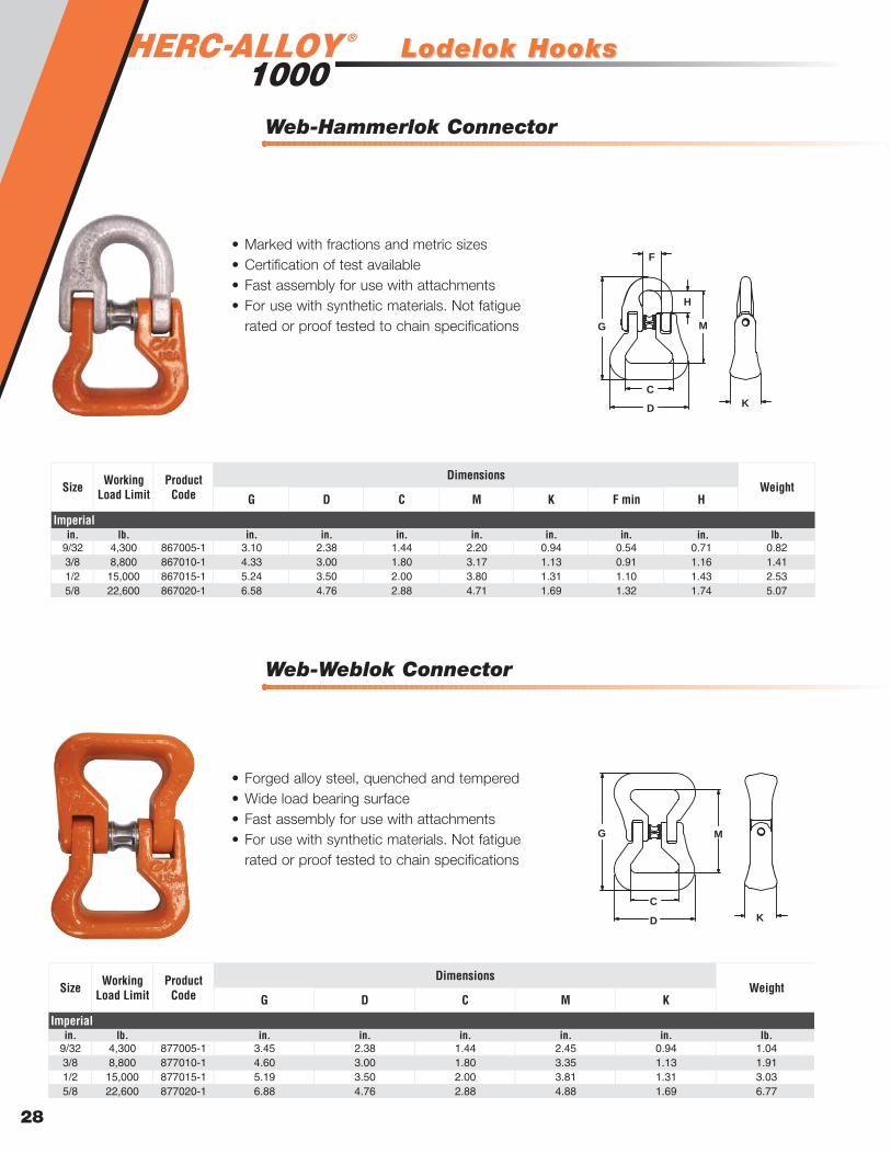
Web-Weblok Connector
Lodelok HooksLodelok Hooks
Web-Hammerlok Connector
28
G D C M K F min H
in. lb. in. in. in. in. in. in. lb.9/32 4,300 867005-1 3.10 2.38 1.44 2.20 0.94 0.54 0.71 0.823/8 8,800 867010-1 4.33 3.00 1.80 3.17 1.13 0.91 1.16 1.411/2 15,000 867015-1 5.24 3.50 2.00 3.80 1.31 1.10 1.43 2.535/8 22,600 867020-1 6.58 4.76 2.88 4.71 1.69 1.32 1.74 5.07
Imperial
DimensionsProduct CodeSize Working
Load Limit Weight
in.
C
DK
M
H
F
G
• Marked with fractions and metric sizes• Certification of test available• Fast assembly for use with attachments• For use with synthetic materials. Not fatigue
rated or proof tested to chain specifications
G D C M K
in. lb. in. in. in. in. in. lb.9/32 4,300 877005-1 3.45 2.38 1.44 2.45 0.94 1.043/8 8,800 877010-1 4.60 3.00 1.80 3.35 1.13 1.911/2 15,000 877015-1 5.19 3.50 2.00 3.81 1.31 3.035/8 22,600 877020-1 6.88 4.76 2.88 4.88 1.69 6.77
Dimensions
Imperial
Product CodeSize Working
Load Limit Weight
D
C
K
MG
• Forged alloy steel, quenched and tempered• Wide load bearing surface• Fast assembly for use with attachments• For use with synthetic materials. Not fatigue
rated or proof tested to chain specifications
Lodelok HooksLodelok Hooks
Eye Style
Clevlok Style
29
Her
c-A
lloy
1000
A B C D E Fmin G H J
in. lb. in. in. in. in. in. in. in. in. in. lb.9/32 4,300 626005 656005 2.00 1.31 5.43 1.00 3.89 1.563 1.47 0.63 1.19 2.643/8 8,800 626010 656010 2.50 1.78 7.41 1.25 5.03 2.250 2.00 0.75 1.25 4.861/2 15,000 626015 656015 3.44 2.38 9.38 1.75 6.68 2.813 2.59 1.00 1.63 10.465/8 22,600 626020 656020 3.94 2.62 10.71 2.00 8.04 3.125 2.92 1.25 1.88 16.52
Imperial
Replace Latch Kit
Part #Size Working
Load Limit Weight DimensionsProduct
Code
A
G
E
D
F
B
C
• Large eye design for use with chain, wire rope and synthetic material
• Factory replaceable pins• 100% proof tested• Fatigue rated to grade 100 specifications• For welded 7/32” Chain Sling use 9/32”
Eye Lodelok Hook
D G H J K L M P R
in. lb. in. in. in. in. in. in. in. in. in. lb.9/32 4,300 616005 656005 3.89 6.37 0.35 1.00 1.19 0.36 1.56 1.00 4.68 2.623/8 8,800 616010 656010 5.03 8.20 0.47 1.16 1.25 0.51 2.25 1.25 6.11 4.931/2 15,000 616015 656015 6.68 10.07 0.59 1.50 1.63 0.63 2.81 1.75 7.25 9.325/8 22,600 616020 656020 8.04 11.62 0.71 1.74 1.88 0.75 3.19 2.00 8.36 14.70
Imperial
Replace Latch Kit
Part #Size Working
Load Limit WeightDimensionsProduct
Code
H J
K
M
GR
L
P
D
• High cycling, long life spring• Factory replaceable pins• “I” beam construction for greater strength• 100% proof tested• Fatigue rated to grade 100 specifications
®
Lodelok® Hook Reference Chart
Lodelok HooksLodelok Hooks
Swivel Style
30
A B M P D F min K H
in. lb. in. in. in. in. in. in. in. in. lb.9/32 4,300 676005 696005 656005 1.50 1.31 7.05 1.00 3.89 1.56 1.19 0.62 3.73/8 8,800 676010 696010 656010 1.78 1.62 9.14 1.25 5.03 2.25 1.25 0.77 5.11/2 15,000 676015 696015 656015 2.25 1.82 10.85 1.75 6.68 2.81 1.63 0.93 11.25/8 22,600 676020 696020 656020 2.75 2.38 12.80 2.00 8.04 3.13 1.88 1.00 18.1
Imperial
Bushing Style Product CodeSize Working
Load Limit WeightDimensionsReplace
Latch Kit Part #
Bearing Style Product Code
D
B
M
P
F
A
K
H• The eye easily positions to attach to the load
• Factory replaceable pins• 100% proof tested• Fatigue rated to grade 100
specifications• Certification of test available• For welded 7/32” Chain Sling use
9/32” Swivel Lodelok Hook
• Do not apply load unless latch and hook are completelyclosed and locked
• Make certain that the latch does not support any part of theload
• When lifting, make certain that the load is firmly seated in thebase (bowl) of the hook
• Inspect hook and latch periodically. If the hook or latch isdamaged or if the latch fails to interlock with the tip, thehook should be removed from service
• Do not exceed the working load limit• Do not use if the hook is visibly distorted, damaged or worn• Keep body and other objects clear of the latch when closing
to avoid the pinch point• Do not side load or tip load hook• User should be properly trained and understand safe rigging
practices
WLL (Working Load Limit) is the maximum load a product isdesigned to support during use
Attachment Type Size WLL 4:1 WLL 5:1
in. lb. lb.
Grade 80 9/32 3,500 2,800
Grade 100 9/32 4,300 3,440
Round Sling (Vertical) #1 Purple 3,250 2,600
Wire Rope (EIP) max. 3/8 3,775 3,020
Grade 80 3/8 7,100 5,680
Grade 100 3/8 8,800 7,040
Round Sling (Vertical) #2 Green 6,625 5,300
Wire Rope (EIP) max. 9/16 8,400 6,720
Grade 80 1/2 12,000 9,600
Grade 100 1/2 15,000 12,000
Round Sling (Vertical) #3 Yellow 10,500 8,400
Round Sling (Vertical) #4 Tan 13,250 10,600
Wire Rope (EIP) max. 3/4 14,700 11,760
Grade 80 5/8 18,000 14,400
Grade 100 5/8 22,600 18,080
Round Sling (Vertical) #5 Red 16,500 13,200
Round Sling (Vertical) #6 White 21,000 16,800
Wire Rope (EIP) max. 7/8 19,900 15,920
Grade 80 3/4 28,300 22,640
Grade 100 3/4 35,300 28,240
Round Sling (Vertical) #7 Blue 26,500 21,200
Round Sling (Vertical) #8 Orange 31,250 25,000
Wire Rope (EIP) max. 1-1/8 32,500 26,000
Hook Size: 9/32" • Maximum WLL: 4,300 lbs.
Hook Size: 3/8" • Maximum WLL: 8,800 lbs.
Hook Size: 1/2" • Maximum WLL: 15,000 lbs.
Hook Size: 5/8" • Maximum WLL: 22,600 lbs.
Hook Size: 3/4" • Maximum WLL: 35,300 lbs.
Bushing Style Bearing Style
Ove
rhead L
ifti
ng
Ove
rhead L
ifti
ng
Care, Use & Inspection . . . . . . . . . . . . . . . . . . . . . . . 32Herc-Alloy 800 Chain . . . . . . . . . . . . . . . . . . . . . . . . .33Herc-Alloy 800 Slings . . . . . . . . . . . . . . . . . . . . . .34-35Herc-Alloy 800 Components . . . . . . . . . . . . . . . .36-37Master Link . . . . . . . . . . . . . . . . . . . . . . . . . . . . . . . .38Forged Master Link . . . . . . . . . . . . . . . . . . . . . . . . . .38Master Link with Flats . . . . . . . . . . . . . . . . . . . . . . . .39Flat Bottom Master Link . . . . . . . . . . . . . . . . . . . . . .39Sub-Assembly . . . . . . . . . . . . . . . . . . . . . . . . . . . . . .40Sub-Assembly with Flats . . . . . . . . . . . . . . . . . . . . .40Master Ring . . . . . . . . . . . . . . . . . . . . . . . . . . . . . . . .41Grab Link . . . . . . . . . . . . . . . . . . . . . . . . . . . . . . . . . .41Omegalok Connector . . . . . . . . . . . . . . . . . . . . . . . . .42Hammerlok . . . . . . . . . . . . . . . . . . . . . . . . . . . . . . . . .42Clevlok Sling Hook . . . . . . . . . . . . . . . . . . . . . . . . . . .43Eye Sling Hook . . . . . . . . . . . . . . . . . . . . . . . . . . . . . .43Clevlok Grab Hook . . . . . . . . . . . . . . . . . . . . . . . . . . .44Clevlok Cradle Grab Hook . . . . . . . . . . . . . . . . . . . . .44Eye Cradle Grab Hook . . . . . . . . . . . . . . . . . . . . . . . .45Eye Foundry Hook . . . . . . . . . . . . . . . . . . . . . . . . . . .45Sorting Hook . . . . . . . . . . . . . . . . . . . . . . . . . . . . . . .46Sorting Hook with Handle . . . . . . . . . . . . . . . . . . . . .46Plate Hook . . . . . . . . . . . . . . . . . . . . . . . . . . . . . . . . .47“S” Hook . . . . . . . . . . . . . . . . . . . . . . . . . . . . . . . . . .47Specialty Hooks . . . . . . . . . . . . . . . . . . . . . . . . . . . . .48Stainless Steel Chain . . . . . . . . . . . . . . . . . . . . . . . . .49Stainless Steel Master Link . . . . . . . . . . . . . . . . . . . .50
® CarCare, Use & Inspectione, Use & Inspection
32
The life and strength of Herc-Alloy 800 chain slings depend on proper inspection, maintenance and use. For additional information, refer to ASME B30.9 and OSHA 1910.184.
CareChain requires careful storage and regular maintenance. • Store chains on an A frame in a clean, dry place.• To avoid corrosion, oil chains before prolonged storage.• Do not heat Herc-Alloy 800 chain; this will alter its
thermal treatment.
UseTo protect both operators and materials, observe theseprecautions when using chain slings:
• Before use, inspect chain and attachments following the instructions under “Inspection” below.
• Do not exceed working load limit. Any of the factors listed here can reduce the load the chain will hold:
- Acceleration in rate of load application can produce dangerous overloads.
- Variations in the angle of the load to the sling, will change the WLL please refer to the chart on page 36 for proper WLL.
- Twisting, knotting or kinking, subjects links to unusual loading, decreasing the working load of the sling.
- Use for purposes other than those for which slings are intended, can reduce the working load of the sling.
• Free chain of all twists, knots and kinks.• Center load in hook(s); hook latch must not support load.• Avoid sudden jerks when lifting or lowering load.• Balance all loads; avoid tipping of loads.• Use pads around sharp corners.• Do not drop load on chains.• Match the size and working load limits of attachments such
as hooks and rings to the size and working load limits of the chain.
• For overhead lifting, use only alloy chain and attachments.
InspectionIt is important both to inspect chain slings regularly and to keep arecord of all chain inspections. Follow this guide for such aninspection system.
• Before inspecting, clean chain with a non-acid/non-caustic solvent so that marks, nicks, wear and other defects are visible.
• Inspect each link for these conditions:- Twists and bends.- Nicks or gouges.- Excessive wear at bearing points.
• Stretch.• Distorted or damaged master links, coupling links or
attachments, especially spread in throat opening of hooks.• Mark plainly with paint each link or attachment showing
any of the conditions listed here to indicate rejection; remove from service until properly repaired.
Wear Allowances of Herc-Alloy 800 ChainMeasure cross section at link ends to determine wear. If chainis worn to less than the minimum allowable thickness, removefrom service.
CM Chain Inspection ProgramsCM provides chain users with a wide range of informativematerials and instructive programs on chain and chaininspection. Our colorful chain safety poster/chart and our fact-filled booklet, “CM Lifting, Pulling & Binding Products ManualPMC-10,” are available on request.
Use of Chain & Components UnderExtreme Temperature ConditionsWhen the chain itself is subjected to temperatures shownhere, working load limits should be reduced as indicated.
The identification tag found on each chain sling contains thisinformation:
• Grade • Size • Reach • Serial Number • Number of Legs• Working Load Limit (at a specific angle of lift)
T
in. mm in. mm7/32 5.5 0.189 4.89/32 7.0 0.239 6.13/8 10.0 0.342 8.71/2 13.0 0.443 11.35/8 16.0 0.546 13.9
3/4 20.0 0.687 17.5
Minimum Allowable Thickness (T)Chain Size
While at Temperature
After Exposure to Temperature
F CBelow 400 Below 204 None None
400 204 10% None500 260 15% None600 316 20% 5%700 371 30% 10%
800 427 40% 15%
900 482 50% 20%
1000 538 60% 25%
Reduction of Working Load Limit
Temperature
HerHerc-Alloy 800 Chainc-Alloy 800 Chain
33
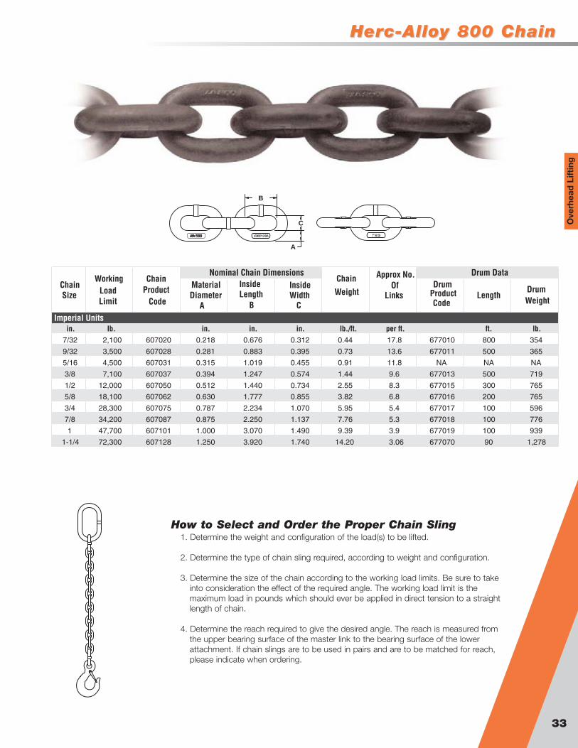
Ove
rhea
d L
iftin
g
Material Diameter
A
InsideLength
B
InsideWidth
C
Drum
CodeLength
Drum
in. lb. in. in. in. lb./ft. per ft. ft. lb.7/32 2,100 607020 0.218 0.676 0.312 0.44 17.8 677010 800 354
9/32 3,500 607028 0.281 0.883 0.395 0.73 13.6 677011 500 365
5/16 4,500 607031 0.315 1.019 0.455 0.91 11.8 NA NA NA
3/8 7,100 607037 0.394 1.247 0.574 1.44 9.6 677013 500 719
1/2 12,000 607050 0.512 1.440 0.734 2.55 8.3 677015 300 765
5/8 18,100 607062 0.630 1.777 0.855 3.82 6.8 677016 200 765
3/4 28,300 607075 0.787 2.234 1.070 5.95 5.4 677017 100 596
7/8 34,200 607087 0.875 2.250 1.137 7.76 5.3 677018 100 776
1 47,700 607101 1.000 3.070 1.490 9.39 3.9 677019 100 939
1-1/4 72,300 607128 1.250 3.920 1.740 14.20 3.06 677070 90 1,278
Imperial Units
Chain Size Load
Limit
Chain
Code
Nominal Chain DimensionsChain
Weight
Approx No. Of
Links
Drum DataWorking
Product ProductWeight
A
B
C
How to Select and Order the Proper Chain Sling1. Determine the weight and configuration of the load(s) to be lifted.
2. Determine the type of chain sling required, according to weight and configuration.
3. Determine the size of the chain according to the working load limits. Be sure to takeinto consideration the effect of the required angle. The working load limit is themaximum load in pounds which should ever be applied in direct tension to a straightlength of chain.
4. Determine the reach required to give the desired angle. The reach is measured fromthe upper bearing surface of the master link to the bearing surface of the lowerattachment. If chain slings are to be used in pairs and are to be matched for reach,please indicate when ordering.

® SlingsSlings
34
Types of Chain SlingsIn describing the type, the following symbols should be used ifattachments are other than standard, give detail specifications.
First symbol (basic type)S Single chain slingC Single choker chain sling with a standard end link on
each end, no hookD Double branch chain sling (2 legs)T Triple branch chain sling (3 legs)Q Quad branch chain sling (4 legs)
Second symbol (type of master link or end link)O Oblong master link of standard dimensions
Third symbol (type of hook)S Sling hookG Grab hookF Foundry hookL Lodelok hook
Additional coding is defined as followsAS Adjustable singleES Endless singleSAL Single adjustable loopAD Adjustable doubleSB Single basketED Endless doubleDAL Double adjustable loopDB Double basket
Single (1 Leg)
90° 60° 45° 30° 60° 45° 30° 60° 45° 30°
7/32 2,100 3,600 3,000 2,100 5,500 4,400 3,200 5,500 4,400 3,200
9/32 3,500 6,100 4,900 3,500 9,100 7,400 5,200 9,100 7,400 5,200
5/16 4,500 7,800 6,400 4,500 11,700 9,500 6,800 11,700 9,500 6,800
3/8 7,100 12,300 10,000 7,100 18,400 15,100 10,600 18,400 15,100 10,600
1/2 12,000 20,800 17,000 12,000 31,200 25,500 18,000 31,200 25,500 18,000
5/8 18,100 31,300 25,600 18,100 47,000 38,400 27,100 47,000 38,400 27,100
3/4 28,300 49,000 40,000 28,300 73,500 60,000 42,400 73,500 60,000 42,400
7/8 34,200 59,200 48,400 34,200 88,900 72,500 51,300 88,900 72,500 51,300
1 47,700 82,600 67,400 47,700 123,900 101,200 71,500 123,900 101,200 71,500
1-1/4 72,300 125,200 102,200 72,300 187,800 153,400 108,400 187,800 153,400 108,400
Double (2 Legs) Triple (3 Legs) Quad (4 Legs)
lb.Imperial
Working Load Limit for Angles Available (shown below) Chain Size
in.
90˚60˚ 45˚ 30˚ 60˚ 45˚ 30˚
SlingsSlings
35
Ove
rhea
d L
iftin
g
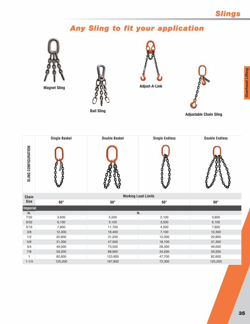
Single Basket Double Basket Single Endless Double Endless
SLIN
G CO
NFIG
URAT
ION
60° 60° 60° 60°
in.7/32 3,600 5,500 2,100 3,600
9/32 6,100 9,100 3,500 6,100
5/16 7,800 11,700 4,500 7,800
3/8 12,300 18,400 7,100 12,300
1/2 20,800 31,200 12,000 20,800
5/8 31,300 47,000 18,100 31,300
3/4 49,000 73,500 28,300 49,000
7/8 59,200 88,900 34,200 59,200
1 82,600 123,900 47,700 82,600
1-1/4 125,200 187,800 72,300 125,200
Chain Size
Working Load Limits
Imperiallb.
Any Sling to fit your applicationAny Sling to fit your application
Magnet Sling
Bail Sling
Adjust-A-Link
Adjustable Chain Sling
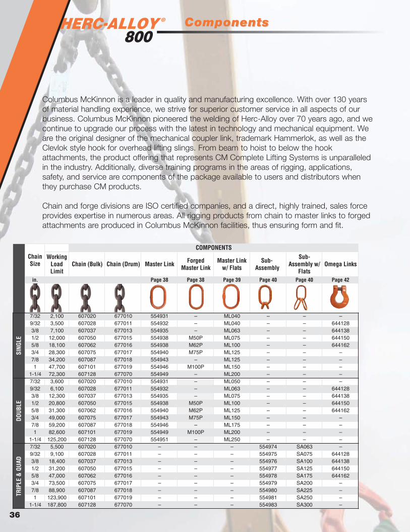
® ComponentsComponents
36
in. Page 38 Page 38 Page 39 Page 40 Page 40 Page 42
7/32 2,100 607020 677010 554931 – ML040 – – –9/32 3,500 607028 677011 554932 – ML040 – – 6441283/8 7,100 607037 677013 554935 – ML063 – – 6441381/2 12,000 607050 677015 554938 M50P ML075 – – 6441505/8 18,100 607062 677016 554938 M62P ML100 – – 6441623/4 28,300 607075 677017 554940 M75P ML125 – – –7/8 34,200 607087 677018 554943 – ML125 – – –1 47,700 607101 677019 554946 M100P ML150 – – –
1-1/4 72,300 607128 677070 554949 – ML200 – – –7/32 3,600 607020 677010 554931 – ML050 – – –9/32 6,100 607028 677011 554932 – ML063 – – 6441283/8 12,300 607037 677013 554935 – ML075 – – 6441381/2 20,800 607050 677015 554938 M50P ML100 – – 6441505/8 31,300 607062 677016 554940 M62P ML125 – – 6441623/4 49,000 607075 677017 554943 M75P ML150 – – –7/8 59,200 607087 677018 554946 – ML175 – – –1 82,600 607101 677019 554949 M100P ML200 – – –
1-1/4 125,200 607128 677070 554951 – ML250 – – –7/32 5,500 607020 677010 – – – 554974 SA063 –9/32 9,100 607028 677011 – – – 554975 SA075 6441283/8 18,400 607037 677013 – – – 554976 SA100 6441381/2 31,200 607050 677015 – – – 554977 SA125 6441505/8 47,000 607062 677016 – – – 554978 SA175 6441623/4 73,500 607075 677017 – – – 554979 SA200 –7/8 88,900 607087 677018 – – – 554980 SA225 –1 123,900 607101 677019 – – – 554981 SA250 –
1-1/4 187,800 607128 677070 – – – 554983 SA300 –
COMPONENTS
Master Link w/ Flats
Forged Master Link Omega Links
Sub-Assembly w/
Flats
Sub-Assembly
TRIP
LE &
QUA
D
Master LinkChain (Bulk) Chain (Drum)
SING
LE
Chain Size
Working Load Limit
DOUB
LE
Columbus McKinnon is a leader in quality and manufacturing excellence. With over 130 yearsof material handling experience, we strive for superior customer service in all aspects of ourbusiness. Columbus McKinnon pioneered the welding of Herc-Alloy over 70 years ago, and wecontinue to upgrade our process with the latest in technology and mechanical equipment. Weare the original designer of the mechanical coupler link, trademark Hammerlok, as well as theClevlok style hook for overhead lifting slings. From beam to hoist to below the hookattachments, the product offering that represents CM Complete Lifting Systems is unparalleledin the industry. Additionally, diverse training programs in the areas of rigging, applications,safety, and service are components of the package available to users and distributors whenthey purchase CM products.
Chain and forge divisions are ISO certified companies, and a direct, highly trained, sales forceprovides expertise in numerous areas. All rigging products from chain to master links to forgedattachments are produced in Columbus McKinnon facilities, thus ensuring form and fit.
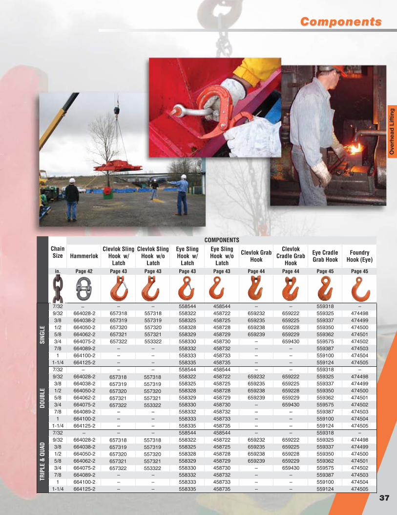
ComponentsComponents
37
Ove
rhea
d L
iftin
g
in. Page 42 Page 43 Page 43 Page 43 Page 43 Page 44 Page 44 Page 45 Page 45
7/32 – – 558544 458544 – – 559318 –9/32 664028-2 657318 557318 558322 458722 659232 659222 559325 4744983/8 664038-2 657319 557319 558325 458725 659235 659225 559337 4744991/2 664050-2 657320 557320 558328 458728 659238 659228 559350 4745005/8 664062-2 657321 557321 558329 458729 659239 659229 559362 4745013/4 664075-2 657322 553322 558330 458730 – 659430 559575 4745027/8 664089-2 – – 558332 458732 – – 559387 4745031 664100-2 – – 558333 458733 – – 559100 474504
1-1/4 664125-2 – – 558335 458735 – – 559124 4745057/32 – – 558544 458544 – – 559318 –9/32 664028-2 558322 458722 659232 659222 559325 4744983/8 664038-2 558325 458725 659235 659225 559337 4744991/2 664050-2 558328 458728 659238 659228 559350 4745005/8 664062-2 558329 458729 659239 659229 559362 4745013/4 664075-2 558330 458730 – 659430 559575 4745027/8 664089-2 – – 558332 458732 – – 559387 4745031 664100-2 – – 558333 458733 – – 559100 474504
1-1/4 664125-2 – – 558335 458735 – – 559124 4745057/32 – – 558544 458544 – – 559318 –9/32 664028-2 558322 458722 659232 659222 559325 4744983/8 664038-2 558325 458725 659235 659225 559337 4744991/2 664050-2 558328 458728 659238 659228 559350 4745005/8 664062-2 558329 458729 659239 659229 559362 4745013/4 664075-2 558330 458730 – 659430 559575 4745027/8 664089-2 – – 558332 458732 – – 559387 4745031 664100-2 – – 558333 458733 – – 559100 474504
1-1/4 664125-2 – – 558335 458735 – – 559124 474505
TRIP
LE &
QUA
D
Eye Cradle Grab Hook
Clevlok Cradle Grab
Hook
Eye Sling Hook w/
Latch
Chain Size
DOUB
LESI
NGLE
COMPONENTS
Foundry Hook (Eye)Hammerlok Clevlok Grab
Hook
Eye Sling Hook w/o
Latch
Clevlok Sling Hook w/
Latch
Clevlok Sling Hook w/o
Latch
–
–
–
657318 557318657319 557319657320 557320657321 557321657322 553322
657318 557318657319 557319657320 557320657321 557321657322 553322

®
Forged Master Link
Master LinksMaster Links
Master Link
38
Material Inside InsideDiameter Length Width
A B C
in. lb. in. in. in. lb. in. in.3/8 3,600 HA40 554931 0.406 3.00 1.500 0.33 7/32 7/321/2 6,100 HA50 554932 0.512 5.00 2.500 0.81 9/32 9/323/4 12,300 HA75 554935 0.750 5.50 2.750 2.08 3/8 3/81 20,800 HA100 554938 1.000 7.00 3.500 4.59 1/2 or 5/8 1/2
1-1/4 31,300 HA125 554940 1.250 8.75 4.375 9.31 3/4 5/81-1/2 49,000 HA150 554943 1.500 10.50 5.250 15.66 7/8 3/41-3/4 73,500 HA175 554946 1.750 12.00 6.000 24.44 1 7/8
2 88,900 HA200 554949 2.000 14.00 7.000 37.27 1-1/4 12-1/4 125,200 HA225 554951 2.250 16.00 8.000 54.03 – 1-1/42-3/4 187,800 HA275 554957 2.750 16.00 9.000 84.84 – –
Trade Size
Type and size of Chain Sling
Imperial
Nominal DimensionsWorking
Load Limit Catalog No. Product CodeWeight Single Double
A
B
C
• Designed to accept HA 800 chain and components• Durable orange powder coat finish• May be used for mechanical and welded sling assemblies• 100% proof tested
Material Inside InsideDiameter Length Width
A B C D
lb. in. in. in. lb.1/2 5,100 M50P 0.500 5.00 2.50 5.360 0.905/8 7,700 M62P 0.625 6.00 3.00 6.880 1.753/4 10,600 M75P 0.750 6.00 3.00 8.120 2.351 20,400 M100P 1.000 8.00 4.00 1.125 6.00
EndTrade Size
Imperial
Working Load Limit
Product Code Weight
Nominal Dimensions
in. in.
A
B
C
D
• Quench and tempered alloy steel• 100% proof tested• Raised markings for better identification• Orange paint• Fatigue rated to Grade 80 specifications

Master LinksMaster Links
Flat Bottom Master Link
Master Link with Flats
39
Ove
rhea
d L
iftin
g
Material Diameter Inside Length Inside Width
A B C
in. lb. in. in. in. lb. in. in.7/16 4,200 ML040 0.437 4.130 2.294 0.50 7/32 & 9/32 –1/2 5,750 ML050 0.512 4.838 2.688 0.80 – 7/32
5/8 9,000 ML063 0.625 5.292 2.977 1.34 3/8 9/32
3/4 14,200 ML075 0.750 6.611 3.719 2.36 1/2 3/8
7/8 17,300 ML087 0.875 7.350 4.135 3.60 – –
1 26,500 ML100 1.000 7.526 4.301 5.20 5/8 1/2
1-1/4 37,400 ML125 1.250 9.261 5.292 9.60 3/4 & 7/8 5/8
1-1/2 53,000 ML150 1.500 11.025 6.300 16.20 1 3/4
1-3/4 72,150 ML175 1.750 12.863 7.350 25.10 – 7/8
2 94,200 ML200 2.000 14.700 8.400 38.40 1-1/4 1
2-1/4 119,200 ML225 2.250 16.538 9.450 54.60 – –
2-1/2 147,150 ML250 2.500 18.375 10.500 74.90 – 1-1/4
2-3/4 178,050 ML275 2.750 20.213 11.550 99.80 – –
3 240,850 ML300 3.000 18.900 11.025 114.00 – –
3-1/4 282,650 ML325 3.250 20.475 11.944 145.00 – –
3-1/2 327,800 ML350 3.500 22.050 12.863 181.13 – –
Nominal Dim. Type & Size of Chain Sling
Imperial
Trade Size
Working Load Limit Product Code Weight
Single Double
A
B
C
Fla
t
• Designed to accept HA 800 Chain, Wire Rope and Synthetic• Use with mechanical and welded assemblies• Sizes up to 1 1/4” available with flats to
accommodate Omega link• 100% proof tested• Extra wide body for Wire Rope applications
Material Diameter Inside Length Inside Width
A B C
in. in. lb. in. in. in. lb.5/8 & 3/4 1-3/4 73,500 554966 1.750 8.000 5.000 18.96
7/8 & 1 2 123,900 554950 2.000 8.980 5.000 28.04
1 & 1/4 2-1/2 187,800 554965 2.500 11.920 6.500 54.73
Imperial
Chain Size Trade Size Working Load Limit Product Code Weight
AB
C
• Designed to accept HA 800 chain and components• Made from Alloy Steel• Extra wide width allows for larger hook usage• 100% proof tested

®
Sub-Assembly with Flats
Sub-AssembliesSub-Assemblies
Sub-Assembly
40
Material Diameter
Inside Length
Inside Width
Material Diameter
Inside Length
Inside Width
A B C D E F Triple Quad
in. lb. in. in. in. in. in. in. lb. in. in.1/2 HA50-SA 7,000 554974 0.512 5.000 2.500 0.343 1.125 0.625 0.79 7/32 7/32
3/4 HA75-SA 14,200 554975 0.750 5.500 2.750 0.512 1.750 1.063 2.08 9/32 9/32
1 HA100-SA 24,000 554976 1.000 7.000 3.500 0.656 2.250 1.250 4.59 3/8 3/8
1-1/4 HA125-SA 36,200 554977 1.250 8.750 4.375 0.906 3.125 1.750 9.16 1/2 1/2
1-1/2 HA150-SA 56,600 554978 1.500 10.500 5.250 1.125 4.000 2.250 15.66 5/8 5/8
1-3/4 HA175-SA 84,900 554979 1.750 12.000 6.000 1.250 4.380 2.375 24.44 3/4 3/4
2 HA200-SA 102,600 554980 2.000 14.000 7.000 1.500 5.250 2.750 37.27 7/8 7/8
2-1/4 HA225-SA 144,600 554981 2.250 16.000 8.000 1.750 6.000 3.000 54.03 1 1
2-3/4 HA275-SA 216,900 554983 2.750 16.000 9.000 2.000 7.000 3.500 84.84 1-1/4 1-1/4
Imperial
Type & Size of Chain Sling on Which UsedWeight
Master Link Nominal Dim. Intermediate Link Nominal Dim
Trade Size Catalog No.
Working Load
Limit at 60
Product Code
A
B
C
D
E
F
• Designed for triple and quad branch HA 800 slings• Consists of an Oblong Master link and two Master
Coupling links• Durable orange powder coat finish• May be used for mechanical and welded sling
assemblies• 100% proof tested
A B C D E F
in. lb. in. in. in. in. in. in. lb. in. in1/2 4,600 SA050 0.512 2.6884.838 0.437 1.8 – –
5/8 7,200 SA063 0.625 2.9775.292 0.512 2.9 7/32 7/32
3/4 11,200 SA075 0.750 3.7196.611 0.625 5.0 9/32 9/32
7/8 13,840 SA087 0.875 4.1357.350 0.625 6.3 – –
1 21,200 SA100 1.000 4.3017.526 0.750 9.9 3/8 3/8
1-1/4 29,920 SA125 1.250 5.2929.261 1.000 19.9
– –1-1/2 42,400 SA150 1.500 6.30011.025 1.000 26.5
1-3/4 57,720 SA175 1.750 7.35012.863 1.250 44.0 5/8 5/8
2 75,360 SA200 2.000 8.40014.700 1.500 70.8 3/4 3/4
2-1/4 95,360 SA225 2.250 9.45016.538 1.750 104.8 7/8 7/8
2-1/2 117,720 SA250 2.500 10.50018.375 1.750 125.2
– –2-3/4 142,400 SA275 2.750 11.55020.213 2.000 176.5
1 1
3 192,680 SA300 3.000 11.02518.900 2.250 223.2 1-1/4 1-1/4
3-1/4 226,120 SA325 3.250 11.94420.475 2.500 294.9 – –
3-1/2 262,240 SA350 3.500 12.86322.050 2.750
2.2942.688
2.977
2.977
3.7194.301
4.301
5.292
6.300
7.350
7.350
8.400
9.450
10.500
11.550
4.1304.838
5.292
5.292
6.6117.526
7.526
9.261
11.025
12.863
12.863
14.700
16.538
18.375
20.213 380.6 – –
Master Link Nominal Dim. Intermediate Link Nominal Dim.
Inside Width
Material Diameter
Inside Length
Inside Width
Imperial
Trade Size
Working Load Limit
Product Code
Type & Size of Chain Sling on which used
Triple QuadWeight
Material Diameter
Inside Length
1/2 1/2
Flat
A
B
C
D
E
F
• Designed to accept Herc-Alloy 800 chain, wire rope and synthetic• Durable orange powder finish• 100% proof tested• May be used for mechanical and welded sling assemblies• Extra wide body for wire rope applications• Sizes up to 1 1/4” intermediate links available with flats to
accommodate Omega link

Master Ring & Grab LinkMaster Ring & Grab Link
Grab Link
Master Ring
41
Ove
rhea
d L
iftin
g
Material Diameter
A
Inside Length
BSingle Double Triple Quad.
in. lb. in. in. lb. in. in. in. in.1/2 3,500 554611 0.512 2.500 0.52 7/32 & 9/32 – – –
5/8 6,100 554613 0.625 3.000 0.99 – 7/32 7/32 7/32
3/4 10,500 554615 0.750 4.000 1.86 3/8 9/32 9/32 9/32
7/8 12,300 554617 0.875 4.000 2.60 1/2 – – –
1 18,400 554619 1.000 4.000 3.45 5/8 –3/8
1-1/4 28,300 554623 1.250 5.000 6.98 3/4 1/2
1-1/2 31,300 554627 1.500 6.000 11.80 –
1-3/4 53,000 554630 1.750 7.000 18.70 7/8 & 1 5/85/82 73,500 554635 2.000 8.000 27.90 1-1/4 7/8
2-1/4 88,900 554636 2.250 9.000 39.90 – –
2-1/2 141,000 554640 2.500 10.000 54.60 – 1
Imperial
Trade Size
Working Load Limit
Finished Code Weight
Type and Size of Chain SlingDimensions
–
3/8 3/8
– – –1/2 1/2
5/8
3/4 3/4
7/8 & 1 7/8 & 1
A
B
• Made from alloy material• Proof tested at two times WLL• Durable orange powder finish
A B C D
in. lb. in. in. in. in. lb.1/2 3,500 554320 0.512 5.500 2.500 0.580 0.81
3/4 7,100 554326 0.750 6.063 2.750 0.625 2.08
1 12,000 554332 1.000 7.625 3.500 0.750 4.59
1-1/4 18,100 554337 1.250 9.250 4.375 1.000 9.16
1-3/8 28,300 554342 1.375 11.250 6.000 1.125 14.28
1-1/2 34,200 554347 1.500 11.750 5.250 1.375 16.75
1-3/4 47,700 554352 1.750 13.750 7.000 1.500 26.69
Imperial
WeightInside WidthInside WidthInside LengthDiameter
Product CodeWorking Load Limit
Trade Size
B
C D
A
• Made from alloy material• Proof tested at two times the WLL• Economical chain adjuster for single
slings
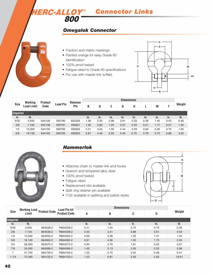
®
Hammerlok
Connector LinksConnector Links
Omegalok Connector
42
B D E G H L M T
in. lb. in. in. in. in. in. in. in. in. lb.9/32 3,500 644128 595780 602326 1.36 2.30 0.98 2.81 0.33 0.36 1.45 0.43 0.40
3/8 7,100 644138 595781 495821 1.90 2.82 1.25 3.57 0.45 0.51 1.77 0.57 1.02
1/2 12,000 644150 595782 495822 2.31 3.52 1.56 4.44 0.59 0.63 2.26 0.70 1.92
5/8 18,100 644162 595785 495823 2.87 4.46 2.00 5.45 0.75 0.78 2.72 0.88 3.20
Imperial
Size Working Load Limit WeightLoad PinProduct
CodeRetainer
Pin
Dimensions
L PIN
M
B
H
D
E
G
• Fraction and metric markings• Painted orange for easy Grade 80
identification• 100% proof tested• Fatigue rated to Grade 80 specifications• For use with master link w/flats
A B C D
in. lb. in. in. in. in. lb.9/32 3,500 664028-2 R664028-2 0.31 1.94 0.75 0.70 0.26
3/8 7,100 664038-2 R664038-2 0.50 2.41 0.88 0.91 0.59
1/2 12,000 664050-2 R664050-2 0.69 3.38 1.25 1.41 1.42
5/8 18,100 664062-2 R664062-2 0.81 4.06 1.50 1.70 2.35
3/4 28,300 664075-2 R664075-2 0.94 4.78 1.81 2.02 3.67
7/8 34,200 664089-2 R664089-2 1.05 5.13 2.00 2.25 5.98
1 47,700 664100-2 R664100-2 1.25 5.75 2.25 2.08 9.47
1 1/4 72,300 664125-2 R664125-2 1.53 6.81 2.63 2.92 16.61
Imperial
WeightSize Working Load Limit Product Code
DimensionsLoad Pin kit
Product Code
A
B
C
D
• Attaches chain to master link and hooks• Quench and tempered alloy steel• 100% proof tested• Fatigue rated• Replacement kits available• Split ring retainer pin available• 7/32 available in splitring and patlok styles

Sling HooksSling Hooks
Eye Sling Hook
Clevlok Sling Hook
43
Ove
rhea
d L
iftin
g
D G H I L M O P R
in. lb. in. in. in. in. in. in. in. in. in. lb.9/32 3,500 657318 557318 4X455322 3.53 5.23 0.38 0.75 0.36 0.83 1.00 1.11 3.44 1.20
3/8 7,100 657319 557319 4X455325 4.38 6.53 0.47 0.97 0.51 1.06 1.16 1.36 4.32 2.21
1/2 12,000 657320 557320 4X455328 5.48 8.03 0.58 1.18 0.63 1.38 1.50 1.61 5.35 4.22
5/8 18,100 657321 557321 4X455329 6.20 8.43 0.71 1.44 0.75 1.69 1.74 1.92 6.12 6.64
3/4 28,300 657322 553322 4X455330 7.09 10.80 0.88 1.81 0.94 2.09 2.00 2.08 7.25 11.22
Imperial
Size Working Load Limit
Weight w/o latch
DimensionsProduct Code w/o
latch
Product Code w/
latchLatch Kit
M (MIN)
M (MIN)
I
O
D
P
R
L
H
G
P
H
G
D
R
L
• Available with and without a latch• Quench and tempered alloy steel• CM’s clevlok head design• 100% proof tested• Fatigue rated• Replacement pin and latch kit
available• Improved forged latch• New CE compliant hooks and latches• Meets EN 1677
B D E G H I K L M N O P S
in. lb. in. in. in. in. in. in. in. in. in. in. in. in. in. lb.7/32 2,100 558544 458544 595461 -- 3.31 1.44 4.30 .38 .78 1.25 .75 3.06 1.25 1.00 .86 1.11 0.66
9/32 3,500 558322 458722 595523 1.63 3.50 1.50 5.25 .44 .73 1.59 .75 3.75 1.19 1.20 1.05 1.06 1.10
3/8 7,100 558325 458725 595525 2.06 4.33 1.88 6.64 .56 .95 2.19 .94 4.78 1.44 1.45 1.28 1.31 1.90
1/2 12,000 558328 458728 595528 2.63 5.50 2.25 8.16 .75 1.17 2.56 1.13 5.69 1.78 1.94 1.66 1.63 4.30
5/8 18,100 558329 458729 595529 3.06 6.34 2.63 9.66 .88 1.44 2.63 1.31 6.50 2.03 2.38 2.19 1.75 7.30
3/4 28,300 558330 458730 595530 3.50 7.83 3.00 11.38 1.00 1.69 3.44 1.50 7.81 2.50 2.83 2.51 2.19 12.50
7/8 34,200 558332 458732 595532 3.88 8.59 3.38 12.72 1.09 1.94 3.88 1.69 8.75 2.78 3.22 2.84 2.38 18.10
1 47,700 558333 458733 595533 4.31 9.59 4.00 14.23 1.22 2.14 4.25 1.88 9.88 3.13 3.55 3.09 2.88 22.60
1-1/4 72,300 558335 458735 595535 5.31 11.56 4.66 17.00 1.50 2.62 4.64 2.31 11.50 3.88 4.25 3.89 3.41 47.00
Imperial
SizeWorking
Load Limit
Weight w/o
latch
DimensionsProduct Code w/o
latch
Product Code w/
latchLatch Kit
B
N
G
K
D
E
P
M
I
O
L
H
S
• Available with and without latch• Quench and tempered alloy steel• 100% proof tested• Fatigue rated• Replacement latch available

®
Clevlok Cradle Grab Hook
Grab HooksGrab Hooks
Clevlok Grab Hook
44
B D E G H K L M P T
in. lb. in. in. in. in. in. in. in. in. in. in. lb.9/32 3,500 659232 595780 602326 1.36 1.91 0.36 3.70 0.33 1.04 0.36 2.29 0.76 0.81 0.6
3/8 7,100 659235 595781 495821 1.90 2.78 0.47 4.81 0.45 1.49 0.51 2.87 1.03 1.06 1.3
1/2 12,000 659238 595782 495822 2.31 3.62 0.59 6.35 0.59 1.98 0.63 3.78 1.51 1.38 2.5
5/8 18,100 659239 595783 495823 2.87 4.41 0.75 7.74 0.75 2.39 0.75 4.82 1.80 1.69 4.4
Imperial
Size Working Load Limit Weight
DimensionsLoad PinProduct
Code Retainer
Pin
B
P
H
E
K
D
EMG
L
T
• Quench and tempered alloy steel• Fatigue rated• Replacement pin available• Built without lugs to avoid catching when
slipping into tight clearance
B D E G H K L M P T
in. lb. in. in. in. in. in. in. in. in. in. in. lb.9/32 3,500 659222 1.31 1.78 .359 3.00 0.33 0.98 0.36 1.63 0.72 1.19 0.44
3/8 7,100 659225 1.81 2.56 .469 4.08 0.45 1.41 0.51 2.11 1.06 1.75 1.18
1/2 12,000 659228 2.16 3.25 .594 5.27 0.59 1.88 0.63 2.88 1.28 2.13 2.70
5/8 18,100 659229 2.69 4.08 .750 6.53 0.75 2.38 0.75 3.56 1.59 2.50 4.60
3/4 28,300 659430 3.09 4.91 .875 7.88 0.88 2.84 0.91 5.50 1.88 3.13 10.24
Imperial
Product CodeSize Working
Load Limit WeightDimensions
T
G
P
K
D
E
L
M
H
B
• CM’s unique cradle grab design• Quench and tempered alloy steel• Fatigue rated• Replacement pin available
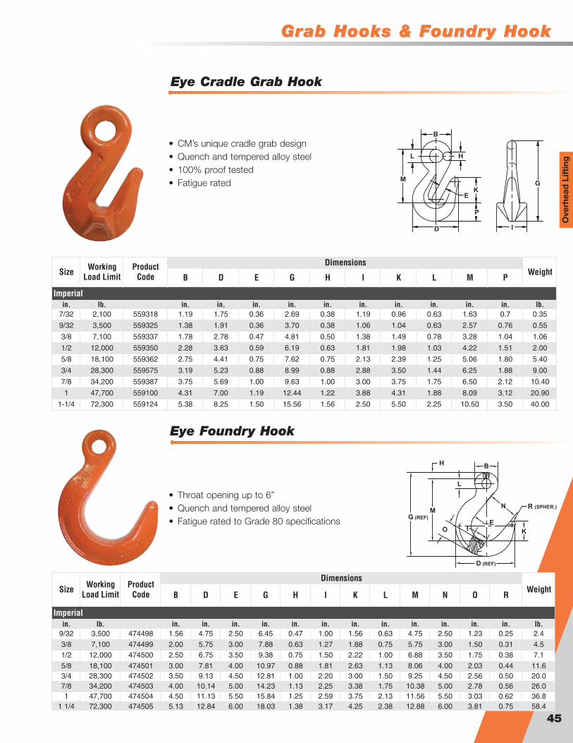
Grab Hooks & FoundrGrab Hooks & Foundry Hooky Hook
Eye Foundry Hook
Eye Cradle Grab Hook
45
Ove
rhea
d L
iftin
g
B D E G H I K L M P
in. lb. in. in. in. in. in. in. in. in. in. in. lb.7/32 2,100 559318 1.19 1.75 0.36 2.69 0.38 1.19 0.96 0.63 1.63 0.7 0.35
9/32 3,500 559325 1.38 1.91 0.36 3.70 0.38 1.06 1.04 0.63 2.57 0.76 0.55
3/8 7,100 559337 1.78 2.78 0.47 4.81 0.50 1.38 1.49 0.78 3.28 1.04 1.06
1/2 12,000 559350 2.28 3.63 0.59 6.19 0.63 1.81 1.98 1.03 4.22 1.51 2.00
5/8 18,100 559362 2.75 4.41 0.75 7.62 0.75 2.13 2.39 1.25 5.06 1.80 5.40
3/4 28,300 559575 3.19 5.23 0.88 8.99 0.88 2.88 3.50 1.44 6.25 1.88 9.00
7/8 34,200 559387 3.75 5.69 1.00 9.63 1.00 3.00 3.75 1.75 6.50 2.12 10.40
1 47,700 559100 4.31 7.00 1.19 12.44 1.22 3.88 4.31 1.88 8.09 3.12 20.90
1-1/4 72,300 559124 5.38 8.25 1.50 15.56 1.56 2.50 5.50 2.25 10.50 3.50 40.00
Imperial
Size Working Load Limit WeightProduct
Code
Dimensions
B
H
GK
E
P
D
M
L
I
• CM’s unique cradle grab design• Quench and tempered alloy steel• 100% proof tested• Fatigue rated
B D E G H I K L M N O R
in. lb. in. in. in. in. in. in. in. in. in. in. in. in. lb.9/32 3,500 474498 1.56 4.75 2.50 6.45 0.47 1.00 1.56 0.63 4.75 2.50 1.23 0.25 2.4
3/8 7,100 474499 2.00 5.75 3.00 7.88 0.63 1.27 1.88 0.75 5.75 3.00 1.50 0.31 4.51/2 12,000 474500 2.50 6.75 3.50 9.38 0.75 1.50 2.22 1.00 6.88 3.50 1.75 0.38 7.1
5/8 18,100 474501 3.00 7.81 4.00 10.97 0.88 1.81 2.63 1.13 8.06 4.00 2.03 0.44 11.63/4 28,300 474502 3.50 9.13 4.50 12.81 1.00 2.20 3.00 1.50 9.25 4.50 2.56 0.50 20.07/8 34,200 474503 4.00 10.14 5.00 14.23 1.13 2.25 3.38 1.75 10.38 5.00 2.78 0.56 26.01 47,700 474504 4.50 11.13 5.50 15.84 1.25 2.59 3.75 2.13 11.56 5.50 3.03 0.62 36.8
1 1/4 72,300 474505 5.13 12.84 6.00 18.03 1.38 3.17 4.25 2.38 12.88 6.00 3.81 0.75 58.4
WeightDimensions
Imperial
Size Working Load Limit
Product Code
H B
L
N R (SPHER.)
K
E
D (REF)
O
G (REF)
M
I
• Throat opening up to 6”• Quench and tempered alloy steel• Fatigue rated to Grade 80 specifications

®
Sorting Hook with Handle
SorSorting Hooksting Hooks
Sorting Hook
46
A B C D E F G H I M
Ton Ton in. in. in. in. in. in. in. in. in. in. lb.M129 2 7.5 3 1.44 0.78 7.34 3.75 1.28 1.25 4.13 10.09 7.38 6.8
Imperial
Product Code WLL at Tip Weight
WLL at bottom of
hook
Dimensions
I
H
C
E
G
F
D
B
MA
• Quench and tempered alloy steel• Long tapered point designed for easy grab in
rings, pear links, eyebolts or lifting holes• Painted orange• 5:1 design factor
MA
C
E
I
HGL
JKD
B
F
• Quench and tempered alloy steel• Added handle for easy removal from load• Painted orange• 5:1 design factor
A B C D E F G H I J K L M
Ton Ton in. in. in. in. in. in. in. in. in. in. in. in. in. lb.M129H 2 7.5 3 1.44 0.78 7.34 3.75 1.28 1.25 4.13 10.09 2.13 4.63 9.56 7.38 7.0
Imperial
Product Code WLL at Tip Weight
DimensionsWLL at bottom of
hook

Specialty HooksSpecialty Hooks
“S” Hook
Plate Hook
47
Ove
rhea
d L
iftin
g
in. lb. in. in. in. in. in. in. in. in. in. in. lb.9/32 462528 3,600 2.000 1.750 2.500 0.938 1.000 3.688 0.125 0.625 2.500 0.313 2.80
3/8 462537 7,050 2.625 3.000 4.313 1.188 1.125 6.375 0.188 0.750 2.750 0.375 5.70
1/2 462550 11,400 3.500 4.000 4.375 1.500 1.500 7.375 0.250 1.000 3.500 0.500 13.00
5/8 462562 17,800 4.375 5.000 5.438 1.875 1.875 9.250 0.313 1.250 5.000 0.625 26.50
3/4 462575 25,600 5.188 6.000 6.500 2.375 2.250 10.875 0.375 1.500 5.750 0.750 42.00
7/8 462587 34,900 6.000 7.000 7.625 2.500 2.625 13.062 0.438 1.750 6.000 1.000 65.00
WeightM N T W
Imperial
Size Product Code
Working Load Limit
A B C D L R
R
R
R
W
M
B
L
N
A
C
D
T
• Made from alloy material• Designed to handle plate steel• Durable orange powder coat finish• Available as components or attached to certified slings
lb. in. in. in. in. lb.562228 210 0.281 4.500 1.125 1.125 0.15
562237 410 0.375 6.000 1.500 1.500 0.35
562250 870 0.512 7.500 2.000 2.000 0.82
562262 1,120 0.625 9.000 2.500 2.500 1.56
562275 1,730 0.750 10.500 3.000 3.000 2.6
562287 2,370 0.875 12.000 3.500 3.500 4.2
562300 2,920 1.000 13.000 4.000 4.000 6.0
562310 3,150 1.125 15.000 4.500 4.500 9.3
562325 4,450 1.250 16.000 5.000 5.000 11.7
562337 6,100 1.375 17.000 5.500 5.500 15.4
562350 6,250 1.500 18.000 6.000 6.000 19.5
C D
Imperial
DimensionsWeightProduct
CodeWorking
Load Limit A B
B
C
A
C
D
• Made from alloy material• Proof tested at two times WLL• Durable orange powder coat finish• Custom sizes available upon request• WLL embossed on links• Serialized upon request

Specialty HooksSpecialty Hooks
48
MaterialsSteelBronzeStainless SteelHigh Manganese
Sizes1/4” to 2” round bar1/2” to 1-5/8” square bar1/4” x 1” to 1” x 4” flat bar
FinishesSelf-coloredZincGalvanizedPowder-coatedSilver 17
We can HOOK you up!
Our custom alloy lifting hooks are available in a wide range ofmaterials, including high manganese steel. This steel meets therigorous requirements needed in high impact and abrasionapplications.
Safety Directors and Supervisors are insisting on the use ofcertified hooks. We will provide overhead certification and prooftesting for each custom piece upon request. We can alsoserialize and tag your order.
Fabricate any hookfor any jobto your specifications
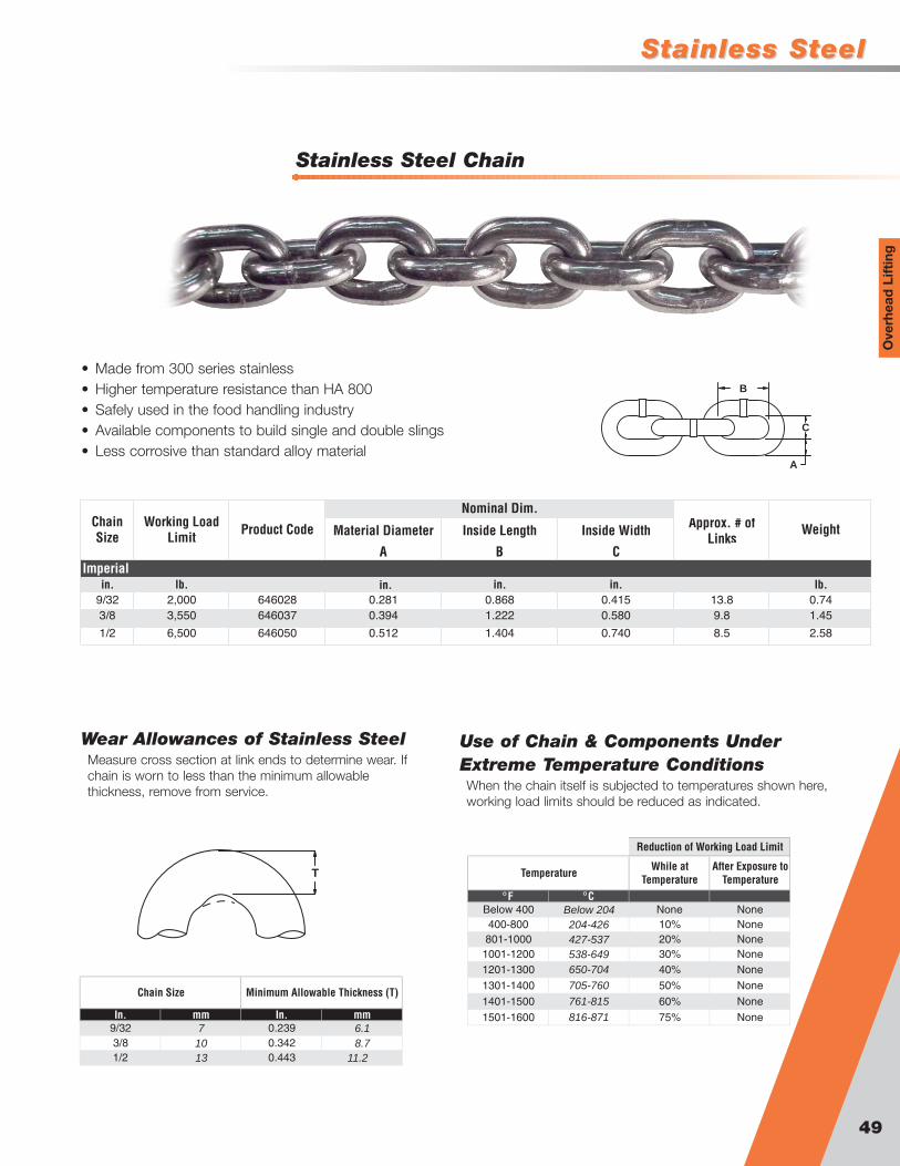
Stainless SteelStainless Steel
49
Ove
rhea
d L
iftin
g
Stainless Steel Chain
Material Diameter Inside Length Inside Width Approx. # of Links
A B C
in. lb. in. in. lb.9/32 2,000 646028 0.281 0.868 0.415 13.8 0.743/8 3,550 646037 0.394 1.222 0.580 9.8 1.45
1/2 6,500 646050 0.512 1.404 0.740 8.5 2.58
Chain Size
Working Load Limit Product Code Weight
Imperial
Nominal Dim.
in.
A
B
C
• Made from 300 series stainless• Higher temperature resistance than HA 800• Safely used in the food handling industry• Available components to build single and double slings• Less corrosive than standard alloy material
Use of Chain & Components UnderExtreme Temperature ConditionsWhen the chain itself is subjected to temperatures shown here,working load limits should be reduced as indicated.
Wear Allowances of Stainless SteelMeasure cross section at link ends to determine wear. Ifchain is worn to less than the minimum allowablethickness, remove from service.
In. mm In. mm9/32 7 0.239 6.1
1/2 13 0.443 11.23/8 10 0.342 8.7
Minimum Allowable Thickness (T)Chain Size
TWhile at
TemperatureAfter Exposure to
TemperatureF C
Below 400 Below 204 None None400-800 204-426 10% None801-1000 427-537 20% None
1001-1200 538-649 30% None1201-1300 650-704 40% None
1301-1400 705-760 50% None
1401-1500 761-815 60% None
1501-1600 816-871 75% None
Reduction of Working Load Limit
Temperature

Stainless SteelStainless Steel®
50
Material Diameter Inside Length Inside Width
A B CImperial
in. lb. in. in. lb.1/2 4,000 555550 0.500 5.00 2.50 0.793/4 7,100 555575 0.750 5.50 2.75 2.03
1 13,000 555600 1.000 7.00 3.50 4.59
Nominal Dim.Trade Size
Working Load Limit Product Code Weight
A
B
C
• Made from 300 series stainless• Retains strength in high temperatures• Designed to be used with stainless steel chain• 100% proof tested
Stainless Steel Master Link
Carb
on C
hain
Carb
on C
hain
G70 Transport Chain . . . . . . . . . . . . . . . . . . . . . . . . .52Binder Chain Specifications . . . . . . . . . . . . . . . . . . . 52G70 Welded Assembly . . . . . . . . . . . . . . . . . . . . . . . .53G70 Clevis Assembly . . . . . . . . . . . . . . . . . . . . . . . . .54G70 Rivet Assembly . . . . . . . . . . . . . . . . . . . . . . . . . .54Aircraft Assembly . . . . . . . . . . . . . . . . . . . . . . . . . . .55AG Safety Chain . . . . . . . . . . . . . . . . . . . . . . . . . . . . .55G,T,R,S Cluster Assembly . . . . . . . . . . . . . . . . . . . . . .56G,T,S Cluster Assembly . . . . . . . . . . . . . . . . . . . . . . .56G,R Cluster Assembly . . . . . . . . . . . . . . . . . . . . . . . .57“J” Hook Recovery Assembly . . . . . . . . . . . . . . . . . .57Mini “J” Hook . . . . . . . . . . . . . . . . . . . . . . . . . . . . . . .58“R” Hook . . . . . . . . . . . . . . . . . . . . . . . . . . . . . . . . . .58“T” Hook . . . . . . . . . . . . . . . . . . . . . . . . . . . . . . . . . . .59“J” Hook . . . . . . . . . . . . . . . . . . . . . . . . . . . . . . . . . . 59G70 Clevis Grab . . . . . . . . . . . . . . . . . . . . . . . . . . . . .60G70 Eye Grab Hook . . . . . . . . . . . . . . . . . . . . . . . . . .60G70 Clevis Slip Hook . . . . . . . . . . . . . . . . . . . . . . . . .61G70 Eye Slip Hook . . . . . . . . . . . . . . . . . . . . . . . . . . .61Lever Type Load Binder . . . . . . . . . . . . . . . . . . . . . . .62Claw Hook Load Binder . . . . . . . . . . . . . . . . . . . . . . .62Ratchet Type Load Binder . . . . . . . . . . . . . . . . . . . . .63Tightener Load Binder . . . . . . . . . . . . . . . . . . . . . . . .63Specialty Forged Lever Load Binder . . . . . . . . . . . . .64Removable Handle Load Binder . . . . . . . . . . . . . . . .64“E-Z PRO” Cam Release Lever Binder . . . . . . . . . . .65G43 Chain . . . . . . . . . . . . . . . . . . . . . . . . . . . . . . . . . .66G43 Hanger Chain . . . . . . . . . . . . . . . . . . . . . . . . . . .66G43 Welded Assembly . . . . . . . . . . . . . . . . . . . . . . . .67G43 Clevis Assembly . . . . . . . . . . . . . . . . . . . . . . . . .67G43 Clevis Slip with Latch . . . . . . . . . . . . . . . . . . . .68G43 Clevis Slip (Zinc) . . . . . . . . . . . . . . . . . . . . . . . . .68G43 Clevis Slip (Red) . . . . . . . . . . . . . . . . . . . . . . . . .69G43 Eye Slip Hook with Latch . . . . . . . . . . . . . . . . . .69G43 Eye Slip Hook (Zinc) . . . . . . . . . . . . . . . . . . . . . .70G43 Eye Slip Hook (Red) . . . . . . . . . . . . . . . . . . . . . .70G43 Clevis Grab Hook (Zinc) . . . . . . . . . . . . . . . . . . .71G43 Clevis Grab Hook (Red) . . . . . . . . . . . . . . . . . . .71G43 Eye Grab Hook (Zinc) . . . . . . . . . . . . . . . . . . . . .72G43 Eye Grab Hook (Red) . . . . . . . . . . . . . . . . . . . . .72G30 Chain . . . . . . . . . . . . . . . . . . . . . . . . . . . . . . . . . .73G30 Hanger Chain . . . . . . . . . . . . . . . . . . . . . . . . . . .73G30 Clevis Slip Hook . . . . . . . . . . . . . . . . . . . . . . . . .74G30 Eye Slip Hook . . . . . . . . . . . . . . . . . . . . . . . . . . .74G30 Clevis Grab Hook . . . . . . . . . . . . . . . . . . . . . . . .75G30 Eye Grab Hook . . . . . . . . . . . . . . . . . . . . . . . . . .75Heavy Duty Tiedowns . . . . . . . . . . . . . . . . . . . . . . . .76
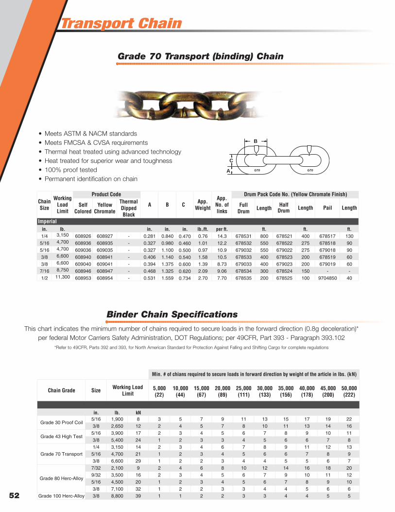
Transport Chain
Grade 70 Transport (binding) Chain
52
B
C
A
• Meets ASTM & NACM standards• Meets FMCSA & CVSA requirements• Thermal heat treated using advanced technology• Heat treated for superior wear and toughness• 100% proof tested• Permanent identification on chain
Self Colored
Yellow Chromate
Thermal Dipped Black
Full Drum Length
HalfDrum Length Pail Length
in. lb. in. in. in. lb./ft. per ft. ft. ft. ft.1/4 3,150 608926 608927 - 0.281 0.840 0.470 0.76 14.3 678531 800 678521 400 678517 130
5/16 4,700 608936 608935 - 0.327 0.980 0.460 1.01 12.2 678532 550 678522 275 678518 90
5/16 4,700 609036 609035 - 0.327 1.100 0.500 0.97 10.9 679032 550 679022 275 679018 90
3/8 6,600 608940 608941 - 0.406 1.140 0.540 1.58 10.5 678533 400 678523 200 678519 60
3/8 6,600 609040 609041 - 0.394 1.375 0.600 1.39 8.73 679033 400 679023 200 679019 60
7/16 8,750 608946 608947 - 0.468 1.325 0.620 2.09 9.06 678534 300 678524 150 - -
1/2 11,300 608953 608954 - 0.531 1.559 0.734 2.70 7.70 678535 200 678525 100 9704850 40
Drum Pack Code No. (Yellow Chromate Finish)
Imperial
B C App. Weight
App. No. of links
Chain Size
Working Load Limit
Product Code
A
5,000 10,000 15,000 20,000 25,000 30,000 35,000 40,000 45,000 50,000(22) (44) (67) (89) (111) (133) (156) (178) (200) (222)
in. lb. kN5/16 1,900 8 3 5 7 9 11 13 15 17 19 22
3/8 2,650 12 2 4 5 7 8 10 11 13 14 16
5/16 3,900 17 2 3 4 5 6 7 8 9 10 11
3/8 5,400 24 1 2 3 3 4 5 6 6 7 8
1/4 3,150 14 2 3 4 6 7 8 9 11 12 13
5/16 4,700 21 1 2 3 4 5 6 6 7 8 9
3/8 6,600 29 1 2 2 3 4 4 5 5 6 7
7/32 2,100 9 2 4 6 8 10 12 14 16 18 20
9/32 3,500 16 2 3 4 5 6 7 9 10 11 12
5/16 4,500 20 1 2 3 4 5 6 7 8 9 10
3/8 7,100 32 1 2 2 3 3 4 4 5 6 6
Grade 100 Herc-Alloy 3/8 8,800 39 1 1 2 2 3 3 4 4 5 5
Grade 70 Transport
Grade 80 Herc-Alloy
Min. # of chians required to secure loads in forward direction by weight of the article in lbs. (kN)
Grade 30 Proof Coil
Grade 43 High Test
Working Load LimitSizeChain Grade
Binder Chain SpecificationsThis chart indicates the minimum number of chains required to secure loads in the forward direction (0.8g deceleration)*
per federal Motor Carriers Safety Administration, DOT Regulations; per 49CFR, Part 393 - Paragraph 393.102*Refer to 49CFR, Parts 392 and 393, for North American Standard for Protection Against Falling and Shifting Cargo for complete regulations
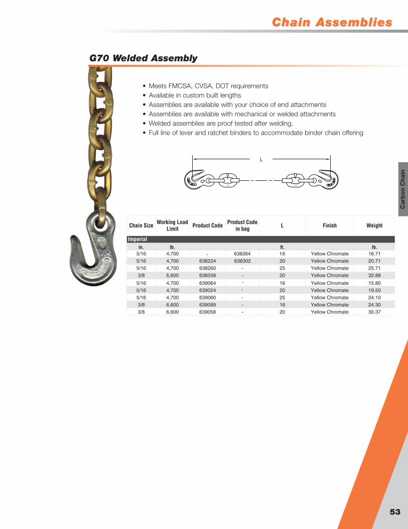
Chain AssembliesChain Assemblies
G70 Welded Assembly
L
• Meets FMCSA, CVSA, DOT requirements• Available in custom built lengths• Assemblies are available with your choice of end attachments • Assemblies are available with mechanical or welded attachments• Welded assemblies are proof tested after welding.• Full line of lever and ratchet binders to accommodate binder chain offering
Chain Size Working Load Limit Product Code Product Code
in bag L Finish Weight
in. lb. ft. lb.5/16 4,700 638264 16 Yellow Chromate 16.71
5/16 4,700 638224 638302 20 Yellow Chromate 20.71
5/16 4,700 638260 - 25 Yellow Chromate 25.71
3/8 6,600 638558 - 20 Yellow Chromate 32.88
5/16 4,700 639064 16 Yellow Chromate 15.80
5/16 4,700 639024 20 Yellow Chromate 19.50
5/16 4,700 639060 - 25 Yellow Chromate 24.10
3/8 6,600 639089 - 16 Yellow Chromate 24.30
3/8 6,600 639058 - 20 Yellow Chromate 30.37
Imperial
-
-
-
53
Car
bo
n C
hain

Transport Chain Chain AssembliesChain Assemblies
G70 Clevis Assembly
54
L
L
Chain Size Working Load Limit
Product Code Bulk
Product Code in bag L Finish Weight
in. lb. ft. lb.
1/4 3,150 638265 - 20 Yellow Chromate 15.40
5/16 4,700 638274 - 12 Yellow Chromate 13.10
5/16 4,700 638281 638276 14 Yellow Chromate 15.10
5/16 4,700 638282 638277 16 Yellow Chromate 17.10
5/16 4,700 638283 - 18 Yellow Chromate 19.10
5/16 4,700 638284 638266 20 Yellow Chromate 21.10
5/16 4,700 638313 - 24 Yellow Chromate 25.10
5/16 4,700 638279 638279BG 25 Yellow Chromate 26.10
3/8 6,600 638291 - 14 Yellow Chromate 23.50
3/8 6,600 638292 638268 16 Yellow Chromate 26.60
3/8 6,600 638293 - 18 Yellow Chromate 29.80
3/8 6,600 638294 638267 20 Yellow Chromate 32.90
1/2 11,300 638350 - 20 Yellow Chromate 54.20
5/16 4,700 639081 - 14 Yellow Chromate 13.90
5/16 4,700 639082 - 16 Yellow Chromate 15.80
5/16 4,700 639083 - 18 Yellow Chromate 17.60
5/16 4,700 639084 639084BG 20 Yellow Chromate 19.40
5/16 4,700 639013 - 24 Yellow Chromate 23.10
5/16 4,700 639079 639079BG 25 Yellow Chromate 24.00
3/8 6,600 639091 - 14 Yellow Chromate 21.76
3/8 6,600 639092 639068 16 Yellow Chromate 24.56
3/8 6,600 639093 - 18 Yellow Chromate 27.36
3/8 6,600 639094 639094BG 20 Yellow Chromate 30.16
3/8 6,600 639097 - 25 Yellow Chromate 30.16
Imperial
Standard Link
Short Link
G70 Rivet Assembly
Chain Size Working Load Limit Product Code L Finish Weight
in. lb. ft. lb.
5/16 4,700 638281 CRV 14 Yellow Chromate 15.10
5/16 4,700 638282CRV 16 Yellow Chromate 17.10
5/16 4,700 638283 CRV 18 Yellow Chromate 19.10
5/16 4,700 638284CRV 20 Yellow Chromate 21.10
3/8 6,600 638291CRV 14 Yellow Chromate 23.50
3/8 6,600 638292CRV 16 Yellow Chromate 26.60
3/8 6,600 638293CRV 18 Yellow Chromate 29.80
3/8 6,600 638294CRV 20 Yellow Chromate 32.90
5/16 4,700 639084CRV 20 Yellow Chromate 21.10
5/16 4,700 639079CRV 25 Yellow Chromate 24.00
3/8 6,600 639094CRV 20 Yellow Chromate 30.20
Imperial
Standard Link
Short Link
• Meets all Department of Transportationrequirements
• No worries with ultra-violet degrading• Custom lengths available• Required in most states by DOT
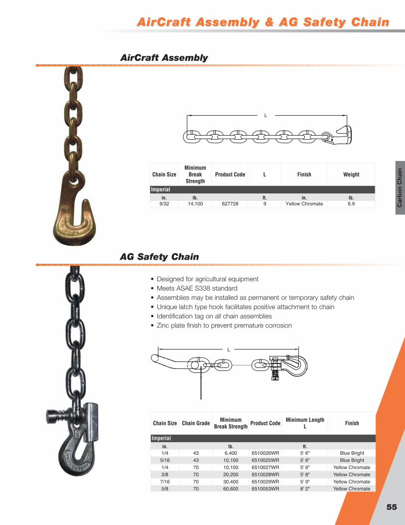
AirCraft Assembly & AG Safety ChainAirCraft Assembly & AG Safety Chain
AG Safety Chain
AirCraft Assembly
55
Car
bo
n C
hain
L
• Designed for agricultural equipment• Meets ASAE S338 standard• Assemblies may be installed as permanent or temporary safety chain• Unique latch type hook facilitates positive attachment to chain• Identification tag on all chain assemblies• Zinc plate finish to prevent premature corrosion
Chain SizeMinimum
Break Strength
Product Code L Finish Weight
in. lb. ft. in. lb.9/32 14,100 627728 9 Yellow Chromate 6.9
Imperial
Chain Size Chain Grade Minimum Break Strength Product Code Minimum Length
L Finish
in. lb. ft.1/4 43 6,400 6510026WR 5' 6" Blue Bright
5/16 43 10,100 6510025WR 5' 6" Blue Bright
1/4 70 10,100 6510027WR 5' 6" Yellow Chromate
3/8 70 20,200 6510028WR 5' 8" Yellow Chromate
7/16 70 30,400 6510029WR 5' 9" Yellow Chromate5/8 70 60,600 6510053WR 8' 2" Yellow Chromate
Imperial
L
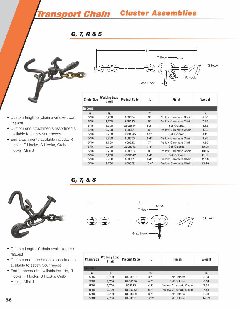
Transport Chain
G, T, & S
Cluster AssembliesCluster Assemblies
G, T, R & S
56
L
T Hook
Grab Hook
R Hook
S Hook
Chain Size Working Load Limit Product Code L Finish Weight
in. lb. lb.5/16 2,700 608324 3ʼ Yellow Chromate Chain 5.98
5/16 2,700 608320 5ʼ Yellow Chromate Chain 7.95
5/16 2,700 U608344 5ʼ2” Self Colored 8.12
5/16 2,700 608321 6ʼ Yellow Chromate Chain 8.95
5/16 2,700 U608345 6ʼ2” Self Colored 9.11
5/16 2,700 608330 6ʼ4” Yellow Chromate Chain 9.28
5/16 2,700 608322 7ʼ Yellow Chromate Chain 9.95
5/16 2,700 U608346 7ʼ4” Self Colored 10.28
5/16 2,700 608323 8ʼ Yellow Chromate Chain 10.95
5/16 2,700 U608347 8ʼ4” 11.115/16 2,700 608331 8ʼ4” Yellow Chromate Chain 11.28
5/16 2,700 608332 10ʼ4” Yellow Chromate Chain 13.28
Imperialft.
Self Colored
Chain Size Working Load Limit Product Code L Finish Weight
in. lb. lb.5/16 2,700 U608327 3’7” Self Colored 5.64
5/16 2,700 U608328 4’7” Self Colored 6.64
5/16 2,700 608333 4’8” Yellow Chromate Chain 7.31
5/16 2,700 U608332 5’7” Yellow Chromate Chain 7.64
5/16 2,700 U608330 6’7” Self Colored 8.64
5/16 2,700 U608331 12’7” Self Colored 14.63
Imperialft.
L
T Hook
Grab Hook
S Hook
• Custom length of chain available uponrequest
• Custom end attachments assortmentsavailable to satisfy your needs
• End attachments available include, RHooks, T Hooks, S Hooks, GrabHooks, Mini J
• Custom length of chain available uponrequest
• Custom end attachments assortmentsavailable to satisfy your needs
• End attachments available include, RHooks, T Hooks, S Hooks, GrabHooks, Mini J

Cluster AssembliesCluster Assemblies
Recovery J Hook Assemblies
G & R
57
Car
bo
n C
hain
Chain Size Working Load Limit Product Code L Finish Weight
in. lb. lb.5/16 4,700 U608329 8 Self Colored 9.64
5/16 4,700 U608356 6 Self Colored 7.64
5/16 4,700 U608357 5 Self Colored 6.64
5/16 4,700 U608360 10 Self Colored 11.64
Imperialft.
L
Grab Hook
R Hook
• Custom length of chain available uponrequest
• Custom end attachments assortmentsavailable to satisfy your needs
• End attachments available include, RHooks, T Hooks, S Hooks, GrabHooks, Mini J
Size Working Load Limit Product Code Chain Length Description
in. lb. ft.3/8 7,100 97901G8 10 Omegalok and Master Link3/8 7,100 97901G9 10 Clevlok Cradle Grab
Imperial
• Patented I beam profile towing 15” Clevlok Alloy J Hook• Clevloc style head, no catch points• Patented nose design reduces hook slippage on chain• Load rest reduces load rolling out of hook bowl
(load must be behind rest)• Designed for the professional towing• G80 Proof Loaded Assemblies• All mechanical connections... no welded links

Transport Chain
“R” Hook
TTowing Attachmentsowing Attachments
Mini “J” Hook
58
• Designed specifically for the towing and transportindustry
• Designed for use with 5/16” grade 70 chain• Not to be used with 1/4” chain• Combinations available for all tie down needs• Finishes available are yellow chromate, Self colored
and zinc plated • Not for overhead lifting
• Designed specifically for the towing andtransport industry
• Designed for use with 5/16” grade 70chain
• Not to be used with 1/4” chain• Combinations available for all tie down
needs• Finishes available are yellow chromate,
Self colored and zinc plated • Not for overhead lifting
B
A
C
E
FD
A B C D E F
in. lb. in. in. in. in. in. in. lb.5/16 4,700 92714 92711 4.84 2.76 0.63 0.38 1.30 0.55
Imperial
WeightDimensions
SizeWorking Load
Limit (grade 70)
Product Code (Yellow
Chromate)
Product Code (Zinc)
0.60
B
A
C
E
D
A B C D E
in. lb. in. in. in. in. in. lb.5/16 4,700 93424 93423 2.72 3.40 1.50 1.13 0.53
Dimensions
Imperial
WeightSizeWorking Load
Limit (grade 70)
Product Code (Self Colored)
Product Code (Zinc)
0.64
! !WARNINGNot for overhead lifting

TTowing Attachmentsowing Attachments
“J” Hook
“T” Hook
59
Car
bo
n C
hain
• Designed specifically for the towing and transport industry• Designed for use with 5/16” grade 70 chain• Not to be used with 1/4” chain• Combinations available for all tie down needs• Finishes available are yellow chromate, Self colored and
zinc plated • Not for overhead lifting
B
A
C
E
D
A B C D E
in. lb. in. in. in. in. in. lb.5/16 4,700 93406 93405 2.50 4.00 1.64 0.50 0.63
Imperial
WeightSizeWorking Load
Limit (grade 70)
Product Code (Self Colored)
Product Code (Zinc)
Dimensions
0.62
Grade Working Load Limit Product Code Finish Description
lb.G70 4,700 92859 Yellow Chromate Forged 8" J HookG70 4,700 91259 Yellow Chromate Forged 15" J Hook
Imperial 15” 91259
8” 92859
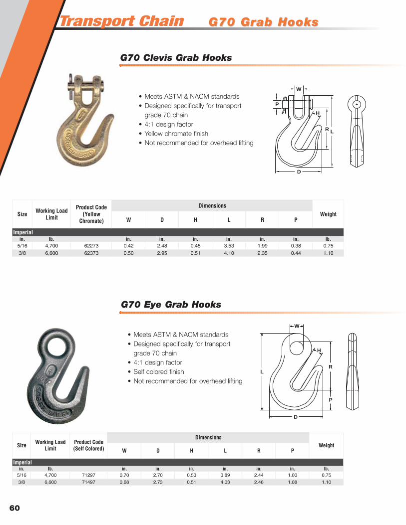
Transport Chain
G70 Eye Grab Hooks
G70 Grab HooksG70 Grab Hooks
G70 Clevis Grab Hooks
60
• Meets ASTM & NACM standards• Designed specifically for transport
grade 70 chain• 4:1 design factor• Self colored finish• Not recommended for overhead lifting
W D H L R P
in. lb. in. in. in. in. in. in. lb.5/16 4,700 62273 0.42 2.48 0.45 3.53 1.99 0.38 0.753/8 6,600 62373 0.50 2.95 0.51 4.10 2.35 0.44 1.10
Imperial
WeightDimensions
Size Working Load Limit
Product Code (Yellow
Chromate)
W D H L R P
in. lb. in. in. in. in. in. in. lb.5/16 4,700 71297 0.70 2.70 0.53 3.89 2.44 1.00 0.75
3/8 6,600 71497 0.68 2.73 0.51 4.03 2.46 1.08 1.10
Imperial
WeightDimensions
Size Working Load Limit
Product Code (Self Colored)
W
L
H
R
D
P
• Meets ASTM & NACM standards• Designed specifically for transport
grade 70 chain• 4:1 design factor• Yellow chromate finish• Not recommended for overhead lifting
H
L
W
D
P
R
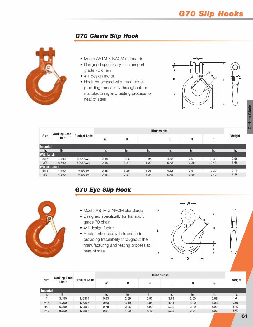
G70 Slip HooksG70 Slip Hooks
G70 Eye Slip Hook
G70 Clevis Slip Hook
61
Car
bo
n C
hain
H
L
D
W
P
R
• Meets ASTM & NACM standards• Designed specifically for transport
grade 70 chain• 4:1 design factor• Hook embossed with trace code
providing traceability throughout themanufacturing and testing process toheat of steel
W D H L R P
in. lb. in. in. in. in. in. in. lb.
5/16 4,700 6905AWL 0.38 3.25 0.94 4.62 2.91 0.393/8 6,600 6906AWL 0.45 3.87 1.00 5.42 3.39 0.49
5/16 4,700 M6905A 0.38 3.25 1.06 4.62 2.91 0.393/8 6,600 M6906A 0.45 3.87 1.24 5.42 3.39 0.49
With Latch
Without Latch
Imperial
WeightDimensions
Size Working Load Limit Product Code
0.961.66
0.751.25
• Meets ASTM & NACM standards• Designed specifically for transport
grade 70 chain• 4:1 design factor• Hook embossed with trace code
providing traceability throughout themanufacturing and testing process toheat of steel
H
L
W
D
G
R
W D H L R G
in. lb. in. in. in. in. in. in. lb.1/4 3,150 M6304 0.53 2.69 0.90 3.79 2.60 0.88
5/16 4,700 M6305 0.63 3.19 1.05 4.41 3.00 1.033/8 6,600 M6306 0.78 3.75 1.22 5.38 3.72 1.257/16 8,750 M6307 0.81 4.33 1.46 5.75 3.91 1.38
Imperial
WeightDimensions
Size Working Load Limit Product Code
0.45
0.581.401.50

Binders
Claw Hook Load Binder
Lever Type Load Binder
62
• All components are forged, no castparts
• Forged binders are lighter and strongerthan cast binders
• Under equal force a forged handle willyield and bend while a cast handlemay break
G30 G43 G70 G80
in. in. in. in. lb. in. in. lb.1/4 1/4 - - 48304 2,600 3.75 11.25 3.0
3/8 3/8 5/16 - 48305 5,400 4.50 16.12 8.1
1/2 1/2 3/8 - 48406 9,200 4.75 16.62 10.6
3/8 3/8 3/8 3/8 48769 7,100 4.50 16.62 8.1
Weight
Imperial
SizeWorking Load
LengthProduct Code Working Load Limit Handle Take Up
G43 G70
in. in. lb. in. in. lb.3/8 - Special Order 5,400 4.50 16.12 0.69
- 3/8 Special Order 9,200 4.75 16.62 1.00
3/8 3/8 Special Order 6,600 4.50 16.62 2.02
Size
Imperial
WeightWorking Load LengthProduct Code Working Load Limit Handle Take Up
! !WARNINGLoad binding systems store energy which can release suddenly
To avoid injury:Operate only by hand from a firm standing position. Operate handle cautiously. Stay clear of handle path: handle may release suddenly. Follow instructions.
Load binder operating instructions
1. Follow D.O.T. Federal Motor Carrier Safety RegulationsS 392.9, S 393.100, and S 393.102
2. Inspect before use. Replace worn and deformedbinders. Lubricate pivot and swivel points for optimumperformance.
3. Do not operate with anyone on load.
4. Always apply lever binder in straight line hook to hookmanner without bending and such that handle goesdown when securing load.
5. Tighten binders before moving and recheck frequently.
6. Do not exceed working load limit shown on binder - handeffort will tighten binder to working load limit.
7. Do not use cheater bar or handle extension as their usecan overload binder system and result in injury.
8. Secure handle down with a positive retaining method.
9. Release handle/load with extreme care. Make sureeveryone is clear. Lever binder handle can snap backover center. Use open palm under handle and push up.
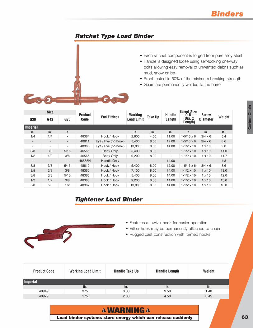
BindersBinders
Tightener Load Binder
Ratchet Type Load Binder
63
Car
bo
n C
hain
• Each ratchet component is forged from pure alloy steel• Handle is designed loose using self-locking one-way
bolts allowing easy removal of unwanted debris such asmud, snow or ice
• Proof tested to 50% of the minimum breaking strength• Gears are permanently welded to the barrel
G30 G43 G70
in. in. in. lb. in. in. in. in. lb.1/4 1/4 - 48364 Hook / Hook 2,600 4.00 11.00 1-5/16 x 6 3/4 x 6 5.4
- - - 48811 Eye / Eye (no hook) 5,400 8.00 12.00 1-5/16 x 6 3/4 x 6 8.6
- - - 48363 Eye / Eye (no hook) 13,000 8.00 14.00 1-1/2 x 10 1 x 10 9.8
3/8 3/8 5/16 46565 Body Only 5,400 8.00 - 1-1/2 x 10 1 x 10 11.0
1/2 1/2 3/8 46566 Body Only 9,200 8.00 - 1-1/2 x 10 1 x 10 11.7
- - - 46565H Handle Only - - 14.00 - - 4.3
3/8 3/8 5/16 48810 Hook / Hook 5,400 8.00 12.00 1-5/16 x 6 3/4 x 6 8.6
3/8 3/8 3/8 48360 Hook / Hook 7,100 8.00 14.00 1-1/2 x 10 1 x 10 13.0
3/8 3/8 5/16 48365 Hook / Hook 5,400 8.00 14.00 1-1/2 x 10 1 x 10 12.0
1/2 1/2 3/8 48366 Hook / Hook 9,200 8.00 14.00 1-1/2 x 10 1 x 10 13.0
5/8 5/8 1/2 48367 Hook / Hook 13,000 8.00 14.00 1-1/2 x 10 1 x 10 16.0
Weight
Imperial
SizeEnd Fittings Working
Load Limit
Barrel Size
(Dia. x Length)
Screw Diameter
Product Code Take Up Handle
LengthO.D.
lb. in. in. lb.48949 375 3.00 9.50 1.40
48979 175 2.00 4.50 0.45
Imperial
WeightHandle LengthProduct Code Working Load Limit Handle Take Up
• Features a swivel hook for easier operation• Either hook may be permanently attached to chain• Rugged cast construction with formed hooks
! !WARNINGLoad binder systems store energy which can release suddenly

Binders
Specialty Forged Lever Load Binder
64
• DIXI-LOC (48385) binders provide extra security byallow the binder to be locked in closed positionusing a pad lock, linch pin or bolt.
• COMPRESSION BINDERS (48758 & 48395) aredesigned for securing bar and rod steel, lumber,poles and machinery with rubber tires.
• EZ GRAB (48325) is a military style binder designedto use the handle leverage to remove slack from thechain before hook-up, achieving correct tension onthe first try.
• Removing handle provides greater load security by making itless likely for load to be stolen
• Reduces overall weight
G30 G43 G70
in. in. in. lb. in. in. lb.3/8 3/8 5/16 48385 5,400 4.50 16.62 8.50
3/8 3/8 5/16 48395 5,400 4.50 16.62 14.60
1/2 1/2 3/8 48758 9,200 4.50 16.62 13.00
3/8 3/8 5/16 48325 5,400 4.50 18.38 8.75
Weight
Imperial
SizeHandle LengthProduct Code Working Load
Limit Take Up
G30 G43 G70
in. in. in. lb. in. in. lb.3/8 3/8 5/16 46565 Body 5,400 8.00 - 7.4
1/2 1/2 3/8 46566 Body 9,200 8.00 - 11.7
- - - 46565H Handle - - 14 4.3
Weight
Imperial
SizeHandle LengthProduct Code Working Load
Limit Handle Take Up
Removable Handle Load Binder
! !WARNINGLoad binder systems store energy which can release suddenly
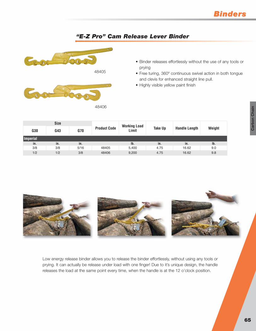
BindersBinders
“E-Z Pro” Cam Release Lever Binder
65
Car
bo
n C
hain
• Binder releases effortlessly without the use of any tools orprying
• Free turing, 360º continuous swivel action in both tongueand clevis for enhanced straight line pull.
• Highly visible yellow paint finish
G30 G43 G70
in. in. in. lb. in. in. lb.3/8 3/8 5/16 48405 5,400 4.75 16.62 9.0
1/2 1/2 3/8 48406 9,200 4.75 16.62 9.8
Weight
Imperial
SizeHandle LengthProduct Code Working Load
Limit Take Up
Low energy release binder allows you to release the binder effortlessly, without using any tools orprying. It can actually be release under load with one finger! Due to it’s unique design, the handlereleases the load at the same point every time, when the handle is at the 12 o’clock position.
48405
48406

Carbon Chain Chain & AssembliesChain & Assemblies
G43 Chain
66
Gr-43, commonly called High Test, is manufactured to meet ASTM & NACM specifications. Typical usesinclude container securement, logging, towing, and marine industry. Gr-43 is available in many finishes andpackage configurations. "Gr-43 is not to be used for overhead lifting".
G43 Hanger Chain
Chain Size
Full Drum
Length Half Drum
Length Pail Length Full Drum
Length Half Drum
Length Pail Full Drum
Half Drum
Length
in. ft. ft. ft. ft. ft. ft. ft. ft.1/4 678141 800 678131 400 678111 140 678441 800 678431 400 678411 140 678341 800 678331 400
5/16 678142 550 678132 275 678112 90 678442 550 678432 275 678412 90 678342 550 678332 275
3/8 678143 400 678133 200 678113 60 678443 400 678433 200 678413 60 678343 400 678333 200
1/2 - 350 678145 200 - - 678445 200 - 100 - - 678345 200 - 100
5/8 678146 150 678136 75 - - - 150 - 75 - - 678346 150 678336 75
3/4 678147 100 678137 50 - - - 100 - 50 - - 678347 100 678337 50
Zinc Plated Finish Hot Dipped Galvanized FinishSelf Colored Finish
Imperial
Length Length
• Meets ASTM & NACM standards• Available in a wide assortment of finishes including, Self Colored,
Burnished, Zinc Plated, Galvanized• 50% stronger than Gr-30 Chain• Permanent identification on chain• 100% proof tested• Available in drums, pails, multiple style of assemblies
B
C
A
Chain Size Working Load Limit Product Code L Finish Weight
in. lb. ft. lb.1/4 2,600 628204GA 4 Self Colored 2.91/4 2,600 628209GA 9 Self Colored 5.8
1/4 2,600 628212GA 12 Self Colored 7.7
3/8 5,400 628311GA 11 Self Colored 15.9
Imperial
L
in. lb. in. in. in. lb.1/4 2,600 0.270 1.220 0.460 0.60 9.84
5/16 3,900 0.327 1.100 0.500 0.98 10.91
3/8 5,400 0.386 1.370 0.600 1.33 8.76
1/2 9,200 0.500 1.730 0.810 2.27 6.93
5/8 13,000 0.625 1.916 0.855 3.63 5.63
3/4 20,200 0.781 2.397 1.070 5.68 5.66
A B C
Imperial
App. No of Links
Chain Size
Working Load Limit
App. Weight
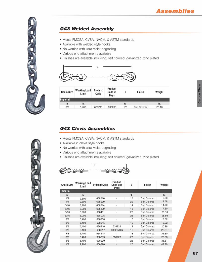
AssembliesAssemblies
G43 Welded Assembly
67
Car
bo
n C
hain
• Meets FMCSA, CVSA, NACM, & ASTM standards• Available with welded style hooks• No worries with ultra-violet degrading• Various end attachments available• Finishes are available including; self colored, galvanized, zinc plated
L
Chain Size Working Load Limit
Product Code
Product Code in
BagsL Finish Weight
in. lb. ft. lb.3/8 5,400 638241 638238 20 Self Colored 28.10
Imperial
L
• Meets FMCSA, CVSA, NACM, & ASTM standards• Available in clevis style hooks• No worries with ultra-violet degrading• Various end attachments available• Finishes are available including; self colored, galvanized, zinc plated
G43 Clevis Assemblies
Chain Size Working Load Limit Product Code
Product Code Bag
PackL Finish Weight
in. lb. ft. lb.1/4 638010 - 10 Self Colored 6.50
1/4 2,600 638020 - 20 Self Colored 12.58
5/16 3,900 608014 - 14 Self Colored 14.70
5/16 3,900 638209 - 16 Self Colored 17.80
5/16 3,900 608401 - 20 Self Colored 21.10
5/16 3,900 638025 - 25 Self Colored 25.50
3/8 5,400 638208 - 10 Self Colored 18.32
3/8 5,400 638215 - 12 Self Colored 18.32
3/8 5,400 638216 638222 14 Self Colored 20.98
3/8 5,400 638217 638217BG 16 Self Colored 23.64
3/8 5,400 638218 - 18 Self Colored 26.30
3/8 5,400 638219 638223 20 Self Colored 28.96
3/8 5,400 638220 - 25 Self Colored 35.61
1/2 9,200 638226 - 20 Self Colored 47.70
Imperial
2,600
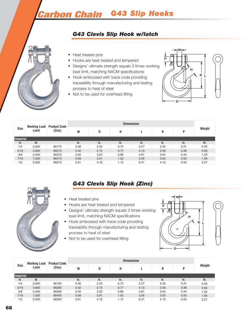
G43 Clevis Slip Hook (Zinc)
G43 Clevis Slip Hook w/latch
G43 Slip HooksG43 Slip Hooks
68
• Heat treated pins• Hooks are heat treated and tempered• Designs’ ultimate strength equals 3 times working
load limit, matching NACM specifications• Hook embossed with trace code providing
traceability through manufacturing and testingprocess to heat of steel
• Not to be used for overhead lifting
H
L
W
R
D
P
W D H L R P
in. lb. in. in. in. in. in. in. lb.1/4 2,600 66173 0.36 2.33 0.72 2.27 2.32 0.31
5/16 3,900 66273 0.42 2.72 0.77 4.13 2.56 0.383/8 5,400 66373 0.50 3.20 0.86 4.81 3.04 0.447/16 7,200 66473 0.58 3.91 1.02 5.56 3.50 0.501/2 9,200 66573 0.61 4.16 1.12 6.31 4.15 0.55
Imperial
WeightDimensions
Size Working Load Limit
Product Code (Zinc)
0.35
0.631.021.562.27
• Heat treated pins• Hooks are heat treated and tempered• Designs’ ultimate strength equals 3 times working
load limit, matching NACM specifications• Hook embossed with trace code providing
traceability through manufacturing and testingprocess to heat of steel
• Not to be used for overhead lifting
H
L
W
R
D
P
W D H L R P
in. lb. in. in. in. in. in. in. lb.1/4 2,600 66193 0.36 2.33 0.72 2.27 2.32 0.31
5/16 3,900 66293 0.42 2.72 0.77 4.13 2.56 0.383/8 5,400 66393 0.50 3.20 0.86 4.81 3.04 0.447/16 7,200 66493 0.58 3.91 1.02 5.56 3.50 0.501/2 9,200 66593 0.61 4.16 1.12 6.31 4.15 0.55
Imperial
WeightDimensions
Size Working Load Limit
Product Code (Zinc)
0.35
0.631.021.562.27
Carbon Chain
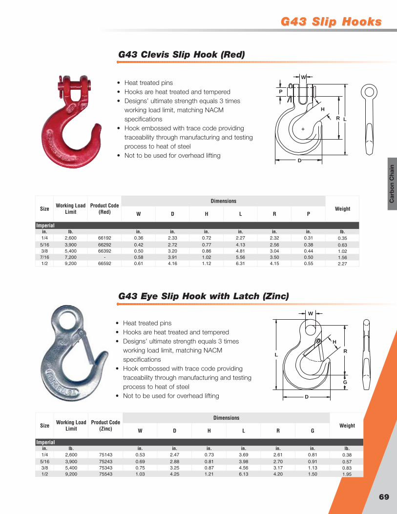
G43 Slip HooksG43 Slip Hooks
69
Car
bo
n C
hain
G43 Eye Slip Hook with Latch (Zinc)
G43 Clevis Slip Hook (Red)
• Heat treated pins• Hooks are heat treated and tempered• Designs’ ultimate strength equals 3 times
working load limit, matching NACMspecifications
• Hook embossed with trace code providingtraceability through manufacturing and testingprocess to heat of steel
• Not to be used for overhead lifting
• Heat treated pins• Hooks are heat treated and tempered• Designs’ ultimate strength equals 3 times
working load limit, matching NACMspecifications
• Hook embossed with trace code providingtraceability through manufacturing and testingprocess to heat of steel
• Not to be used for overhead lifting
H
L
W
R
D
P
W D H L R P
in. lb. in. in. in. in. in. in. lb.1/4 2,600 66192 0.36 2.33 0.72 2.27 2.32 0.31
5/16 3,900 66292 0.42 2.72 0.77 4.13 2.56 0.383/8 5,400 66392 0.50 3.20 0.86 4.81 3.04 0.447/16 7,200 - 0.58 3.91 1.02 5.56 3.50 0.501/2 9,200 66592 0.61 4.16 1.12 6.31 4.15 0.55
Imperial
WeightDimensions
Size Working Load Limit
Product Code (Red)
0.35
0.631.021.562.27
H
L
W
R
D
G
W D H L R G
in. lb. in. in. in. in. in. in. lb.1/4 2,600 75143 0.53 2.47 0.73 3.69 2.61 0.81
5/16 3,900 75243 0.69 2.88 0.81 3.98 2.70 0.913/8 5,400 75343 0.75 3.25 0.87 4.56 3.17 1.131/2 9,200 75543 1.03 4.25 1.21 6.13 4.20 1.50
Imperial
WeightDimensions
Size Working Load Limit
Product Code (Zinc)
0.38
0.570.831.95

Carbon Chain G43 Slip HooksG43 Slip Hooks
70
G43 Eye Slip Hook (Red)
G43 Eye Slip Hook (Zinc)
• Heat treated pins• Hooks are heat treated and tempered• Designs’ ultimate strength equals 3 times
working load limit, matching NACMspecifications
• Hook embossed with trace code providingtraceability through manufacturing and testingprocess to heat of steel
• Not to be used for overhead lifting
• Heat treated pins• Hooks are heat treated and tempered• Designs’ ultimate strength equals 3 times
working load limit, matching NACMspecifications
• Hook embossed with trace code providingtraceability through manufacturing and testingprocess to heat of steel
• Not to be used for overhead lifting
H
L
W
G
D
R
W D H L R G
in. lb. in. in. in. in. in. in. lb.1/4 2,600 75193 0.53 2.47 0.81 3.69 2.61 0.81
5/16 3,900 75293 0.69 2.88 0.83 3.98 2.70 0.913/8 5,400 75393 0.75 3.25 0.92 4.56 3.17 1.137/16 7,200 75493 0.91 3.73 1.23 5.56 3.64 1.311/2 9,200 75593 1.03 4.25 1.30 6.13 4.20 1.505/8 13,000 75693 1.28 5.23 1.69 7.41 5.11 1.813/4 20,200 75793 1.36 6.28 1.98 8.88 6.00 2.34
Imperial
WeightDimensions
Size Working Load Limit
Product Code (Zinc)
0.38
0.570.831.381.953.723.72
H
L
W
G
D
R
W D H L R G
in. lb. in. in. in. in. in. in. lb.1/4 2,600 75192 0.53 2.47 0.81 3.69 2.61 0.81
5/16 3,900 75292 0.69 2.88 0.83 3.98 2.70 0.913/8 5,400 75392 0.75 3.25 0.92 4.56 3.17 1.137/16 7,200 75492 0.91 3.73 1.23 5.56 3.64 1.311/2 9,200 75592 1.03 4.25 1.30 6.13 4.20 1.505/8 13,000 75692 1.28 5.23 1.69 7.41 5.11 1.813/4 20,200 75792 1.36 6.28 1.98 8.88 6.00 2.34
Imperial
WeightDimensions
Size Working Load Limit
Product Code (Red)
0.38
0.570.831.381.953.723.72

G43 Grab HooksG43 Grab Hooks
71
Car
bo
n C
hain
G43 Clevis Grab Hook (Red)
G43 Clevis Grab Hook (Zinc)
• Heat treated pins• Hooks are heat treated and tempered• Designs’ ultimate strength equals 3 times
working load limit, matching NACMspecifications
• Hook embossed with trace code providingtraceability through manufacturing and testingprocess to heat of steel
• Not to be used for overhead lifting
• Heat treated pins• Hooks are heat treated and tempered• Designs’ ultimate strength equals 3 times
working load limit, matching NACMspecifications
• Hook embossed with trace code providingtraceability through manufacturing and testingprocess to heat of steel
• Not to be used for overhead lifting
H
L
W
R
D
P
H
L
W
R
D
P
W D H L R P
in. lb. in. in. in. in. in. in. lb.1/4 2,600 61193 0.36 2.05 0.36 3.00 1.57 0.31
5/16 3,900 61293 0.42 2.41 0.44 3.56 1.98 0.383/8 5,400 61393 0.50 2.94 0.52 4.20 2.23 0.447/16 7,200 61493 0.58 3.25 0.60 4.94 2.94 0.501/2 9,200 61593 0.66 3.70 0.67 5.20 2.93 0.55
Imperial
WeightDimensions
Size Working Load Limit
Product Code (Zinc)
0.37
0.631.101.602.42
W D H L R P
in. lb. in. in. in. in. in. in. lb.1/4 2,600 61192 0.36 2.05 0.36 3.00 1.57 0.31
5/16 3,900 61292 0.42 2.41 0.44 3.56 1.98 0.383/8 5,400 61392 0.50 2.94 0.52 4.20 2.23 0.441/2 9,200 61592 0.66 3.70 0.67 5.20 2.93 0.555/8 13,000 61692 0.78 4.38 0.83 6.50 4.06 0.63
Imperial
WeightDimensions
Size Working Load Limit
Product Code (Red)
0.37
0.631.101.602.42
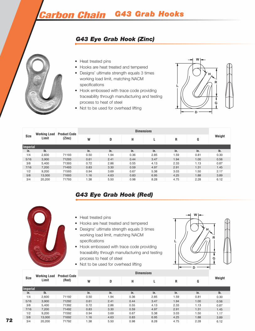
Carbon Chain G43 Grab HooksG43 Grab Hooks
72
G43 Eye Grab Hook (Red)
G43 Eye Grab Hook (Zinc)
• Heat treated pins• Hooks are heat treated and tempered• Designs’ ultimate strength equals 3 times
working load limit, matching NACMspecifications
• Hook embossed with trace code providingtraceability through manufacturing and testingprocess to heat of steel
• Not to be used for overhead lifting
• Heat treated pins• Hooks are heat treated and tempered• Designs’ ultimate strength equals 3 times
working load limit, matching NACMspecifications
• Hook embossed with trace code providingtraceability through manufacturing and testingprocess to heat of steel
• Not to be used for overhead lifting
H
L
W
R
D
G
H
L
W
R
D
G
W D H L R G
in. lb. in. in. in. in. in. in. lb.1/4 2,600 71193 0.50 1.94 0.36 2.85 1.59 0.81
5/16 3,900 71293 0.61 2.41 0.44 3.47 1.94 1.003/8 5,400 71393 0.72 2.86 0.55 4.13 2.33 1.137/16 7,200 71493 0.83 3.30 0.59 4.97 2.91 1.311/2 9,200 71593 0.94 3.69 0.67 5.38 3.03 1.505/8 13,000 71693 1.16 4.63 0.83 6.95 4.25 1.883/4 20,200 71793 1.38 5.50 0.98 8.28 4.75 2.28
Imperial
WeightDimensions
Size Working Load Limit
Product Code (Zinc)
0.30
0.560.871.452.173.896.12
W D H L R G
in. lb. in. in. in. in. in. in. lb.1/4 2,600 71192 0.50 1.94 0.36 2.85 1.59 0.81
5/16 3,900 71292 0.61 2.41 0.44 3.47 1.94 1.003/8 5,400 71392 0.72 2.86 0.55 4.13 2.33 1.137/16 7,200 71492 0.83 3.30 0.59 4.97 2.91 1.311/2 9,200 71592 0.94 3.69 0.67 5.38 3.03 1.505/8 13,000 71692 1.16 4.63 0.83 6.95 4.25 1.883/4 20,200 71792 1.38 5.50 0.98 8.28 4.75 2.28
Imperial
WeightDimensions
Size Working Load Limit
Product Code (Red)
0.30
0.560.871.451.173.896.12

G30 ChainG30 Chain
73
Car
bo
n C
hain
G30 Hanger Chain
G30 Chain
in. lb. lb. per ft.3/16 800 0.213 0.970 0.360 0.37 12.37
1/4 1,300 0.270 1.220 0.460 0.60 9.84
5/16 1,900 0.309 1.220 0.460 0.81 9.84
3/8 2,650 0.386 1.370 0.600 1.33 8.761/2 4,500 0.500 1.730 0.810 2.27 6.94
5/8 6,900 0.625 1.916 0.855 3.63 6.26
3/4 10,600 0.781 2.397 1.070 5.68 5.01
A B C
Imperial
App. No of Links
Chain Size
Working Load Limit
App. Weight
in. in. in.
B
C
A
• Meets ASTM & NACM standards• Available in a wide assortment of finishes including, Self Colored,
Burnished, Zinc Plated, Galvanized, Powder Coated• Permanent identification on chain• 100% proof tested• Available in drums, pails, multiple style of assemblies
Gr-30, commonly called Proof Coil, is manufactured to meet ASTM & NACM specifications. Typical usesinclude barrier chains, trailer safety chains, light construction, marine industry, etc. Gr-30 is available in a wideassortment of finishes and packaged configurations. "Gr-30 is not to be used for overhead lifting".
Chain Size Working Load Limit Product Code L Finish Weight
in. lb. ft. lb.1/4 1,300 601710 3 Self Colored 2.101/4 1,300 631001 3' 6 " Self Colored 2.40
1/4 1,300 601711 4 Self Colored 2.70
1/4 1,300 601712 5 Self Colored 3.00
1/4 1,300 601713 6 Self Colored 3.90
1/4 1,300 601714 7 Self Colored 4.50
1/4 1,300 601715 8 Self Colored 5.105/16 1,900 631012 6 Self Colored 5.60
Imperial
L
Chain Size
Full Drum Length Half
DrumLength Full
Drum Length Half Drum Length Pail Length Full
Drum Length Half Drum Length Pail Length
in. ft. ft. ft. ft. ft. ft. ft. ft.
1/4
671040 850 671094 500 671440 850 671494 500 671410 250 671340 850 671394 500 671310 250
5/16
671041 800 671091 400 671441 800 671491 400 671411 140 671341 800 671391 400 671311 140
3/8
671042 550 671092 275 671442 550 671492 275 671412 90 671342 550 671392 275 671312 90671043 400 671093 200 671443 400 671493 200 671413 60 671343 400 671393 200 671313 60
1/2
5/8
671065 350 671045 200 - - 671445 200 671415 40 671345 200 671395 100 671315 40
3/4
- - 671046 150 - - - - - - 671366 250 671346 150 - -671067 170 671047 100 - - - - - - 671367 170 671347 100 - -
Zinc Plated Finish Hot Dipped Galvanized FinishSelf Colored Finish
Imperial
3/16

Carbon Chain
G30 Eye Slip Hook
G30 Slip HooksG30 Slip Hooks
G30 Clevis Slip Hook
74
• Designed to be used with grade 30 chain• Heat treated pins• Hooks are heat treated and tempered• Hooks are embossed with chain grade, fraction
size and country of origin (USA)• Hooks embossed with a trace code• Ultimate strength equals 3 times the working
load limit, matching NACM specifications• Not to be used for overhead lifting
H
L
W
R
D
P
W D H L R P
in. lb. in. in. in. in. in. in. lb.1/4 1,300 66191 0.36 2.33 0.72 2.27 2.32 0.31
5/16 1,900 66291 0.42 2.72 0.77 4.13 2.56 0.383/8 2,650 66391 0.50 3.20 0.86 4.81 3.04 0.441/2 4,500 66591 0.61 4.16 1.12 6.31 4.15 0.55
Imperial
WeightDimensions
Size Working Load Limit
Product Code (Zinc)
0.35
0.631.022.27
H
L
W
G
D
R
• Designed to be used with grade 30 chain• Heat treated pins• Hooks are heat treated and tempered• Hooks are embossed with chain grade, fraction
size and country of origin (USA)• Hooks embossed with a trace code• Ultimate strength equals 3 times the working
load limit, matching NACM specifications• Not to be used for overhead lifting
W D H L R G
in. lb. in. in. in. in. in. in. lb.3/16-1/4 1,300 75191 0.53 2.47 0.81 3.69 2.61 0.81
5/16 1,900 75291 0.69 2.88 0.83 3.98 2.70 0.913/8 2,650 75391 0.75 3.25 0.92 4.56 3.17 1.137/16 3,700 75491 0.91 3.73 1.23 5.56 3.64 1.311/2 4,500 75591 1.03 4.25 1.30 6.13 4.20 1.505/8 6,900 75691 1.28 5.23 1.69 7.41 5.11 1.81
Imperial
WeightDimensions
Size Working Load Limit
Product Code (Zinc)
0.38
0.570.831.381.953.72

G30 Grab HooksG30 Grab Hooks
G30 Eye Grab Hooks
G30 Clevis Grab Hooks
75
Car
bo
n C
hain
• Designed to be used with grade 30 chain• Heat treated pins• Hooks are heat treated and tempered• Hooks are embossed with chain grade, fraction
size and country of origin (USA)• Hooks embossed with a trace code• Ultimate strength equals 3 times the working
load limit, matching NACM specifications• Not to be used for overhead lifting
H
L
W
R
D
P
W D H L R P
in. lb. in. in. in. in. in. in. lb.1/4 1,300 61191 0.36 2.05 0.36 3.00 1.57 0.31
5/16 1,900 61291 0.42 2.41 0.44 3.56 1.98 0.383/8 2,650 61391 0.50 2.94 0.52 4.20 2.23 0.441/2 4,500 61591 0.66 3.70 0.67 5.20 2.93 0.55
Imperial
WeightDimensions
Size Working Load Limit
Product Code (Zinc)
0.37
0.631.102.42
• Designed to be used with grade 30 chain• Heat treated pins• Hooks are heat treated and tempered• Hooks are embossed with chain grade, fraction
size and country of origin (USA)• Hooks embossed with a trace code• Ultimate strength equals 3 times the working
load limit, matching NACM specifications• Not to be used for overhead lifting
H
L
W
R
D
G
W D H L R G
in. lb. in. in. in. in. in. in. lb.3/16-1/4 1,300 71191 0.50 1.94 0.36 2.85 1.59 0.81
5/16 1,900 71291 0.61 2.41 0.44 3.47 1.94 1.003/8 2,650 71391 0.72 2.86 0.55 4.13 2.33 1.131/2 4,500 71591 0.94 3.69 0.67 5.38 3.03 1.50
Imperial
WeightDimensions
Size Working Load Limit
Product Code (Zinc)
0.30
0.500.872.17
For 7/16”, 5/8” or 3/4” size use grade 43 Eye Grab Hook

Carbon Chain Heavy Duty THeavy Duty Tiedownsiedowns
G80 & G100 Heavy Duty Tiedowns
76
Chain Size Chain Grade
Working Load Limit Product Code L Finish App. Weight
in. lb. ft. lb.3/8 80 7,100 607037CL20 20 Black 31
3/8 80 7,100 607037CL25 25 Black 38
1/2 80 12,000 607050CL15 15 Black 42
1/2 80 12,000 607050CL20 20 Black 55
3/8 100 8,800 607337CL20 20 Gray 31
3/8 100 8,800 607337CL25 25 Gray 38
Imperial
• Meets FMCSA, CVSA tiedown requirements• Made from high quality alloy steel• Permanent identification on chain and
attachments• Recommended chain for heavy equipment• Made to order assemblies available in 3
days or less
L
! !WARNINGDeath/injury can occur from improper use ormaintenance of tie-down equipment.
To avoid injury:• Inspect before use. Remove from service
if cracked, worn, or deformed.• Do not overload. Load binders develop
approximate working load with handeffort.
• Do not use handle extender on loadbinder(s).
• Do not use binder components foroverhead lifting.
Speci
alt
y C
hain
Speci
alt
y C
hain
G80 Winch Line / Tail Chain . . . . . . . . . . . . . . . . . . . .78Side Chain . . . . . . . . . . . . . . . . . . . . . . . . . . . . . . . . .78Claw Cross Chain . . . . . . . . . . . . . . . . . . . . . . . . . . . .78Cross Chain Hooks . . . . . . . . . . . . . . . . . . . . . . . . . . .79Machine Chain Straight . . . . . . . . . . . . . . . . . . . . . . .79Machine Chain Twisted Link . . . . . . . . . . . . . . . . . . .79Coil Chain Straight Link . . . . . . . . . . . . . . . . . . . . . . .80Coil Chain Twisted Link . . . . . . . . . . . . . . . . . . . . . . .80Passing Link . . . . . . . . . . . . . . . . . . . . . . . . . . . . . . . .80Double Loop Chain . . . . . . . . . . . . . . . . . . . . . . . . . . .81Single Loop Chain . . . . . . . . . . . . . . . . . . . . . . . . . . .81Special Well Chain . . . . . . . . . . . . . . . . . . . . . . . . . . .81Jack Chain . . . . . . . . . . . . . . . . . . . . . . . . . . . . . . . . .82Plumber Chain . . . . . . . . . . . . . . . . . . . . . . . . . . . . . .82Sash Chain . . . . . . . . . . . . . . . . . . . . . . . . . . . . . . . . .83Buoy Chain . . . . . . . . . . . . . . . . . . . . . . . . . . . . . . . . .83Long Wall Mining Chain . . . . . . . . . . . . . . . . . . . . . . .84Padless Shackle Connectors . . . . . . . . . . . . . . . . . . .85Special Chain Connector . . . . . . . . . . . . . . . . . . . . . .85Drive Sprockets . . . . . . . . . . . . . . . . . . . . . . . . . .86-87Grinding Mill Liner Bolt Specifications . . . . . . . . . . 88

Specialty Chain
Chain Size Working Load Limit Product Code L Finish Weight
in. lb. in. lb.5/8 18,100 695178 18 Black 8.16
3/4 28,300 695180 18 Black 13.64
7/8 34,200 695183 24 Black 19.44
1 47,700 695185 24 Black 24.46
Imperial
• Available in Grade 43 & Grade 80• Most comprehensive line in the market• Working Load Limits up to 47,700 lbs• Odd number of links to prevent twisting of chain during hook up• All assemblies 100% proof tested
Trade Size Product Code Polished A B C Links Weight
in. in. in. per ft. lb. / ft.6/0 214579 0.281 1.830 0.500 6.56 0.597/0 214581 0.312 2.070 0.500 5.80 0.728/0 214584 0.343 1.937 0.531 6.20 0.889/0 214585 0.375 2.260 0.610 5.31 1.0711/0 214588 0.437 2.330 0.656 5.15 1.49
Imperial
• Made from Mild Carbon Steel• Use to attach cross chain on the rim
of tires• Available in Zinc Plated upon request
B
C
A
L
Side Chain
Winch Line / Tail Chain Gr-80
78
Claw Cross Chain
• Made from tear drop shape steel for improved traction• Commercial grade chain for heavy duty trucks• Case hardened for longer wear• Components available to fit chain• Cut lengths available from
7 to 27 links
B
CA
Trade Size Product Code
Quantity Per Pack A B C Finish Weight
ft. in. in. in. lb. / ft.7/0 315931 100 0.312 1.093 0.467 Self Colored 1.008/0 315934 100 0.343 1.234 0.537 Self Colored 1.27
9/0 315937 100 0.375 1.266 0.671 Self Colored 1.60
Imperial
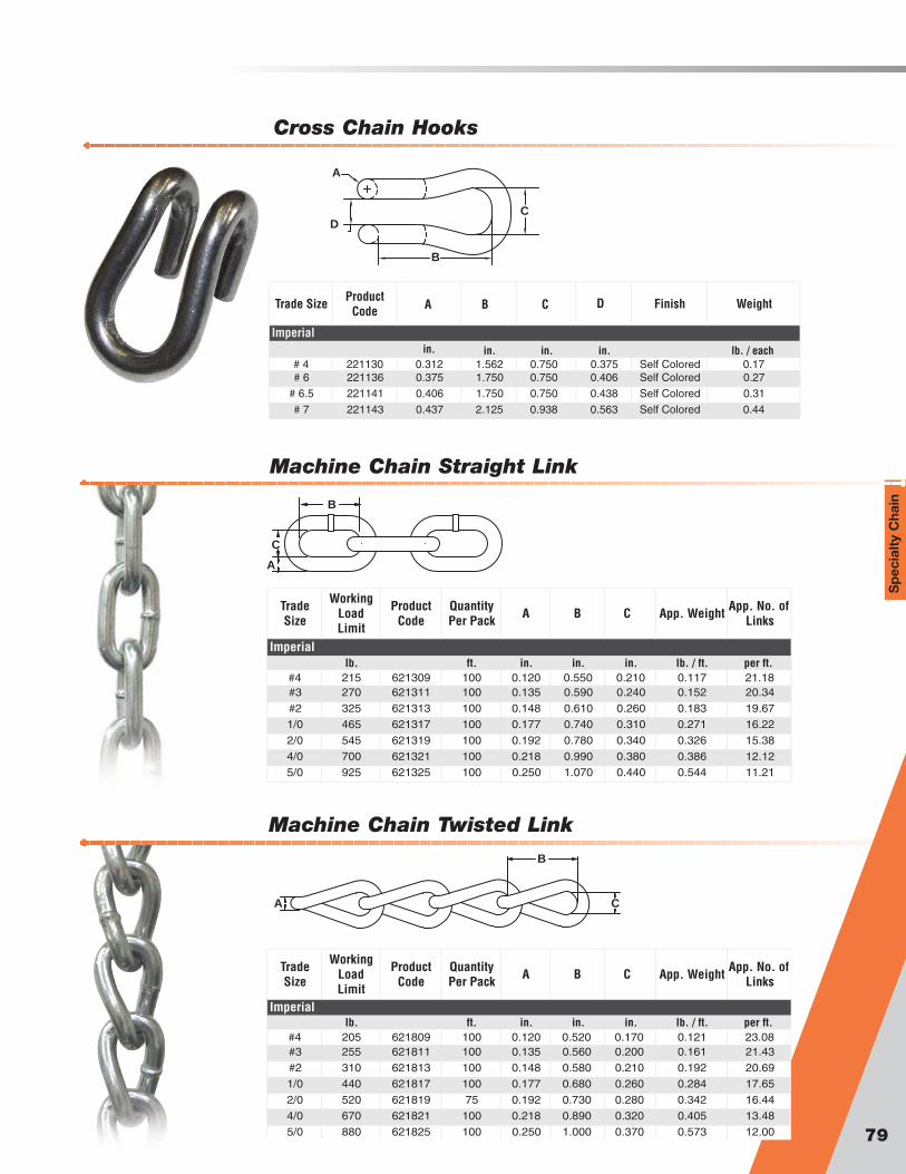
79
Sp
ecia
lty
Cha
in
Cross Chain Hooks
C
A
D
B
Trade Size
Working Load Limit
Product Code
Quantity Per Pack A B C App. Weight App. No. of
Links
lb. ft. in. in. in. lb. / ft. per ft. #4 215 621309 100 0.120 0.550 0.210 0.117 21.18#3 270 621311 100 0.135 0.590 0.240 0.152 20.34
#2 325 621313 100 0.148 0.610 0.260 0.183 19.67
1/0 465 621317 100 0.177 0.740 0.310 0.271 16.22
2/0 545 621319 100 0.192 0.780 0.340 0.326 15.38
4/0 700 621321 100 0.218 0.990 0.380 0.386 12.12
5/0 925 621325 100 0.250 1.070 0.440 0.544 11.21
Imperial
Machine Chain Twisted Link
Machine Chain Straight Link
B
C
A
B
CA
Trade Size
Working Load Limit
Product Code
Quantity Per Pack A B C App. Weight App. No. of
Links
lb. ft. in. in. in. lb. / ft. per ft. #4 205 621809 100 0.120 0.520 0.170 0.121 23.08#3 255 621811 100 0.135 0.560 0.200 0.161 21.43
#2 310 621813 100 0.148 0.580 0.210 0.192 20.69
1/0 440 621817 100 0.177 0.680 0.260 0.284 17.65
2/0 520 621819 75 0.192 0.730 0.280 0.342 16.44
4/0 670 621821 100 0.218 0.890 0.320 0.405 13.48
5/0 880 621825 100 0.250 1.000 0.370 0.573 12.00
Imperial
Trade Size Product Code A B C Finish Weight
in. in. in. lb. / each# 4 221130 0.312 1.562 0.750 0.375 Self Colored 0.17# 6 221136 0.375 1.750 0.750 0.406 Self Colored 0.27
# 6.5 221141 0.406 1.750 0.750 0.438 Self Colored 0.31
# 7 221143 0.437 2.125 0.938 0.563 Self Colored 0.44
Imperialin.
D

Specialty Chain Coil ChainCoil Chain
Trade Size
Working Load Limit
Product Code
Quantity Per Pack A B C App. Weight App. No. of
Links
lb. ft. in. in. in. lb. / ft. per ft. #4 205 620309 100 0.120 1.110 0.210 0.10 10.81#3 255 620311 100 0.135 1.170 0.240 0.13 10.26
#2 310 620313 75 0.148 1.180 0.260 0.15 10.17
1/0 440 620317 100 0.177 1.250 0.310 0.22 9.60
2/0 520 620319 100 0.192 1.260 0.340 0.27 9.52
4/0 670 620321 100 0.218 1.390 0.380 0.35 8.63
5/0 880 620325 100 0.250 1.520 0.440 0.46 7.89
Trade Size
Working Load Limit
Product Code
Quantity Per Pack A B C App. Weight App. No. of
Links
lb. ft. in. in. in. lb. / ft. per ft. #4 195 620809 100 0.120 1.090 0.180 0.104 11.01#3 240 620811 100 0.135 1.140 0.210 0.139 10.53
#2 295 620813 100 0.148 1.150 0.220 0.156 10.43
1/0 415 - 100 0.177 1.220 0.270 0.231 9.84
2/0 495 620819 100 0.192 1.240 0.290 0.282 9.68
4/0 635 620821 100 0.218 1.340 0.330 0.370 8.96
5/0 835 620825 100 0.250 1.470 0.380 0.485 8.16
Trade Size
Working Load Limit
Product Code
Quantity Per Pack A B C App. Weight App. No. of
Links
lb. ft. in. in. in. lb. / ft. per ft. 2/0 450 623459 100 0.192 0.875 0.470 0.33 13.713/0 540 623460 100 0.207 0.875 0.470 0.38 13.71
4/0 600 623461 100 0.218 0.875 0.470 0.43 13.71
Imperial
Imperial
Imperial
Coil Chain Twist Link
Coil Chain Straight Link
Passing Link
B
C
A
80
B
CA
B
C
A

WWeldless Chaineldless Chain
Single Loop Chain
Double Loop Chain
81
Sp
ecia
lty
Cha
inSpecial Well Chain
B
A
B
A
B
A
Double Loop typical usesinclude; suspension oflighting, animal leashes,swings & hammocks
•Meets or exceeds ASTM & NACM standardswhere applicable
•Available in various finishes•Sold by carton, reel or pails•Custom cuts for OEM applications are available
• Meets or exceeds ASTM & NACM standardswhere applicable
• Available in various finishes• Sold by carton, reel or pails• Custom cuts for OEM applications are available
• Meets or exceeds ASTM & NACM standardswhere applicable
• Available in various finishes• Sold by carton, reel or pails• Custom cuts for OEM applications are available
Single Loop typical usesinclude; overhead doorapplications, ventilators,operating value wheels,sprocket wheels requiringmore strength than doubleloop chain
Special well chain typicallyused in cisterns
Trade Size
Working Load Limit
Product Code Self Colored
Product Code Zinc
Plated
Quantity Per
CartonA B App. Weight App. No.
of Links
lb. ft. in. in. lb. / ft. per ft. #5 55 680150 680450 100 0.062 0.920 0.04 13#4 70 680151 680451 100 0.072 1.000 0.05 12
#3 90 680152 680452 100 0.080 1.100 0.06 11
#2 115 680153 680453 100 0.091 1.330 0.08 9
#1 155 680154 680454 100 0.105 1.540 0.10 8
1/0 200 680155 680455 100 0.120 1.780 0.13 7
2/0 255 680156 680456 100 0.135 1.820 0.17 7
3/0 305 680157 680457 100 0.148 2.170 0.20 5.5
4/0 365 680158 680458 100 0.162 2.190 0.25 5.5
Trade Size
Working Load Limit
Product Code Self Colored
Product Code Zinc
Plated
Quantity Per
CartonA B App. Weight App. No.
of Links
lb. ft. in. in. lb. / ft. per ft. 1/0 265 681151 681451 100 0.120 1.290 0.17 9.3
2/0 340 681152 681452 100 0.135 1.480 0.22 8.1
3/0 405 681153 681453 75 0.148 1.630 0.26 7.4
4/0 485 681154 681454 100 0.162 1.800 0.31 6.7
Trade Size
Working Load Limit
Product Code
Quantity Per
CartonA B App.
WeightApp. No. of
Links
lb. ft. in. in. lb. / ft. per ft. 2/0 255 679456 100 0.135 2.500 0.15 4.8
Imperial
Imperial
Imperial
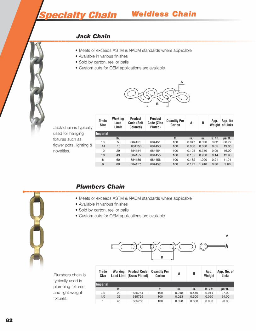
Specialty Chain
Plumbers Chain
WWeldless Chaineldless Chain
Jack Chain
82
Trade Size
Working Load Limit
Product Code (Self Colored)
Product Code (Zinc
Plated)
Quantity Per Carton A B App.
WeightApp. No of Links
lb. ft. in. in. lb. / ft. per ft. 18 5 684151 684451 100 0.047 0.390 0.02 30.7714 16 684153 684453 100 0.080 0.630 0.05 19.05
12 29 684154 684454 100 0.105 0.750 0.09 16.00
10 43 684155 684455 100 0.135 0.930 0.14 12.90
8 60 684156 684456 100 0.162 1.090 0.21 11.01
6 88 684157 684457 100 0.192 1.240 0.30 9.68
Imperial
B
A
Trade Size
Working Load Limit
Product Code (Brass Plated)
Quantity Per Carton A B App.
WeightApp. No. of
Links
lb. ft. in. in. lb. / ft. per ft. 2/0 23 685754 100 0.018 0.440 0.014 27.001/0 35 685755 100 0.023 0.500 0.020 24.00
1 45 685756 100 0.028 0.600 0.033 20.00
Imperial
Jack chain is typicallyused for hangingfixtures such asflower pots, lighting &novelties.
Plumbers chain istypically used inplumbing fixturesand light weightfixtures.
• Meets or exceeds ASTM & NACM standards where applicable• Available in various finishes• Sold by carton, reel or pails• Custom cuts for OEM applications are available
• Meets or exceeds ASTM & NACM standards where applicable• Available in various finishes• Sold by carton, reel or pails• Custom cuts for OEM applications are available
B
A

Specialty ChainSpecialty Chain
83
Sash Chain
Trade Size
WorkingLoad Limit
(Self Colored)
(Zinc Plated)
(Copper Dipped)
QuantityPer
CartonA B App.
Weight
App. No. of Links
lb. ft. in. in. lb. / ft. per ft. 8 75 683151 683451 683551 100 0.035 0.550 3.90 21.8225 94 683152 683452 683552 100 0.042 0.550 4.90 21.82
30 81 683153 683453 683553 100 0.028 0.560 5.50 21.43
35 106 683154 683454 683554 100 0.035 0.560 5.90 21.43
40 131 683156 683456 683556 100 0.042 0.560 8.00 21.43
45 175 683157 683457 683557 100 0.050 0.560 9.50 21.43
50 225 683158 683458 683558 100 0.062 0.590 12.00 20.34
Imperial
Product Code
B A
Typically uses forsash chain arepulley applicationsin windows andwindow sashes.
• Meets or exceeds ASTM & NACM standards where applicable• Available in various finishes• Sold by carton, reel or pails• Custom cuts for OEM applications are available
Buoy Chain
ChainSize
Working Load Limit
Product Code L A B C D E F Finish Weight
in. lb. ft. in. in. in. in. in. in. lb. / ft. 1/2 15,000 6510049 90 0.500 3.00 1.875 0.750 4.50 2.688 Self Colored 2.15
1/2 15,000 6510048 45 0.500 3.00 1.875 0.750 4.50 2.688 Self Colored 2.15
3/4 32,000 6510050 90 0.750 4.50 2.688 0.875 5.25 3.125 Self Colored 4.80
3/4 32,000 6510051 45 0.750 4.50 2.688 0.875 5.25 3.125 Self Colored 4.80
1 58,000 4340890 90 1.000 6.00 3.583 1.000 4.08 1.563 Self Colored 8.60
1 58,000 4340890G 90 1.000 6.00 3.583 1.000 4.08 1.563 Hot dipped Galvanized 9.60
1-1/8 77,000 4340990 90 1.125 6.75 4.000 1.125 4.59 1.750 Self Colored 10.80
1-1/4 91,000 4341090 90 1.250 7.50 4.438 1.250 5.10 1.938 Self Colored 13.50
Imperial
Chain Dimensions Endlink Dimensions
L
B
C
A
E
F
D
Sp
ecia
lty
Cha
in
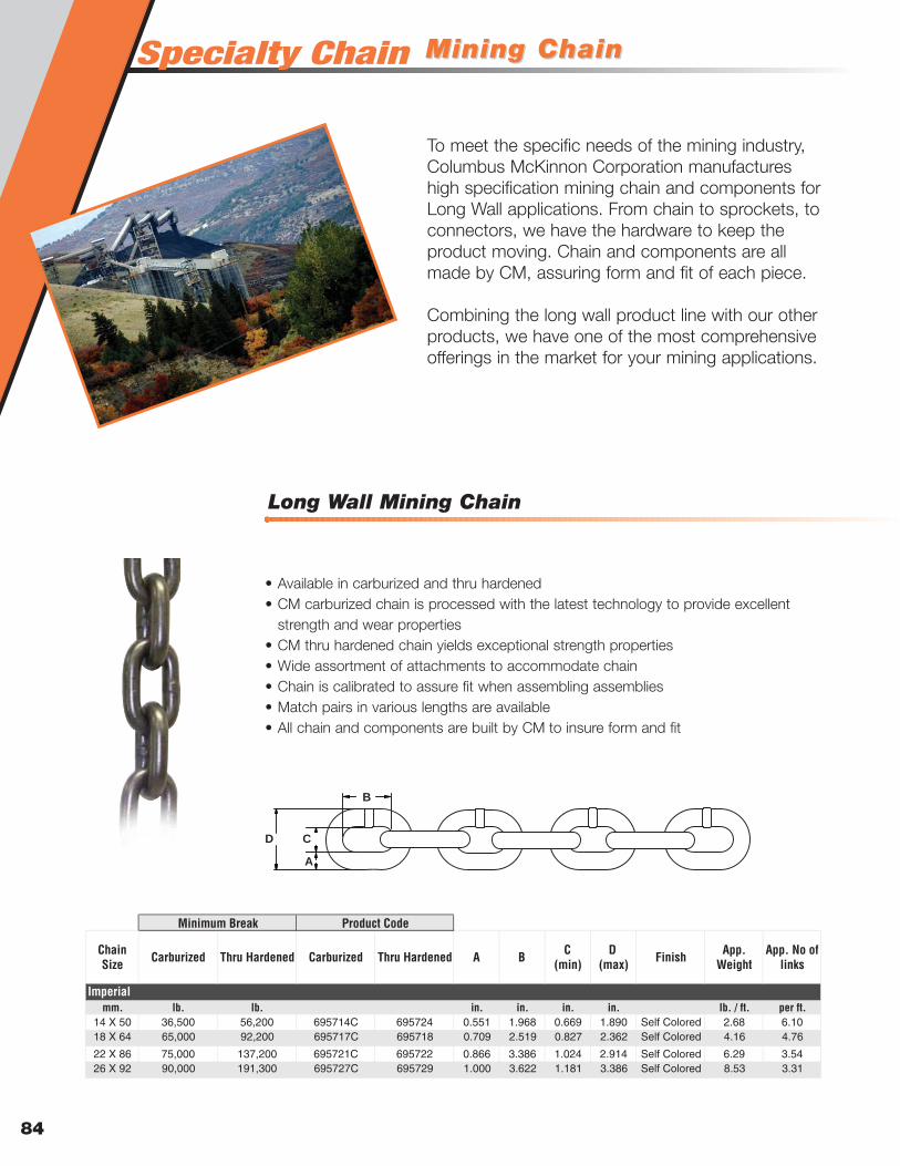
Specialty Chain
Long Wall Mining Chain
Mining ChainMining Chain
84
Chain Size Carburized Thru Hardened Carburized Thru Hardened A B C
(min)D
(max) Finish App. Weight
App. No of links
mm. lb. lb. in. in. in. in. lb. / ft. per ft.14 X 50 36,500 56,200 695714C 695724 0.551 1.968 0.669 1.890 Self Colored 2.68 6.1018 X 64 65,000 92,200 695717C 695718 0.709 2.519 0.827 2.362 Self Colored 4.16 4.76
22 X 86 75,000 137,200 695721C 695722 0.866 3.386 1.024 2.914 Self Colored 6.29 3.5426 X 92 90,000 191,300 695727C 695729 1.000 3.622 1.181 3.386 Self Colored 8.53 3.31
Imperial
Minimum Break Product Code
B
C
A
D
• Available in carburized and thru hardened• CM carburized chain is processed with the latest technology to provide excellent
strength and wear properties• CM thru hardened chain yields exceptional strength properties• Wide assortment of attachments to accommodate chain• Chain is calibrated to assure fit when assembling assemblies• Match pairs in various lengths are available• All chain and components are built by CM to insure form and fit
To meet the specific needs of the mining industry,Columbus McKinnon Corporation manufactureshigh specification mining chain and components forLong Wall applications. From chain to sprockets, toconnectors, we have the hardware to keep theproduct moving. Chain and components are allmade by CM, assuring form and fit of each piece.
Combining the long wall product line with our otherproducts, we have one of the most comprehensiveofferings in the market for your mining applications.

Mining ChainMining Chain
Special Chain Connector
Padless Shackle Connectors
85
Sp
ecia
lty
Cha
in
Chain Size Bolt Size Product
Code A B C D E F G Weight
mm. in. in. in. in. in. lb.
14 X 50 5/8-11 UNC X 2-1/2" Gr- M14JL 0.560 0.690 1.160 1.970 1.890 0.690 - 0.5018 X 64 5/8-11 UNC X 3" Gr-8 M18JL 0.720 0.690 1.260 2.520 2.000 0.780 - 1.31
22 X 86 7/8-9 UNC X 4" Gr-8 M22JL 0.880 0.970 2.000 3.390 2.940 1.140 - 0.5026 x 92 1-8 UNC X 4-1/2" Gr-8 M26JL 1.060 1.060 2.250 3.620 3.500 1.120 - 1.31
14 X 50 5/8 -11 UNC
X
2-1/2
Gr-8 M14JL4 0.560 0.690 1.160 1.970 1.890 0.690 1.380 1.13
18 X 64 5/8-11 UNC X 3" Gr-8 M18JL4 0.720 0.640 1.260 2.520 2.000 0.780 1.750 2.13
22 X 86 5/8-11 UNC
X
3-1/2
Gr-8 M22JL4 0.880 0.690 2.000 3.390 2.940 1.140 1.560 4.25
26 x 92 7/8-9 UNC X 4" Gr-8 M26JL4 1.060 0.940 2.250 3.620 3.750 1.120 2.380 7.63
Imperial
2 Bolt
1 Boltin. in.
C
A
B E
F
D
C
A
B E
D
F
G
D
B
A
C
G
EF
Chain Size
Product Code A B C D E F G Bolt Size
(Gr-8) Weight
mm. in. in. in. in. in. in. in. in. lb.14 X 50 M14HC 0.560 0.690 1.160 1.970 1.890 0.690 1.380 5/8-11 UNC X 2-1/2 1.1318 X 64 M18HC4 0.720 0.640 1.260 2.520 2.000 0.780 1.750 5/8-11 UNC X 3 2.13
Imperial
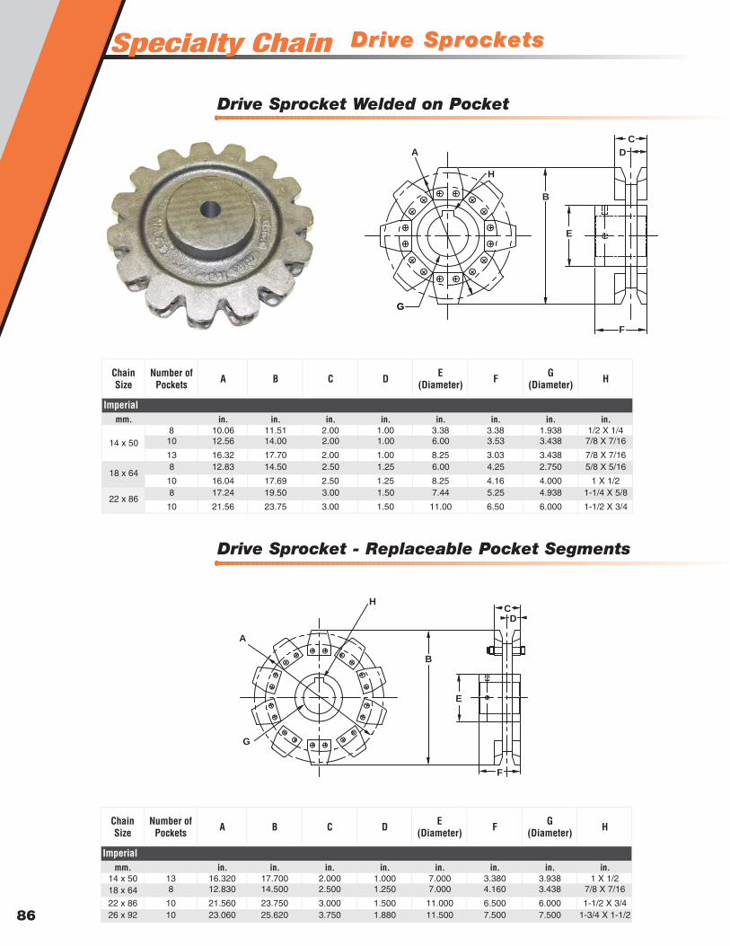
Specialty Chain
Drive Sprocket - Replaceable Pocket Segments
Drive SprDrive Sprocketsockets
Drive Sprocket Welded on Pocket
86
Chain Size
Number of Pockets A B C D E
(Diameter) F G (Diameter) H
mm. in. in. in. in. in. in. in. in.8 10.06 11.51 2.00 1.00 3.38 3.38 1.938 1/2 X 1/410 12.56 14.00 2.00 1.00 6.00 3.53 3.438 7/8 X 7/16
13 16.32 17.70 2.00 1.00 8.25 3.03 3.438 7/8 X 7/168 12.83 14.50 2.50 1.25 6.00 4.25 2.750 5/8 X 5/16
10 16.04 17.69 2.50 1.25 8.25 4.16 4.000 1 X 1/28 17.24 19.50 3.00 1.50 7.44 5.25 4.938 1-1/4 X 5/8
10 21.56 23.75 3.00 1.50 11.00 6.50 6.000 1-1/2 X 3/4
Imperial
14 x 50
18 x 64
22 x 86
Chain Size
Number of Pockets A B C D E
(Diameter) F G (Diameter) H
mm. in. in. in. in. in. in. in. in.14 x 50 13 16.320 17.700 2.000 1.000 7.000 3.380 3.938 1 X 1/218 x 64 8 12.830 14.500 2.500 1.250 7.000 4.160 3.438 7/8 X 7/16
22 x 86 10 21.560 23.750 3.000 1.500 11.000 6.500 6.000 1-1/2 X 3/426 x 92 10 23.060 25.620 3.750 1.880 11.500 7.500 7.500 1-3/4 X 1-1/2
Imperial
A
G
H
B
C
D
E
F
G
A
C
B
D
E
F
G
H
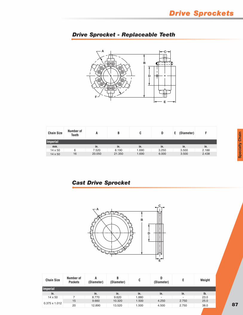
Drive SprDrive Sprocketsockets
Cast Drive Sprocket
Drive Sprocket - Replaceable Teeth
87
Sp
ecia
lty
Cha
inChain Size Number of Teeth A B C D E (Diameter) F
mm. in. in. in. in. in. in.14 x 50 6 7.520 8.190 1.690 3.250 3.500 2.18814 x 50 16 20.050 21.350 1.690 6.000 3.500 2.438
Imperial
Chain Size Number of Pockets
A (Diameter)
B (Diameter) C D
(Diameter) E Weight
in. in. in. in. in. in. lb.14 x 50 7 8.770 9.620 1.880 - - 23.0
15 9.660 10.320 1.500 4.250 2.750 25.0
20 12.890 13.520 1.500 4.500 2.750 38.0
Imperial
0.375 x 1.012
A C
B
D
E
F
AC
B
D
E
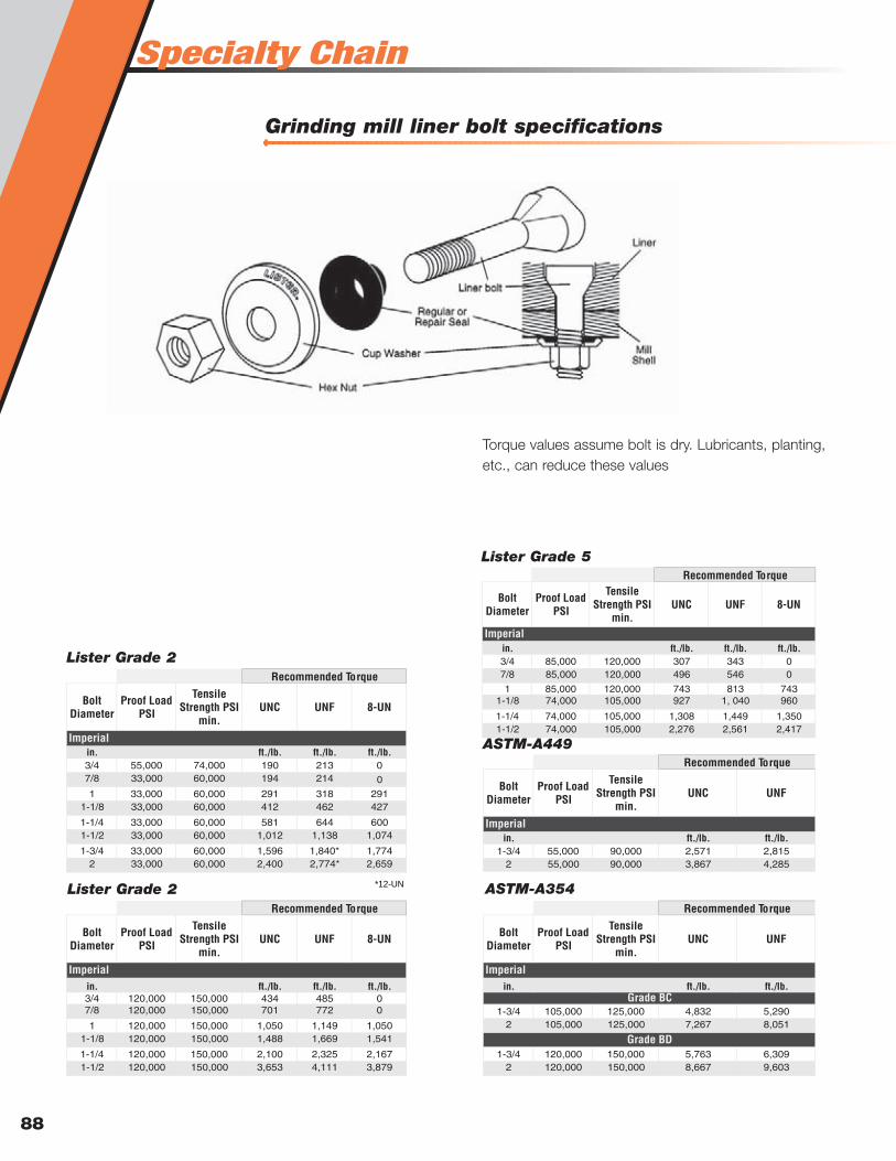
Specialty Chain
88
Bolt Diameter
Proof Load PSI
Tensile Strength PSI
min.UNC UNF 8-UN
Bolt Diameter
Proof Load PSI
Tensile Strength PSI
min.UNC UNF
in. ft./lb. ft./lb. ft./lb.
in. ft./lb. ft./lb.
3/4 55,000 74,000 190 213 0
1-3/4 55,000 90,000 2,571 2,815
7/8 33,000 60,000 194 214
2 55,000 90,000 3,867 4,285
1 33,000 60,000 291 318 2911-1/8 33,000 60,000 412 462 427
1-1/4 33,000 60,000 581 644 6001-1/2 33,000 60,000 1,012 1,138 1,074
1-3/4 33,000 60,000 1,596 1,840* 1,7742 33,000 60,000 2,400 2,774* 2,659
Bolt Diameter
Proof Load PSI
Tensile Strength PSI
min.UNC UNF 8-UN Bolt
DiameterProof Load
PSI
Tensile Strength PSI
min.UNC UNF
in. ft./lb. ft./lb. ft./lb. in. ft./lb. ft./lb.3/4 120,000 150,000 434 485 07/8 120,000 150,000 701 772 0 1-3/4 105,000 125,000 4,832 5,290
1 120,000 150,000 1,050 1,149 1,050 2 105,000 125,000 7,267 8,051
1-1/8 120,000 150,000 1,488 1,669 1,541
1-1/4 120,000 150,000 2,100 2,325 2,167 1-3/4 120,000 150,000 5,763 6,3091-1/2 120,000 150,000 3,653 4,111 3,879 2 120,000 150,000 8,667 9,603
Bolt Diameter
Proof Load PSI
Tensile Strength PSI
min.UNC UNF 8-UN
in. ft./lb. ft./lb. ft./lb.3/4 85,000 120,000 307 343 07/8 85,000 120,000 496 546 0
1 85,000 120,000 743 813 7431-1/8 74,000 105,000 927 1, 040 960
1-1/4 74,000 105,000 1,308 1,449 1,3501-1/2 74,000 105,000 2,276 2,561 2,417
Imperial
Recommended Torque
Recommended Torque
Imperial
Grade BC
Grade BD
Imperial
Recommended Torque
Imperial
Imperial
Recommended Torque
Recommended Torque
0
Grinding mill liner bolt specifications
Lister Grade 2
Lister Grade 2
Lister Grade 5
ASTM-A449
ASTM-A354
Torque values assume bolt is dry. Lubricants, planting,etc., can reduce these values
*12-UN

Wir
e R
ope a
ttach
ments
Wir
e R
ope a
ttach
ments
Swage Socket (open) . . . . . . . . . . . . . . . . . . . . . . . . .90Swage Button . . . . . . . . . . . . . . . . . . . . . . . . . . . . . . .91Swage Socket (closed) . . . . . . . . . . . . . . . . . . . . . . .91Swaging Sleeve for Flemish Eye . . . . . . . . . . . . . . . .92Mid Grip Clips . . . . . . . . . . . . . . . . . . . . . . . . . . . . . .93Wire Rope Clips . . . . . . . . . . . . . . . . . . . . . . . . . . . . .94Piggy Back Wedge Socket Clips . . . . . . . . . . . . . . . .95Thimbles . . . . . . . . . . . . . . . . . . . . . . . . . . . . . . . . . . .96
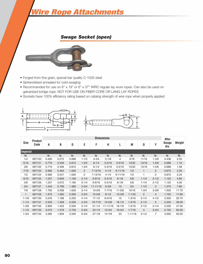
Wire Rope Attachments
90
Swage Socket (open)
A B D E F H L M O Y
in. in. in. in. in. in. in. in. in. in. in. in. lb.1/4 697120 0.495 0.272 0.688 1-1/2 4-3/4 2-1/8 4 5/16 11/16 1-3/8 0.438 0.55
5/16 697121 0.770 0.339 0.812 1-3/4 6-1/4 3-3/16 5-5/16 13/32 13/16 1-5/8 0.688 1.10
3/8 697122 0.770 0.406 0.812 1-3/4 6-1/4 3-3/16 5-5/16 13/32 13/16 1-5/8 0.688 1.08
7/16 697123 0.982 0.484 1.000 2 7-13/16 4-1/4 6-11/16 1/2 1 2 0.875 2.30
1/2 697124 0.982 0.547 1.000 2 7-13/16 4-1/4 6-11/16 1/2 1 2 0.875 2.25
9/16 697125 1.257 0.609 1.190 2-1/4 9-9/16 5-5/16 8-1/8 5/8 1-1/4 2-1/2 1.125 4.60
5/8 697126 1.257 0.672 1.190 2-1/4 9-9/16 5-5/16 8-1/8 5/8 1-1/4 2-1/2 1.125 4.50
3/4 697127 1.545 0.796 1.380 2-3/4 11-11/16 6-3/8 10 3/4 1-1/2 3 1.375 7.80
7/8 697128 1.700 0.938 1.630 3-1/4 13-5/8 7-7/16 11-5/8 15/16 1-3/4 3-3/8 1.500 11.70
1 697129 1.975 1.062 2.000 3-3/4 15-5/8 8-1/2 13-3/8 1-1/32 2 4 1.750 17.80
1-1/8 697130 2.245 1.188 2.250 4-1/4 17-1/2 9-9/16 15 1-3/16 2-1/4 4-1/2 2.000 29.70
1-1/4 697131 2.525 1.328 2.500 4-3/4 19-7/16 10-5/8 16-1/2 1-3/16 2-1/2 5 2.250 36.00
1-3/8 697132 2.800 1.453 2.500 5-1/4 21-1/4 11-11/16 18-1/8 1-5/16 2-1/2 5-1/4 2.500 47.00
1-1/2 697133 3.075 1.578 2.750 5-3/4 23-1/4 12-3/4 19-3/4 1-7/16 3 5-3/4 2.750 65.00
1-3/4 697134 3.385 1.859 3.500 6-3/4 27-1/8 14-7/8 23 1-11/16 3-1/2 7 3.000 93.00
Product Code
Imperial
Size WeightAfter
Swage dia.
Dimensions
• Forged from fine grain, special bar quality C-1035 steel• Spheroidized annealed for cold swaging• Recommended for use on 6” x 19” or 6” x 37” IWRC regular lay wore ropes. Can also be used on
galvanized bridge rope. NOT FOR USE ON FIBER CORE OR LANG LAY ROPES• Sockets have 100% efficiency rating based on catalog strength of wire rope when properly applied
B
A
H
L
D
Y
F
O
M
E

WWirire Rope Attachmentse Rope Attachments
91
WR
Att
achm
ents
Swage Buttons
Swage Socket (Closed)
Wi P
in. in. in. lb.1/8 697101 0.375 0.625 0.025
3/16 697102 0.500 0.875 0.050
1/4 697103 0.563 1.188 0.068
5/16 697104 0.750 1.375 0.156
3/8 697105 0.750 1.750 0.188
7/16 697106 1.000 2.000 0.393
1/2 697107 1.125 2.188 0.544
9/16 697108 1.250 2.438 0.737
5/8 697109 1.375 2.875 1.062
3/4 697110 1.500 3.250 1.356
7/8 697111 1.750 3.875 2.194
1 697112 2.000 4.375 3.15
1-1/8 697113 2.250 4.813 4.575
1-1/4 697114 2.500 5.438 7.000
1-3/8 697115 2.750 6.000 9.150
1-1/2 697116 3.000 6.500 12.025
Imperial
Rope Diameter Product Code Weight
Dimensions
P
Wi
• Forged from fine grain, special bar quality C-1035 steel• Spheroidized annealed for cold swaging• Recommended for use on 6” x 19” or 6” x 37” IWRC regular lay
wore ropes. Can also be used on galvanized bridge rope. NOTFOR USE ON FIBER CORE OR LANG LAY ROPES
• Sockets have 100% efficiency rating based on catalog strengthof wire rope when properly applied
A B C D E H K L
in. in. in. in. in. in. in. in. in. in. lb.1/4 697151 0.495 0.272 1-7/16 0.750 1/2 2-1/8 4-3/8 3-1/2 0.438 0.34
5/16 697152 0.770 0.339 1-11/16 0.875 11/16 3-3/16 5-1/2 4-1/2 0.688 0.79
3/8 697153 0.770 0.406 1-11/16 0.875 11/16 3-3/16 5-1/2 4-1/2 0.688 0.78
7/16 697154 0.982 0.484 2 1.063 7/8 4-1/4 6-15/16 5-3/4 0.875 1.45
1/2 697155 0.982 0.547 2 1.063 7/8 4-1/4 6-15/16 5-3/4 0.875 1.38
9/16 697156 1.257 0.609 2-1/2 1.250 1-1/8 5-5/16 8-3/4 7-1/4 1.125 2.78
5/8 697157 1.257 0.672 2-1/2 1.250 1-1/8 5-5/16 8-3/4 7-1/4 1.125 2.75
3/4 697158 1.545 0.796 3 1.438 1-5/16 6-3/8 10-3/8 8-5/8 1.375 5.00
7/8 697159 1.700 0.938 3-1/2 1.688 1-1/2 7-7/16 12-1/8 10-1/8 1.500 7.50
1 697160 1.975 1.062 4 2.063 1-3/4 8-1/2 13-3/4 11-1/2 1.750 11.20
1-1/8 697161 2.245 1.188 4-1/2 2.313 2 9-9/16 15-1/4 12-3/4 2.000 15.80
1-1/4 697162 2.525 1.328 5 2.563 2-1/4 10-5/8 17-1/4 14-3/8 2.250 23.00
1-3/8 697163 2.800 1.453 5-1/4 2.563 2-1/4 11-11/16 18-7/8 15-3/4 2.500 31.00
1-1/2 697164 3.075 1.578 5-1/2 2.813 2-1/2 12-3/4 20-3/8 17 2.750 39.00
1-3/4 697165 3.385 1.859 6-3/4 3.563 3 14-7/8 24 20 3.000 52.00
Product Code
Imperial
Size WeightAfter Swage dia.
Dimensions
• Fittings machined from specially selected andprocessed low carbon steel
• Buttons have 98% efficiency rating based on catalogstrength of wire rope when properly applied
B A
H
K
E
L
D
C
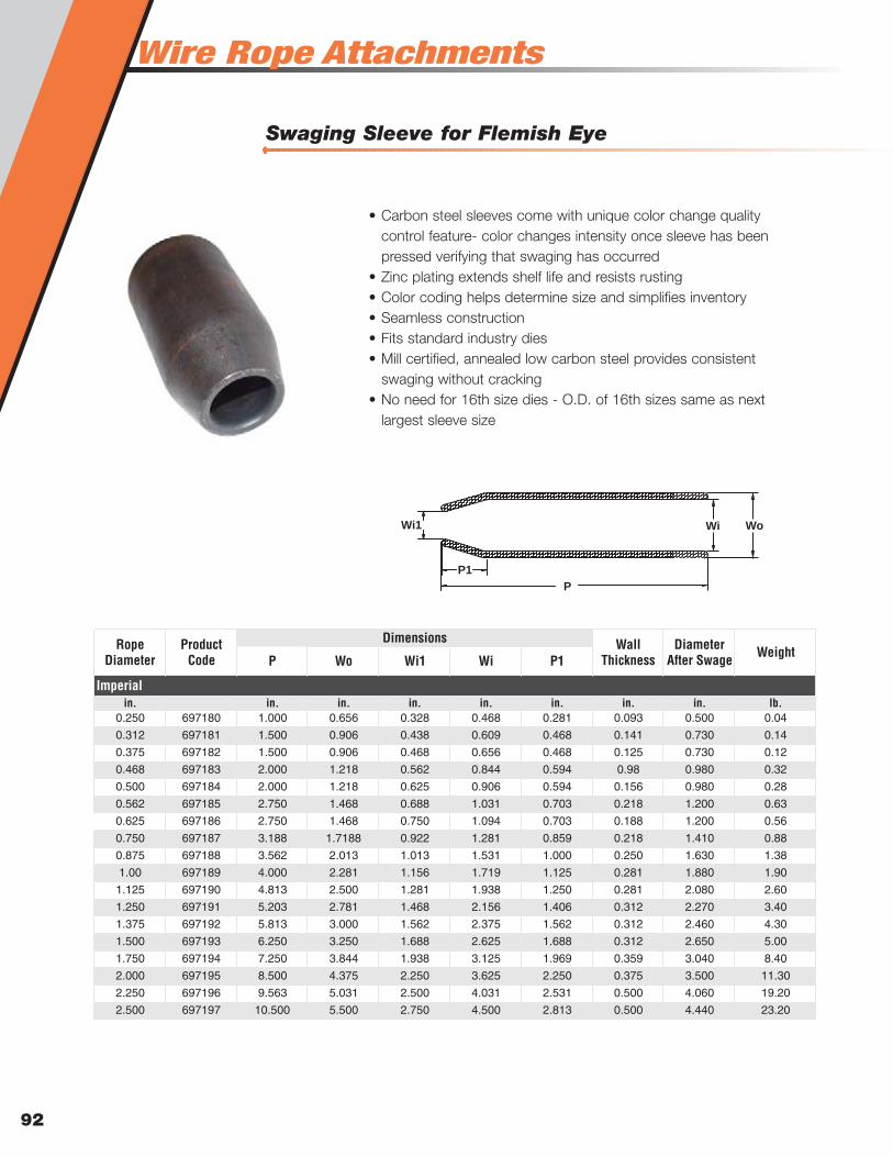
Wire Rope Attachments
92
Swaging Sleeve for Flemish Eye
P Wo Wi1 Wi P1
in. in. in. in. in. in. in. in. lb.0.250 697180 1.000 0.656 0.328 0.468 0.281 0.093 0.500 0.04
0.312 697181 1.500 0.906 0.438 0.609 0.468 0.141 0.730 0.14
0.375 697182 1.500 0.906 0.468 0.656 0.468 0.125 0.730 0.12
0.468 697183 2.000 1.218 0.562 0.844 0.594 0.98 0.980 0.32
0.500 697184 2.000 1.218 0.625 0.906 0.594 0.156 0.980 0.28
0.562 697185 2.750 1.468 0.688 1.031 0.703 0.218 1.200 0.63
0.625 697186 2.750 1.468 0.750 1.094 0.703 0.188 1.200 0.56
0.750 697187 3.188 1.7188 0.922 1.281 0.859 0.218 1.410 0.88
0.875 697188 3.562 2.013 1.013 1.531 1.000 0.250 1.630 1.38
1.00 697189 4.000 2.281 1.156 1.719 1.125 0.281 1.880 1.90
1.125 697190 4.813 2.500 1.281 1.938 1.250 0.281 2.080 2.60
1.250 697191 5.203 2.781 1.468 2.156 1.406 0.312 2.270 3.40
1.375 697192 5.813 3.000 1.562 2.375 1.562 0.312 2.460 4.30
1.500 697193 6.250 3.250 1.688 2.625 1.688 0.312 2.650 5.00
1.750 697194 7.250 3.844 1.938 3.125 1.969 0.359 3.040 8.40
2.000 697195 8.500 4.375 2.250 3.625 2.250 0.375 3.500 11.30
2.250 697196 9.563 5.031 2.500 4.031 2.531 0.500 4.060 19.20
2.500 697197 10.500 5.500 2.750 4.500 2.813 0.500 4.440 23.20
Imperial
Rope Diameter
Product Code Weight
Dimensions Wall Thickness
Diameter After Swage
P
P1
Wi1 Wi Wo
• Carbon steel sleeves come with unique color change qualitycontrol feature- color changes intensity once sleeve has beenpressed verifying that swaging has occurred
• Zinc plating extends shelf life and resists rusting• Color coding helps determine size and simplifies inventory• Seamless construction• Fits standard industry dies• Mill certified, annealed low carbon steel provides consistent
swaging without cracking• No need for 16th size dies - O.D. of 16th sizes same as next
largest sleeve size
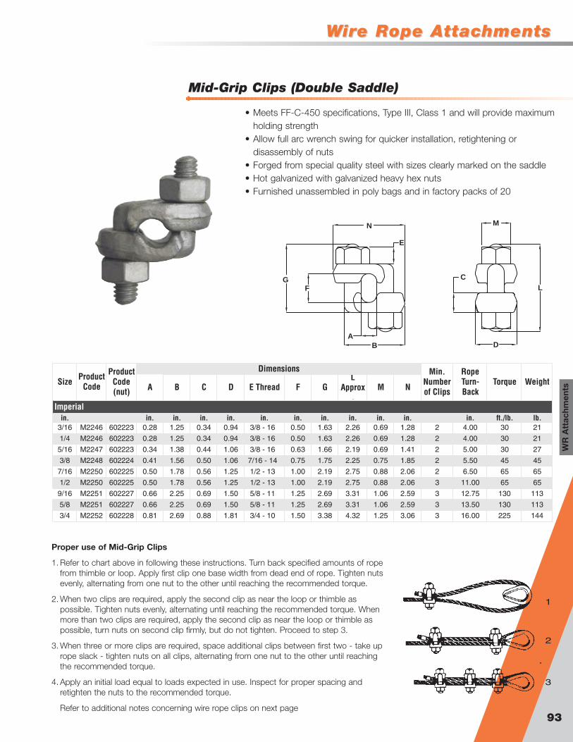
WWirire Rope Attachmentse Rope Attachments
93
WR
Att
achm
ents
Mid-Grip Clips (Double Saddle)
B
C
D
L
MN
E
A
FG
• Meets FF-C-450 specifications, Type III, Class 1 and will provide maximumholding strength
• Allow full arc wrench swing for quicker installation, retightening ordisassembly of nuts
• Forged from special quality steel with sizes clearly marked on the saddle• Hot galvanized with galvanized heavy hex nuts• Furnished unassembled in poly bags and in factory packs of 20
A B C D E Thread F GL
Approx.
M N
in. in. in. in. in. in. in. in. in. in. in. in. ft./lb. lb.3/16 M2246 602223 0.28 1.25 0.34 0.94 3/8 - 16 0.50 1.63 2.26 0.69 1.28 2 4.00 30 21
1/4 M2246 602223 0.28 1.25 0.34 0.94 3/8 - 16 0.50 1.63 2.26 0.69 1.28 2 4.00 30 21
5/16 M2247 602223 0.34 1.38 0.44 1.06 3/8 - 16 0.63 1.66 2.19 0.69 1.41 2 5.00 30 27
3/8 M2248 602224 0.41 1.56 0.50 1.06 7/16 - 14 0.75 1.75 2.25 0.75 1.85 2 5.50 45 45
7/16 M2250 602225 0.50 1.78 0.56 1.25 1/2 - 13 1.00 2.19 2.75 0.88 2.06 2 6.50 65 65
1/2 M2250 602225 0.50 1.78 0.56 1.25 1/2 - 13 1.00 2.19 2.75 0.88 2.06 3 11.00 65 65
9/16 M2251 602227 0.66 2.25 0.69 1.50 5/8 - 11 1.25 2.69 3.31 1.06 2.59 3 12.75 130 113
5/8 M2251 602227 0.66 2.25 0.69 1.50 5/8 - 11 1.25 2.69 3.31 1.06 2.59 3 13.50 130 113
3/4 M2252 602228 0.81 2.69 0.88 1.81 3/4 - 10 1.50 3.38 4.32 1.25 3.06 3 16.00 225 144
Product Code
Dimensions
Imperial
SizeProduct
Code (nut)
WeightMin.
Number of Clips
Rope Turn-Back
Torque
Proper use of Mid-Grip Clips
1. Refer to chart above in following these instructions. Turn back specified amounts of ropefrom thimble or loop. Apply first clip one base width from dead end of rope. Tighten nutsevenly, alternating from one nut to the other until reaching the recommended torque.
2. When two clips are required, apply the second clip as near the loop or thimble aspossible. Tighten nuts evenly, alternating until reaching the recommended torque. Whenmore than two clips are required, apply the second clip as near the loop or thimble aspossible, turn nuts on second clip firmly, but do not tighten. Proceed to step 3.
3. When three or more clips are required, space additional clips between first two - take uprope slack - tighten nuts on all clips, alternating from one nut to the other until reachingthe recommended torque.
4. Apply an initial load equal to loads expected in use. Inspect for proper spacing andretighten the nuts to the recommended torque.
Refer to additional notes concerning wire rope clips on next page
1
2
3
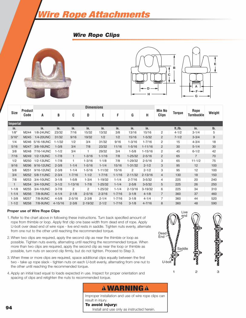
Wire Rope Attachments
94
Wire Rope Clips
B
C
E
F
GH
DA
A B C D E F G H
in. in. in. in. in. in. in. in. in. ft./lb. in. lb.1/8* M244 1/8-24UNC 23/32 7/16 15/32 13/32 3/8 13/16 15/16 2 4-1/2 3-1/4 5
3/16* M245 1/4-20UNC 31/32 9/16 19/32 1/2 1/2 15/16 1-5/32 2 7-1/2 3-3/4 9
1/4 M246 5/16-18UNC 1-1/32 1/2 3/4 31/32 9/16 1-3/16 1-7/16 2 15 4-3/4 18
5/16 M247 3/8-16UNC 1-3/8 3/4 7/8 23/32 11/16 1-5/16 1-11/16 2 30 5-1/4 30
3/8 M248 7/16-14UNC 1-1/2 3/4 1 29/32 3/4 1-5/8 1-15/16 2 45 6-1/2 42
7/16 M249 1/2-13UNC 1-7/8 1 1-3/16 1-1/16 7/8 1-25/32 2-5/16 2 65 7 70
1/2 M250 1/2-13UNC 1-7/8 1 1-3/16 1-1/8 7/8 1-29/32 2-5/16 3 65 11-1/2 75
9/16 M296 9/16-12UNC 2-3/8 1-1/4 1-5/16 1-1/4 15/16 1-31/32 2-1/2 3 95 12 100
5/8 M251 9/16-12UNC 2-3/8 1-1/4 1-5/16 1-11/32 15/16 2 2-1/2 3 95 12 100
3/4 M252 5/8-11UNC 2-3/4 1-7/16 1-1/2 1-7/16 1-1/16 2-11/32 2-13/16 4 130 18 150
7/8 M253 3/4-10UNC 3-1/8 1-5/8 1-3/4 1-19/32 1-1/4 2-7/16 3-5/32 4 225 20 240
1 M254 3/4-10UNC 3-1/2 1-13/16 1-7/8 1-25/32 1-1/4 2-5/8 3-5/32 5 225 26 250
1-1/8 M255 3/4-10UNC 3-7/8 2 2 1-25/32 1-1/4 2-13/16 3-19/32 6 225 34 310
1-1/4 M256 7/8-9UNC 4-1/4 2-1/8 2-5/16 2-3/16 1-7/16 3-1/8 4-1/8 7 360 37 460
1-3/8 M257 7/8-9UNC 4-5/8 2-5/16 2-3/8 2-1/4 1-7/16 3-1/8 4-1/4 7 360 44 520
1-1/2 M258 7/8-9UNC 4-15/16 2-3/8 2-19/32 2-1/2 1-7/16 3-1/8 4-7/16 8 360 48 590
Imperial
Size Product Code Weight
DimensionsMin No Clips Torque Rope
Turnbuckle
Liveend
Saddle
U-bolt
DeadEnd
1 2 3
Proper use of Wire Rope Clips
1. Refer to the chart above in following these instructions. Turn back specified amount ofrope from thimble or loop. Apply first clip one base width from dead end of rope. ApplyU-bolt over dead end of wire rope - live end rests in saddle. Tighten nuts evenly, alternatefrom one nut to the other until reaching the recommended torque.
2. When two clips are required, apply the second clip as near the thimble or loop aspossible. Tighten nuts evenly, alternating until reaching the recommended torque. Whenmore than two clips are required, apply the second clip as near the loop or thimble aspossible, turn nuts on second clip firmly, but do not tighten. Proceed to Step 3.
3. When three or more clips are required, space additional clips equally between the firsttwo - take up rope slack - tighten nuts on each U-bolt evenly, alternating from one nut tothe other until reaching the recommended torque.
4. Apply an initial load equal to loads expected in use. Inspect for proper orientation andspacing of clips and retighten the nuts to recommended torque.
! !WARNINGImproper installation and use of wire rope clips canresult in injury.To avoid injury:
Install and use only as instructed herein.
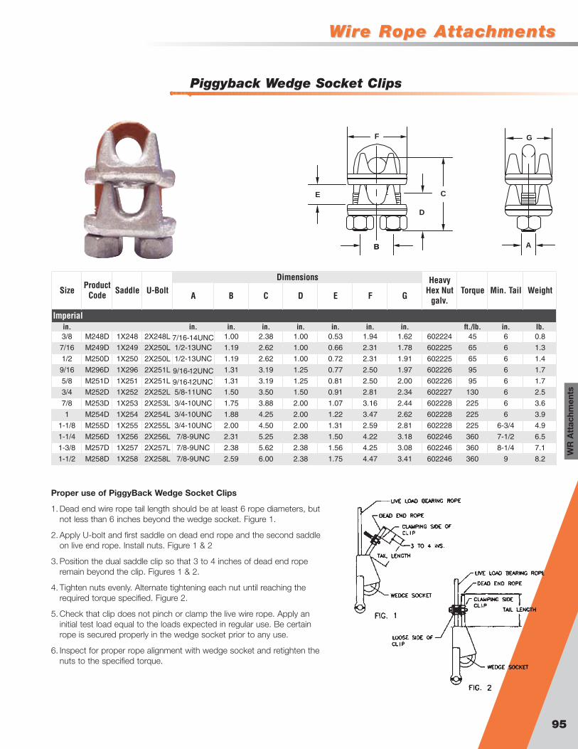
WWirire Rope Attachmentse Rope Attachments
95
WR
Att
achm
ents
Piggyback Wedge Socket Clips
B A
D
C
GF
B
E
A B C D E F G
in. in. in. in. in. in. in. in. ft./lb. in. lb.3/8 M248D 1X248 2X248L 7/16-14UNC 1.00 2.38 1.00 0.53 1.94 1.62 602224 45 6 0.8
7/16 M249D 1X249 2X250L 1/2-13UNC 1.19 2.62 1.00 0.66 2.31 1.78 602225 65 6 1.3
1/2 M250D 1X250 2X250L 1/2-13UNC 1.19 2.62 1.00 0.72 2.31 1.91 602225 65 6 1.4
9/16 M296D 1X296 2X251L 9/16-12UNC 1.31 3.19 1.25 0.77 2.50 1.97 602226 95 6 1.7
5/8 M251D 1X251 2X251L 9/16-12UNC 1.31 3.19 1.25 0.81 2.50 2.00 602226 95 6 1.7
3/4 M252D 1X252 2X252L 5/8-11UNC 1.50 3.50 1.50 0.91 2.81 2.34 602227 130 6 2.5
7/8 M253D 1X253 2X253L 3/4-10UNC 1.75 3.88 2.00 1.07 3.16 2.44 602228 225 6 3.6
1 M254D 1X254 2X254L 3/4-10UNC 1.88 4.25 2.00 1.22 3.47 2.62 602228 225 6 3.9
1-1/8 M255D 1X255 2X255L 3/4-10UNC 2.00 4.50 2.00 1.31 2.59 2.81 602228 225 6-3/4 4.9
1-1/4 M256D 1X256 2X256L 7/8-9UNC 2.31 5.25 2.38 1.50 4.22 3.18 602246 360 7-1/2 6.5
1-3/8 M257D 1X257 2X257L 7/8-9UNC 2.38 5.62 2.38 1.56 4.25 3.08 602246 360 8-1/4 7.1
1-1/2 M258D 1X258 2X258L 7/8-9UNC 2.59 6.00 2.38 1.75 4.47 3.41 602246 360 9 8.2
Dimensions
Imperial
Size Product Code Weight
Heavy Hex Nut
galv.Torque Min. TailSaddle U-Bolt
Proper use of PiggyBack Wedge Socket Clips
1. Dead end wire rope tail length should be at least 6 rope diameters, butnot less than 6 inches beyond the wedge socket. Figure 1.
2. Apply U-bolt and first saddle on dead end rope and the second saddleon live end rope. Install nuts. Figure 1 & 2
3. Position the dual saddle clip so that 3 to 4 inches of dead end roperemain beyond the clip. Figures 1 & 2.
4. Tighten nuts evenly. Alternate tightening each nut until reaching therequired torque specified. Figure 2.
5. Check that clip does not pinch or clamp the live wire rope. Apply aninitial test load equal to the loads expected in regular use. Be certainrope is secured properly in the wedge socket prior to any use.
6. Inspect for proper rope alignment with wedge socket and retighten thenuts to the specified torque.
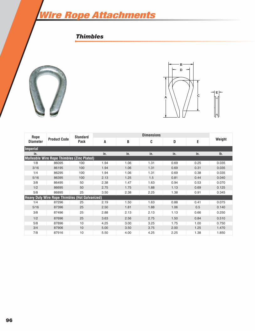
Wire Rope Attachments
96
Thimbles
A B C D E
in. in. in. in. in. in. lb.
1/8 86095 100 1.94 1.06 1.31 0.69 0.25 0.035
3/16 86195 100 1.94 1.06 1.31 0.69 0.31 0.035
1/4 86295 100 1.94 1.06 1.31 0.69 0.38 0.035
5/16 86395 100 2.13 1.25 1.5 0.81 0.44 0.040
3/8 86495 50 2.38 1.47 1.63 0.94 0.53 0.070
1/2 86695 50 2.75 1.75 1.88 1.13 0.69 0.125
5/8 86895 25 3.50 2.38 2.25 1.38 0.91 0.345
1/4 87296 25 2.19 1.50 1.63 0.88 0.41 0.075
5/16 87396 25 2.50 1.81 1.88 1.06 0.5 0.140
3/8 87496 25 2.88 2.13 2.13 1.13 0.66 0.250
1/2 87696 25 3.63 2.56 2.75 1.50 0.84 0.510
5/8 87896 10 4.25 3.00 3.25 1.75 1.00 0.7503/4 87906 10 5.00 3.50 3.75 2.00 1.25 1.470
7/8 87916 10 5.50 4.00 4.25 2.25 1.38 1.850
Malleable Wire Rope Thimbles (Zinc Plated)
Heavy Duty Wire Rope Thimbles (Hot Galvanized)
Imperial
Rope Diameter Product Code WeightStandard
Pack
Dimensions
AC
E
B
D
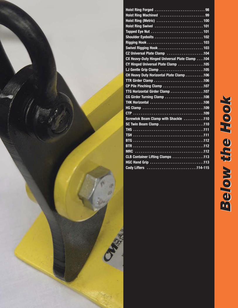
Belo
w t
he H
ook
Belo
w t
he H
ook
Hoist Ring Forged . . . . . . . . . . . . . . . . . . . . . . . . . . . 98Hoist Ring Machined . . . . . . . . . . . . . . . . . . . . . . . . 99Hoist Ring (Metric) . . . . . . . . . . . . . . . . . . . . . . . . . 100Hoist Ring Swivel . . . . . . . . . . . . . . . . . . . . . . . . . . 101Tapped Eye Nut . . . . . . . . . . . . . . . . . . . . . . . . . . . . 101Shoulder Eyebolts . . . . . . . . . . . . . . . . . . . . . . . . . . 102Rigging Hook . . . . . . . . . . . . . . . . . . . . . . . . . . . . . . 103Swivel Rigging Hook . . . . . . . . . . . . . . . . . . . . . . . . 103CZ Universal Plate Clamp . . . . . . . . . . . . . . . . . . . .104CX Heavy-Duty Hinged Universal Plate Clamp . . . .104CY Hinged Universal Plate Clamp . . . . . . . . . . . . . .105LJ Gentle Grip Clamp . . . . . . . . . . . . . . . . . . . . . . . .105CH Heavy Duty Horizontal Plate Clamp . . . . . . . . . .106TTR Girder Clamp . . . . . . . . . . . . . . . . . . . . . . . . . . .106CP Pile Pinching Clamp . . . . . . . . . . . . . . . . . . . . . .107TTG Horizontal Girder Clamp . . . . . . . . . . . . . . . . . .107CG Girder Turning Clamp . . . . . . . . . . . . . . . . . . . . .108THK Horizontal . . . . . . . . . . . . . . . . . . . . . . . . . . . . .108HG Clamp . . . . . . . . . . . . . . . . . . . . . . . . . . . . . . . . .109CTP . . . . . . . . . . . . . . . . . . . . . . . . . . . . . . . . . . . . . .109Screwlok Beam Clamp with Shackle . . . . . . . . . . .110SC Twin Beam Clamp . . . . . . . . . . . . . . . . . . . . . . . .110THS . . . . . . . . . . . . . . . . . . . . . . . . . . . . . . . . . . . . . .111TSH . . . . . . . . . . . . . . . . . . . . . . . . . . . . . . . . . . . . . .111BTG . . . . . . . . . . . . . . . . . . . . . . . . . . . . . . . . . . . . . .112BTR . . . . . . . . . . . . . . . . . . . . . . . . . . . . . . . . . . . . . .112MRC . . . . . . . . . . . . . . . . . . . . . . . . . . . . . . . . . . . . .112CLB Container Lifting Clamps . . . . . . . . . . . . . . . . .113HGC Hand Grip . . . . . . . . . . . . . . . . . . . . . . . . . . . . .113Cady Lifters . . . . . . . . . . . . . . . . . . . . . . . . . . .114-115
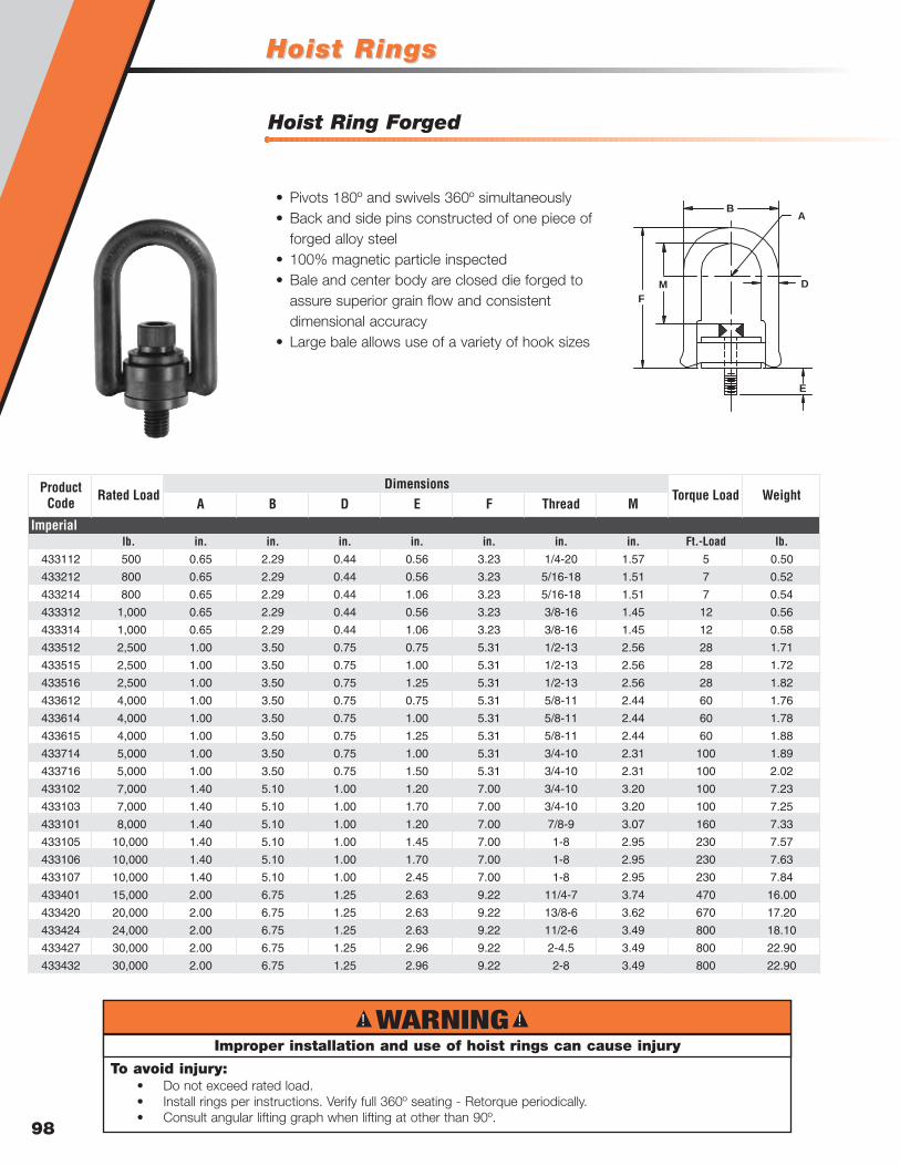
Hoist RingsHoist Rings
98
Hoist Ring Forged
lb. in. in. in. in. in. in. in. Ft.-Load lb.433112 500 0.65 2.29 0.44 0.56 3.23 1/4-20 1.57 5 0.50
433212 800 0.65 2.29 0.44 0.56 3.23 5/16-18 1.51 7 0.52
433214 800 0.65 2.29 0.44 1.06 3.23 5/16-18 1.51 7 0.54
433312 1,000 0.65 2.29 0.44 0.56 3.23 3/8-16 1.45 12 0.56
433314 1,000 0.65 2.29 0.44 1.06 3.23 3/8-16 1.45 12 0.58
433512 2,500 1.00 3.50 0.75 0.75 5.31 1/2-13 2.56 28 1.71
433515 2,500 1.00 3.50 0.75 1.00 5.31 1/2-13 2.56 28 1.72
433516 2,500 1.00 3.50 0.75 1.25 5.31 1/2-13 2.56 28 1.82
433612 4,000 1.00 3.50 0.75 0.75 5.31 5/8-11 2.44 60 1.76
433614 4,000 1.00 3.50 0.75 1.00 5.31 5/8-11 2.44 60 1.78
433615 4,000 1.00 3.50 0.75 1.25 5.31 5/8-11 2.44 60 1.88
433714 5,000 1.00 3.50 0.75 1.00 5.31 3/4-10 2.31 100 1.89
433716 5,000 1.00 3.50 0.75 1.50 5.31 3/4-10 2.31 100 2.02
433102 7,000 1.40 5.10 1.00 1.20 7.00 3/4-10 3.20 100 7.23
433103 7,000 1.40 5.10 1.00 1.70 7.00 3/4-10 3.20 100 7.25
433101 8,000 1.40 5.10 1.00 1.20 7.00 7/8-9 3.07 160 7.33
433105 10,000 1.40 5.10 1.00 1.45 7.00 1-8 2.95 230 7.57
433106 10,000 1.40 5.10 1.00 1.70 7.00 1-8 2.95 230 7.63
433107 10,000 1.40 5.10 1.00 2.45 7.00 1-8 2.95 230 7.84
433401 15,000 2.00 6.75 1.25 2.63 9.22 11/4-7 3.74 470 16.00
433420 20,000 2.00 6.75 1.25 2.63 9.22 13/8-6 3.62 670 17.20
433424 24,000 2.00 6.75 1.25 2.63 9.22 11/2-6 3.49 800 18.10
433427 30,000 2.00 6.75 1.25 2.96 9.22 2-4.5 3.49 800 22.90
433432 30,000 2.00 6.75 1.25 2.96 9.22 2-8 3.49 800 22.90
Imperial
DimensionsWeightProduct
Code Rated LoadA B D
Torque Load E F Thread M
BA
D
E
M
F
• Pivots 180º and swivels 360º simultaneously• Back and side pins constructed of one piece of
forged alloy steel• 100% magnetic particle inspected• Bale and center body are closed die forged to
assure superior grain flow and consistent dimensional accuracy
• Large bale allows use of a variety of hook sizes
! !WARNINGImproper installation and use of hoist rings can cause injury
To avoid injury:• Do not exceed rated load.• Install rings per instructions. Verify full 360º seating - Retorque periodically.• Consult angular lifting graph when lifting at other than 90º.
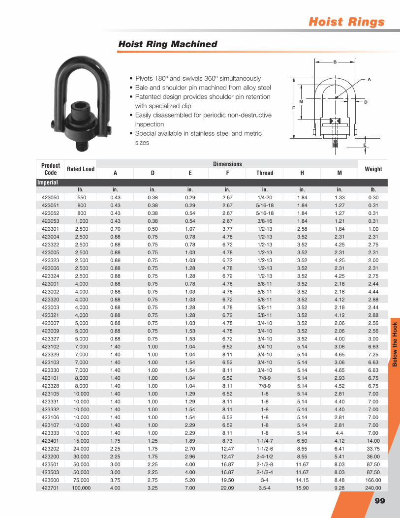
Hoist RingsHoist Rings
99
Hoist Ring Machined
lb. in. in. in. in. in. in. in. lb.423050 550 0.43 0.38 0.29 2.67 1/4-20 1.84 1.33 0.30
423051 800 0.43 0.38 0.29 2.67 5/16-18 1.84 1.27 0.31
423052 800 0.43 0.38 0.54 2.67 5/16-18 1.84 1.27 0.31
423053 1,000 0.43 0.38 0.54 2.67 3/8-16 1.84 1.21 0.31
423301 2,500 0.70 0.50 1.07 3.77 1/2-13 2.58 1.84 1.00
423004 2,500 0.88 0.75 0.78 4.78 1/2-13 3.52 2.31 2.31
423322 2,500 0.88 0.75 0.78 6.72 1/2-13 3.52 4.25 2.75
423005 2,500 0.88 0.75 1.03 4.78 1/2-13 3.52 2.31 2.31
423323 2,500 0.88 0.75 1.03 6.72 1/2-13 3.52 4.25 2.00
423006 2,500 0.88 0.75 1.28 4.78 1/2-13 3.52 2.31 2.31
423324 2,500 0.88 0.75 1.28 6.72 1/2-13 3.52 4.25 2.75
423001 4,000 0.88 0.75 0.78 4.78 5/8-11 3.52 2.18 2.44
423002 4,000 0.88 0.75 1.03 4.78 5/8-11 3.52 2.18 4.44
423320 4,000 0.88 0.75 1.03 6.72 5/8-11 3.52 4.12 2.88
423003 4,000 0.88 0.75 1.28 4.78 5/8-11 3.52 2.18 2.44
423321 4,000 0.88 0.75 1.28 6.72 5/8-11 3.52 4.12 2.88
423007 5,000 0.88 0.75 1.03 4.78 3/4-10 3.52 2.06 2.56
423009 5,000 0.88 0.75 1.53 4.78 3/4-10 3.52 2.06 2.56
423327 5,000 0.88 0.75 1.53 6.72 3/4-10 3.52 4.00 3.00
423102 7,000 1.40 1.00 1.04 6.52 3/4-10 5.14 3.06 6.63
423329 7,000 1.40 1.00 1.04 8.11 3/4-10 5.14 4.65 7.25
423103 7,000 1.40 1.00 1.54 6.52 3/4-10 5.14 3.06 6.63
423330 7,000 1.40 1.00 1.54 8.11 3/4-10 5.14 4.65 6.63
423101 8,000 1.40 1.00 1.04 6.52 7/8-9 5.14 2.93 6.75
423328 8,000 1.40 1.00 1.04 8.11 7/8-9 5.14 4.52 6.75
423105 10,000 1.40 1.00 1.29 6.52 1-8 5.14 2.81 7.00
423331 10,000 1.40 1.00 1.29 8.11 1-8 5.14 4.40 7.00
423332 10,000 1.40 1.00 1.54 8.11 1-8 5.14 4.40 7.00
423106 10,000 1.40 1.00 1.54 6.52 1-8 5.14 2.81 7.00
423107 10,000 1.40 1.00 2.29 6.52 1-8 5.14 2.81 7.00
423333 10,000 1.40 1.00 2.29 8.11 1-8 5.14 4.4 7.00
423401 15,000 1.75 1.25 1.89 8.73 1-1/4-7 6.50 4.12 14.00
423202 24,000 2.25 1.75 2.70 12.47 1-1/2-6 8.55 6.41 33.75
423200 30,000 2.25 1.75 2.96 12.47 2-4-1/2 8.55 5.41 36.00
423501 50,000 3.00 2.25 4.00 16.87 2-1/2-8 11.67 8.03 87.50
423503 50,000 3.00 2.25 4.00 16.87 2-1/2-4 11.67 8.03 87.50
423600 75,000 3.75 2.75 5.20 19.50 3-4 14.15 8.48 166.00
423701 100,000 4.00 3.25 7.00 22.09 3.5-4 15.90 9.28 240.00
F Thread H M
Imperial
DimensionsWeightProduct
Code Rated LoadA D E
D
A
B
E
F
M
• Pivots 180º and swivels 360º simultaneously• Bale and shoulder pin machined from alloy steel• Patented design provides shoulder pin retention
with specialized clip• Easily disassembled for periodic non-destructive
inspection• Special available in stainless steel and metric
sizes
Bel
ow
the
Ho
ok
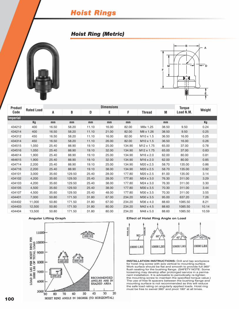
100
Hoist Ring (Metric)
Kg mm mm mm mm mm mm Kg434212 400 16.50 58.20 11.10 16.00 82.00 M8x 1.25 38.50 9.50 0.24
434214 400 16.50 58.20 11.10 21.00 82.00 M8 x 1.26 38.50 9.50 0.25
434312 450 16.50 58.20 11.10 16.00 82.00 M10 x 1.5 36.50 16.00 0.25
434314 450 16.50 58.20 11.10 26.00 82.00 M10 x 1.5 36.50 16.00 0.26
434515 1,050 25.40 88.90 19.10 25.00 134.90 M12 x 1.75 65.00 37.00 0.78
434516 1,050 25.40 88.90 19.10 32.00 134.90 M12 x 1.75 65.00 37.00 0.83
464614 1,900 25.40 88.90 19.10 25.00 134.90 M16 x 2.0 62.00 80.00 0.81
464615 1,900 25.40 88.90 19.10 32.00 134.90 M16 x 2.0 62.00 80.00 0.85
434714 2,200 25.40 88.90 19.10 25.00 134.90 M20 x 2.5 58.70 135.00 0.86
434716 2,200 25.40 88.90 19.10 38.00 134.90 M20 x 2.5 58.70 135.00 0.92
434101 3,000 35.60 129.50 25.40 28.00 177.80 M20 x 2.5 81.00 135.00 3.14
434102 4,200 35.60 129.50 25.40 28.00 177.80 M24 x 3.0 76.30 311.00 3.29
434103 4,200 35.60 129.50 25.40 38.00 177.80 M24 x 3.0 76.30 311.00 3.30
434105 4,500 35.60 129.50 25.40 38.00 177.80 M30 x 3.5 70.30 311.00 3.44
434107 4,500 35.60 129.50 25.40 48.00 177.80 M30 x 3.5 70.30 311.00 3.55
434401 7,000 50.80 171.50 31.80 67.00 234.20 M30 x 3.5 95.00 637.20 7.26
434402 11,000 50.80 171.50 31.80 67.00 234.20 M36 x 4.0 88.60 1085.50 8.21
434403 12,500 50.80 171.50 31.80 80.00 234.20 M42 x 4.5 88.60 1085.50 10.14
434404 13,500 50.80 171.50 31.80 80.00 234.20 M48 x 5.0 88.60 1085.50 10.59
Imperial
DimensionsWeightProduct
Code Rated LoadA B D
Torque Load N.M.E F Thread M
BA
D
E
M
F
INSTALLATION INSTRUCTIONS: Drill and tap workpiecefor hoist ring screw with axis vertical to mounting surface.Work surface should be flat and smooth to provide full 360°flush seating for the bushing flange. (SAFETY NOTE: Someloosening may develop after prolonged service in a perma-nent installation. It is advisable to periodically re-tighten the mounting screw to maintain the specified torque value.)The use of free fit spacers between the bushing flange andmounting surface is not recommended as this will reducethe safe load rating on angularly applied loads. Hoist ringmust be free to swivel 360° and pivot 180° at all times.
Effect of Hoist Ring Angle on LoadAngular Lifting Graph
Hoist RingsHoist Rings
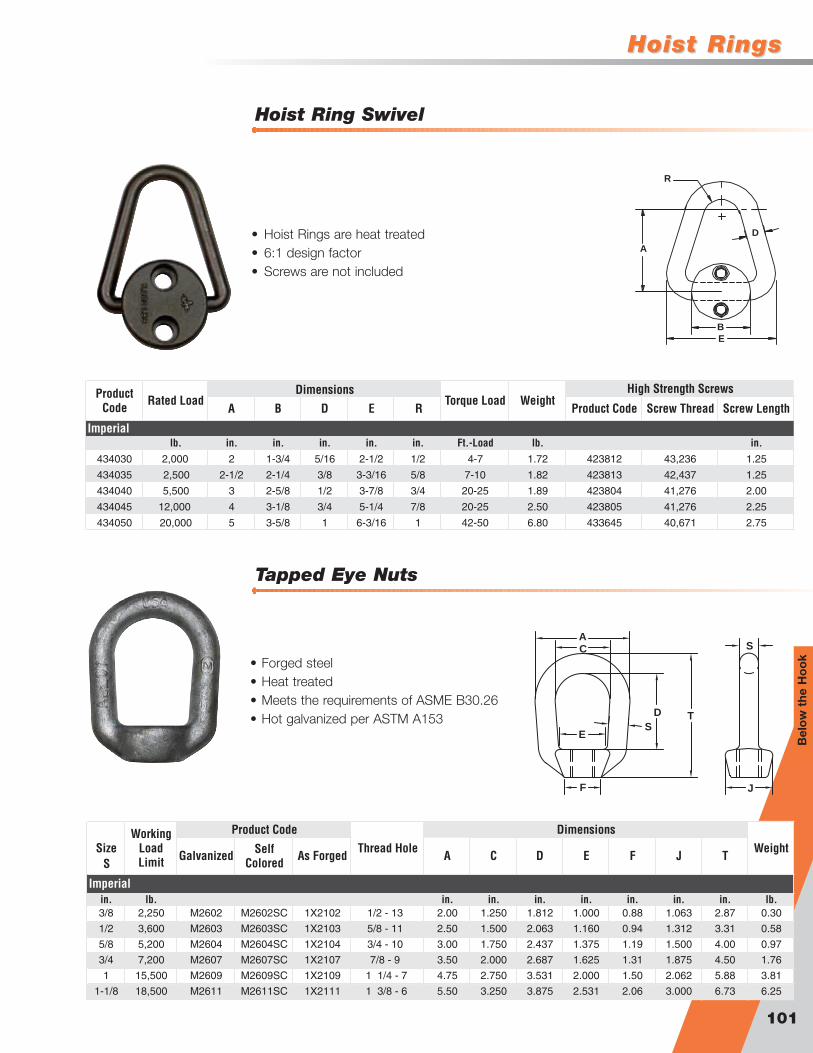
Hoist RingsHoist Rings
101
Hoist Ring Swivel
Tapped Eye Nuts
lb. in. in. in. in. in. Ft.-Load lb. in.434030 2,000 2 1-3/4 5/16 2-1/2 1/2 4-7 1.72 423812 43,236 1.25
434035 2,500 2-1/2 2-1/4 3/8 3-3/16 5/8 7-10 1.82 423813 42,437 1.25
434040 5,500 3 2-5/8 1/2 3-7/8 3/4 20-25 1.89 423804 41,276 2.00
434045 12,000 4 3-1/8 3/4 5-1/4 7/8 20-25 2.50 423805 41,276 2.25
434050 20,000 5 3-5/8 1 6-3/16 1 42-50 6.80 433645 40,671 2.75
Product Code Screw Thread Screw Length
Imperial
R
Dimensions High Strength ScrewsWeightProduct
Code Rated LoadA B D
Torque Load E
D
R
A
B
E
• Hoist Rings are heat treated• 6:1 design factor• Screws are not included
Galvanized Self Colored As Forged A C D E F J T
in. lb. in. in. in. in. in. in. in. lb.3/8 2,250 M2602 M2602SC 1X2102 1/2 - 13 2.00 1.250 1.812 1.000 0.88 1.063 2.87 0.30
1/2 3,600 M2603 M2603SC 1X2103 5/8 - 11 2.50 1.500 2.063 1.160 0.94 1.312 3.31 0.58
5/8 5,200 M2604 M2604SC 1X2104 3/4 - 10 3.00 1.750 2.437 1.375 1.19 1.500 4.00 0.97
3/4 7,200 M2607 M2607SC 1X2107 7/8 - 9 3.50 2.000 2.687 1.625 1.31 1.875 4.50 1.76
1 15,500 M2609 M2609SC 1X2109 1 1/4 - 7 4.75 2.750 3.531 2.000 1.50 2.062 5.88 3.81
1-1/8 18,500 M2611 M2611SC 1X2111 1 3/8 - 6 5.50 3.250 3.875 2.531 2.06 3.000 6.73 6.25
Thread HoleProduct CodeWorking
Load Limit
Dimensions
Imperial
Size WeightS
• Forged steel• Heat treated• Meets the requirements of ASME B30.26• Hot galvanized per ASTM A153
E
A
D
F J
C S
ST
Bel
ow
the
Ho
ok
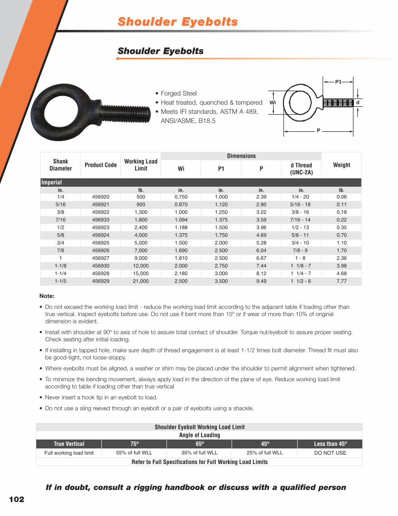
Shoulder EyeboltsShoulder Eyebolts
102
Shoulder Eyebolts
Wi P1 P d Thread (UNC-2A)
in. in. in. in. in. lb.1/4 456920 500 0.750 1.000 2.39 1/4 - 20 0.06
5/16 456921 900 0.870 1.120 2.80 5/16 - 18 0.11
3/8 456922 1,300 1.000 1.250 3.22 3/8 - 16 0.18
7/16 496933 1,800 1.094 1.375 3.59 7/16 - 14 0.22
1/2 456923 2,400 1.188 1.500 3.96 1/2 - 13 0.35
5/8 456924 4,000 1.375 1.750 4.69 5/8 - 11 0.70
3/4 456925 5,000 1.500 2.000 5.28 3/4 - 10 1.10
7/8 456926 7,000 1.690 2.500 6.04 7/8 - 9 1.70
1 456927 9,000 1.810 2.500 6.67 1 - 8 2.36
1-1/8 456930 12,000 2.000 2.750 7.44 1 1/8 - 7 3.98
1-1/4 456928 15,000 2.180 3.000 8.12 1 1/4 - 7 4.68
1-1/5 456929 21,000 2.500 3.500 9.49 1 1/2 - 6 7.77
Imperial
Shank Diameter Product Code Weight
DimensionsWorking Load
Limit
lb.
Wi
P
P1
d
Note:
• Do not exceed the working load limit - reduce the working load limit according to the adjacent table if loading other thantrue vertical. Inspect eyebolts before use. Do not use if bent more than 15º or if wear of more than 10% of originaldimension is evident.
• Install with shoulder at 90º to axis of hole to assure total contact of shoulder. Torque nut/eyebolt to assure proper seating.Check seating after initial loading.
• If installing in tapped hole, make sure depth of thread engagement is at least 1-1/2 times bolt diameter. Thread fit must alsobe good-tight, not loose-sloppy.
• Where eyebolts must be aligned, a washer or shim may be placed under the shoulder to permit alignment when tightened.
• To minimize the bending movement, always apply load in the direction of the plane of eye. Reduce working load limitaccording to table if loading other than true vertical
• Never insert a hook tip in an eyebolt to load.
• Do not use a sling reeved through an eyebolt or a pair of eyebolts using a shackle.
True Vertical 75º 65º 45º Less than 45ºFull working load limit 55% of full WLL 35% of full WLL 25% of full WLL DO NOT USE
Shoulder Eyebolt Working Load LimitAngle of Loading
Refer to Full Specifications for Full Working Load Limits
If in doubt, consult a rigging handbook or discuss with a qualified person
• Forged Steel• Heat treated, quenched & tempered• Meets IFI standards, ASTM A 489,
ANSI/ASME, B18.5

Rigging HooksRigging Hooks
103
Swivel Rigging Hook
Rigging Hook
C
L R
B
A
K
G
H K
D
T
OJ
C
LR
B
A
I
G
H
S
D
T
O
WLL Product
Code
w/o latch
Product Code
w/ latchWLL
Product
Code
w/o latch
Product Code
w/ latchA B C D G H J K L O R T
ton ton in. in. in. in. in. in. in. in. in. in. in. in. lb.1 M6402A M6502A 3/4 M6402C M6502C 1.50 0.75 0.38 3.06 0.87 1.05 0.93 0.63 4.37 0.93 3.13 0.87 0.66
1-1/2 M6403A M6503A 1 M6403C M6503C 1.75 0.88 0.44 3.33 0.94 1.11 0.97 0.71 5.04 0.97 3.66 0.97 1.122 M6404A M6504A 1-1/2 M6404C M6504C 2.13 1.13 0.50 3.67 1.06 1.21 1.06 0.88 5.63 1.06 4.09 1.03 1.463 M6405A M6505A 2 M6405C M6505C 2.50 1.25 0.63 4.20 1.27 1.43 1.19 0.94 6.55 1.16 4.67 1.16 2.425 M6407A M6507A 3 M6407C M6507C 3.06 1.56 0.75 5.11 1.44 1.63 1.50 1.31 7.97 1.41 5.78 1.53 4.107 M6409A M6509A 5 M6409C M6509C 3.88 2.00 0.94 6.24 1.82 2.01 1.78 1.68 10.07 1.69 7.31 1.94 8.1611 M6411A M6511A 7-1/2 M6411C M6511C 4.69 2.44 1.13 7.89 2.25 2.63 2.38 1.88 12.41 2.19 9.03 2.52 15.6015 M6415A M6515A 10 M6415C M6515C 5.34 2.84 1.25 8.37 2.59 2.94 2.50 2.19 14.05 2.30 10.21 2.54 21.5822 M6422A M6522A 15 M6422C M6522C 6.63 3.50 1.56 10.19 3.00 3.50 3.30 2.69 17.37 3.12 12.81 2.73 39.89
DimensionsAlloy Carbon
Imperial
Weight
WLL Product
Code w/o latch
Product Code
w/ latchWLL
Product Code
w/o latch
Product Code
w/ latchA B C D G H I L R S T O
ton ton in. in. in. in. in. in. in. in. in. in. in. in. lb.1 M3402A M3502A 3/4 M3402C M3502C 2.00 1.11 1.25 3.06 0.87 1.05 0.63 5.83 4.63 0.38 0.87 0.93 1.05
1-1/2 M3403A M3503A 1 M3403C M3503C 2.50 1.38 1.50 3.33 0.94 1.11 0.71 6.83 5.44 0.50 0.97 0.97 1.562 M3404A M3504A 1-1/2 M3404C M3504C 3.00 1.65 1.75 3.67 1.06 1.21 0.88 7.76 6.25 0.63 1.03 1.06 2.503 M3405A M3505A 2 M3405C M3505C 3.00 1.65 1.75 4.20 1.27 1.43 0.94 8.40 6.49 0.063 1.16 1.16 3.205 M3407A M3507A 3 M3407C M3507C 3.50 1.77 2.00 5.11 1.44 1.63 1.31 9.76 7.53 0.75 1.53 1.41 5.367 M3409A M3509A 5 M3409C M3509C 4.75 2.39 2.75 6.24 1.82 2.01 1.68 12.42 9.67 1.00 1.94 1.69 10.5611 M3411A M3511A 7-1/2 M3411C M3511C 5.50 2.55 3.25 7.69 2.25 2.63 1.88 14.89 12.06 1.13 2.46 2.22 19.0015 M3415A M3515A 10 M3415C M3515C 6.00 2.47 3.50 8.37 2.59 2.94 2.19 15.79 11.95 1.25 2.62 2.23 26.7522 M3422A M3522A 15 M3422C M3522C 7.75 3.82 4.75 10.19 3.00 3.50 2.69 21.18 16.68 1.50 2.74 3.05 51.80
DimensionsAlloy Carbon
Imperial
Weight
• Built in distortion detectors• Load rating marked on each hook body• Proof load 2 times WLL• Design factor 5:1• Pre-drilled latch tab allows addition of latch• Carbon hooks have a clear protective
coating to resist rust and for cleanerhandling (use suffix “C” when orderingcarbon clear finish, use suffix “G” whenordering hot dip galvanized)
• Design factor 5:1• Pre-drilled for latches• Hook and latch assemblies furnished
separately• Painted orange• Carbon swivel hooks are technically
advanced Micro-alloy which requiresno secondary heat treat
• Alloy swivel hooks are heat treatedquenched and tempered
Bel
ow
the
Ho
ok

Camlok Clamps
CX Heavy-Duty Hinged Universal Plate Clamp
CZ Universal Plate Clamp
104
Min MaxA B C D E F G H
lb. in. in. in. in. in. in. in. in. in. lb.CZ920.5 120 1,100 0 to 5/8 3.898 7.677 1.142 1.299 1.850 1.969 1.890 0.433 3.3CZ921.5 350 3,300 0 to 3/4 4.961 8.858 1.969 1.929 2.756 3.228 2.165 0.472 6.6CZ922 450 4,400 0 to 1-1/4 7.559 12.283 3.150 2.953 3.780 3.937 3.189 0.787 17.6CZ923 675 6,600 0 to 1-1/4 7.559 12.283 3.150 2.953 3.780 3.937 3.189 1.181 22.0CZ924 1,100 8,800 0 to 1-1/4 7.756 14.606 3.150 2.677 3.661 5.079 0.787 1.181 26.5CZ924/L* 1,100 8,800 1-1/8 to 2- 8.976 15.354 3.150 2.677 3.661 5.079 0.787 1.181 39.7CZ926 1,600 13,200 0 to 2 11.535 19.055 3.504 3.740 5.630 5.079 0.984 1.378 46.3CZ928 2,150 17,600 0 to 2 11.535 19.370 3.504 3.740 5.630 5.079 0.984 1.654 57.3CZ928/L* 2,150 17,600 2 to 4 14.252 20.630 3.504 4.488 5.630 5.079 0.984 1.654 70.5CZ9210 3,350 22,000 0 to 2 11.535 21.457 4.331 3.740 5.630 5.472 0.984 1.772 66.1CZ9210/L 3,350 22,000 2 to 4 14.252 21.457 4.331 4.488 5.630 5.472 0.984 1.772 81.6CZ9215* 6,650 33,000 0 to 2 14.173 24.134 5.118 4.921 6.378 8.031 1.772 2.165 165.3CZ9215/L* 6,650 33,000 2 to 4 18.110 26.693 5.118 6.890 6.378 8.031 1.772 2.165 194.0CZ9220* 8,850 44,000 0 to 2-1/2 18.189 29.724 5.118 6.496 8.268 9.252 1.772 2.559 271.2CZ9220/L* 8,850 44,000 2-1/2 to 5 22.047 31.693 5.118 7.677 8.268 9.252 1.772 2.559 299.8CZ9230* 13,250 66,000 0 to 2-1/2 18.189 28.819 2.362 6.496 8.268 11.614 2.559 - 429.9
Imperial
WeightDimensions
Model Jaw Capacity
Working Load Limit
lb.
Min MaxA B C D E F G H I
lb. in. in. in. in. in. in. in. lb.CX3 1,000 6,600 0 to 1-1/4 7.756 20.276 2.638 5.433 0.748 2.677 3.661 3.189 4.331 26.5CX6 2,650 13,200 0 to 2 11.496 29.016 3.740 6.929 1.102 3.740 5.630 5.394 7.402 83.8CX6/L* 2,650 13,200 2 to 4 14.449 30.906 3.858 7.087 1.102 4.528 5.630 5.315 7.402 105.8CX8* 3,550 17,600 0 to 2 11.496 29.016 3.858 6.929 1.102 3.740 5.630 5.354 8.268 86.0CX8/L* 3,550 17,600 2 to 4 14.449 30.906 3.858 7.087 1.102 4.528 5.630 5.354 8.268 112.4CX10* 4,400 22,000 0 to 2 14.173 35.551 4.331 7.677 1.299 4.921 6.378 6.693 8.780 134.5CX10/L* 4,400 22,000 2 to 4 17.559 36.260 4.409 7.677 1.299 6.614 6.378 6.693 8.780 167.5
Imperial
WeightDimensions
Model Jaw Capacity
Working Load Limit
lb. in. in. in.
• Body of clamp is welded construction• Can be used to lift plate from horizontal to
vertical position and vice versa• Standard clamp is fitted with a hook ring that
can be replaced with a short length of chainand master link
• Clamp jaws and pads are manufactured fromhigh tensile steel
• Designed to handle plate at any angle• Can be used to lift plate from horizontal to
vertical position and vice versa• Vertically racked plates can be turned over
due to the in-built lifting eye and link• Fitted with a cam operated closing
mechanism that can be replaced with a chainpull open/close mechanism
E
A
D F
B
C
G
H
E
A
D
F
B
G
H
C
I
*Not Stocked
*Not Stocked

Camlok ClampsCamlok Clamps
LJ Gentle Grip Clamp
CY Hinged Universal Plate Clamp
105
Bel
ow
the
Ho
ok
Min MaxA B C D E F G H I
lb. lb. in. in. in. in. in. in. in. in. in. in.CY1 450 2,200 0 to 3/4 4.961 10.630 1.969 1.929 2.756 3.740 2.480 0.472 0.906CY2 900 4,400 0 to 1-1/4 7.559 15.039 3.150 2.953 3.780 5.197 3.622 0.787 1.181CY3 1,350 6,600 0 to 1-1/4 7.559 15.039 3.150 2.953 3.780 5.197 3.622 0.787 1.181
Imperial
DimensionsModel Jaw Capacity
Working Load Limit
Min MaxA B C D E F
lb. lb. in. in. in. in. in. in. in. lb.LJ0.5 60 1,100 0 to 3/8 5.000 7.874 2.165 2.047 2.717 2.992 7.7LJ1.5 400 3,300 0 to 3/4 8.465 13.583 3.346 2.953 5.315 4.646 26.5
Imperial
WeightDimensions
Model Jaw Capacity
Working Load Limit
• Hinged hook ring enabling the clamp tobe used at any angle
• Fitted with a cam operated closingmechanism that can be replaced with achain pull open/close mechanism
• Fitted with hardened serrated teethjaws and pads that are suitable forgripping steel
• Designed to lift plates without marking ordamaging the surface finish
• Particularly suitable for lifting thin gauge steelplate, aluminum and stainless steel
E
A
DG
B
C
FH
I
120
90
30
LOAD
E
A
DF
B
C
CY1 CY2 CY3
degrees lb. lb. lb.0-30 4,400 8,800 13,200
30-90 2,200 4,400 6,600
90-120 1,100 2,200 3,300
Imperial
AngleModel Code
Safe loads for two clamps

Camlok Clamps
CH Heavy Duty Horizontal Plate Clamp
TTR Girder Clamp
106
Min MaxA B C D E F
lb. lb. in. in. in. in. in. in. in. lb.TTRO.75 90 1,600 1/4 to 5/8 5.375 7.500 2.000 1.750 2.375 3.500 7.7TTR1.5 350 3,300 1/4 to 1 7.500 10.625 2.625 2.625 3.000 4.875 22.0TTR3* 700 6,600 1/4 to 1 8.250 9.875 3.500 2.625 3.375 5.000 26.5
Imperial
WeightDimensions
Model Flange Working Load Limit
E
A
D
F
B
C
A B C D E F G
lb. in. in. in. in. in. in. in. lb.CH1 2,200 1/4 to 1-1/4 0.591 3.228 2.362 3.937 1.260 1.732 0.512 13.2CH2 4,400 1/4 to 1-1/4 1.181 3.228 2.362 3.937 1.969 2.874 0.709 24.3CH2/L 4,400 3/4 to 2 1.181 3.228 2.362 3.937 1.969 2.874 0.709 26.5CH4 8,800 1/4 to 1-1/4 1.575 4.409 3.150 3.937 2.520 3.622 0.984 37.5CH4/L 8,800 2 to 4 1.575 4.409 3.150 3.937 2.520 3.622 0.984 50.7CH6 13,200 1/4 to 3 2.165 6.772 3.937 5.118 3.543 5.118 1.378 101.4CH6/L 13,200 2 to 5 2.165 6.772 3.937 5.118 3.543 5.118 1.378 123.5CH8 17,600 1/4 to 3 2.165 6.772 4.134 5.118 3.543 5.118 1.378 116.8
CH8/L 17,600 2 to 5 2.165 6.772 4.134 5.118 3.543 5.118 1.378 132.3CH10 22,000 1/4 to 4 2.559 8.465 4.724 5.906 4.488 5.118 1.378 209.4CH10/L 22,000 2 to 6 2.559 8.465 4.724 5.906 4.488 5.118 1.378 238.1HH8* 17,600 1/4 to 2 2.165 6.614 4.134 5.118 4.134 5.118 3.543 46.3HH8/L 17,600 2 to 4 2.165 6.614 4.134 5.118 3.543 4.488 1.378 61.7
Imperial
WeightDimensions
Model Working Load Limit Jaw Capacity
in.
• Designed to lift and transport structural steelbeams in horizontal position
• Clamp designed with the hook as near aspossible to the center of gravity of the beam
• Long beams should be lifted using 2clamps attached to opposite beam flanges
• Used in pairs the CH clamp is designed forloading process machines and to lift andtransport sheet steel plate in horizontalposition
• Standard smooth jaw can be replaced withserrated hardened steel teeth by request
• Designed to be used with 2 legged slings only
*Not Stocked
*Not Stocked
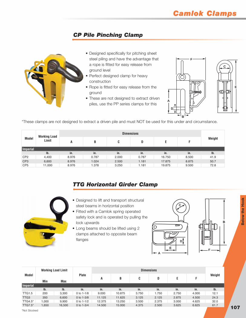
Camlok ClampsCamlok Clamps
TTG Horizontal Girder Clamp
CP Pile Pinching Clamp
107
Bel
ow
the
Ho
ok
A B C D E F
lb. in. in. in. in. in. in. lb.CP2 4,400 8.976 0.787 2.000 0.787 16.750 8.500 41.9CP3 6,600 8.976 1.024 2.500 1.181 17.875 8.875 50.7CP5 11,000 8.976 1.378 3.250 1.181 19.875 9.500 72.8
Imperial
WeightDimensions
Model Working Load Limit
Min MaxA B C D E F
lb. lb. in. in. in. in. in. in. in. lb.TTG1.5 200 3,300 0 to 1-1/8 9.000 10.875 3.750 1.750 2.750 4.000 12.1TTG3 350 6,600 0 to 1-3/8 11.125 11.625 3.125 2.125 2.875 4.500 24.3TTG4.5* 1,000 9,900 0 to 1-1/2 12.375 13.250 3.500 2.375 3.000 4.625 32.0TTG7.5* 1,650 16,500 0 to 1-3/4 14.500 15.000 4.375 2.500 3.625 6.625 61.7
Imperial
WeightDimensions
Model PlateWorking Load Limit
• Designed to lift and transport structuralsteel beams in horizontal position
• Fitted with a Camlok spring operatedsafety lock and is operated by pulling thelock upwards
• Long beams should be lifted using 2clamps attached to opposite beamflanges
E
A
D
F
B
C
E
A
D
F
B
C
• Designed specifically for pitching sheetsteel piling and have the advantage thata rope is fitted for easy release fromground level
• Perfect designed clamp for heavyconstruction
• Rope is fitted for easy release from theground
• These are not designed to extract drivenpiles, use the PP series clamps for this
*These clamps are not designed to extract a driven pile and must NOT be used for this under and circumstance.
*Not Stocked
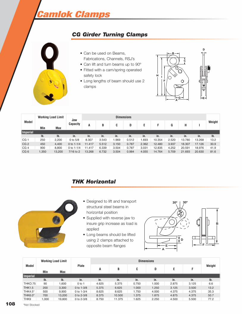
Camlok Clamps
THK Horizontal
CG Girder Turning Clamps
108
Min MaxA B C D E F G H I
lb. lb. in. in. in. in. in. in. in. in. in. in. lb.CG 1 250 2,200 0 to 5/8 8.307 3.543 1.969 0.512 1.693 10.354 2.520 13.780 13.268 13.2CG 2 450 4,400 0 to 1-1/4 11.417 5.512 3.150 0.787 2.362 12.480 3.937 18.307 17.126 30.9CG 4 900 8,800 0 to 1-1/4 11.417 6.339 3.504 0.787 3.031 12.835 4.252 20.591 18.976 41.9CG 6 1,350 13,200 7/16 to 2 13.268 6.732 3.504 0.984 4.055 14.764 5.709 21.693 20.630 81.6
Imperial
WeightDimensions
Model Jaw Capacity
Working Load Limit
Min MaxA B C D E F
lb. lb. in. in. in. in. in. in. in. lb.THKO.75 90 1,600 0 to 1 4.625 5.375 0.750 1.000 2.875 3.125 6.6THK1.5 200 3,300 0 to 1-3/8 5.375 6.625 1.000 1.250 3.125 3.500 13.2THK4.5* 500 9,900 0 to 1-3/4 8.625 8.625 1.750 4.000 4.375 4.375 35.3THK6.0* 700 13,200 0 to 2-3/8 8.375 10.500 1.375 1.875 4.875 4.375 50.7THK9 1,000 19,800 0 to 2-3/8 8.750 11.375 1.625 2.250 4.500 5.500 77.2
Imperial
WeightDimensions
Model PlateWorking Load Limit
• Designed to lift and transportstructural steel beams inhorizontal position
• Supplied with reverse jaw toinsure grip increase as load isapplied
• Long beams should be liftedusing 2 clamps attached toopposite beam flanges E
A
D
F
B
C
30º 30º
EA
D
F
B
G
H
C
I
• Can be used on Beams,Fabrications, Channels, RSJ’s
• Can lift and turn beams up to 90º• Fitted with a cam/spring operated
safety lock• Long lengths of beam should use 2
clamps
*Not Stocked

Camlok ClampsCamlok Clamps
CTP
HG
109
Bel
ow
the
Ho
ok
Min MaxA B C D E F G
lb. lb. in. in. in. in. in. in. in. in. lb.HG0.5 100 1,100 0 to 3/8 1.654 9.055 5.827 0.394 2.165 3.110 1.969 11.0HG1 150 2,000 0 to 5//8 3.661 11.698 8.268 0.630 2.638 4.488 2.638 26.5HG2 450 4,400 0 to 3/4 4.331 16.378 12.008 0.787 4.016 6.260 3.150 48.5HG3* 700 6,600 0 to 3/4 4.331 16.378 12.008 0.787 4.016 6.260 3.150 59.5HG4* 900 8,800 0 to 3/4 4.724 13.189 12.008 0.787 4.016 6.220 3.150 70.5
Imperial
WeightDimensions
Model Jaw CapacityWorking Load Limit
Min Max Min Max
lb. in. in. in. in. in. in. in. lb.CTP1 2,200 2-3//8 to 5-7/8 0.035 3.740 7.283 3.228 4.291 1.024 2.598 2.874 6.299 6.024 4.134 2.953 0.866 4.9CTP2 4,400 3 to 7-7/8 0.045 4.921 9.843 4.173 6.102 1.654 3.543 3.937 10.236 8.071 5.472 5.118 0.787 21.8CTP3 8,800 3 to 7-7/8 0.055 5.315 10.236 5.039 6.732 1.969 4.331 4.921 12.205 8.661 6.102 5.906 0.866 38.6
H J K
Dimensions
D E F G
Imperial
WeightModel Working Load Limit
Jaw Capacity A B
C
Min Curve Radius
in. in. in. in. in. in. in.
A
F
B
G H
E DJ
K
C
A
F
B
G
C
E
• Can be used on hot rolled structural steelplates
• Can be used to lift stainless steel plates orplates with harden surfaces due to cold rolling
• Lift plates from horizontal to vertical positionsand vice versa through 180º
• Clamp has serrated teeth and will mark plate
• Adjustable to fit variousflange widths
• Pre lubricated ballbearings on each unit
• Easily attaches Hoist,Pulleys and Slings
*Not Stocked
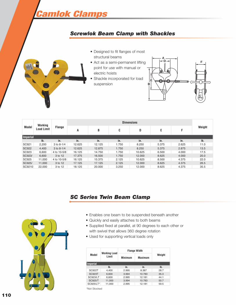
Camlok Clamps
SC Series Twin Beam Clamp
Screwlok Beam Clamp with Shackles
110
A B C D E F
lb. in. in. in. in. in. in. in. lb.SC921 2,200 3 to 8-1/4 12.625 12.125 1.750 8.250 5.375 2.625 11.0SC922 4,400 3 to 8-1/4 12.625 12.875 1.750 8.250 5.375 2.875 13.5SC923 6,600 4 to 10-5/8 16.125 14.750 1.750 10.625 6.500 4.000 17.5SC923/ 6,600 3 to 12 17.375 16.500 1.750 12.000 8.625 4.000 20.0SC925 11,000 4 to 10-5/8 16.125 15.375 2.125 10.625 8.500 4.375 22.0SC925/ 11,000 3 to 12 17.125 17.125 2.125 12.000 8.625 4.375 26.5SC9210 22,000 3 to 12 18.125 20.000 3.250 12.000 8.625 4.375 35.5
Imperial
WeightModel Working Load Limit Flange
Dimensions
Minimum Maximum
lb. in. in. lb.SC922T 4,400 2.995 8.387 28.7SC923T 6,600 3.994 10.783 35.3
SC923/LT 6,600 2.995 12.181 44.1SC925/T 11,000 3.994 10.783 50.7
SC925/LT* 11,000 2.995 12.181 59.5
Imperial
WeightModel Working Load Limit
Flange Width
• Designed to fit flanges of moststructural beams
• Act as a semi-permanent liftingpoint for use with manual orelectric hoists
• Shackle incorporated for loadsuspension
• Enables one beam to be suspended beneath another• Quickly and easily attaches to both beams• Supplied fixed at parallel, at 90 degrees to each other or
with swivel that allows 360 degree rotation• Used for supporting vertical loads only
E
B
AD F
C
*Not Stocked

Camlok ClampsCamlok Clamps
THS
111
Bel
ow
the
Ho
ok
TSH
A B C D E F G H
lb. in. in. in. in. in. in. in. lb.THS0.75 1,600 0 to 3/4 10.039 3.819 1.969 0.591 2.756 3.150 0.472 0.591 6.6THS1.5 3,300 0 to 1-3/8 13.189 4.724 2.756 0.787 3.150 3.543 0.591 0.669 13.2THS3 9,900 0 to 1-3/4 17.717 7.717 3.543 2.323 4.331 4.331 0.787 1.181 37.5
Imperial
WeightDimensions
Model Working Load Limit Jaw Capacity
in. in.
A B C D E F G H
lb. in. in. in. in. in. in. in. lb.TSH1.5 3,300 0 to 1-1/4 5.118 10.039 2.559 4.528 2.953 5.000 1.024 3.701 15.4TSH3 6,600 0 to 2 6.693 11.417 2.913 4.921 3.346 5.669 1.181 4.646 24.3TSH5 11,000 0 to 3-1/8 10.039 18.504 5.118 6.890 5.315 9.449 1.969 6.890 59.5
Imperial
WeightDimensions
Model Working Load Limit Jaw Capacity
in. in.
E
A
D
B
C
A
F
B
G
C
E
H
D
• Spring lever for locking into place• Can be used in single or 2 leg slings• Use lifting beams for longer plates• Do not use with endless or 3 or 4 leg slings• Do not exceed 60º angle when lifting• Do not lift plates with a temperature of
120º C (250ºF) or higher• Do not use to lift stainless steel, lead or
copper
• Offer the best means of holding andsecuring loads
• High force screw threads• Hardened steel jaws• Swivel jaws increases grip if plate moves• Not recommended for lifting applications
F
G
H

Camlok Clamps
MRC Multi Rail Grabs
BTG
112
BTR
A B C D E(Mouth)
F(Pressure Line)
lb. in. in. in. in. in. in. in. lb.BTG1500/3 3,300 1-1/2 to 4-3/4 5.315 5.315 0.709 7.087 6.496 3.937 75.0BTG3000/3 6,600 2 to 7 6.890 3.937 1.024 12.205 9.646 6.890 132.3BTG3000L/3 6,600 3-1/2 to 8-5/8 6.890 3.937 1.024 12.205 9.646 6.890 172.0
Imperial
WeightModelWorking
Load Limit(Per set of 3)
Jaw Capacity (Z)
Dimensions
Minimum Maximum
lb. in. in. lb.BTR2.5/700 5,500 11 27 304.2
BTR2.5/1100 5,500 28 43 368.2BTR3.5/600 7,700 12 23 291.0
BTR3.5/1000 7,700 24 39 352.7BTR3.5/1500 7,700 40 59 385.8
Imperial
WeightModel Working Load Limit
Jaw Capacity
lb. in. in. lb.MRC4 11,000 4 441.0MRC5 11,000 5 507.0MRC6* 13,200 6 584.0MRC7* 15,400 7 650.0MRC8* 17,000 8 727.0
Min 37 in.Overall size depends on
type and number of rails
Imperial
WeightModel Working Load Limit
Number of Rails Width
• Lift pipe diameters up to 60”• Fitted with rubber pads to
protect pipe• Automatic open/close device• Lifts and positions directly
into trench• Adjustable jaws to
accommodate various sizepipes
• Solid construction design• Sold in sets of 3 with chain
slings attached• Simple handling• Large jaw capacity• Light weight design• Service friendly
• Modular design• Various combo sections can fit
onto one scissor lift• Alternate combo sections can
be purchased separately • Allows for fast handling of bulk
rails
*Not Stocked

HGC
CLB Container Lifting Lugs
113
Bel
ow
the
Ho
ok
! !WARNINGImproper installation and use of clamps can cause injury
If not properly installed, operated and maintained, the use of all mechanical equipment presents the possibility ofpersonal injury or property damage. Before using lifting clamps, become familiar with applicable installation,operation and maintenance requirements. Clamps should be used only by authorized, properly trained operators.
To avoid injury:• Inspect clamps and equipment before use. Do not use if components are bent, elongated, gouged, nicked
excessively, worn, or damaged. Make sure that nut, bolts, pins and other fasteners are tightened andsecure. Make sure clamps are functional and will grip the load.
• Do not exceed the clamps’ rated load or working load limit of other lifting equipment components.• Lift only one plate at a time when using lifting clamps.• Do not lift unbalanced loads. Avoid sudden jerks when applying the load. Rapid load application can
produce overloading.• Use clamps and lifting equipment only if authorized and properly trained.• Always stand clear when lifting and lowering.• Use more than one clamp suspended from a lifting beam when lifting long loads.• Always gently lift and lower.
A B C D E F G H
Imperiallb. in. in. in. in. in. in. in. in. lb.
HGC 500 0 to 3/8 4.25 7.25 3.875 1.875 2.125 0.875 0.375 5.125 2.0
WeightModel Working Load Limit Plate
Dimensions
in.
• Additional lever in clamping mechanismprovides a very high gripping force
• Can be used to lift plate from horizontal tovertical position and vice versa
B
G
C
H
A
D
A B C D E F G
lb. in. in. in. in. in. in. lb.CLB32 70,500 5.984 7.126 1.772 1.457 2.874 2.953 1.575 39.7CLB40 88,100 5.984 7.126 1.772 1.457 2.874 2.953 1.575 39.7
Imperial
WeightDimensions
ModelWorking Load
Limit(Per set of 4)
in.
F = Thickness
E
AF
B
C
D
G
20
• Spring loaded bolt to prevent accidental release• Mounted at the side of the container in either
upper or lower holes• Easy installation and removal• Designed to eliminate the dangerous use of
standard hooks

Cady Lifters
Crane Forks
Cady Lifters
114
Cady Lifters represents a complete line of below the hook attachments for efficiently handling goods inindustrial, construction, and related environments. The Cady team of welders conform to the StructuralWelding Code of the American Welding Society, thus ensuring the consistency of the products manufactured.All products conform to the requirements of ANSI/ASME B30.20 for Below-the-Hook Lifting Devices.
In addition to the standard products shown here, custom solutions exist to satisfy the most challenging lifts.Products such as tongs, scissors, and grabs may be tailored to the exact application.
Complete information for all Cady Lifters is available in catalog ICL-10 or at www.cadylifters.com.
Crane forks are ideal for handling palletized loads in areassuch as loading docks, crowded or unpaved storageareas, and railroad yards. They are also used frequentlyto load barges, gondolas, and open top trucks.
All Cady crane forks are counter balanced to hang levelwhen empty and to increase the rate of handling.Counterweight balances the lifter structure only, not theload. The load is centered under the lifting bail for a levellift. All crane forks are load tested and a test certificate issupplied with each unit.
Capacity 1/4 to 10 tons
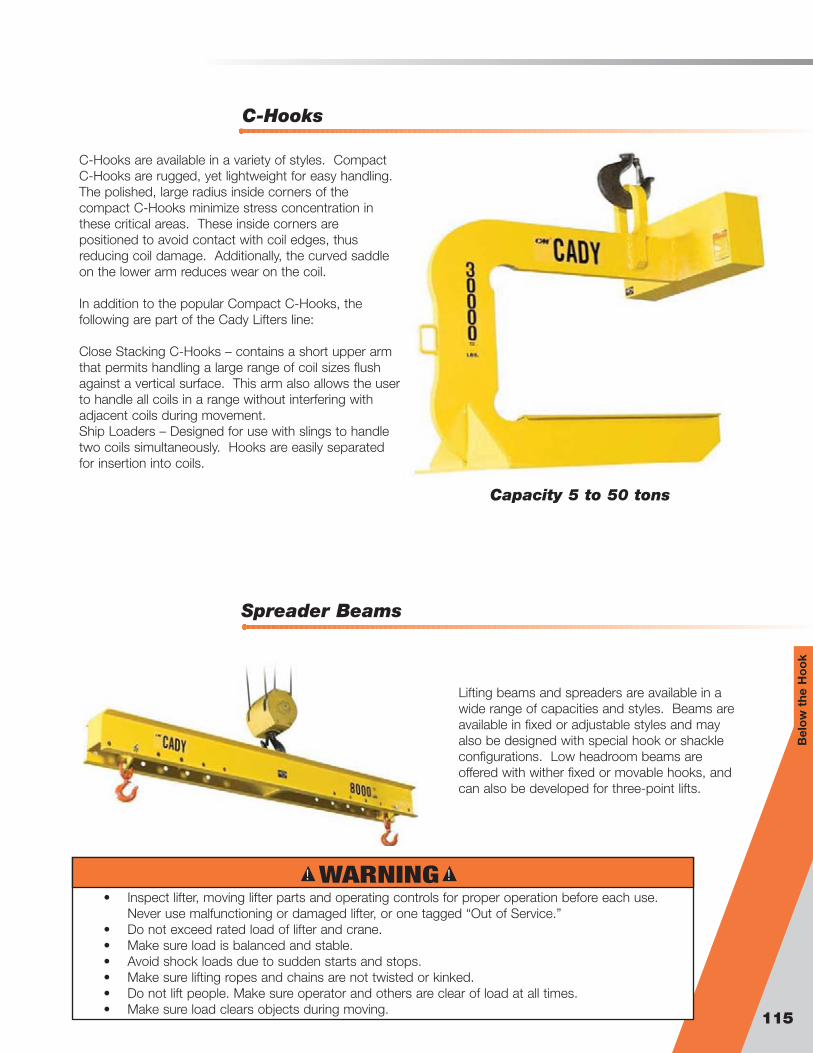
Spreader Beams
C-Hooks
115
Bel
ow
the
Ho
ok
C-Hooks are available in a variety of styles. CompactC-Hooks are rugged, yet lightweight for easy handling.The polished, large radius inside corners of thecompact C-Hooks minimize stress concentration inthese critical areas. These inside corners arepositioned to avoid contact with coil edges, thusreducing coil damage. Additionally, the curved saddleon the lower arm reduces wear on the coil.
In addition to the popular Compact C-Hooks, thefollowing are part of the Cady Lifters line:
Close Stacking C-Hooks – contains a short upper armthat permits handling a large range of coil sizes flushagainst a vertical surface. This arm also allows the userto handle all coils in a range without interfering withadjacent coils during movement. Ship Loaders – Designed for use with slings to handletwo coils simultaneously. Hooks are easily separatedfor insertion into coils.
Lifting beams and spreaders are available in awide range of capacities and styles. Beams areavailable in fixed or adjustable styles and mayalso be designed with special hook or shackleconfigurations. Low headroom beams areoffered with wither fixed or movable hooks, andcan also be developed for three-point lifts.
Capacity 5 to 50 tons
! !WARNING• Inspect lifter, moving lifter parts and operating controls for proper operation before each use.
Never use malfunctioning or damaged lifter, or one tagged “Out of Service.”• Do not exceed rated load of lifter and crane.• Make sure load is balanced and stable.• Avoid shock loads due to sudden starts and stops.• Make sure lifting ropes and chains are not twisted or kinked.• Do not lift people. Make sure operator and others are clear of load at all times.• Make sure load clears objects during moving.

Steerman
116
Steerman Load Movers utilize a three-point system comprised of a steerable front framewith turntable and wheel boxes along with a set of rear trolleys. This permits the user toeffortlessly maneuver in any direction without re-positioning the load.
These products feature specially developed composite wheels machined from solid stockto provide extremely low rolling resistance. Additionally, the unique Steerman turntableweighs only 20% of the steel equivalent, but has superior impact resistance. All turntablesare supported on thrust bearings, preventing loads from being imposed unevenly.
Capacity 5 to 100 tons
Model Maximum Load Wheels (blue) Total Boxed
WeightTurnable Diameter
Overall
Loading HeightHandle Length Turnable Diameter Overall
Loading HeightWidth
Adjustment
ton in. lbs. in. in. in. in. in. in.SX2 1 4 @ 3 1/4" dia 79 6-1/4 4 37 2 @ 5"x7" 4 10 to 47
SX5 2-1/2 8 @ 3 1/4" dia 84 6-1/4 4 37 2 @ 5"x7" 4 10 to 47SX10 5 8 @ 3 1/4" dia 119 7-1/16 4 40 2 @ 5"x7" 4 10 to 47SX15 7-1/2 16 @ 3 1/4" dia 168 7-1/16 4 51 2 @ 6 3/4" x 9 1/4" 4 19 to 59SX20 10 16 @ 3 1/4" dia 168 7-1/16 4 51 2 @ 6 3/4" x 9 1/4" 4 19 to 59SX25 12-1/2 24 @ 3 1/4" dia 300 7-1/16 4-1/4 61 2 @ 6 3/4" x 14 3/16" 4 28-1/4 to 59SX30 15 24 @ 3 1/4" dia 348 7-1/16 4-1/4 63 2 @ 8 1/4" x 14 3/16" 4-1/4 28-1/4 to 59S40 20 24 @ 4 1/2" dia 666 13-3/4 6-11/16 69 2 @ 11 3/4" x 15 3/4" 6-11/16 31-1/2
to
78-3/4
S60 30 24 @ 4 1/2" dia 666 13-3/4 6-11/16 69 2 @ 11 3/4" x 15 3/4" 6-11/16 31-1/2
to 78-3/4S80 40 24 @ 5 7/8" dia 1,158 16-3/4 8-1/4 75 2 @ 15" x 19 1/2" 8-1/4 39 to 79S100 50 24 @ 5 7/8" dia 1,157 16-3/4 8-1/4 75 2 @ 15" x 19 1/2" 8-1/4 39 to 79
Imperial
Steerable Front Unit Adjustable Rear Unit

117
IndexIndexAAG safety chain . . . . . . . . . . . . . . . . . . . . . . . . . . . . . . . 55Aircraft assembly . . . . . . . . . . . . . . . . . . . . . . . . . . . . . . 55
BBinder . . . . . . . . . . . . . . . . . . . . . . . . . . . . . . . . . . . . 62-65
Claw hook load binder . . . . . . . . . . . . . . . . . . . . . . . 62“E-Z Pro” cam release lever binder . . . . . . . . . . . . . 65Lever type load binder . . . . . . . . . . . . . . . . . . . . . . . 62Ratchet type load binder . . . . . . . . . . . . . . . . . . . . . 63Removable handle load binder . . . . . . . . . . . . . . . . 64Specialty forged lever load binder . . . . . . . . . . . . . . 64Tightener load binder . . . . . . . . . . . . . . . . . . . . . . . . 63
BTG . . . . . . . . . . . . . . . . . . . . . . . . . . . . . . . . . . . . . . . .112BTR . . . . . . . . . . . . . . . . . . . . . . . . . . . . . . . . . . . . . . . .112Buoy chain . . . . . . . . . . . . . . . . . . . . . . . . . . . . . . . . . . . 83
CCady lifters . . . . . . . . . . . . . . . . . . . . . . . . . . . . . . 114-115C-hook . . . . . . . . . . . . . . . . . . . . . . . . . . . . . . . . . . . . . 115
Crane fork . . . . . . . . . . . . . . . . . . . . . . . . . . . . . . . 114Spreader beam . . . . . . . . . . . . . . . . . . . . . . . . . . . 115
Camlok clamps . . . . . . . . . . . . . . . . . . . . . . . . . . . .104-113BTG . . . . . . . . . . . . . . . . . . . . . . . . . . . . . . . . . . . .112BTR . . . . . . . . . . . . . . . . . . . . . . . . . . . . . . . . . . . .112CG Girder Turning Clamp . . . . . . . . . . . . . . . . . . . .108CH heavy duty horizontal plate clamp . . . . . . . . . . 106CLB Container Lifting Clamps . . . . . . . . . . . . . . . . .113CP pile pinching clamp . . . . . . . . . . . . . . . . . . . . . 107CTP . . . . . . . . . . . . . . . . . . . . . . . . . . . . . . . . . . . .109CX Heavy-Duty hinged universal plate clamp . . . . .104CY hinged universal plate clamp . . . . . . . . . . . . . . 105CZ universal plate clamp . . . . . . . . . . . . . . . . . . . . 104HG . . . . . . . . . . . . . . . . . . . . . . . . . . . . . . . . . . . . .109HGC hand grip . . . . . . . . . . . . . . . . . . . . . . . . . . . 113LJ gentle grip clamp . . . . . . . . . . . . . . . . . . . . . . . 105MRC . . . . . . . . . . . . . . . . . . . . . . . . . . . . . . . . . . . .112Screwlok beam clamp with shackle . . . . . . . . . . . . 110SC Twin Beam Clamp . . . . . . . . . . . . . . . . . . . . . . .110THK horizontal . . . . . . . . . . . . . . . . . . . . . . . . . . . . 108THS . . . . . . . . . . . . . . . . . . . . . . . . . . . . . . . . . . . .111TSH . . . . . . . . . . . . . . . . . . . . . . . . . . . . . . . . . . . .111TTG horizontal girder clamp . . . . . . . . . . . . . . . . . . 107TTR girder clamp . . . . . . . . . . . . . . . . . . . . . . . . . . 106
Carbon chain and attachments . . . . . . . . . . . . . . . . . 51-76Care, Use & Inspection (Herc-Alloy 800) . . . . . . . . . . . . . 32Care, Use & Inspection (Herc-Alloy 1000) . . . . . . . . . . . .16CG Girder Turning Clamp . . . . . . . . . . . . . . . . . . . . . . . .108CH heavy duty horizontal plate clamp . . . . . . . . . . . . . . 106Chain (G30) . . . . . . . . . . . . . . . . . . . . . . . . . . . . . . . . . . . 73Chain (G43) . . . . . . . . . . . . . . . . . . . . . . . . . . . . . . . . . . . 66Chain (G70) . . . . . . . . . . . . . . . . . . . . . . . . . . . . . . . . . . . 52Chain (Herc-Alloy 800) . . . . . . . . . . . . . . . . . . . . . . . . . . 33Chain (Herc-Alloy 1000) . . . . . . . . . . . . . . . . . . . . . . . . . 17Chain comparison chart . . . . . . . . . . . . . . . . . . . . . . . . . 14Chain shortener (Herc-Alloy 1000) . . . . . . . . . . . . . . . . . 24Claw cross chain . . . . . . . . . . . . . . . . . . . . . . . . . . . . . . 78CLB Container Lifting Clamp . . . . . . . . . . . . . . . . . . . . .113Clevis assembly (G43) . . . . . . . . . . . . . . . . . . . . . . . . . . . 67Clevis assembly (G70) . . . . . . . . . . . . . . . . . . . . . . . . . . . 54Cluster assemblies . . . . . . . . . . . . . . . . . . . . . . . . . . 56-57
G, T, R, S . . . . . . . . . . . . . . . . . . . . . . . . . . . . . . . . . 56G, T, S . . . . . . . . . . . . . . . . . . . . . . . . . . . . . . . . . . . 56G & R . . . . . . . . . . . . . . . . . . . . . . . . . . . . . . . . . . . 57
Coil chain . . . . . . . . . . . . . . . . . . . . . . . . . . . . . . . . . . . . 80Cradle grab hook (Herc-Alloy 1000) . . . . . . . . . . . . . . . . 26Components chart (Herc-Alloy 800) . . . . . . . . . . . . . . 36-37
Components chart (Herc-Alloy 1000) . . . . . . . . . . . . . 20-21CP pile pinching clamp . . . . . . . . . . . . . . . . . . . . . . . . . 107CTP . . . . . . . . . . . . . . . . . . . . . . . . . . . . . . . . . . . . . . . .109CX Heavy-Duty hinged universal plate clamp . . . . . . . . .104CY hinged universal plate clamp . . . . . . . . . . . . . . . . . . 105CZ universal plate clamp . . . . . . . . . . . . . . . . . . . . . . . . 104
DDouble loop chain . . . . . . . . . . . . . . . . . . . . . . . . . . . . . . 81Drive sprocket . . . . . . . . . . . . . . . . . . . . . . . . . . . . . . 86-87
FFoundry hook (Herc-Alloy 800) . . . . . . . . . . . . . . . . . . . . 45Foundry hook (Herc-Alloy 1000) . . . . . . . . . . . . . . . . . . . 27
GGrab hook (G30) . . . . . . . . . . . . . . . . . . . . . . . . . . . . . . . 75Grab hook (G43) . . . . . . . . . . . . . . . . . . . . . . . . . . . . 71-72Grab hook (G70) . . . . . . . . . . . . . . . . . . . . . . . . . . . . . . . 60Grab hook (Herc-Alloy 800) . . . . . . . . . . . . . . . . . . . . 44-45Grab link . . . . . . . . . . . . . . . . . . . . . . . . . . . . . . . . . . . . . 41Grade 30 . . . . . . . . . . . . . . . . . . . . . . . . . . . . . . . . . . 73-76
Chain . . . . . . . . . . . . . . . . . . . . . . . . . . . . . . . . . . . . 73Clevis grab hook . . . . . . . . . . . . . . . . . . . . . . . . . . . 75Clevis slip hook . . . . . . . . . . . . . . . . . . . . . . . . . . . . 74Eye grab hook . . . . . . . . . . . . . . . . . . . . . . . . . . . . . 75Eye slip hook . . . . . . . . . . . . . . . . . . . . . . . . . . . . . . 74Hanger chain . . . . . . . . . . . . . . . . . . . . . . . . . . . . . . 73
Grade 43 . . . . . . . . . . . . . . . . . . . . . . . . . . . . . . . . . . 66-72Chain . . . . . . . . . . . . . . . . . . . . . . . . . . . . . . . . . . . . 66Clevis assembly . . . . . . . . . . . . . . . . . . . . . . . . . . . . 67Clevis grab hook - red . . . . . . . . . . . . . . . . . . . . . . . 71Clevis grab hook - zinc . . . . . . . . . . . . . . . . . . . . . . 71Clevis slip hook - red . . . . . . . . . . . . . . . . . . . . . . . . 69Clevis slip hook - zinc . . . . . . . . . . . . . . . . . . . . . . . 68Eye grab hook - red . . . . . . . . . . . . . . . . . . . . . . . . . 72Eye grab hook - zinc . . . . . . . . . . . . . . . . . . . . . . . . 72Eye slip hook - red . . . . . . . . . . . . . . . . . . . . . . . . . . 70Eye slip hook - zinc . . . . . . . . . . . . . . . . . . . . . . . . . 70Eye slip hook with latch - zinc . . . . . . . . . . . . . . . . . 69Hanger chain . . . . . . . . . . . . . . . . . . . . . . . . . . . . . . 69Welded assembly . . . . . . . . . . . . . . . . . . . . . . . . . . 67
Grade 70 . . . . . . . . . . . . . . . . . . . . . . . . . . . . . . . . . .52-61AG safety chain . . . . . . . . . . . . . . . . . . . . . . . . . . . . 55Aircraft assembly . . . . . . . . . . . . . . . . . . . . . . . . . . . 55Chain . . . . . . . . . . . . . . . . . . . . . . . . . . . . . . . . . . . . 52Clevis assembly . . . . . . . . . . . . . . . . . . . . . . . . . . . . 54Clevis grab hook . . . . . . . . . . . . . . . . . . . . . . . . . . . 60Clevis slip hook . . . . . . . . . . . . . . . . . . . . . . . . . . . . 61Eye grab hook . . . . . . . . . . . . . . . . . . . . . . . . . . . . . 60Eye slip hook . . . . . . . . . . . . . . . . . . . . . . . . . . . . . . 61G, T, R, S - cluster . . . . . . . . . . . . . . . . . . . . . . . . . . 56G, T, S - cluster . . . . . . . . . . . . . . . . . . . . . . . . . . . . 56G & R - cluster . . . . . . . . . . . . . . . . . . . . . . . . . . . . . 57J Hook (Recovery Assembly) . . . . . . . . . . . . . . . . . . 57Mini “J” hook . . . . . . . . . . . . . . . . . . . . . . . . . . . . . . 58“R” hook . . . . . . . . . . . . . . . . . . . . . . . . . . . . . . . . . 58Rivet assembly . . . . . . . . . . . . . . . . . . . . . . . . . . . . 54“T” hook . . . . . . . . . . . . . . . . . . . . . . . . . . . . . . . . . 59Welded assembly . . . . . . . . . . . . . . . . . . . . . . . . . . 53
HHammerlok (Herc-Alloy 800) . . . . . . . . . . . . . . . . . . . . . . 42Hammerlok (Herc-Alloy 1000) . . . . . . . . . . . . . . . . . . . . . 23Hanger chain (G30) . . . . . . . . . . . . . . . . . . . . . . . . . . . . . 75Hanger chain (G43) . . . . . . . . . . . . . . . . . . . . . . . . . . . . . 66Heavy duty tiedowns (Herc-Alloy 1000 & 800) . . . . . . . . 76

118
Herc-Alloy 1000 . . . . . . . . . . . . . . . . . . . . . . . . . . . . . 15-30Care, Use & Inspection . . . . . . . . . . . . . . . . . . . . . . 16Chain . . . . . . . . . . . . . . . . . . . . . . . . . . . . . . . . . . . . 17Chain shortener . . . . . . . . . . . . . . . . . . . . . . . . . . . . 24Clevlok cradle grab hook . . . . . . . . . . . . . . . . . . . . . 26Clevlok Foundry hook . . . . . . . . . . . . . . . . . . . . . . . .27Clevlok style lodelok hook . . . . . . . . . . . . . . . . . . . . 29Clevlok sling hook . . . . . . . . . . . . . . . . . . . . . . . . . . 25Component chart . . . . . . . . . . . . . . . . . . . . . . . . 20-21Eye cradle grab hook . . . . . . . . . . . . . . . . . . . . . . . . 26Eye Foundry hook . . . . . . . . . . . . . . . . . . . . . . . . . . 27Eye style lodelok hook . . . . . . . . . . . . . . . . . . . . . . . 29Eye sling hook . . . . . . . . . . . . . . . . . . . . . . . . . . . . . 25Hammerlok . . . . . . . . . . . . . . . . . . . . . . . . . . . . . . . 23Lodelok reference chart . . . . . . . . . . . . . . . . . . . . . . 30Master link . . . . . . . . . . . . . . . . . . . . . . . . . . . . . . . . 22Pear shaped master link . . . . . . . . . . . . . . . . . . . . . 23Rigging hook . . . . . . . . . . . . . . . . . . . . . . . . . . . . . . 24Slings . . . . . . . . . . . . . . . . . . . . . . . . . . . . . . . . .18-19Subassembly . . . . . . . . . . . . . . . . . . . . . . . . . . . . . . 22Swivel style lodelok hook . . . . . . . . . . . . . . . . . . . . . 30Web-Hammerlok hook . . . . . . . . . . . . . . . . . . . . . . . 28Web-Weblok hook . . . . . . . . . . . . . . . . . . . . . . . . . . 28
Herc-Alloy 800 . . . . . . . . . . . . . . . . . . . . . . . . . . . . . .31-50Care, Use & Inspection . . . . . . . . . . . . . . . . . . . . . . 32Chain . . . . . . . . . . . . . . . . . . . . . . . . . . . . . . . . . . . . 33Clevlok cradle grab hook . . . . . . . . . . . . . . . . . . . . . 44Clevlok grab hook . . . . . . . . . . . . . . . . . . . . . . . . . . 44Clevlok sling hook . . . . . . . . . . . . . . . . . . . . . . . . . . 43Components chart . . . . . . . . . . . . . . . . . . . . . . . 36-37Eye cradle grab hook . . . . . . . . . . . . . . . . . . . . . . . . 45Eye foundry hook . . . . . . . . . . . . . . . . . . . . . . . . . . . 45Eye sling hook . . . . . . . . . . . . . . . . . . . . . . . . . . . . . 43Flat bottom master link . . . . . . . . . . . . . . . . . . . . . . 39Forged master link . . . . . . . . . . . . . . . . . . . . . . . . . . 38Grab link . . . . . . . . . . . . . . . . . . . . . . . . . . . . . . . . . 41Hammerlok . . . . . . . . . . . . . . . . . . . . . . . . . . . . . . . 42Master link . . . . . . . . . . . . . . . . . . . . . . . . . . . . . . . . 38Master link with flats . . . . . . . . . . . . . . . . . . . . . . . . 40Master ring . . . . . . . . . . . . . . . . . . . . . . . . . . . . . . . 41Omegalok connector . . . . . . . . . . . . . . . . . . . . . . . . 42Plate hook . . . . . . . . . . . . . . . . . . . . . . . . . . . . . . . . 47“S” hook . . . . . . . . . . . . . . . . . . . . . . . . . . . . . . . . . 47Sling . . . . . . . . . . . . . . . . . . . . . . . . . . . . . . . . . . 34-35Sorting hook . . . . . . . . . . . . . . . . . . . . . . . . . . . . . . 46Sorting hook with handle . . . . . . . . . . . . . . . . . . . . . 46Specialty hooks . . . . . . . . . . . . . . . . . . . . . . . . . . . . 48Subassembly . . . . . . . . . . . . . . . . . . . . . . . . . . . . . . 40Subassembly with flats . . . . . . . . . . . . . . . . . . . . . . 40
HGC hand grip . . . . . . . . . . . . . . . . . . . . . . . . . . . . . . . 113Hoist ring . . . . . . . . . . . . . . . . . . . . . . . . . . . . . . . . . 98-101
Hoist ring forged . . . . . . . . . . . . . . . . . . . . . . . . . . . 98Hoist ring machined . . . . . . . . . . . . . . . . . . . . . . . . . 99Hoist ring metric . . . . . . . . . . . . . . . . . . . . . . . . . . 100Hoist ring swivel . . . . . . . . . . . . . . . . . . . . . . . . . . . 101
JJack chain . . . . . . . . . . . . . . . . . . . . . . . . . . . . . . . . . . . 82J Hook - Recovery Assembly . . . . . . . . . . . . . . . . . . . . . .57
LLever binder - “E-Z Pro” cam release . . . . . . . . . . . . . . . 65Liner bolts . . . . . . . . . . . . . . . . . . . . . . . . . . . . . . . . . . . . 88LJ gentle grip clamp . . . . . . . . . . . . . . . . . . . . . . . . . . . 108Load binder - claw hook . . . . . . . . . . . . . . . . . . . . . . . . . 62Load binder - forged lever . . . . . . . . . . . . . . . . . . . . . . . 64Load binder - lever type . . . . . . . . . . . . . . . . . . . . . . . . . 62
Load binder - removable handle . . . . . . . . . . . . . . . . . . . 64Lodelok hooks . . . . . . . . . . . . . . . . . . . . . . . . . . . . . .28-30
Clevlok style . . . . . . . . . . . . . . . . . . . . . . . . . . . . . . 29Eye style . . . . . . . . . . . . . . . . . . . . . . . . . . . . . . . . . 29Reference chart . . . . . . . . . . . . . . . . . . . . . . . . . . . . 30Swivel style . . . . . . . . . . . . . . . . . . . . . . . . . . . . . . . 30Web-Hammerlok hook . . . . . . . . . . . . . . . . . . . . . . . 28Web-Weblok hook . . . . . . . . . . . . . . . . . . . . . . . . . . 28
Long reach shackle . . . . . . . . . . . . . . . . . . . . . . . . . . . . . 13Long wall mining chain . . . . . . . . . . . . . . . . . . . . . . . . . . 84
MMachine chain . . . . . . . . . . . . . . . . . . . . . . . . . . . . . . . . 79Master link (Herc-Alloy 800) . . . . . . . . . . . . . . . . . . . . 38-39Master link (Herc-Alloy 1000) . . . . . . . . . . . . . . . . . . . 22-23Master ring . . . . . . . . . . . . . . . . . . . . . . . . . . . . . . . . . . . 41Mid-Grip clips - double saddle . . . . . . . . . . . . . . . . . . . . 93Mini “J” hook . . . . . . . . . . . . . . . . . . . . . . . . . . . . . . . . . 58MRC . . . . . . . . . . . . . . . . . . . . . . . . . . . . . . . . . . . . . . .112
OOmegalok connector . . . . . . . . . . . . . . . . . . . . . . . . . . . 42Overhead Lifting . . . . . . . . . . . . . . . . . . . . . . . . . . . . 31-50
PPadless shackle connector . . . . . . . . . . . . . . . . . . . . . . . 85Passing link . . . . . . . . . . . . . . . . . . . . . . . . . . . . . . . . . . . 80Pear shaped master link (Herc-Alloy 1000) . . . . . . . . . . . 23Piggyback wedge socket clips . . . . . . . . . . . . . . . . . . . . 95Plate hook (Herc-Alloy 800) . . . . . . . . . . . . . . . . . . . . . . . 47Plumbers chain . . . . . . . . . . . . . . . . . . . . . . . . . . . . . . . . 82
R“R” hook . . . . . . . . . . . . . . . . . . . . . . . . . . . . . . . . . . . . . 58Ratchet type load binder . . . . . . . . . . . . . . . . . . . . . . . . . 63Rigging hook . . . . . . . . . . . . . . . . . . . . . . . . . . . . . . . . 103Rigging hook (Herc-Alloy 1000) . . . . . . . . . . . . . . . . . . . . 24Rivet assembly (G70) . . . . . . . . . . . . . . . . . . . . . . . . . . . 54
S“S” hook (Herc-Alloy 800) . . . . . . . . . . . . . . . . . . . . . . . . 47Sash chain . . . . . . . . . . . . . . . . . . . . . . . . . . . . . . . . . . . 85SC Twin Beam Clamp . . . . . . . . . . . . . . . . . . . . . . . . . . 110Screwlok beam clamp with shackle . . . . . . . . . . . . . . . 110Shackles . . . . . . . . . . . . . . . . . . . . . . . . . . . . . . . . . . . 5-13Shackles - Carbon anchor . . . . . . . . . . . . . . . . . . . . . . . . 6Shackles - Carbon chain . . . . . . . . . . . . . . . . . . . . . . . . . . 7Shackles - Alloy anchor . . . . . . . . . . . . . . . . . . . . . . . . . . 8Shackles - Alloy chain . . . . . . . . . . . . . . . . . . . . . . . . . . . . 9Shackles - Rated anchor . . . . . . . . . . . . . . . . . . . . . . . . 10Shackles - Rated chain . . . . . . . . . . . . . . . . . . . . . . . . . . 11Shoulder eyebolts . . . . . . . . . . . . . . . . . . . . . . . . . . . . . 102Side chain . . . . . . . . . . . . . . . . . . . . . . . . . . . . . . . . . . . . 78Single loop chain . . . . . . . . . . . . . . . . . . . . . . . . . . . . . . 81Sling (Herc-Alloy 800) . . . . . . . . . . . . . . . . . . . . . . . . 34-35Sling (Herc-Alloy 1000) . . . . . . . . . . . . . . . . . . . . . . . 18-19Sling hook (Herc-Alloy 800) . . . . . . . . . . . . . . . . . . . . . . . 43Sling hook (Herc-Alloy 1000) . . . . . . . . . . . . . . . . . . . . . . 25Slip hook (G30) . . . . . . . . . . . . . . . . . . . . . . . . . . . . . . . . 74Slip hook (G43) . . . . . . . . . . . . . . . . . . . . . . . . . . . . . 68-70Slip hook (G70) . . . . . . . . . . . . . . . . . . . . . . . . . . . . . . . . 61Sorting hook (Herc-Alloy 800) . . . . . . . . . . . . . . . . . . . . . 46Specialty chain . . . . . . . . . . . . . . . . . . . . . . . . . . . . . 78-88
Buoy chain . . . . . . . . . . . . . . . . . . . . . . . . . . . . . . . 83Cast drive sprocket . . . . . . . . . . . . . . . . . . . . . . . . . 88Claw cross chain . . . . . . . . . . . . . . . . . . . . . . . . . . . 78Coil chain straight link . . . . . . . . . . . . . . . . . . . . . . . 80

119
Coil chain twisted link . . . . . . . . . . . . . . . . . . . . . . . 80Cross chain hook . . . . . . . . . . . . . . . . . . . . . . . . . . . 79Drive sprocket welded on pocket . . . . . . . . . . . . . . 86Drive sprocket replacement pocket segments . . . . . 86Drive sprocket replaceable teeth . . . . . . . . . . . . . . . 87Double loop chain . . . . . . . . . . . . . . . . . . . . . . . . . . 81Jack chain . . . . . . . . . . . . . . . . . . . . . . . . . . . . . . . . 82Liner bolts . . . . . . . . . . . . . . . . . . . . . . . . . . . . . . . . 88Long wall mining chain . . . . . . . . . . . . . . . . . . . . . . 84Machine chain straight link . . . . . . . . . . . . . . . . . . . . 79Machine chain twisted link . . . . . . . . . . . . . . . . . . . . 79Padless shackle connector . . . . . . . . . . . . . . . . . . . 85Passing link . . . . . . . . . . . . . . . . . . . . . . . . . . . . . . . 80Plumbers chain . . . . . . . . . . . . . . . . . . . . . . . . . . . . 82Sash chain . . . . . . . . . . . . . . . . . . . . . . . . . . . . . . . . 83Side chain . . . . . . . . . . . . . . . . . . . . . . . . . . . . . . . . 78Single loop chain . . . . . . . . . . . . . . . . . . . . . . . . . . . 81Special chain connector . . . . . . . . . . . . . . . . . . . . . 85Special well chain . . . . . . . . . . . . . . . . . . . . . . . . . . 81Winch line / tail chain (Herc-Alloy 800) . . . . . . . . . . . 78
Special chain connector . . . . . . . . . . . . . . . . . . . . . . . . . 85Specialty hooks (Herc-Alloy 800) . . . . . . . . . . . . . . . . . . . 48Special well chain . . . . . . . . . . . . . . . . . . . . . . . . . . . . . . 83Stainless Steel Chain . . . . . . . . . . . . . . . . . . . . . . . . . . . 49Stainless Steel Master link . . . . . . . . . . . . . . . . . . . . . . . 50Steerman . . . . . . . . . . . . . . . . . . . . . . . . . . . . . . . . . . . 116Subassembly (Herc-Alloy 800) . . . . . . . . . . . . . . . . . . . . 40Subassembly (Herc-Alloy 1000) . . . . . . . . . . . . . . . . . . . 22Swage buttons . . . . . . . . . . . . . . . . . . . . . . . . . . . . . . . . 93Swage sleeve for flemish eye . . . . . . . . . . . . . . . . . . . . . 94Swage sockets - closed . . . . . . . . . . . . . . . . . . . . . . . . . 93Swage socket - open . . . . . . . . . . . . . . . . . . . . . . . . . . . 92Swivel rigging hook . . . . . . . . . . . . . . . . . . . . . . . . . . . . 103
T“T” hook . . . . . . . . . . . . . . . . . . . . . . . . . . . . . . . . . . . . . 59Tapped eye nut . . . . . . . . . . . . . . . . . . . . . . . . . . . . . . . 101Thimbles . . . . . . . . . . . . . . . . . . . . . . . . . . . . . . . . . . . . . 96THK horizontal . . . . . . . . . . . . . . . . . . . . . . . . . . . . . . . 108THS Clamp . . . . . . . . . . . . . . . . . . . . . . . . . . . . . . . . . .111Tightener load binder . . . . . . . . . . . . . . . . . . . . . . . . . . . 63Transport chain - binding . . . . . . . . . . . . . . . . . . . . . . . . 52Trawling shackle . . . . . . . . . . . . . . . . . . . . . . . . . . . . . . . 13TSH Clamp . . . . . . . . . . . . . . . . . . . . . . . . . . . . . . . . . .111TTG horizontal girder clamp . . . . . . . . . . . . . . . . . . . . . 107TTR Girder Clamp . . . . . . . . . . . . . . . . . . . . . . . . . . . . .106
WWarnings . . . . . . . . . . . . . . . . . . . . . . . . . . . . . . . . . . . . 3-4Web sling shackle . . . . . . . . . . . . . . . . . . . . . . . . . . . . . .12Welded assembly (G43) . . . . . . . . . . . . . . . . . . . . . . . . . 67Welded assembly (G70) . . . . . . . . . . . . . . . . . . . . . . . . . 53Winch line / tail chain . . . . . . . . . . . . . . . . . . . . . . . . . . . 78Wire rope attachments . . . . . . . . . . . . . . . . . . . . . . . 90-96
Mid-Grip clips - double saddle . . . . . . . . . . . . . . . . . 93Piggyback wedge socket clips . . . . . . . . . . . . . . . . 95Swage buttons . . . . . . . . . . . . . . . . . . . . . . . . . . . . 91Swage sleeve for flemish eye . . . . . . . . . . . . . . . . . . 92Swage sockets - closed . . . . . . . . . . . . . . . . . . . . . 91Swage socket - open . . . . . . . . . . . . . . . . . . . . . . . 90Thimbles . . . . . . . . . . . . . . . . . . . . . . . . . . . . . . . . . 96Wire rope clips . . . . . . . . . . . . . . . . . . . . . . . . . . . . . 94
Wire rope clips . . . . . . . . . . . . . . . . . . . . . . . . . . . . . . . . 94

Columbus McKinnon provides the most extensive product line in the industry and offers technical expertise to assistworkers in industries around the world. From powered hoists to jib cranes to below-the-hook attachments, look forthe only company that is a single source for all items. For 135 years, Columbus McKinnon has meant durability andreliability for generations of users. Look for one of the many popular brands when sourcing your material handlingproducts at:
CM Rigging ProductsA Columbus McKinnon BrandAmherst, NY 14228Phone: (800) 888-0985 or (716) 689-5400Fax: (716) 689-5644
www.cmindustrial.com © 2009 Columbus Mckinnon Corporation
CMRP-C2Made in USA
SS 5M 6/09 MU
www.cmworks.com