Embed Size (px)
Citation preview

Chair of Software Engineering
Software ArchitectureBertrand Meyer
(Nadia Polikarpova)
ETH Zurich, February-May 2009
Lecture 11: UML for Software Architectures

2
Outline
What is UML? UML diagrams Modeling process
3
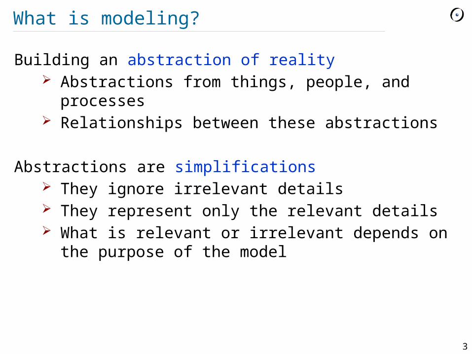
What is modeling?
Building an abstraction of reality Abstractions from things, people, and processes Relationships between these abstractions
Abstractions are simplifications They ignore irrelevant details They represent only the relevant details What is relevant or irrelevant depends on the
purpose of the model
4
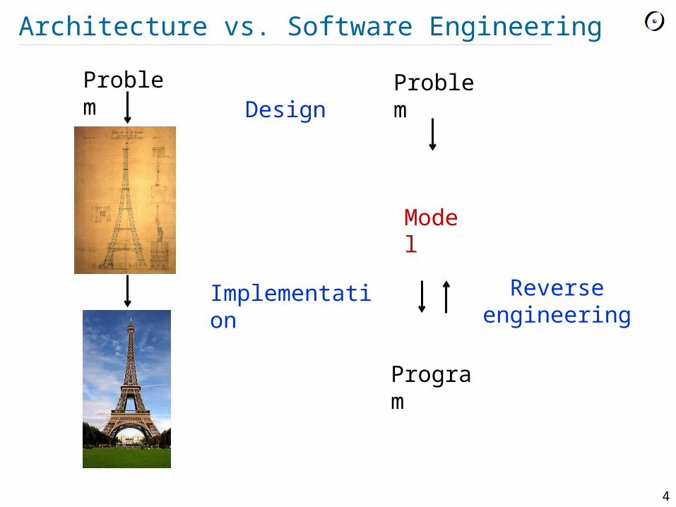
Architecture vs. Software Engineering
Problem Design
Implementation
Problem
Model
Program
Reverse engineering

5
The Unified Modeling Language, UML
Modeling language = language for describing models (mostly models of software)
Model in UML = graph vertices = entities edges = relations
Models can be represented in different formats (e.g. graphical, xmi)
Diagrams are graphical representation of parts of a model
6
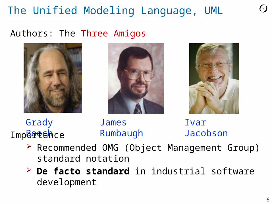
The Unified Modeling Language, UML
Authors: The Three Amigos
Importance Recommended OMG (Object Management
Group) standard notation De facto standard in industrial software
development
Grady Booch
James Rumbaugh
Ivar Jacobson
7
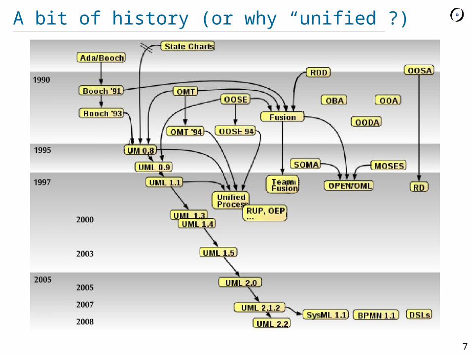
A bit of history (or why “unified”?)
8
Uses of UML
Specification: the language is supposed to be simple enough to be understood by the clients
Visualization: models can be represented graphically
plain text < text with pictures < comics Design: the language is supposed to be
precise enough to make code generation possible
Documentation: the language is supposed to be widespread enough to make your models understandable by other developers

9
What UML is not about?
Programming language this would bound the language to a specific
computing architecture however code generation is encouraged
Software development process however the authors had their own process
in mind: RUP (Rational Unified Process) CASE tool specification
however tools do exist: Sun, IBM Rose, Microsoft Visio, Borland Together e.t.c

10
Entities in UML
Structural Class – a description of a set of object
with common attributes and operations Interface – a set of operations (a
service), provided by a class or component
Actor – an external entity that interacts with the system
Use case – a description of a set of scenarios (sequences of events and actions) that produce a result, significant for some actor
Component – physically replaceable artifact that provides a certain set of interfaces
Node – a hardware resource
+operations()
-attributes
Name
Interface
Actor
Use case
Component
Node
11
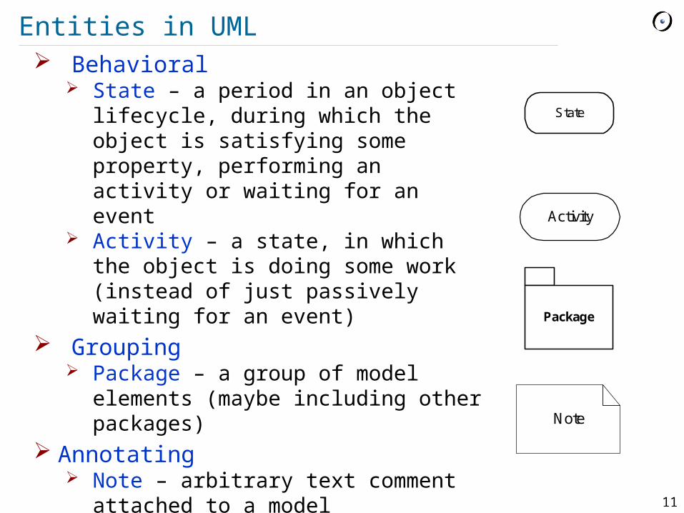
Entities in UML Behavioral
State – a period in an object lifecycle, during which the object is satisfying some property, performing an activity or waiting for an event
Activity – a state, in which the object is doing some work (instead of just passively waiting for an event)
Grouping Package – a group of model
elements (maybe including other packages)
Annotating Note – arbitrary text comment
attached to a model
State
Activity
Package
Note
12
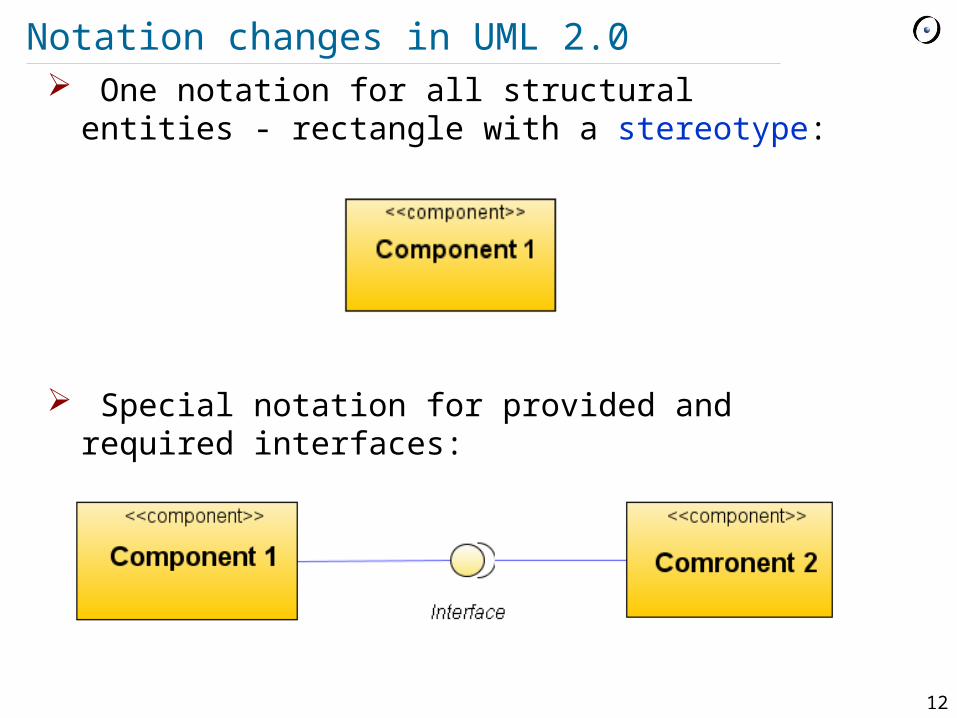
Notation changes in UML 2.0 One notation for all structural entities -
rectangle with a stereotype:
Special notation for provided and required
interfaces:

13
Relations in UML
Dependency – changing the independent entity may influence the dependent one
Association – entities are directly connected (e.g. aggregation)
Generalization – an entity is a special case of another entity, they satisfy the substitution principle
Implementation – an entity is an implementation of another entity (e.g. a class and an interface)
dependent
independent
entity1
entity2
descendant
ancestor
implementation
interface
14
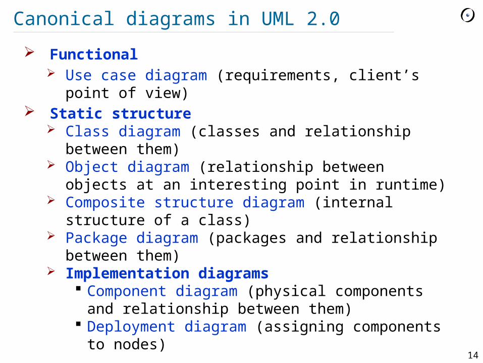
Canonical diagrams in UML 2.0
Functional Use case diagram (requirements, client’s point of
view) Static structure
Class diagram (classes and relationship between them)
Object diagram (relationship between objects at an interesting point in runtime)
Composite structure diagram (internal structure of a class)
Package diagram (packages and relationship between them)
Implementation diagrams Component diagram (physical components and
relationship between them) Deployment diagram (assigning components to
nodes)

15
Canonical diagrams in UML 2.0
Behavioral State diagram (object lifecycle) Activity diagram (= flowchart, algorithm
description) Interaction diagrams
Sequence diagram (message passing, ordered in time)
Communication diagram (message passing) Interaction overview diagram (= activity
diagram with interaction diagrams in nodes) Timing diagram (focus on timing constraints)
16
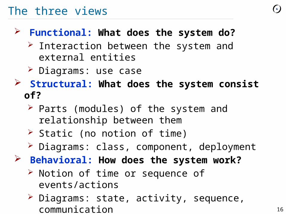
The three views
Functional: What does the system do? Interaction between the system and external
entities Diagrams: use case
Structural: What does the system consist of? Parts (modules) of the system and relationship
between them Static (no notion of time) Diagrams: class, component, deployment
Behavioral: How does the system work? Notion of time or sequence of events/actions Diagrams: state, activity, sequence,
communication
17
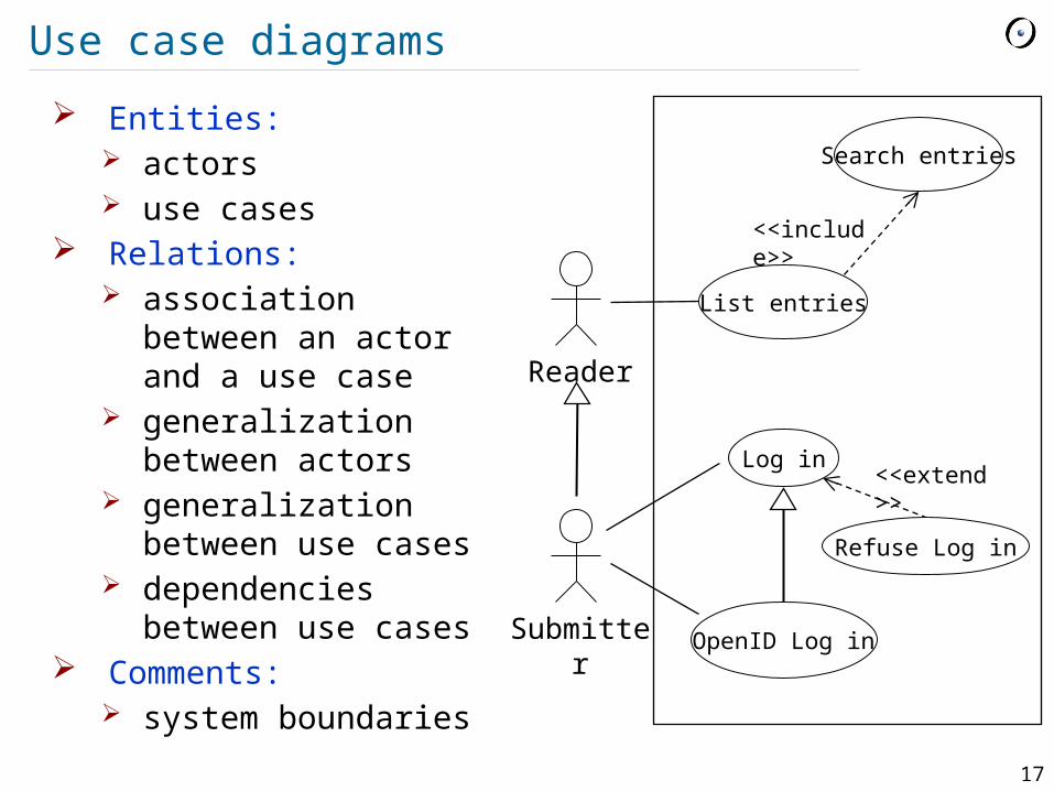
Use case diagrams
Entities: actors use cases
Relations: association between
an actor and a use case
generalization between actors
generalization between use cases
dependencies between use cases
Comments: system boundaries
Reader
List entries
Submitter
Log in
OpenID Log in
Search entries
<<include>>
Refuse Log in
<<extend>>
18
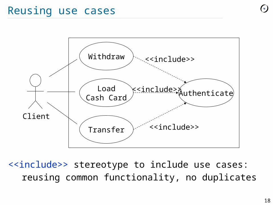
Reusing use cases
<<include>> stereotype to include use cases:reusing common functionality, no duplicates
Withdraw
Client
LoadCash Card
Transfer
Authenticate
<<include>>
<<include>>
<<include>>
19
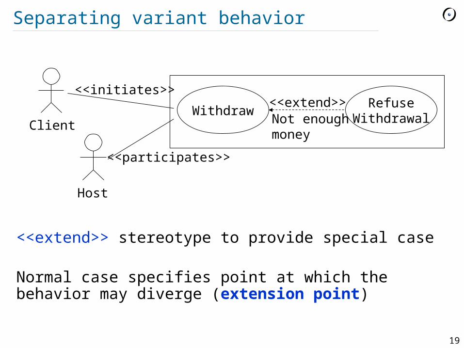
Separating variant behavior
<<extend>> stereotype to provide special case
Normal case specifies point at which the behavior may diverge (extension point)
WithdrawClient
RefuseWithdrawal
<<extend>>Not enoughmoney
Host
<<initiates>>
<<participates>>
20
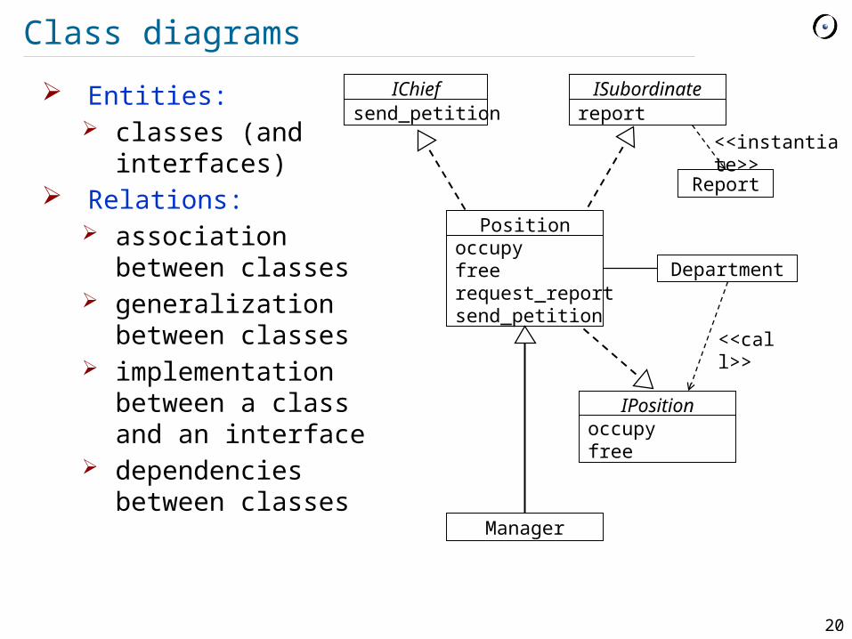
Class diagrams
Entities: classes (and
interfaces) Relations:
association between classes
generalization between classes
implementation between a class and an interface
dependencies between classes
Positionoccupyfreerequest_reportsend_petition
IChiefsend_petition
ISubordinatereport
IPositionoccupyfree
Department
Report
Manager
<<instantiate>>
<<call>>
21
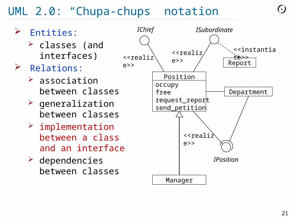
UML 2.0: “Chupa-chups” notation
Entities: classes (and
interfaces) Relations:
association between classes
generalization between classes
implementation between a class and an interface
dependencies between classes
Positionoccupyfreerequest_reportsend_petition
Department
Report
Manager
<<instantiate>>
IChief ISubordinate
<<realize>>
<<realize>>
IPosition
<<realize>>

22
Associations
Most widely used relation on class diagrams In general means that classes know about each
other - their objects can send each other messages (call operations, read attributes)
Special cases: Class A has an attribute of type B Class A creates instances of B Class A receives a message with argument of
type B Mostly are binary, but can be N-ary Can have different adornments that express
additional information
23
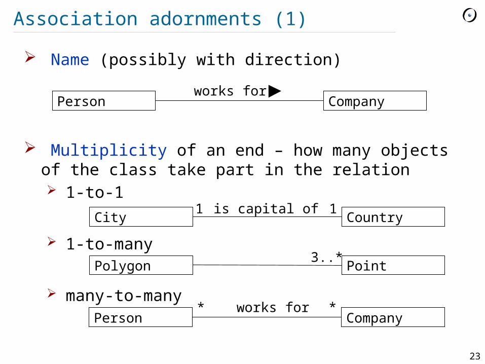
Association adornments (1)
Name (possibly with direction)
Multiplicity of an end – how many objects of the class take part in the relation 1-to-1
1-to-many
many-to-many
Person Companyworks for
City Country1 1is capital of
Polygon Point3..*
Person Companyworks for* *

24
Association adornments (2)
Aggregation – part-of relation between objects an object can be part of multiple objects part can be created and destroyed
independently of the aggregate
Composition – strong aggregation an object can only be part of a single object exists only together with the aggregate
Curriculum Course*
TicketMachine ZoneButton3

25
Association adornments (3)
Role of an end: name + interface
Navigability of an end – whether the objects at this
end can be accessed through this association
Position
subordination
*
0..1chief: IChief
subordinate: ISubordinate
Password Hashcode1 1

26
Association adornments (4)
Ordering of an end – whether the objects at this end are ordered
Changeability of an end – whether the set of objects at this end can be changed after creation
Qualifier of an end – is an attribute that allows retrieving one object from the set at this end
Polygon Point3..*
{ordered}{frozen, ordered}number
0..1
27
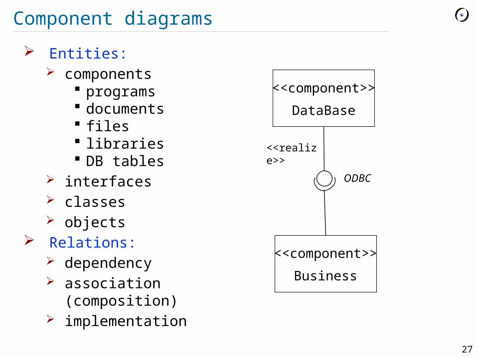
Component diagrams
Entities: components
programs documents files libraries DB tables
interfaces classes objects
Relations: dependency association
(composition) implementation
<<component>>
DataBase
<<component>>
Business
ODBC
<<realize>>
28
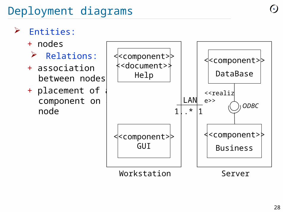
Deployment diagrams
Entities: + nodes Relations:
+ association between nodes
+ placement of a component on a node
<<component>>
DataBase
<<component>>
Business
ODBC
<<realize>>
<<component>><<document>>
Help
<<component>>GUI
11..*LAN
Workstation Server

29
State diagrams
Entities: states: name, activity, entry/exit action
Relations: transitions between states: event, condition,
action
State 1
do / activityentry / actionexit / action
State 2
do / activityentry / actionexit / action
event (arg) [ condition ] / action
30
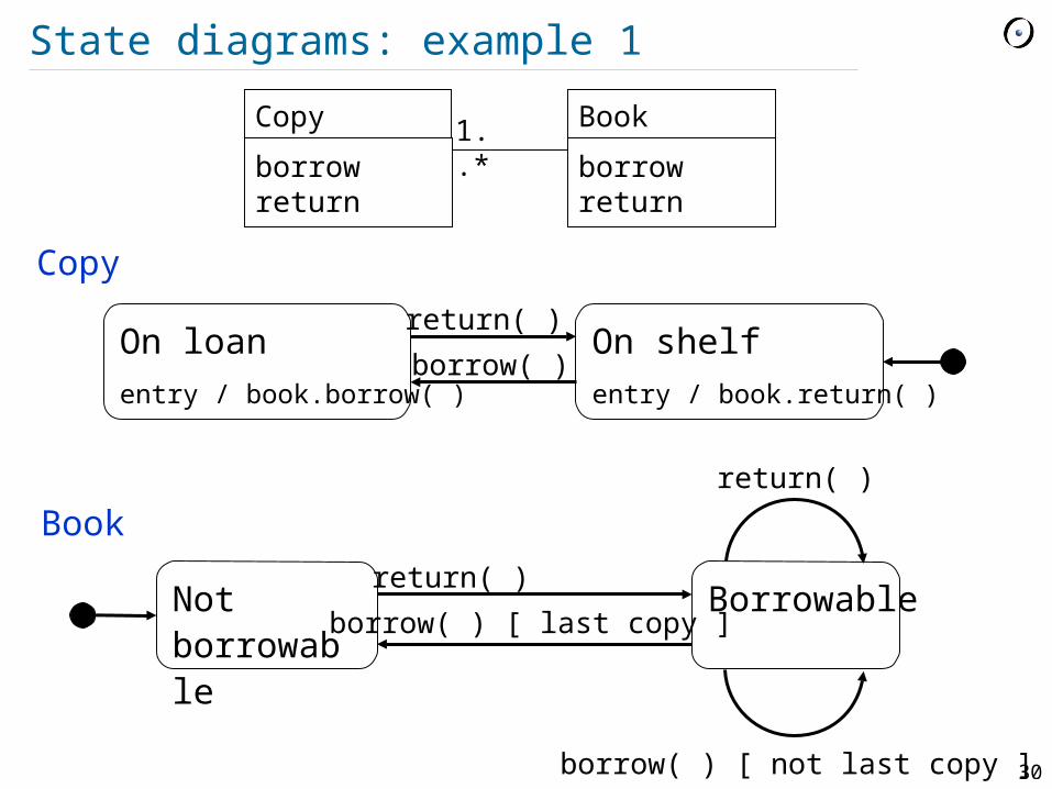
State diagrams: example 1
On loanentry / book.borrow( )
On shelfentry / book.return( )
return( )
borrow( )
Copy 1..*
Book
borrowreturn
borrowreturn
Not borrowable
Borrowablereturn( )
borrow( ) [ last copy ]
return( )
borrow( ) [ not last copy ]
Copy
Book

31
State diagrams: example 2 (composite state)
Off
On
Working
Blinking
Red Yellow
Yellow Green
Red Green
TurnOn
TurnOff
SwitchOnSwitchOff
after 3 sec
after 45 secafter 5 sec
after 30 sec
TrafficLight

32
Activity diagrams
Entities: activities
Relations: transitions
between activities
Sugar decisions forks swimlanes
Request service
Pay
Take order
Fill order
Deliver order
Collect order
Customer Sales Stockroom
33
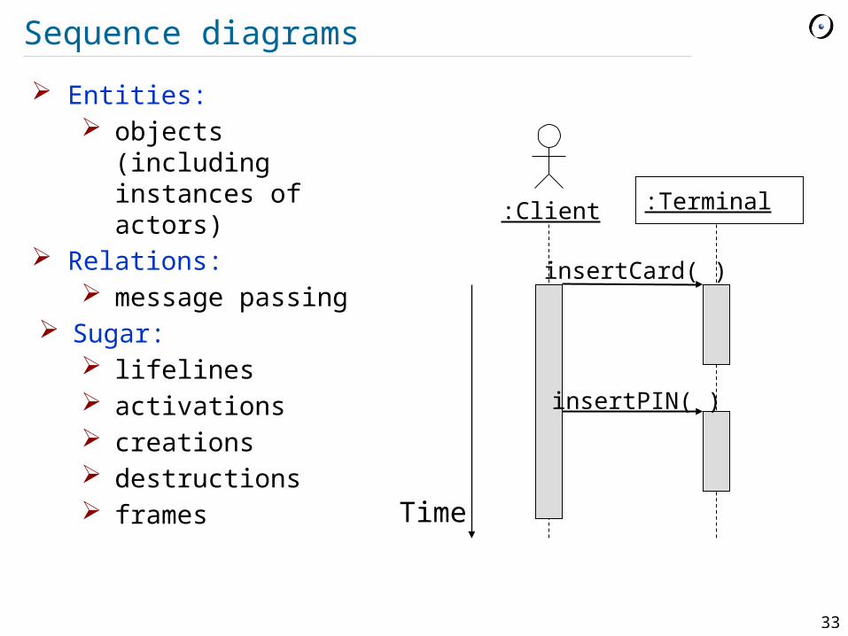
Sequence diagrams
:Client :Terminal
insertCard( )
insertPIN( )
Time
Entities: objects (including
instances of actors) Relations:
message passing Sugar:
lifelines activations creations destructions frames
34
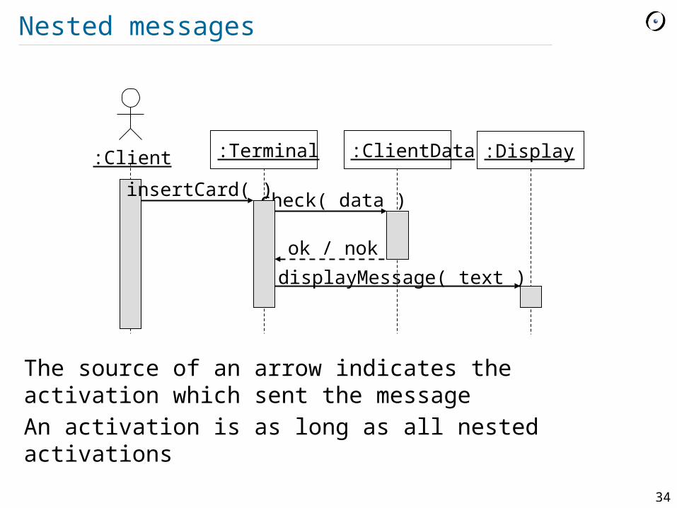
Nested messages
The source of an arrow indicates the activation which sent the messageAn activation is as long as all nested activations
:Client :Terminal
insertCard( )
:ClientData
check( data )
ok / nok
:Display
displayMessage( text )
35
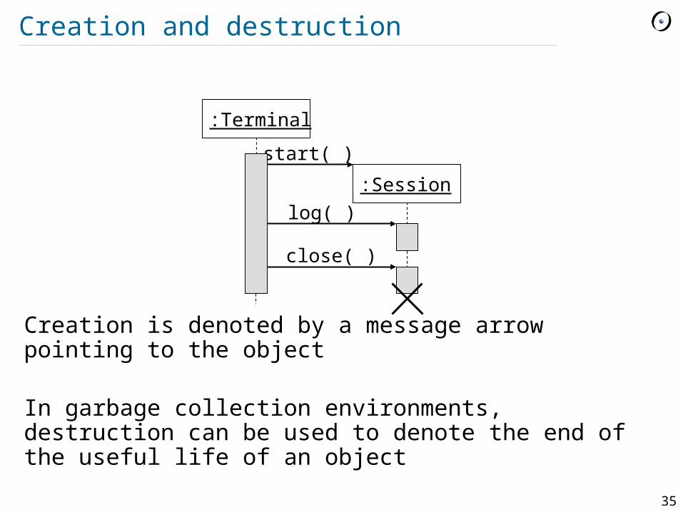
Creation and destruction
Creation is denoted by a message arrow pointing to the object
In garbage collection environments, destruction can be used to denote the end of the useful life of an object
:Terminal
:Session
start( )
log( )
close( )
36
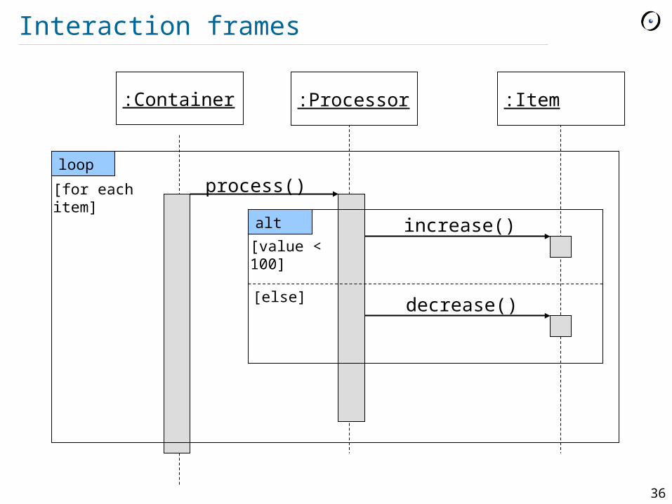
Interaction frames
:Item:Container :Processor
process()
increase()
loop
[for each item]
decrease()
alt
[value < 100]
[else]
37
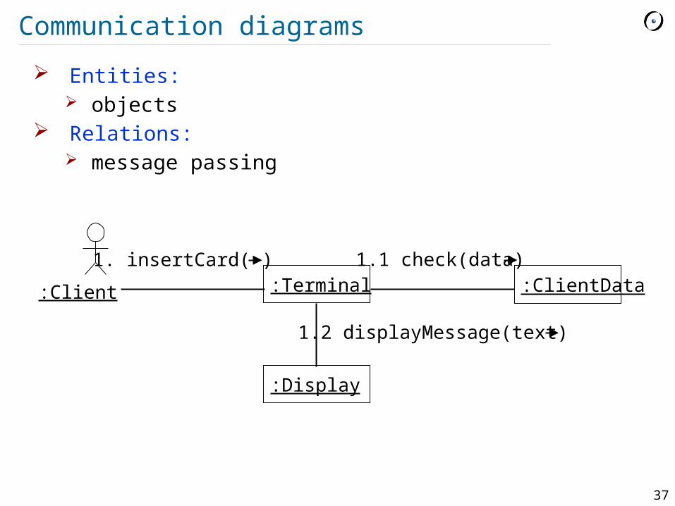
Communication diagrams
Entities: objects
Relations: message passing
:Client :Terminal :ClientData
:Display
1. insertCard( ) 1.1 check(data)
1.2 displayMessage(text)
38
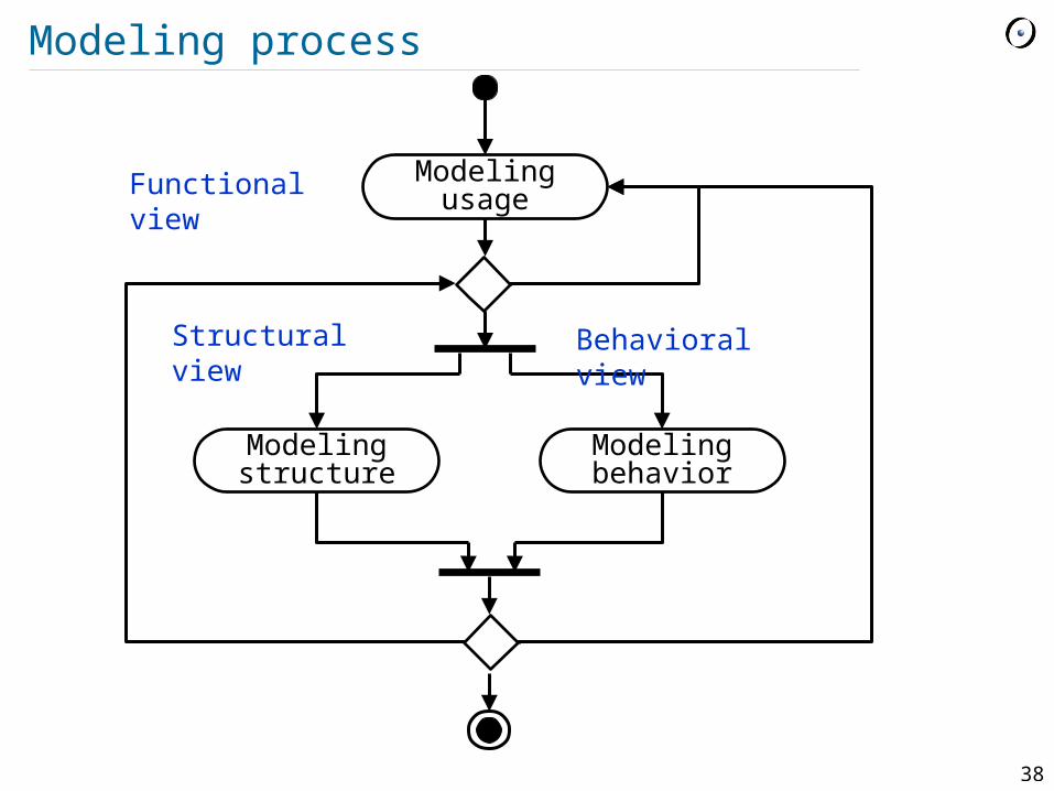
Modeling process
Modeling usage
Modeling structure
Modeling behavior
Functional view
Structural view Behavioral view
39
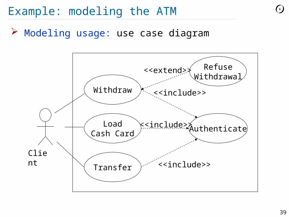
Example: modeling the ATM
Withdraw
Client
LoadCash Card
Transfer
Authenticate
<<include>>
<<include>>
<<include>>
RefuseWithdrawal
<<extend>>
Modeling usage: use case diagram
40
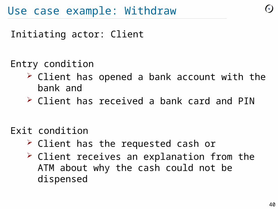
Use case example: Withdraw
Initiating actor: Client
Entry condition Client has opened a bank account with the bank
and Client has received a bank card and PIN
Exit condition Client has the requested cash or Client receives an explanation from the ATM
about why the cash could not be dispensed
41
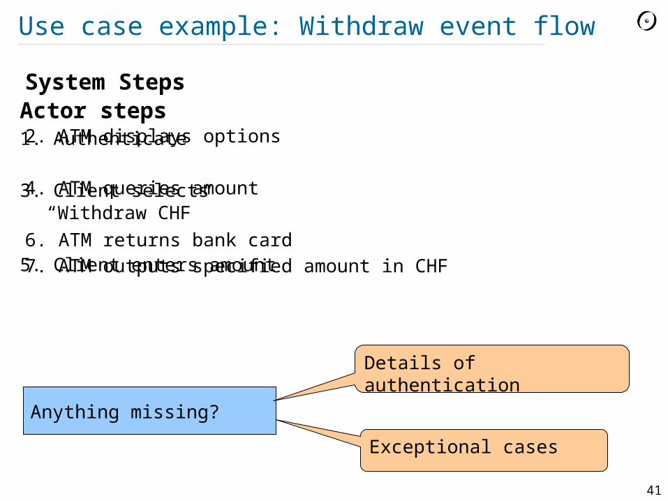
Use case example: Withdraw event flow
Actor steps1. Authenticate
3. Client selects “Withdraw CHF”
5. Client enters amount
System Steps
2. ATM displays options
4. ATM queries amount
6. ATM returns bank card7. ATM outputs specified amount in CHF
Anything missing?
Exceptional cases
Details of authentication
42
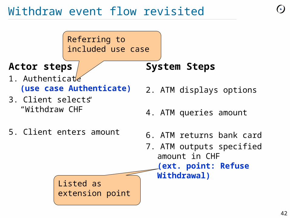
Withdraw event flow revisited
Actor steps1. Authenticate
(use case Authenticate) 3. Client selects “Withdraw
CHF”
5. Client enters amount
System Steps
2. ATM displays options
4. ATM queries amount
6. ATM returns bank card7. ATM outputs specified amount
in CHF(ext. point: Refuse Withdrawal)
Listed as extension point
Referring to included use case
43
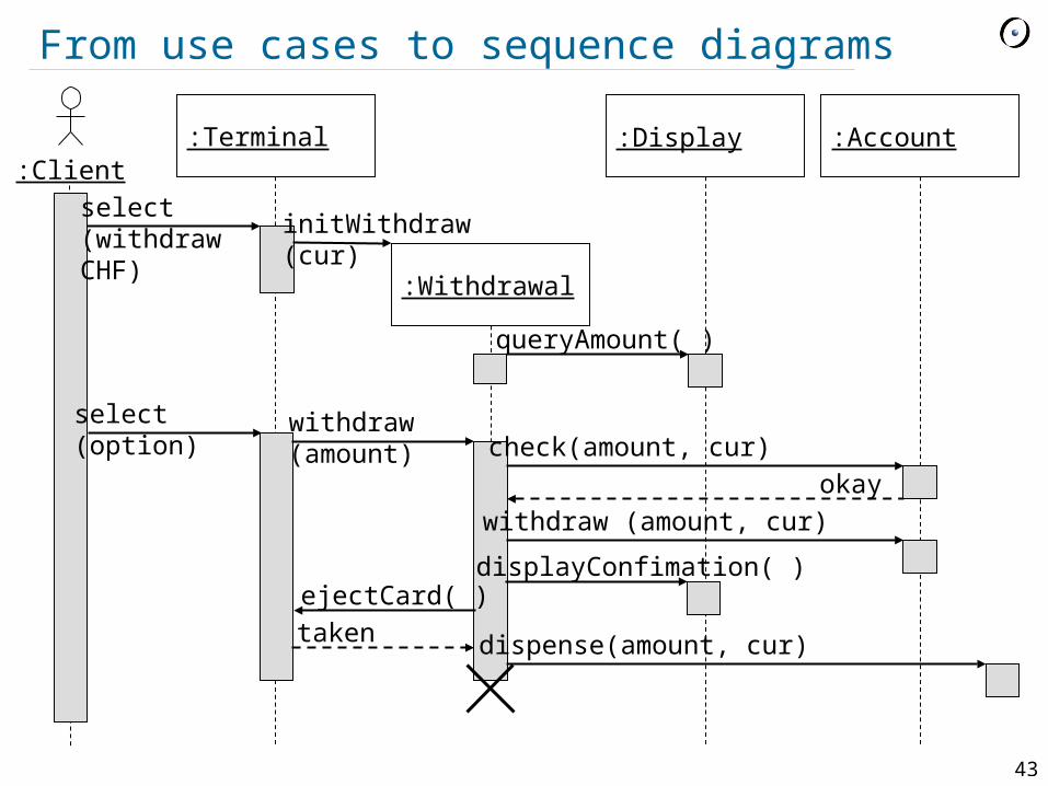
:Account:Client
:Terminal
select(withdrawCHF)
:Withdrawal
initWithdraw(cur)
:Display
queryAmount( )
select(option)
withdraw(amount)
withdraw (amount, cur)
displayConfimation( )ejectCard( )
taken
check(amount, cur)okay
dispense(amount, cur)
From use cases to sequence diagrams

44
... and futher to class diagrams
Add a class for each object on the diagram For each object that receives an event add a public
operation in the associated class
Identify additional classes (e.g. for message arguments, messages with no receivers)
Problem text analysis may help (nouns may correspond to classes, verbs – to operations)
:Account
check (amount, cur)
withdraw (amount, cur)okay
Account
check (int, Currency): boolean withdraw (int, Currency)
45
Practical tips
Create component and deployment diagrams only for large, distributed systems
Create state diagrams only for classes with complex, interesting behavior (usually classes representing entities from the problem domain or performing control)
Create activity diagrams for complex algorithms and business processes (not for every operation)
Create sequence and communication diagrams for nontrivial collaborations and protocols (not for every scenario)
Don’t put too much information on a diagram Choose the level of abstraction and maintain it