Embed Size (px)
Citation preview
Challenges and
Solutions for GPS
Receiver Test
Presenter: Mirin Lew
January 28, 2010
© 2010 Agilent Technologies
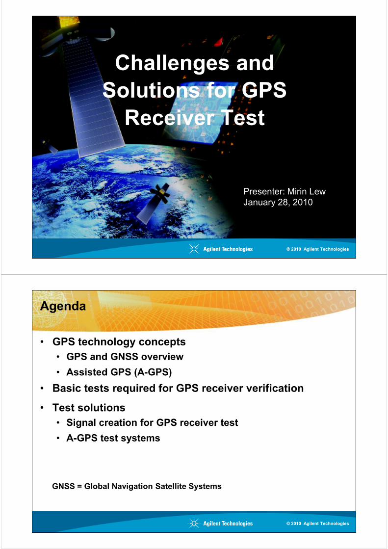
Agenda
• GPS technology concepts
• GPS and GNSS overview
• Assisted GPS (A-GPS)
• Basic tests required for GPS receiver verification
• Test solutions• Test solutions
• Signal creation for GPS receiver test
• A-GPS test systems
GNSS = Global Navigation Satellite Systems
© 2010 Agilent Technologies

GPS and GNSS Overview
GPS: Global Positioning System
• System owned and operated by the U.S. government
• Civilian service freely available to users worldwide
• Military service available to selected agencies onlyagencies only
GNSS: Global Navigation Satellite System
• General term for any satellite-based navigation system
• Includes multiple systems worldwide
© 2010 Agilent Technologies
Global Navigation Satellite Systems (GNSS)
Galileo
– Joint effort of European Community and European Space Agency
– 2 test satellites in orbit, contracts awarded for first 14 satellites, up to 32 satellites operational by 2014
– Interoperability agreement signed with GPS
– 4 services (open service, paid commercial service, safety of life service, public regulated service) as compared to 2 GPS services (public and private)
Global Orbiting Navigation Satellite System (GLONASS)
– Russian system first launched by Soviet Union in 1982
– Became non-functional for most applications in the 1990’s
– Currently being restored, 22 satellites in orbit as of Dec. 2009
– Particularly good coverage over upper latitudes (Northern Europe)
Compass (Beidou-2)
– Chinese system
– 3 satellites are up, 12 satellites by 2012 to provide regional service
– Eventually 30 satellites
© 2010 Agilent Technologies
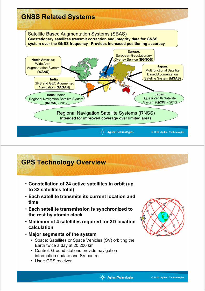
GNSS Related Systems
Satellite Based Augmentation Systems (SBAS)Geostationary satellites transmit correction and integrity data for GNSS
system over the GNSS frequency. Provides increased positioning accuracy.
North America:
Wide Area
Augmentation System
(WAAS)
Europe:
European Geostationary
Overlay Service (EGNOS)
Japan:
Multifunctional Satellite
Based Augmentation
Regional Navigation Satellite Systems (RNSS)Intended for improved coverage over limited areas
(WAAS)Based Augmentation
Satellite System (MSAS)
Japan:
Quazi Zenith Satellite
System (QZSS) - 2013
India: Indian
Regional Navigation Satellite System
(INRSS) - 2012
India:
GPS and GEO Augmented
Navigation (GAGAN)
© 2010 Agilent Technologies
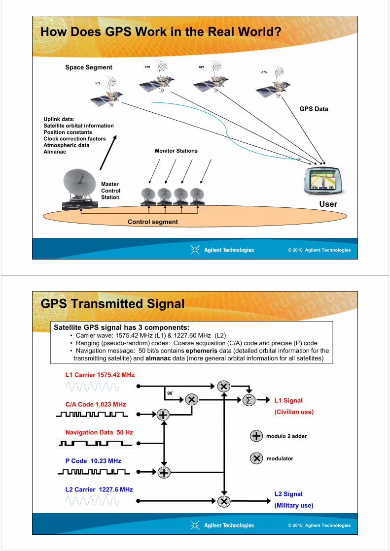
GPS Technology Overview
• Constellation of 24 active satellites in orbit (up to 32 satellites total)
• Each satellite transmits its current location and time
• Each satellite transmission is synchronized to the rest by atomic clock
• Minimum of 4 satellites required for 3D location calculation
• Major segments of the system
• Space: Satellites or Space Vehicles (SV) orbiting the
Earth twice a day at 20,200 km
• Control: Ground stations provide navigation
information update and SV control
• User: GPS receiver
© 2010 Agilent Technologies
How Does GPS Work in the Real World?
Space Segment
Uplink data:Satellite orbital information
Position constantsClock correction factors
GPS Data
Monitor Stations
MasterControl
Station
User
Clock correction factorsAtmospheric data
Almanac
Control segment
© 2010 Agilent Technologies
GPS Transmitted Signal
L1 Carrier 1575.42 MHz
C/A Code 1.023 MHzL1 Signal
(Civilian use)+Σ
90˚
Satellite GPS signal has 3 components:• Carrier wave: 1575.42 MHz (L1) & 1227.60 MHz (L2)
• Ranging (pseudo-random) codes: Coarse acquisition (C/A) code and precise (P) code
• Navigation message: 50 bit/s contains ephemeris data (detailed orbital information for the
transmitting satellite) and almanac data (more general orbital information for all satellites)
Navigation Data 50 Hz
P Code 10.23 MHz
L2 Carrier 1227.6 MHz
(Civilian use)
L2 Signal
(Military use)
modulo 2 adder
modulator
+
+
+
© 2010 Agilent Technologies
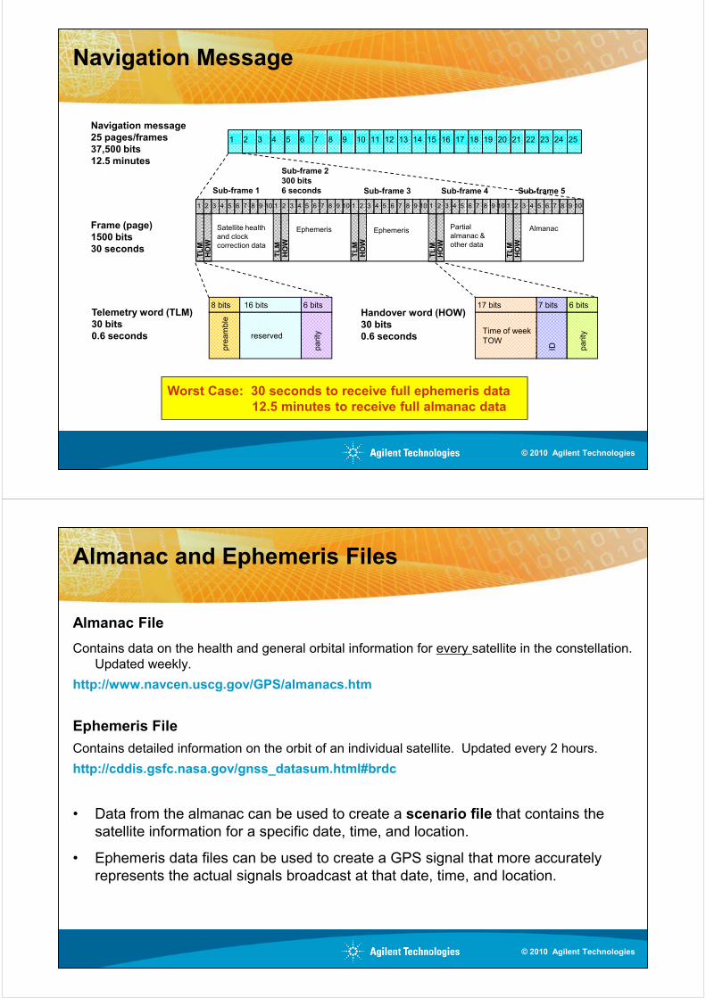
Navigation Message
1 2 3 4 5 6 7 8 9 10 11 12 13 14 15 16 17 18 19 20 21 22 23 24 25
Navigation message
25 pages/frames37,500 bits12.5 minutes
Frame (page)
1500 bits30 seconds
Sub-frame 2
300 bits
6 secondsSub-frame 1 Sub-frame 3 Sub-frame 4 Sub-frame 5TLM
HOW
1 2 3 4 5 6 7 8 9 10
Satellite health
and clock
correction data
Ephemeris Ephemeris Partial
almanac &
other data
Almanac
TLM
HOW
1 2 3 4 5 6 7 8 9 10
TLM
HOW
1 2 3 4 5 6 7 8 9 10
TLM
HOW
1 2 3 4 5 6 7 8 9 10
TLM
HOW
1 2 3 4 5 6 7 8 9 10
8 bits
pre
am
ble
16 bits
reserved
6 bits
parity
7 bits
ID
17 bits
Time of week
TOW
6 bits
parity
30 seconds
Telemetry word (TLM)30 bits0.6 seconds
Handover word (HOW)30 bits0.6 seconds
TLM
HOW correction data
TLM
HOW
TLM
HOW
TLM
HOW
TLM
HOW
Worst Case: 30 seconds to receive full ephemeris data
12.5 minutes to receive full almanac data
© 2010 Agilent Technologies
Almanac and Ephemeris Files
Almanac File
Contains data on the health and general orbital information for every satellite in the constellation.
Updated weekly.
http://www.navcen.uscg.gov/GPS/almanacs.htm
Ephemeris File
Contains detailed information on the orbit of an individual satellite. Updated every 2 hours.Contains detailed information on the orbit of an individual satellite. Updated every 2 hours.
http://cddis.gsfc.nasa.gov/gnss_datasum.html#brdc
• Data from the almanac can be used to create a scenario file that contains the
satellite information for a specific date, time, and location.
• Ephemeris data files can be used to create a GPS signal that more accurately
represents the actual signals broadcast at that date, time, and location.
© 2010 Agilent Technologies
Agenda
• GPS technology concepts
• GPS and GNSS overview
• Assisted GPS (A-GPS)
• Basic tests required for GPS receiver verification
• Test solutions
• Signal creation for GPS receiver test
• A-GPS test systems
GNSS = Global Navigation Satellite Systems
© 2010 Agilent Technologies
Assisted GPS (A-GPS)
• Technique for cellular network to assist mobile phone’s GPS receiver to lock to
satellites and achieve location fix more quickly
– Fulfills U.S. FCC’s E911 directive which mandated fast and accurate location of mobile
phones by emergency services
– Needed due to low GPS signal levels that may be seen by mobile phones when indoors or
in areas without direct view of sufficient satellites
– Allows mobile phone’s GPS receiver to acquire location fix much more quickly
• Base station provides “assistance data” to mobile phones. Data includes:• Base station provides “assistance data” to mobile phones. Data includes:
– Navigation: precise satellite orbital information
– Almanac: coarse orbital information
– Time of Week: GPS time
– Ionosphere: single frequency (L1) correction factors
– Reference location: initial estimate of location
– Acquisition assistance: data to aid in locating or tracking satellites
– Real-time integrity: list of bad satellites
– UTC model: leap second time correction for GPS time
© 2010 Agilent Technologies

How Does A-GPS Work in the Real World?
Space Segment
Uplink data:Satellite ephemeris
Position constantsClock correction factors
Monitor Stations
MasterControl
Station
User
Clock correction factorsAtmospheric data
Almanac
Control segment
GPS AssistanceServer
Cellular Network
Network Downlink:Coarse TimeEphemeris Data
Coarse Location(100m accuracy)Almanac
© 2010 Agilent Technologies
A-GPS Operation
• Assistance Data Transportation
• Control plane: Uses dedicated messaging on network control channels
• User plane: Uses existing standard Internet protocol (IP) based data
connections; also called Secure User Plane Location (SUPL)
• A-GPS Modes
• Mobile station/user equipment (MS/UE) Assisted (older method)• Mobile station/user equipment (MS/UE) Assisted (older method)
– MS/UE supplies GPS measurements to network
– Network combines with assistance server data, calculates and transmits
location back to mobile
– Typically used with control plane
• MS/UE Based (newer method)
– MS/UE uses assistance data to calculate location
– Transmits location back to BS
– Used with user plane (less network dependent)
© 2010 Agilent Technologies
Agenda
• GPS technology concepts
• GPS and GNSS overview
• Assisted GPS (A-GPS)
• Basic tests required for GPS receiver verification
• Test solutions
• Signal creation for GPS receiver test
• A-GPS test systems
© 2010 Agilent Technologies
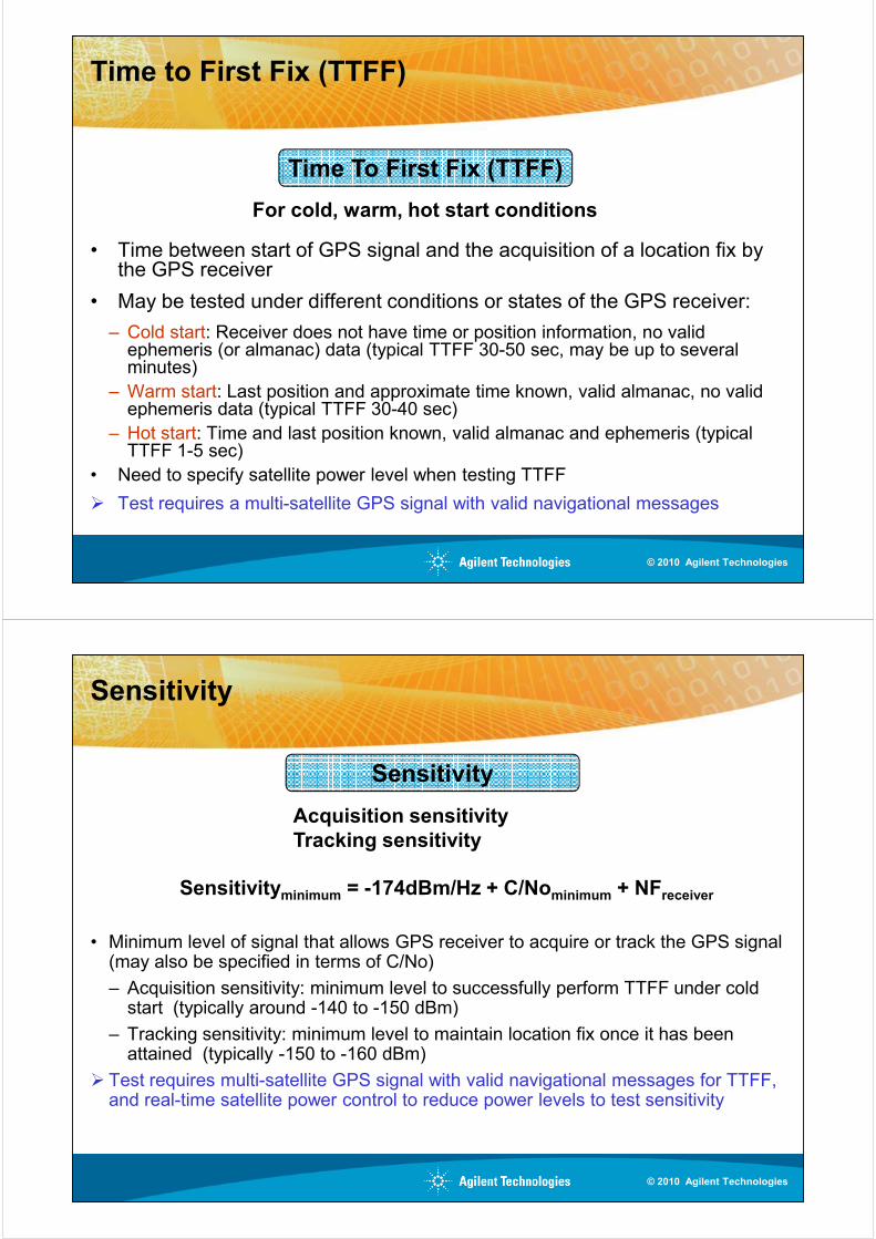
Typical Tests for GPS Receiver Verification
Time To First Fix (TTFF)
Sensitivity
Cold, warm, hot start conditions
Acquisition sensitivity
Location Accuracy
Acquisition sensitivity
Tracking sensitivity
Absolute and relative accuracy
Moving GPS receiver accuracy
Satellite tracking accuracy
© 2010 Agilent Technologies
Time to First Fix (TTFF)
• Time between start of GPS signal and the acquisition of a location fix by the GPS receiver
• May be tested under different conditions or states of the GPS receiver:
Time To First Fix (TTFF)
For cold, warm, hot start conditions
• May be tested under different conditions or states of the GPS receiver:
– Cold start: Receiver does not have time or position information, no valid ephemeris (or almanac) data (typical TTFF 30-50 sec, may be up to several minutes)
– Warm start: Last position and approximate time known, valid almanac, no valid ephemeris data (typical TTFF 30-40 sec)
– Hot start: Time and last position known, valid almanac and ephemeris (typical TTFF 1-5 sec)
• Need to specify satellite power level when testing TTFF
� Test requires a multi-satellite GPS signal with valid navigational messages
© 2010 Agilent Technologies
Sensitivity
Sensitivityminimum = -174dBm/Hz + C/Nominimum + NFreceiver
Sensitivity
Acquisition sensitivityTracking sensitivity
• Minimum level of signal that allows GPS receiver to acquire or track the GPS signal (may also be specified in terms of C/No)
– Acquisition sensitivity: minimum level to successfully perform TTFF under cold start (typically around -140 to -150 dBm)
– Tracking sensitivity: minimum level to maintain location fix once it has been attained (typically -150 to -160 dBm)
� Test requires multi-satellite GPS signal with valid navigational messages for TTFF, and real-time satellite power control to reduce power levels to test sensitivity
© 2010 Agilent Technologies
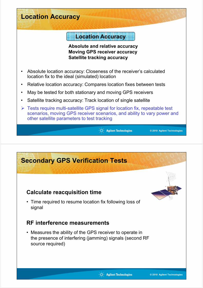
Location Accuracy
• Absolute location accuracy: Closeness of the receiver’s calculated
Location Accuracy
Absolute and relative accuracyMoving GPS receiver accuracySatellite tracking accuracy
• Absolute location accuracy: Closeness of the receiver’s calculated location fix to the ideal (simulated) location
• Relative location accuracy: Compares location fixes between tests
• May be tested for both stationary and moving GPS receivers
• Satellite tracking accuracy: Track location of single satellite
� Tests require multi-satellite GPS signal for location fix, repeatable test scenarios, moving GPS receiver scenarios, and ability to vary power and other satellite parameters to test tracking
© 2010 Agilent Technologies
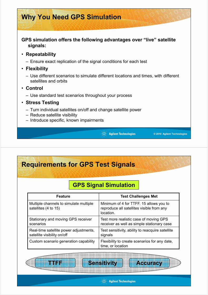
Secondary GPS Verification Tests
Calculate reacquisition time
• Time required to resume location fix following loss of
signal
RF interference measurements
• Measures the ability of the GPS receiver to operate in
the presence of interfering (jamming) signals (second RF
source required)
© 2010 Agilent Technologies
Why You Need GPS Simulation
GPS simulation offers the following advantages over “live” satellite signals:
• Repeatability
– Ensure exact replication of the signal conditions for each test
• Flexibility
– Use different scenarios to simulate different locations and times, with different – Use different scenarios to simulate different locations and times, with different
satellites and orbits
• Control
– Use standard test scenarios throughout your process
• Stress Testing
– Turn individual satellites on/off and change satellite power
– Reduce satellite visibility
– Introduce specific, known impairments
© 2010 Agilent Technologies
Requirements for GPS Test Signals
GPS Signal Simulation
Feature Test Challenges Met
Multiple channels to simulate multiple
satellites (4 to 15)
Minimum of 4 for TTFF. 15 allows you to
reproduce all satellites visible from any
location.
Stationary and moving GPS receiver Test more realistic case of moving GPS
TTFF AccuracySensitivity
Stationary and moving GPS receiver
scenarios
Test more realistic case of moving GPS
receiver as well as simple stationary case
Real-time satellite power adjustments,
satellite visibility on/off
Test sensitivity, ability to reacquire satellite
signals
Custom scenario generation capability Flexibility to create scenarios for any date,
time, or location
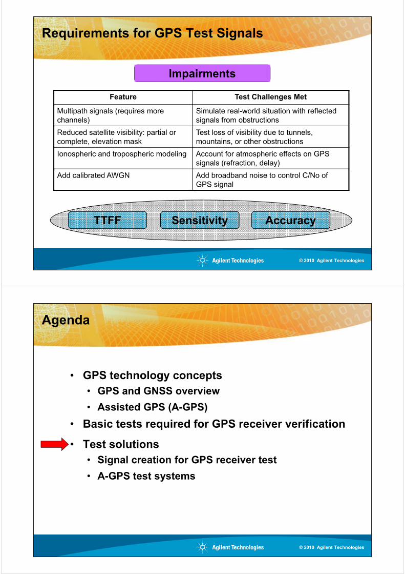
Requirements for GPS Test Signals
Impairments
Feature Test Challenges Met
Multipath signals (requires more
channels)
Simulate real-world situation with reflected
signals from obstructions
Reduced satellite visibility: partial or
complete, elevation mask
Test loss of visibility due to tunnels,
mountains, or other obstructions
TTFF AccuracySensitivity
complete, elevation mask mountains, or other obstructions
Ionospheric and tropospheric modeling Account for atmospheric effects on GPS
signals (refraction, delay)
Add calibrated AWGN Add broadband noise to control C/No of
GPS signal
© 2010 Agilent Technologies
Agenda
• GPS technology concepts
• GPS and GNSS overview
• Assisted GPS (A-GPS)
• Basic tests required for GPS receiver verification
• Test solutions
• Signal creation for GPS receiver test
• A-GPS test systems
© 2010 Agilent Technologies
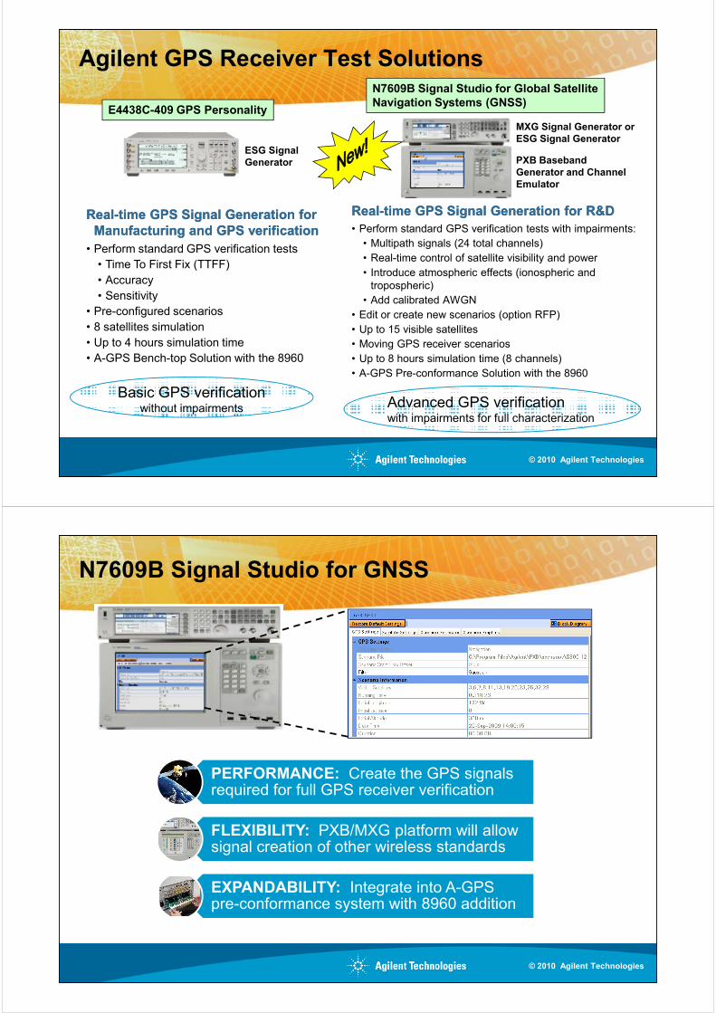
Agilent GPS Receiver Test Solutions
RealReal--time GPS Signal Generation for R&Dtime GPS Signal Generation for R&D
• Perform standard GPS verification tests with impairments:
• Multipath signals (24 total channels)
• Real-time control of satellite visibility and power
PXB Baseband
Generator and Channel Emulator
MXG Signal Generator or ESG Signal Generator
RealReal--time GPS Signal Generation for time GPS Signal Generation for
Manufacturing and GPS verificationManufacturing and GPS verification
• Perform standard GPS verification tests
ESG Signal Generator
E4438C-409 GPS Personality
N7609B Signal Studio for Global SatelliteNavigation Systems (GNSS)
• Real-time control of satellite visibility and power
• Introduce atmospheric effects (ionospheric and
tropospheric)
• Add calibrated AWGN
• Edit or create new scenarios (option RFP)
• Up to 15 visible satellites
• Moving GPS receiver scenarios
• Up to 8 hours simulation time (8 channels)
• A-GPS Pre-conformance Solution with the 8960
• Perform standard GPS verification tests
• Time To First Fix (TTFF)
• Accuracy
• Sensitivity
• Pre-configured scenarios
• 8 satellites simulation
• Up to 4 hours simulation time
• A-GPS Bench-top Solution with the 8960
Basic GPS verificationwithout impairments Advanced GPS verification
with impairments for full characterization
© 2010 Agilent Technologies
N7609B Signal Studio for GNSS
PERFORMANCE: Create the GPS signals required for full GPS receiver verification
FLEXIBILITY: PXB/MXG platform will allow signal creation of other wireless standards
EXPANDABILITY: Integrate into A-GPS pre-conformance system with 8960 addition
© 2010 Agilent Technologies
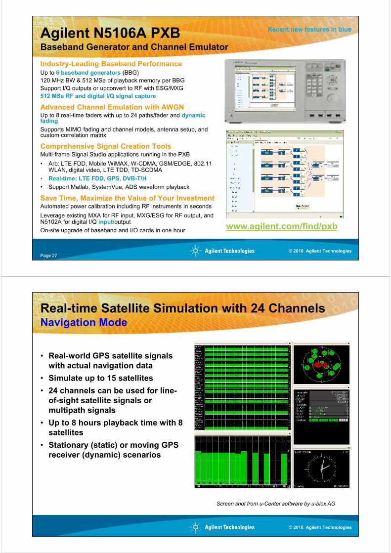
Agilent N5106A PXBBaseband Generator and Channel Emulator
Industry-Leading Baseband PerformanceUp to 6 baseband generators (BBG)
120 MHz BW & 512 MSa of playback memory per BBG
Support I/Q outputs or upconvert to RF with ESG/MXG
512 MSa RF and digital I/Q signal capture
Advanced Channel Emulation with AWGNUp to 8 real-time faders with up to 24 paths/fader and dynamic fading
Supports MIMO fading and channel models, antenna setup, and custom correlation matrix
Recent new features in blue
custom correlation matrix
Comprehensive Signal Creation ToolsMulti-frame Signal Studio applications running in the PXB
• Arb: LTE FDD, Mobile WiMAX, W-CDMA, GSM/EDGE, 802.11 WLAN, digital video, LTE TDD, TD-SCDMA
• Real-time: LTE FDD, GPS, DVB-T/H
• Support Matlab, SystemVue, ADS waveform playback
Save Time, Maximize the Value of Your InvestmentAutomated power calibration including RF instruments in seconds
Leverage existing MXA for RF input, MXG/ESG for RF output, and N5102A for digital I/Q input/output
On-site upgrade of baseband and I/O cards in one hourwww.agilent.com/find/pxb
Page 27© 2010 Agilent Technologies
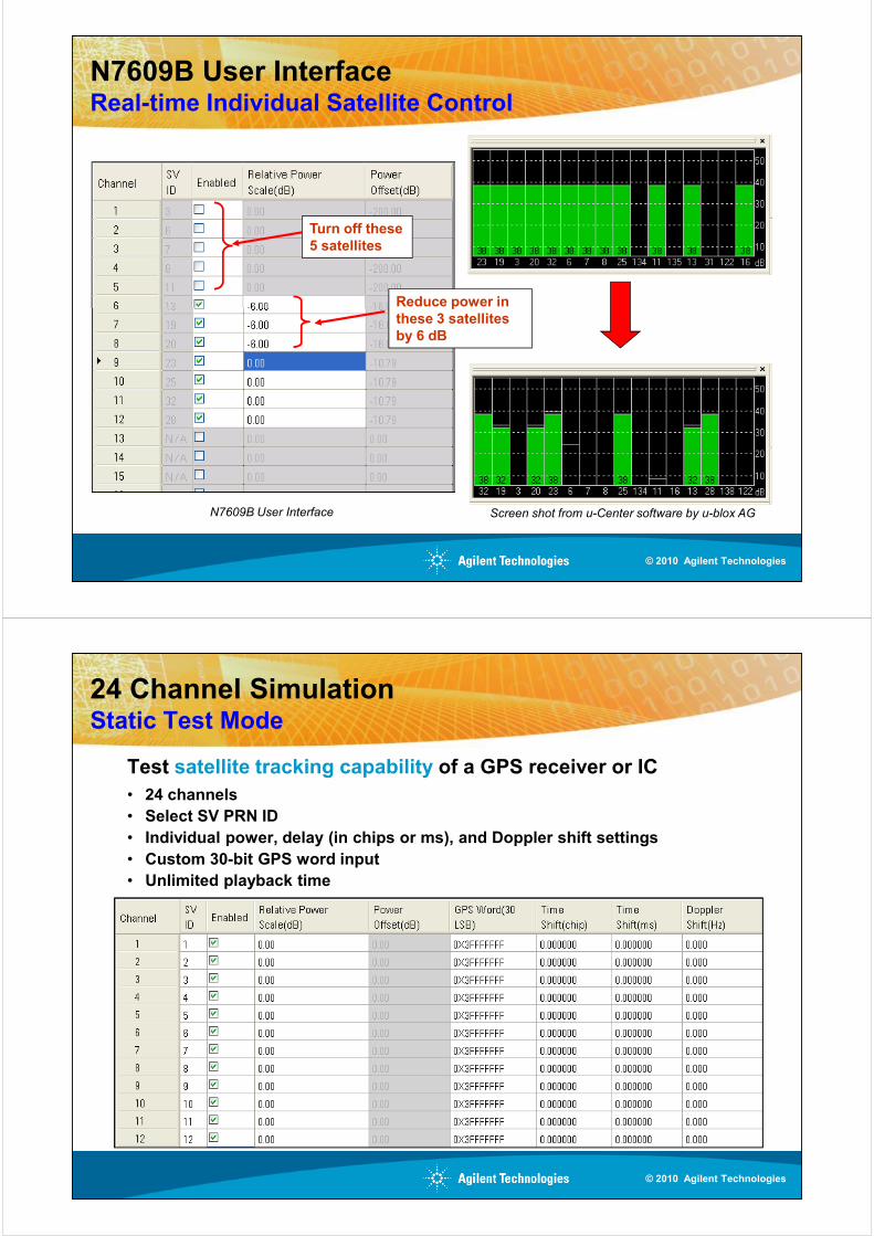
Real-time Satellite Simulation with 24 ChannelsNavigation Mode
• Real-world GPS satellite signals
with actual navigation data
• Simulate up to 15 satellites
• 24 channels can be used for line-
of-sight satellite signals or
multipath signalsmultipath signals
• Up to 8 hours playback time with 8
satellites
• Stationary (static) or moving GPS
receiver (dynamic) scenarios
Screen shot from u-Center software by u-blox AG
© 2010 Agilent Technologies
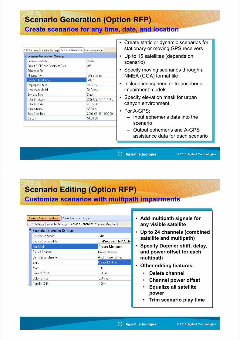
N7609B User Interface Real-time Individual Satellite Control
Reduce power in
Turn off these5 satellites
Reduce power in these 3 satellitesby 6 dB
Screen shot from u-Center software by u-blox AGN7609B User Interface
© 2010 Agilent Technologies
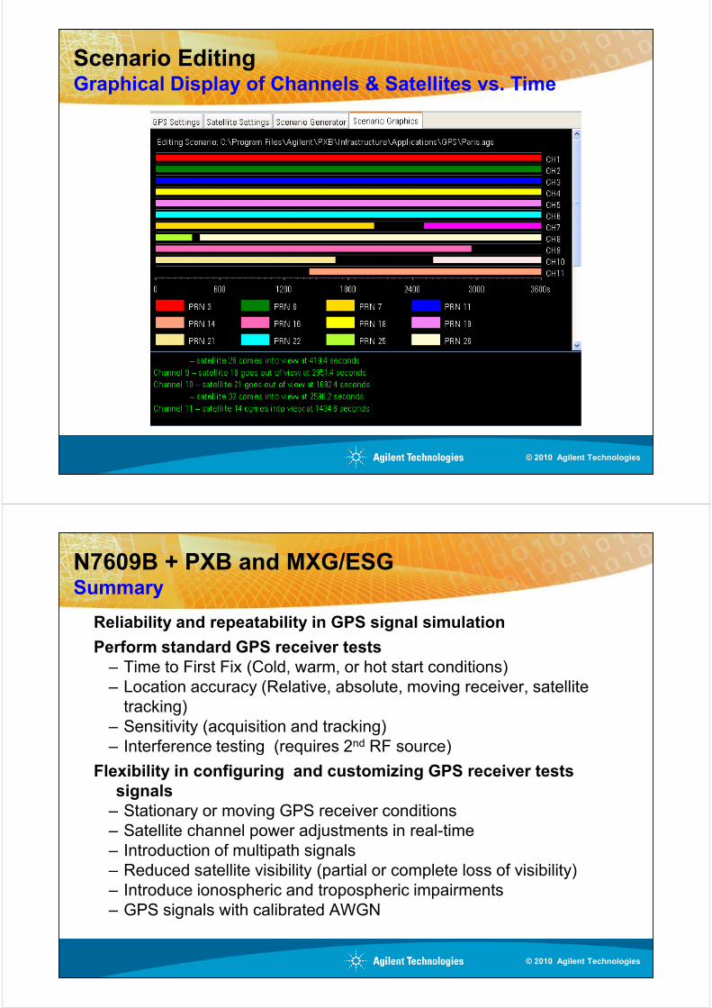
24 Channel Simulation Static Test Mode
Test satellite tracking capability of a GPS receiver or IC
• 24 channels
• Select SV PRN ID
• Individual power, delay (in chips or ms), and Doppler shift settings
• Custom 30-bit GPS word input
• Unlimited playback time
© 2010 Agilent Technologies
Scenario Generation (Option RFP)
• Create static or dynamic scenarios for
stationary or moving GPS receivers
• Up to 15 satellites (depends on
scenario)
• Specify moving scenarios through a
NMEA (GGA) format file
• Include ionospheric or tropospheric
Create scenarios for any time, date, and location
• Include ionospheric or tropospheric
impairment models
• Specify elevation mask for urban
canyon environment
• For A-GPS:
– Input ephemeris data into the
scenario
– Output ephemeris and A-GPS
assistance data for each scenario
© 2010 Agilent Technologies
• Add multipath signals for
any visible satellite
• Up to 24 channels (combined
satellite and multipath)
• Specify Doppler shift, delay,
and power offset for each
Customize scenarios with multipath impairments
Scenario Editing (Option RFP)
multipath
• Other editing features:
• Delete channel
• Channel power offset
• Equalize all satellite
power
• Trim scenario play time
© 2010 Agilent Technologies
Scenario EditingGraphical Display of Channels & Satellites vs. Time
© 2010 Agilent Technologies
N7609B + PXB and MXG/ESG Summary
Reliability and repeatability in GPS signal simulation
Perform standard GPS receiver tests– Time to First Fix (Cold, warm, or hot start conditions)
– Location accuracy (Relative, absolute, moving receiver, satellite
tracking)
– Sensitivity (acquisition and tracking)
– Interference testing (requires 2nd RF source)
Flexibility in configuring and customizing GPS receiver tests signals
– Stationary or moving GPS receiver conditions
– Satellite channel power adjustments in real-time
– Introduction of multipath signals
– Reduced satellite visibility (partial or complete loss of visibility)
– Introduce ionospheric and tropospheric impairments
– GPS signals with calibrated AWGN
© 2010 Agilent Technologies
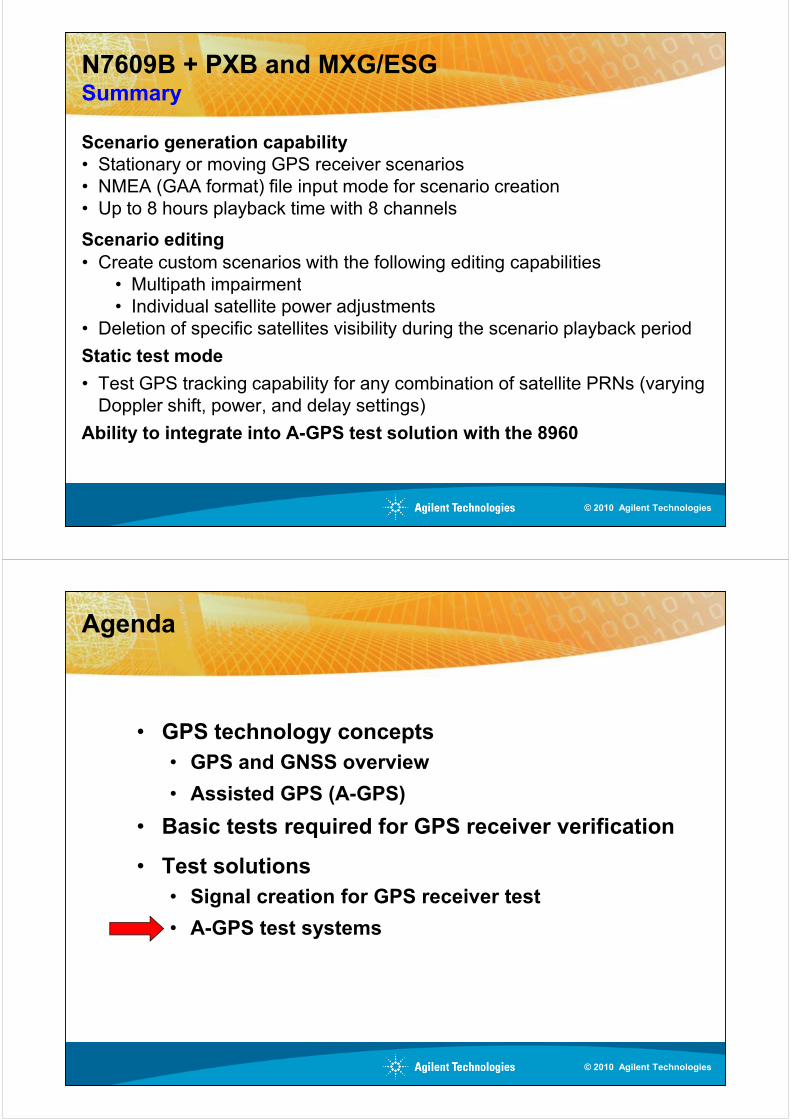
N7609B + PXB and MXG/ESGSummary
Scenario generation capability• Stationary or moving GPS receiver scenarios
• NMEA (GAA format) file input mode for scenario creation
• Up to 8 hours playback time with 8 channels
Scenario editing
• Create custom scenarios with the following editing capabilities
• Multipath impairment• Multipath impairment
• Individual satellite power adjustments
• Deletion of specific satellites visibility during the scenario playback period
Static test mode
• Test GPS tracking capability for any combination of satellite PRNs (varying
Doppler shift, power, and delay settings)
Ability to integrate into A-GPS test solution with the 8960
© 2010 Agilent Technologies
Agenda
• GPS technology concepts
• GPS and GNSS overview
• Assisted GPS (A-GPS)
• Basic tests required for GPS receiver verification
• Test solutions
• Signal creation for GPS receiver test
• A-GPS test systems
© 2010 Agilent Technologies
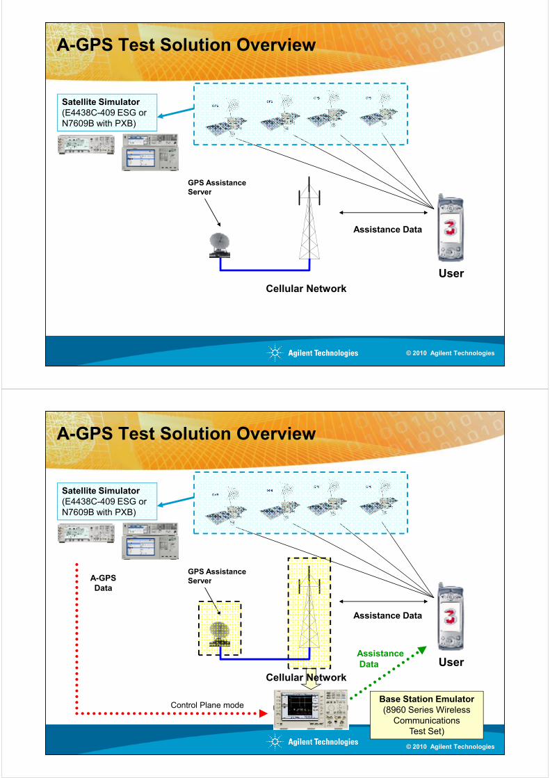
A-GPS Test Solution Overview
GPS AssistanceServer
Satellite Simulator(E4438C-409 ESG or
N7609B with PXB)
User
Assistance Data
Cellular Network
Server
© 2010 Agilent Technologies
A-GPS Test Solution Overview
GPS AssistanceServer
Satellite Simulator(E4438C-409 ESG or
N7609B with PXB)
A-GPS
User
Assistance Data
Cellular Network
Base Station Emulator(8960 Series Wireless
Communications
Test Set)
ServerData
Control Plane mode
AssistanceData
© 2010 Agilent Technologies
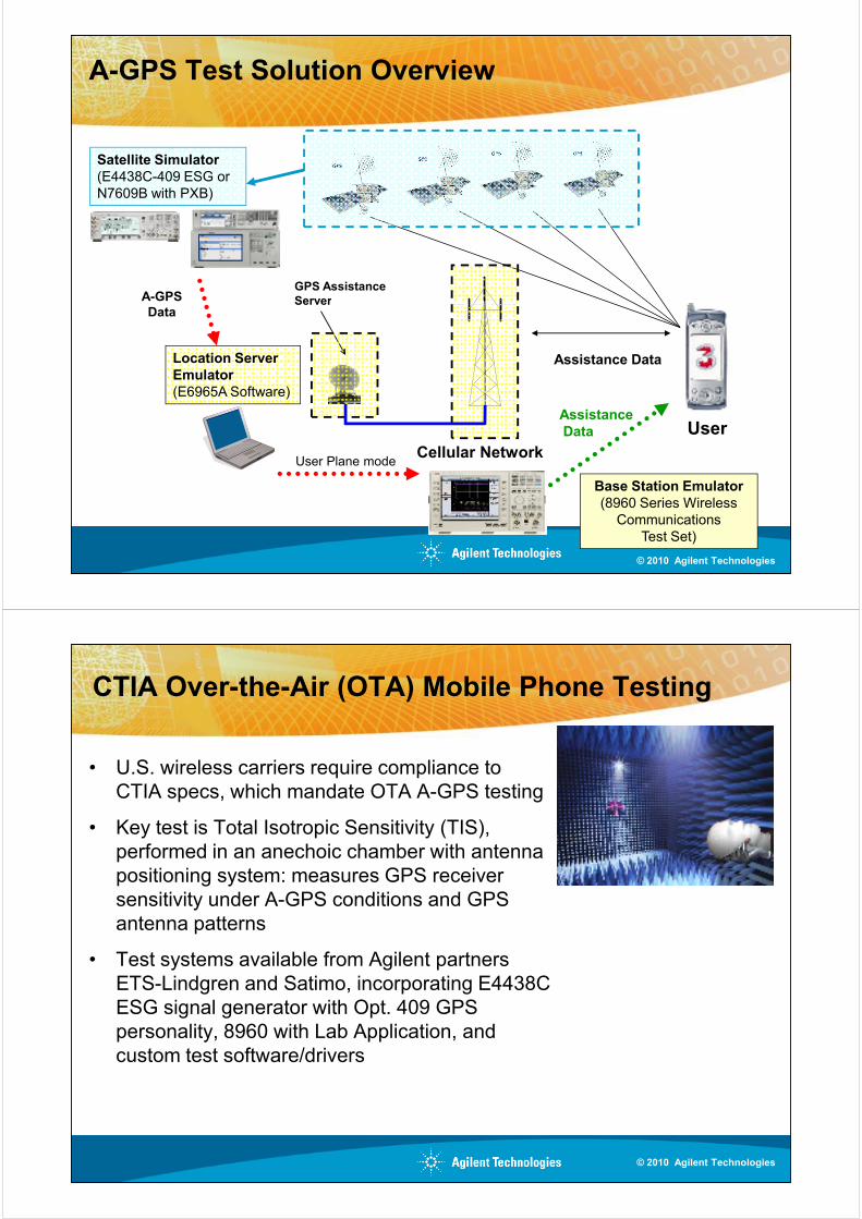
A-GPS Test Solution Overview
GPS AssistanceServer
Satellite Simulator(E4438C-409 ESG or
N7609B with PXB)
A-GPS
User
Assistance Data
Cellular Network
Base Station Emulator(8960 Series Wireless
Communications
Test Set)
Server
Location Server Emulator(E6965A Software)
Data
User Plane mode
AssistanceData
© 2010 Agilent Technologies
CTIA Over-the-Air (OTA) Mobile Phone Testing
• U.S. wireless carriers require compliance to
CTIA specs, which mandate OTA A-GPS testing
• Key test is Total Isotropic Sensitivity (TIS),
performed in an anechoic chamber with antenna
positioning system: measures GPS receiver
sensitivity under A-GPS conditions and GPS
antenna patternsantenna patterns
• Test systems available from Agilent partners
ETS-Lindgren and Satimo, incorporating E4438C
ESG signal generator with Opt. 409 GPS
personality, 8960 with Lab Application, and
custom test software/drivers
© 2010 Agilent Technologies
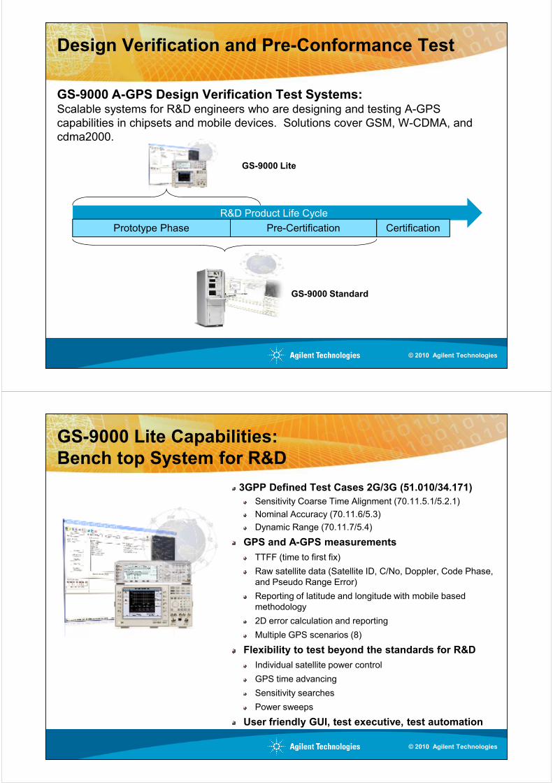
Design Verification and Pre-Conformance Test
GS-9000 A-GPS Design Verification Test Systems:Scalable systems for R&D engineers who are designing and testing A-GPS
capabilities in chipsets and mobile devices. Solutions cover GSM, W-CDMA, and
cdma2000.
GS-9000 Lite
R&D Product Life Cycle
Prototype Phase Pre-Certification Certification
GS-9000 Standard
© 2010 Agilent Technologies
GS-9000 Lite Capabilities:
Bench top System for R&D
3GPP Defined Test Cases 2G/3G (51.010/34.171)
Sensitivity Coarse Time Alignment (70.11.5.1/5.2.1)
Nominal Accuracy (70.11.6/5.3)
Dynamic Range (70.11.7/5.4)
GPS and A-GPS measurements
TTFF (time to first fix)
Raw satellite data (Satellite ID, C/No, Doppler, Code Phase,
and Pseudo Range Error)and Pseudo Range Error)
Reporting of latitude and longitude with mobile based
methodology
2D error calculation and reporting
Multiple GPS scenarios (8)
Flexibility to test beyond the standards for R&D
Individual satellite power control
GPS time advancing
Sensitivity searches
Power sweeps
User friendly GUI, test executive, test automation
© 2010 Agilent Technologies
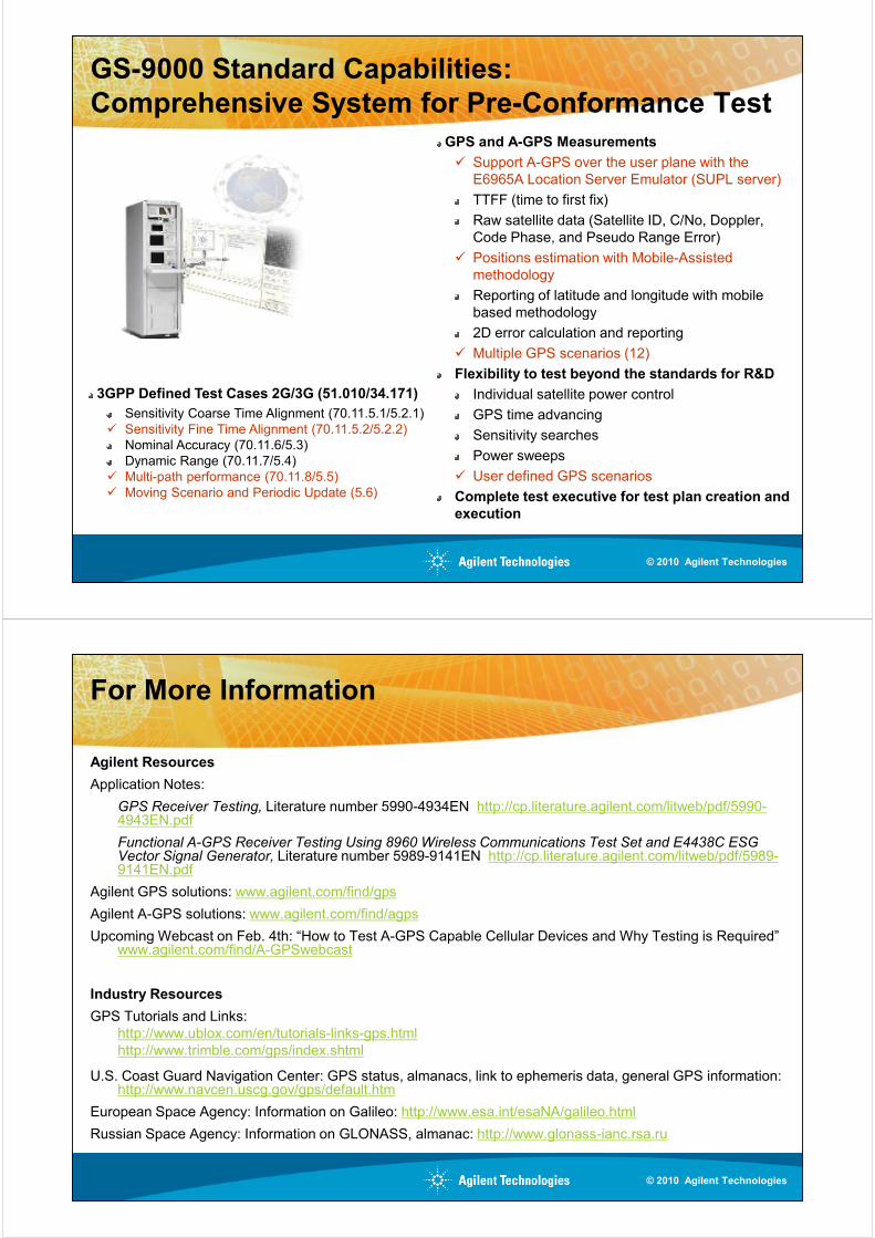
GS-9000 Standard Capabilities:
Comprehensive System for Pre-Conformance Test
GPS and A-GPS Measurements
� Support A-GPS over the user plane with the
E6965A Location Server Emulator (SUPL server)
TTFF (time to first fix)
Raw satellite data (Satellite ID, C/No, Doppler,
Code Phase, and Pseudo Range Error)
� Positions estimation with Mobile-Assisted
methodology
Reporting of latitude and longitude with mobile
based methodologybased methodology
2D error calculation and reporting
� Multiple GPS scenarios (12)
Flexibility to test beyond the standards for R&D
Individual satellite power control
GPS time advancing
Sensitivity searches
Power sweeps
� User defined GPS scenarios
Complete test executive for test plan creation and execution
3GPP Defined Test Cases 2G/3G (51.010/34.171)
Sensitivity Coarse Time Alignment (70.11.5.1/5.2.1)
� Sensitivity Fine Time Alignment (70.11.5.2/5.2.2)
Nominal Accuracy (70.11.6/5.3)
Dynamic Range (70.11.7/5.4)
� Multi-path performance (70.11.8/5.5)
� Moving Scenario and Periodic Update (5.6)
© 2010 Agilent Technologies
For More Information
Agilent Resources
Application Notes:
GPS Receiver Testing, Literature number 5990-4934EN http://cp.literature.agilent.com/litweb/pdf/5990-4943EN.pdf
Functional A-GPS Receiver Testing Using 8960 Wireless Communications Test Set and E4438C ESG Vector Signal Generator, Literature number 5989-9141EN http://cp.literature.agilent.com/litweb/pdf/5989-9141EN.pdf
Agilent GPS solutions: www.agilent.com/find/gps
Agilent A-GPS solutions: www.agilent.com/find/agps
Upcoming Webcast on Feb. 4th: “How to Test A-GPS Capable Cellular Devices and Why Testing is Required” www.agilent.com/find/A-GPSwebcast
Industry Resources
GPS Tutorials and Links:
http://www.ublox.com/en/tutorials-links-gps.html
http://www.trimble.com/gps/index.shtml
U.S. Coast Guard Navigation Center: GPS status, almanacs, link to ephemeris data, general GPS information: http://www.navcen.uscg.gov/gps/default.htm
European Space Agency: Information on Galileo: http://www.esa.int/esaNA/galileo.html
Russian Space Agency: Information on GLONASS, almanac: http://www.glonass-ianc.rsa.ru
© 2010 Agilent Technologies

© 2010 Agilent Technologies