Embed Size (px)
Citation preview
1
International optical convergence technology conference 2015 Tokyo Univ. of Agri. & Tech.
Challenges forNext-Generation 3D Displays
Yasuhiro Takaki
Institute of EngineeringTokyo University of Agriculture and Technology
2
International optical convergence technology conference 2015 Tokyo Univ. of Agri. & Tech.
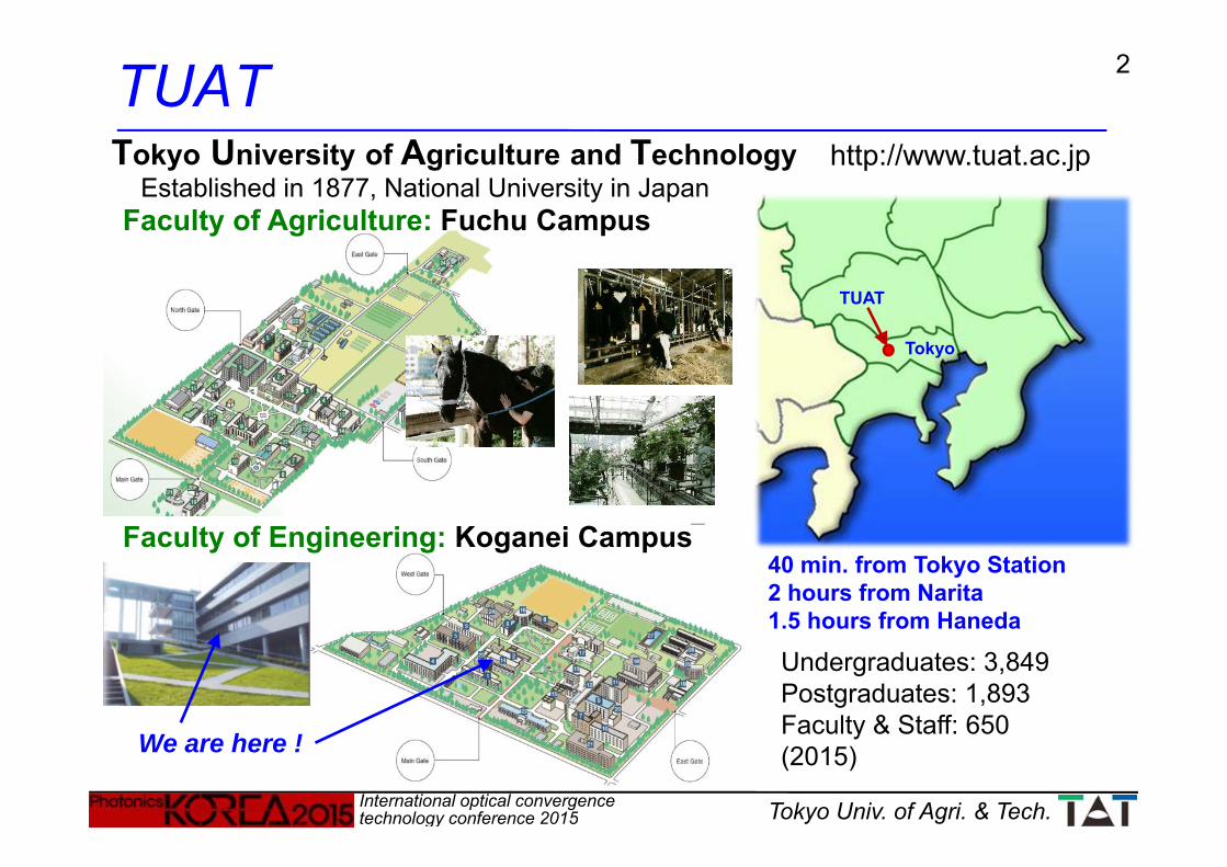
TUAT
Undergraduates: 3,849Postgraduates: 1,893Faculty & Staff: 650(2015)
http://www.tuat.ac.jpTokyo University of Agriculture and Technology
Tokyo
TUAT
We are here !
40 min. from Tokyo Station2 hours from Narita1.5 hours from Haneda
Established in 1877, National University in Japan Faculty of Agriculture: Fuchu Campus
Faculty of Engineering: Koganei Campus

3
International optical convergence technology conference 2015 Tokyo Univ. of Agri. & Tech.
Why Do We Need 3D Displays ?1. Depth informationStructures of objects and scenes can be
understood easily and precisely.
2. High reality & presenceWe feel as if real objects existed or we were
in real world.
3. Advanced man-machine interfaceDigital information is provided at the same
depth of real objects.
4. Object appearance reproductionDirectional light reflection on object surfaces
causes gloss, transparency, softness, etc.
2D 3D
4
International optical convergence technology conference 2015 Tokyo Univ. of Agri. & Tech.
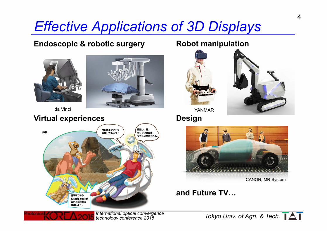
Robot manipulation
Design
and Future TV…
Effective Applications of 3D DisplaysEndoscopic & robotic surgery
Virtual experiencesYANMARda Vinci
CANON, MR System
5
International optical convergence technology conference 2015 Tokyo Univ. of Agri. & Tech.
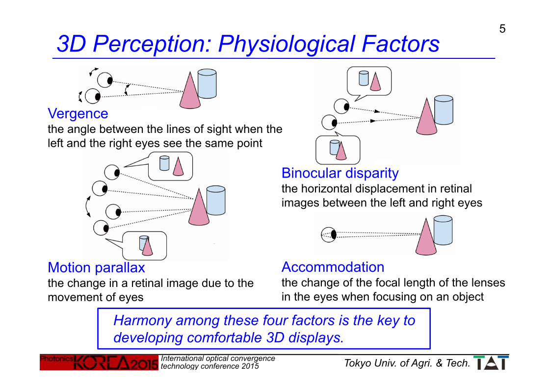
3D Perception: Physiological Factors
Motion parallaxthe change in a retinal image due to the movement of eyes
Harmony among these four factors is the key to developing comfortable 3D displays.
Vergencethe angle between the lines of sight when the left and the right eyes see the same point
Accommodationthe change of the focal length of the lenses in the eyes when focusing on an object
Binocular disparitythe horizontal displacement in retinal images between the left and right eyes

6
International optical convergence technology conference 2015 Tokyo Univ. of Agri. & Tech.
Psychological factors are important in the creation of effective 3D content.
Shadow
Texture gradient
Relative size
Superposition
Perspective
Aerialperspective
3D Perception: Psychological Factors
7
International optical convergence technology conference 2015 Tokyo Univ. of Agri. & Tech.
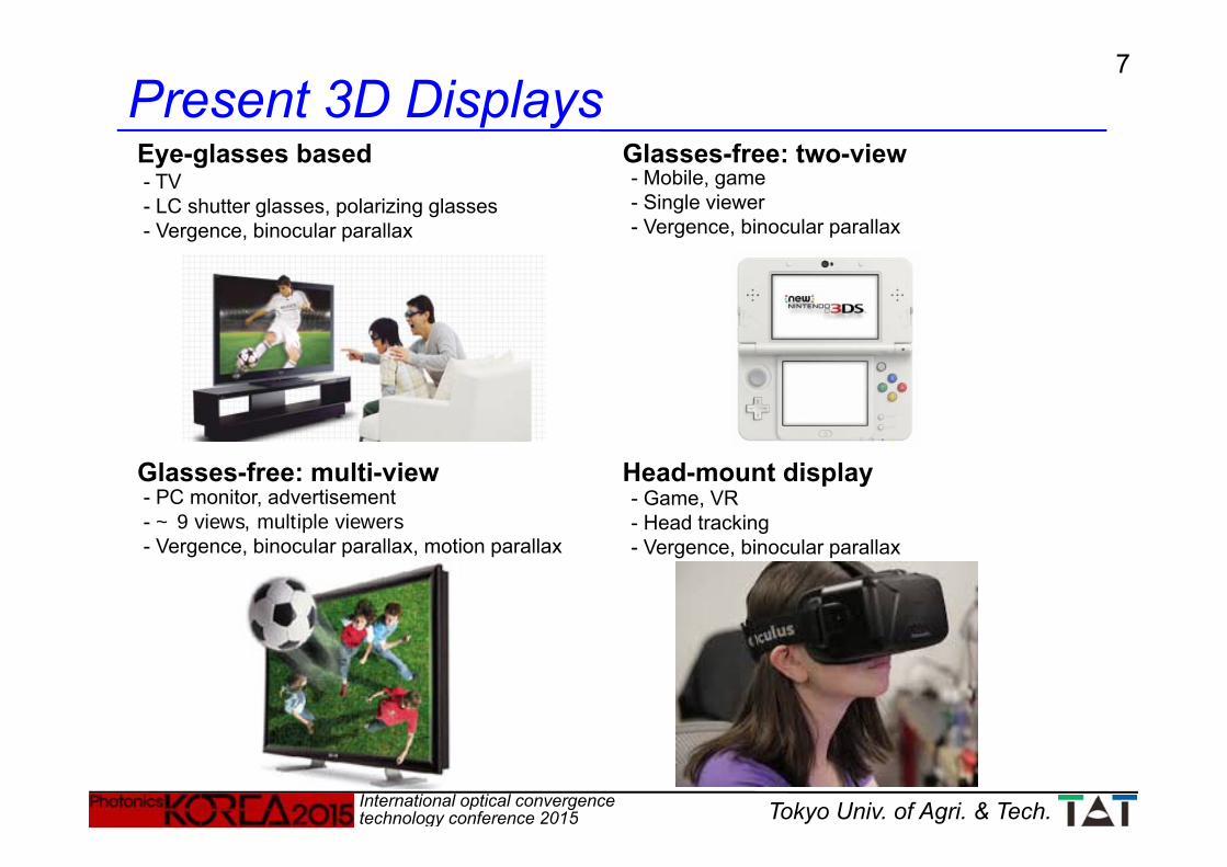
Present 3D DisplaysGlasses-free: two-viewEye-glasses based
Head-mount displayGlasses-free: multi-view
- TV- LC shutter glasses, polarizing glasses- Vergence, binocular parallax
- Mobile, game- Single viewer- Vergence, binocular parallax
- PC monitor, advertisement- ~ 9 views, multiple viewers- Vergence, binocular parallax, motion parallax
- Game, VR- Head tracking- Vergence, binocular parallax
8
International optical convergence technology conference 2015 Tokyo Univ. of Agri. & Tech.
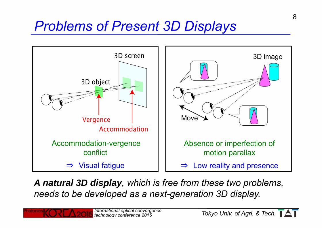
Problems of Present 3D Displays
Accommodation-vergence conflict
⇒ Visual fatigue
Absence or imperfection of motion parallax
⇒ Low reality and presence
3D image
Move
A natural 3D display, which is free from these two problems, needs to be developed as a next-generation 3D display.

9
International optical convergence technology conference 2015 Tokyo Univ. of Agri. & Tech.
Wavefront reconstructionHolography
Ray reconstructionMulti-view, integral imaging
Volume reconstructionStack of 2D images
Only diffusive objects can be displayed.Not suitable for displaying real 3D images.
Classification of 3D Display Techniques

10
International optical convergence technology conference 2015 Tokyo Univ. of Agri. & Tech.
Spherical waves produce sharp points which constitute 3D images.→ Eyes can focus on 3D images.The vergence-accommodation conflict does not occur.
Holography
Wavefront emitted from 3D objects are reconstructed.
Accommodation(Eye focus)+ Vergence
Hologram
Holography was invented by D. Gabor, who was awarded the Nobel Prize in 1971.
Vergence
Binocular disparity
Accommodation
Motion parallax
11
International optical convergence technology conference 2015 Tokyo Univ. of Agri. & Tech.
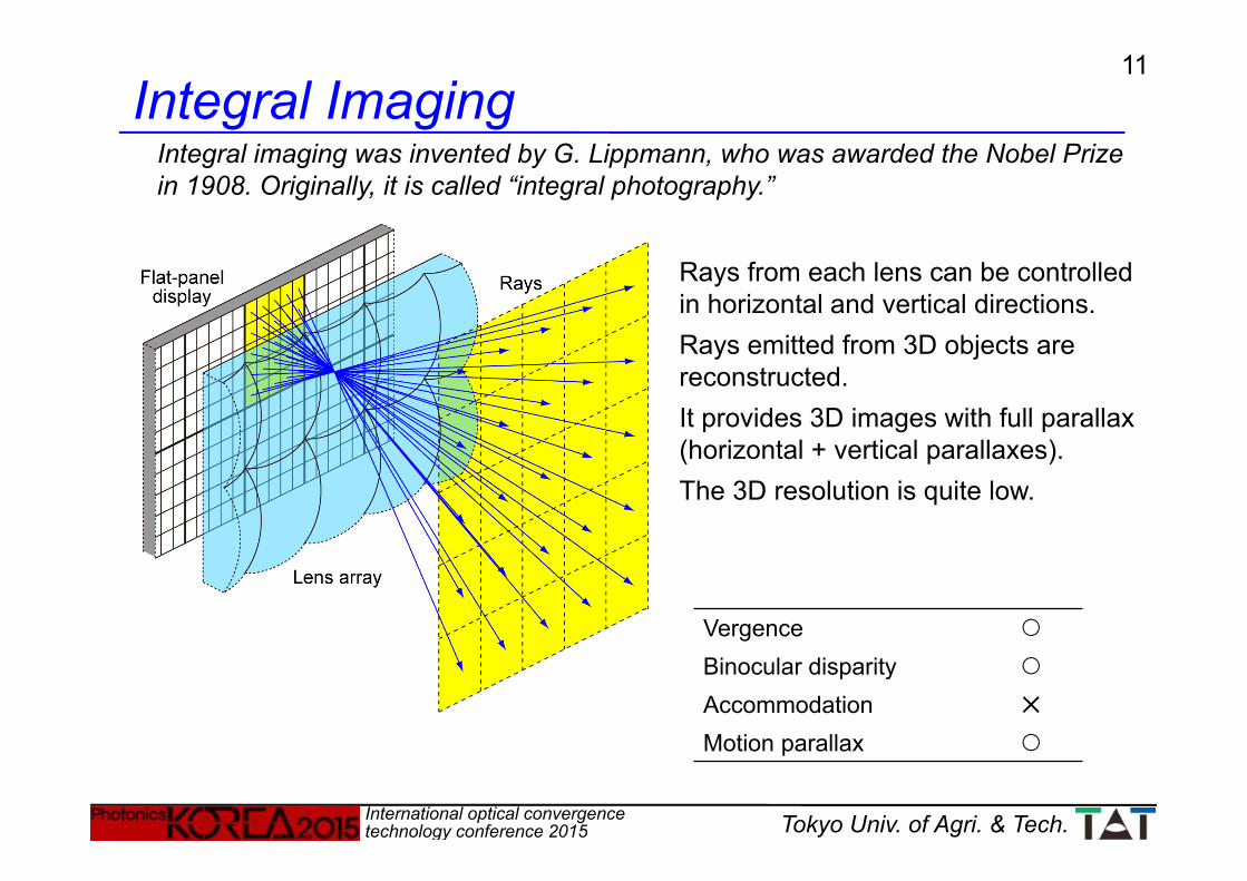
Integral ImagingIntegral imaging was invented by G. Lippmann, who was awarded the Nobel Prize in 1908. Originally, it is called “integral photography.”
Rays from each lens can be controlled in horizontal and vertical directions.Rays emitted from 3D objects are reconstructed.It provides 3D images with full parallax (horizontal + vertical parallaxes).The 3D resolution is quite low.
Vergence
Binocular disparity
Accommodation ✕
Motion parallax

12
International optical convergence technology conference 2015 Tokyo Univ. of Agri. & Tech.
(Lens pitch) ≤ (pixel group pitch)Each lens images multiple pixels behind it to generate multiple viewpoints.Images generated by all lens are superimposed at a certain distance.Through viewpoints, corresponding parallax images can be viewed.3D images with horizontal parallax are provided.
Vergence
Binocular disparity
Accommodation ✕
Motion parallax
(3D resolution) = (Flat-panel resolution) / (Number of views)
Multi-view Display

13
International optical convergence technology conference 2015 Tokyo Univ. of Agri. & Tech.
Pupil diameter: 2 ~ 8 mm (average 5 mm)→ Interval of viewpoints: < 5 mm
Number of viewpoints: 30 ~ 100 (horizontal)
The interval of viewpoints is made smaller than the pupil diameter of eyes.
When eyes focus on display screen
When eyes focus on 3D images
Sharpimages
Blurredimages
Super Multi-view Display Technique
Eyes can focus on 3D images.→ The vergence-accommodation conflict does not occur.
Vergence
Binocular disparity
Accommodation
Motion parallax
→ Two or more rays passing through an identical point in the space enter the pupil simultaneously.
14
International optical convergence technology conference 2015 Tokyo Univ. of Agri. & Tech.
Focus
FocusFocus
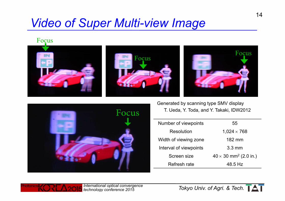
T. Ueda, Y. Toda, and Y. Takaki, IDW2012
Number of viewpoints 55
Resolution 1,024 768
Width of viewing zone 182 mm
Interval of viewpoints 3.3 mm
Screen size 40 30 mm2 (2.0 in.)
Refresh rate 48.5 Hz
Video of Super Multi-view Image
Generated by scanning type SMV display
15
International optical convergence technology conference 2015 Tokyo Univ. of Agri. & Tech.
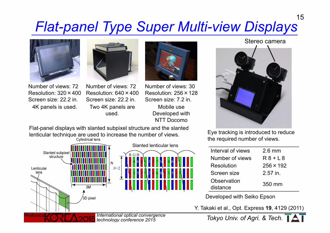
Number of views: 72Resolution: 320×400Screen size: 22.2 in.
Number of views: 72Resolution: 640×400Screen size: 22.2 in.
Number of views: 30Resolution: 256×128Screen size: 7.2 in.
Mobile useDeveloped with NTT Docomo
Stereo camera
Interval of views 2.6 mmNumber of views R 8 + L 8Resolution 256×192Screen size 2.57 in.Observationdistance 350 mm
Flat-panel Type Super Multi-view Displays
Two 4K panels are used.
4K panels is used.
Flat-panel displays with slanted subpixel structure and the slanted lenticular technique are used to increase the number of views. Eye tracking is introduced to reduce
the required number of views.
Y. Takaki et al., Opt. Express 19, 4129 (2011)
Slanted lenticular lens
Developed with Seiko Epson
16
International optical convergence technology conference 2015 Tokyo Univ. of Agri. & Tech.
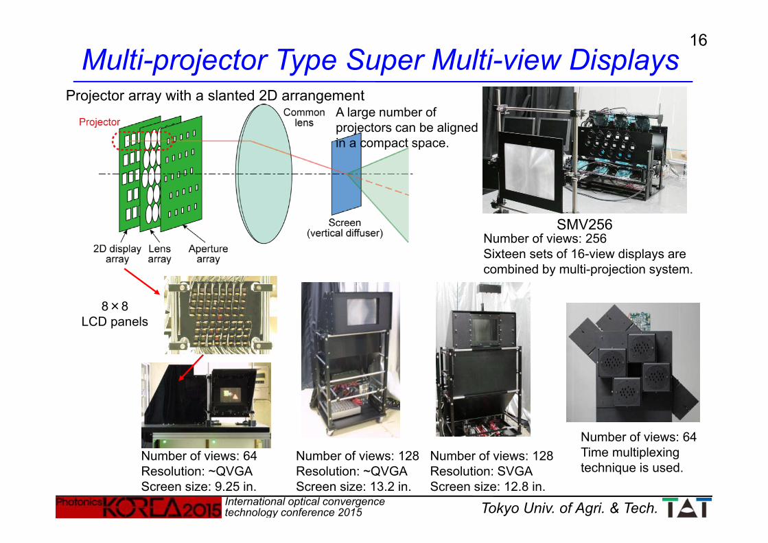
Projector array with a slanted 2D arrangement
Number of views: 64Resolution: ~QVGAScreen size: 9.25 in.
8×8LCD panels
Number of views: 64Time multiplexing technique is used.
SMV256Number of views: 256Sixteen sets of 16-view displays are combined by multi-projection system.
A large number of projectors can be aligned in a compact space.
Number of views: 128Resolution: ~QVGAScreen size: 13.2 in.
Number of views: 128Resolution: SVGAScreen size: 12.8 in.
Multi-projector Type Super Multi-view Displays

17
International optical convergence technology conference 2015 Tokyo Univ. of Agri. & Tech.
Auto refractometerFR-5000S(Grand Seiko Corp.)
Accommodation Measurement
Visual function measurement equipment specialized for 3D displaysJointly developed with TOPCON Corp. under the SCOPE project
R & L Accommodation + Vergence+ R & L Pupil diameters
Acc (L)
Acc (R)
Vergence
Pupil (R)
Pupil (L)
Acc
[D]
Acc
[D]
Verg
ence
Dia
m. [
mm
]D
iam
. [m
m]
18
International optical convergence technology conference 2015 Tokyo Univ. of Agri. & Tech.
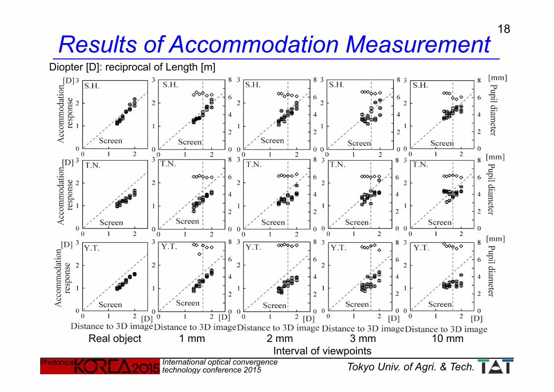
Real object 1 mm 2 mm 3 mm 10 mm
Results of Accommodation Measurement
Interval of viewpoints
Diopter [D]: reciprocal of Length [m]
19
International optical convergence technology conference 2015 Tokyo Univ. of Agri. & Tech.
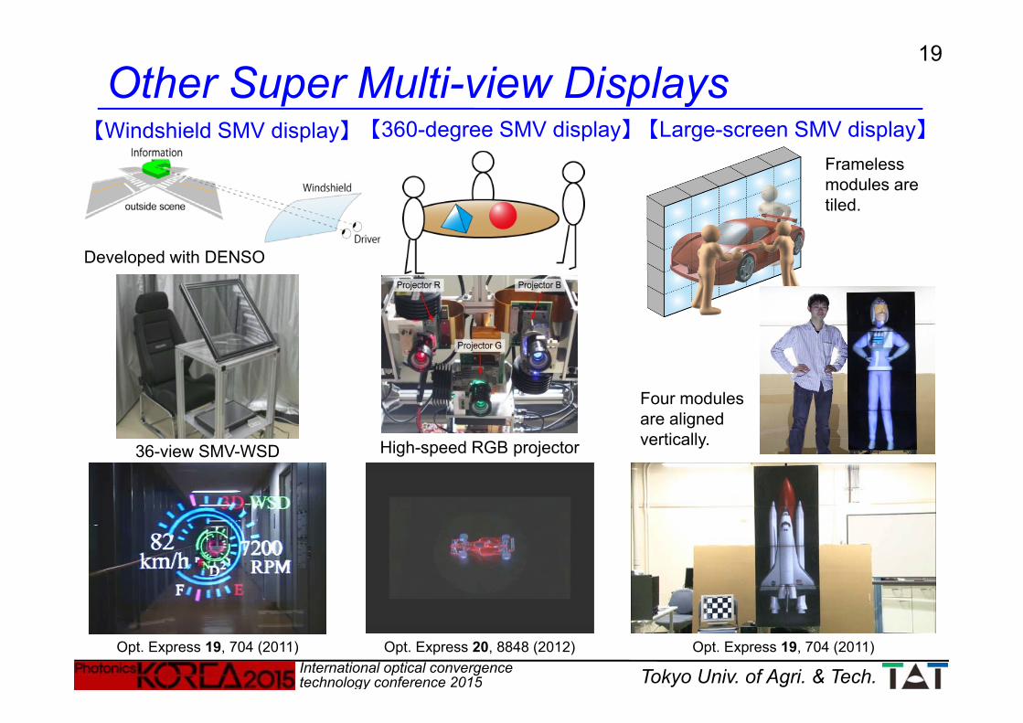
Other Super Multi-view Displays【Windshield SMV display】
Opt. Express 19, 704 (2011)Opt. Express 20, 8848 (2012)
36-view SMV-WSD
【360-degree SMV display】 【Large-screen SMV display】Frameless modules are tiled.
Four modules are aligned vertically.High-speed RGB projector
Opt. Express 19, 704 (2011)
Developed with DENSO
20
International optical convergence technology conference 2015 Tokyo Univ. of Agri. & Tech.
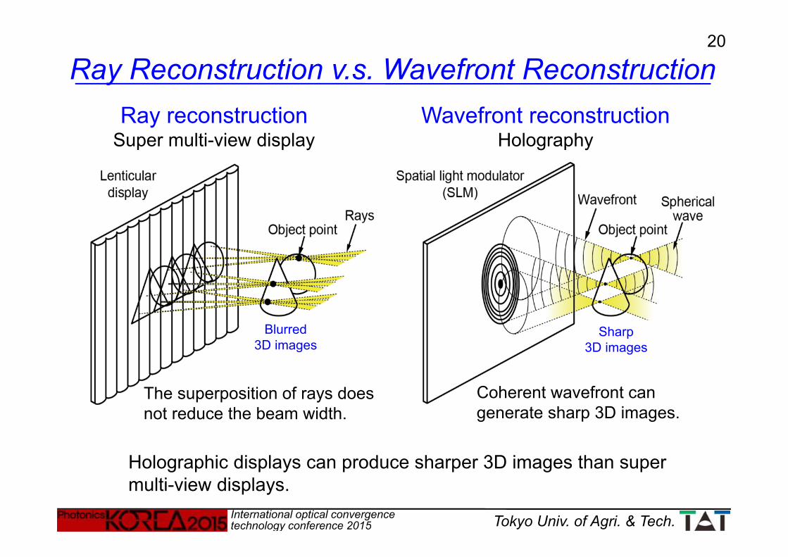
Wavefront reconstructionHolography
Holographic displays can produce sharper 3D images than super multi-view displays.
Ray Reconstruction v.s. Wavefront ReconstructionRay reconstruction
Super multi-view display
The superposition of rays does not reduce the beam width.
Coherent wavefront can generate sharp 3D images.
Blurred3D images
Sharp3D images
21
International optical convergence technology conference 2015 Tokyo Univ. of Agri. & Tech.
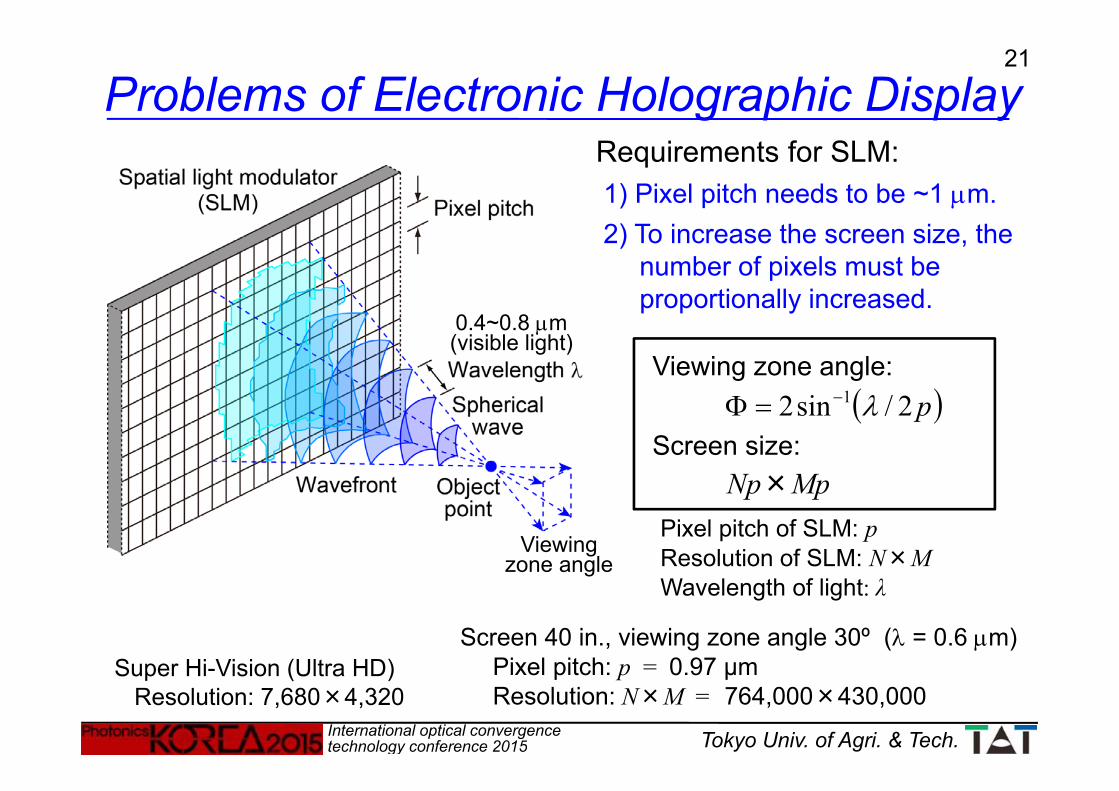
Requirements for SLM:1) Pixel pitch needs to be ~1 m.2) To increase the screen size, the
number of pixels must be proportionally increased.
0.4~0.8 m(visible light)
Pixel pitch of SLM: pResolution of SLM: N×MWavelength of light: λ
Viewing zone angle: p2/sin2 1
Screen size:Np×Mp
Screen 40 in., viewing zone angle 30º ( = 0.6 m)Pixel pitch: p = 0.97 μmResolution: N×M = 764,000×430,000
Viewingzone angle
Super Hi-Vision (Ultra HD) Resolution: 7,680×4,320
Problems of Electronic Holographic Display

22
International optical convergence technology conference 2015 Tokyo Univ. of Agri. & Tech.
TAO (Japan), 5 SLMsSPIE 2652, 1519 (1996)
SLM
SLM
Seoul National University (Korea), 12 SLMsOpt. Express 16, 12372 (2008)
MIT (U.S.A.)
Horizontal-Parallax-Only (HPO) hologram
Previously Proposed Holographic Displays【Multiple SLMs】 【AOM + 2D scanning】
SPIE 1212, 174 (1990)J.Opt.Soc.Am. 9, 1969 (1992)
23
International optical convergence technology conference 2015 Tokyo Univ. of Agri. & Tech.
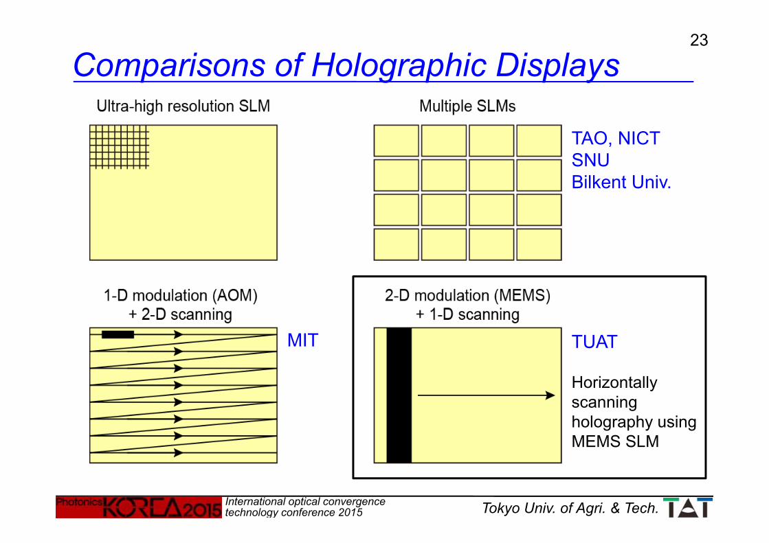
TUAT
Horizontally scanning holography using MEMS SLM
MIT
TAO, NICTSNUBilkent Univ.
Comparisons of Holographic Displays

24
International optical convergence technology conference 2015 Tokyo Univ. of Agri. & Tech.
Anamorphic imaging system:Horizontal: reduce pixel pitch Vertical: increase image height
Horizontal Scanning:Increase image width
→ Viewing zone angle increases
→ Screen size increases
Y. Takaki et al., Appl. Opt. 48, 3255 (2009)Y. Takaki et al., Opt. Express 18, 11327 (2010)
SSB filter: single sideband filter
Screen scanning systemHorizontally Scanning Holography Using MEMS-SLM

25
International optical convergence technology conference 2015 Tokyo Univ. of Agri. & Tech.
MEMS-SLM
Mx = 0.183
My = 5.00
Elementary hologramSize: 2.56×52.5 mm2
Horizontal pixel pitch:2.5 μm
Horizontal viewing angle:15 º
Galvano mirrorMicroMaxTMSeries671
Scanning frequency: 60 HzScan angle:±18.1ºScreen size: 3.5 in.
(73.1×52.5 mm2)Number of elementary
holograms:222
Frame rate: 13.333 kHzResolution: 1,024×768Pixel pitch: 13.68 μmScreen size: 0.7 in.
(14.0×10.5 mm2)
Horizontal scanner
Digital Micromirror Device (DMD)
DiscoveryTM3000
Anamorphic imaging system
Screen Scanning System: Experimental System
26
International optical convergence technology conference 2015 Tokyo Univ. of Agri. & Tech.
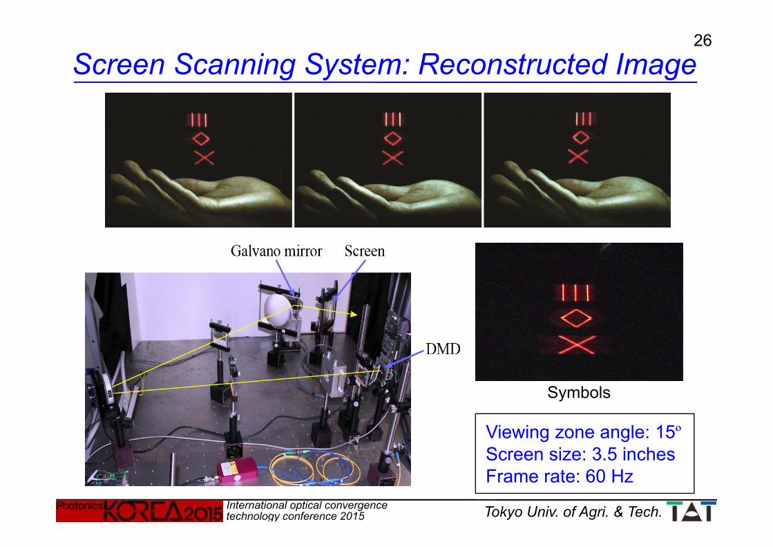
Viewing zone angle: 15ºScreen size: 3.5 inchesFrame rate: 60 Hz
Symbols
Screen Scanning System: Reconstructed Image

27
International optical convergence technology conference 2015 Tokyo Univ. of Agri. & Tech.
Pixel pitch: 2.5 m (horizontal)Viewing zone angles:
Red: 14.7˚, Green: 11.8˚, Blue: 10.2˚Screen size: 6.2 inchesFrame rate (hologram): 30 Hz
DMD Discovery 4100(Texas Instruments Inc.)
Resolution: 1,024×768Pixel pitch: 13.68 μmFrame rate: 22.727 kHz
MEMS SLM
Horizontal scannerCambridge TechnologyMicroMaxTM Series671
Scan angle: ±6.8˚Scan frequency: 30 HzMirror size: 95 ×170 mm2
LasersToptica PhotonicsFiber coupled laser diodes
R:640 nm, G:515 nm, B:445 nm
DMD screen has a structure similar to a reflective blazed grating.
R, G, and B laser lights should illuminate DMD with different appropriate angles.
Screen Scanning System: Color System
28
International optical convergence technology conference 2015 Tokyo Univ. of Agri. & Tech.
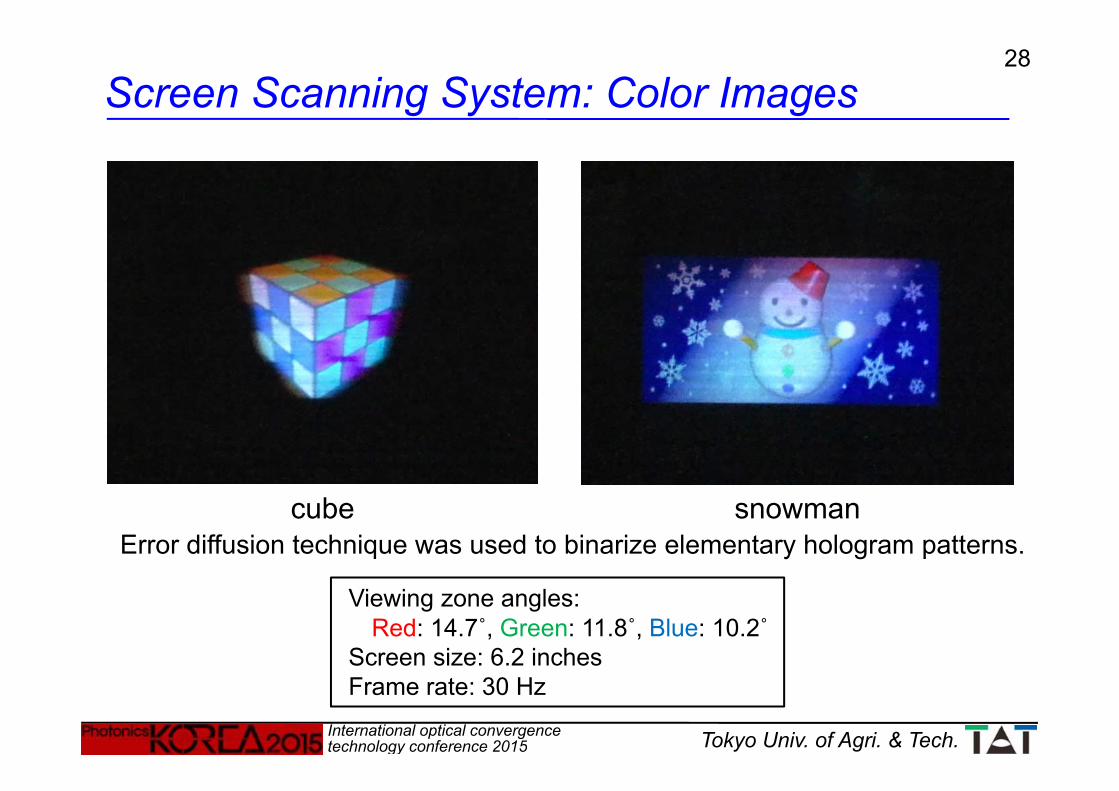
cube snowmanError diffusion technique was used to binarize elementary hologram patterns.
Viewing zone angles:Red: 14.7˚, Green: 11.8˚, Blue: 10.2˚
Screen size: 6.2 inchesFrame rate: 30 Hz
Screen Scanning System: Color Images

29
International optical convergence technology conference 2015 Tokyo Univ. of Agri. & Tech.
Auto refractometer: FR-5000S(Grand Seiko Co., Ltd.)
Test image(1.1º 1.1º) The measurements were performed for 10 s, and the responses for 2 s without
blink were averaged to obtain an experimental result.
1,100 mm
Y. Takaki and M. Yokouchi, Opt. Express 20, 3918-3931 (2012)
Accommodation Measurements
30
International optical convergence technology conference 2015 Tokyo Univ. of Agri. & Tech.
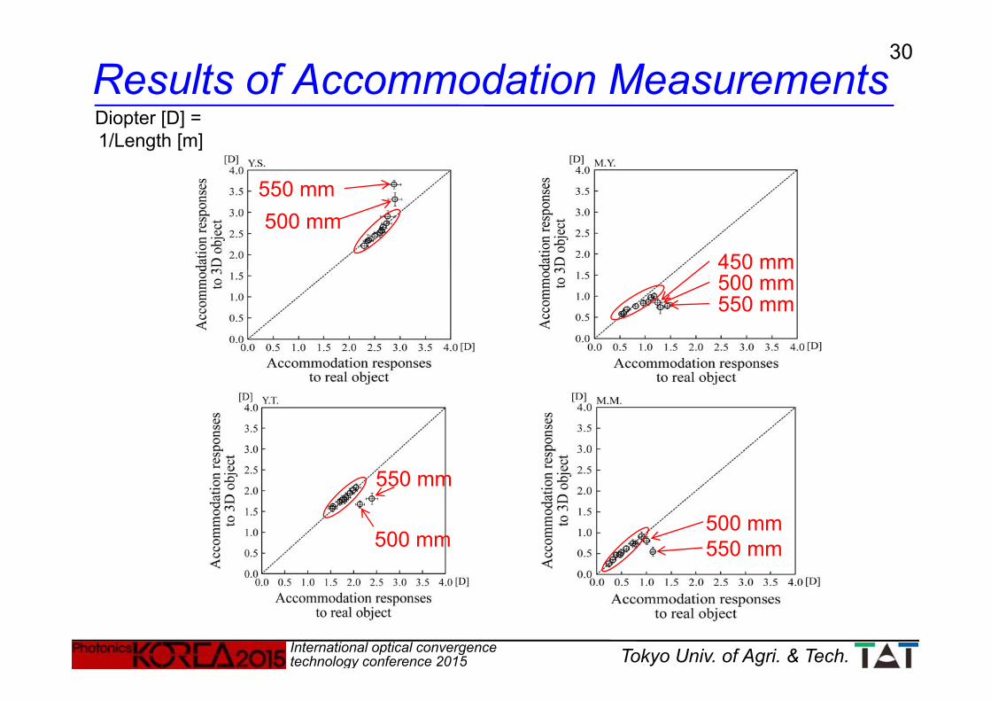
500 mm550 mm
500 mm550 mm
450 mm
550 mm500 mm
500 mm
550 mm
Diopter [D] = 1/Length [m]
Results of Accommodation Measurements
31
International optical convergence technology conference 2015 Tokyo Univ. of Agri. & Tech.
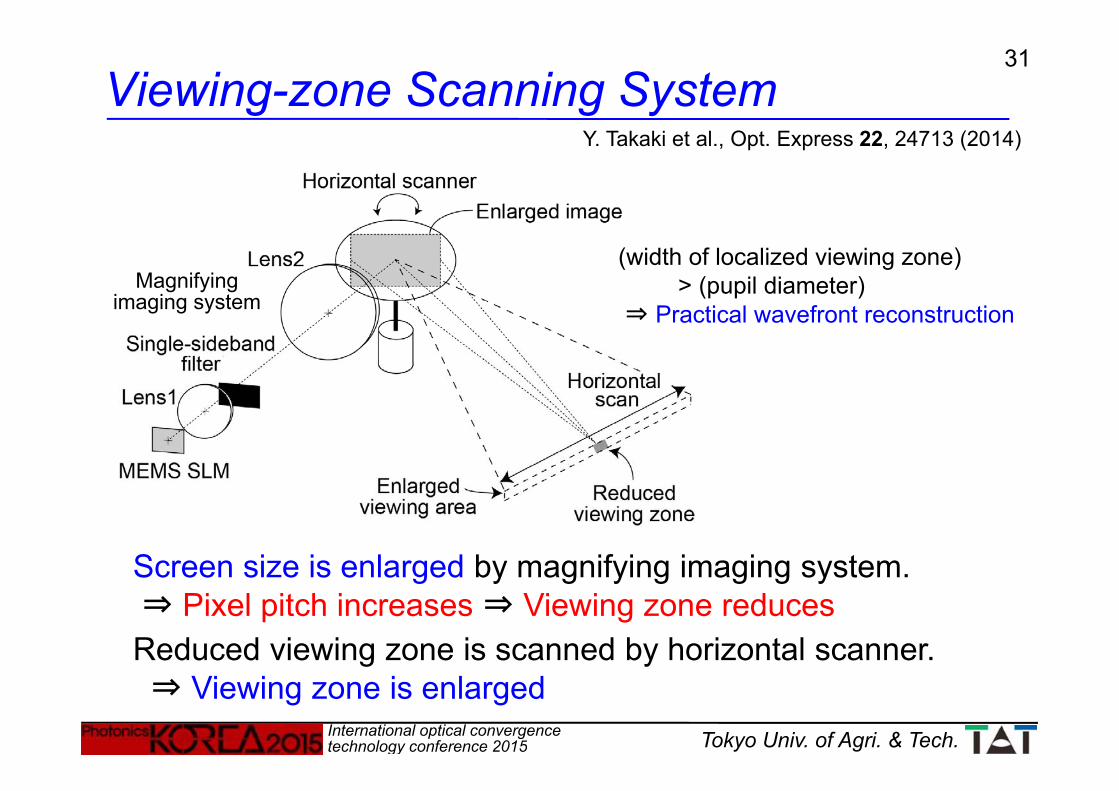
Screen size is enlarged by magnifying imaging system.⇒ Pixel pitch increases ⇒ Viewing zone reducesReduced viewing zone is scanned by horizontal scanner.⇒ Viewing zone is enlarged
(width of localized viewing zone) > (pupil diameter)
⇒ Practical wavefront reconstruction
Y. Takaki et al., Opt. Express 22, 24713 (2014)
Magnifying imaging system
Viewing-zone Scanning System
32
International optical convergence technology conference 2015 Tokyo Univ. of Agri. & Tech.
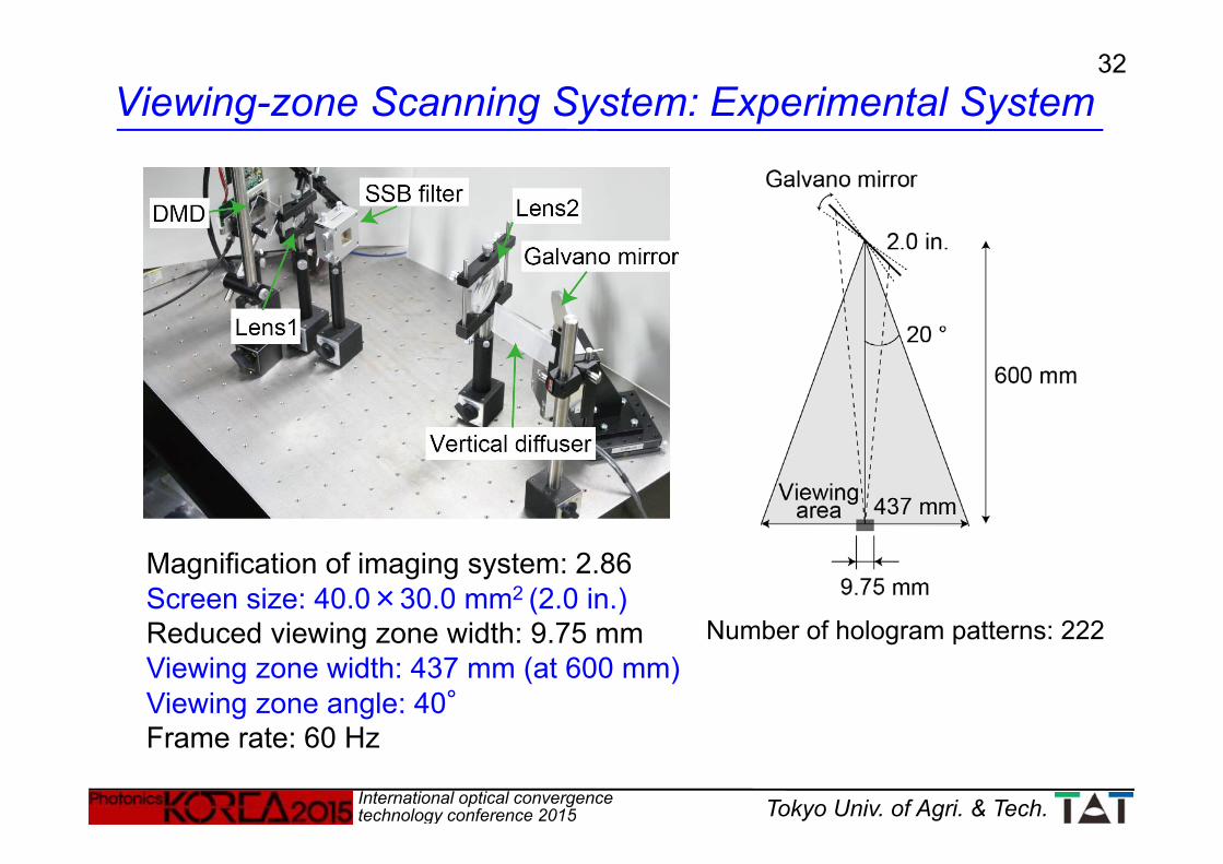
Number of hologram patterns: 222
Magnification of imaging system: 2.86Screen size: 40.0×30.0 mm2 (2.0 in.)Reduced viewing zone width: 9.75 mmViewing zone width: 437 mm (at 600 mm)Viewing zone angle: 40°Frame rate: 60 Hz
Viewing-zone Scanning System: Experimental System
33
International optical convergence technology conference 2015 Tokyo Univ. of Agri. & Tech.
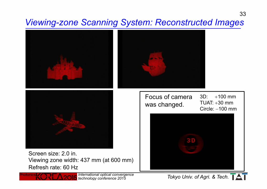
Screen size: 2.0 in.Viewing zone width: 437 mm (at 600 mm)Refresh rate: 60 Hz
3D: 100 mmTUAT: 30 mmCircle: 100 mm
Focus of camera was changed.
Viewing-zone Scanning System: Reconstructed Images

34
International optical convergence technology conference 2015 Tokyo Univ. of Agri. & Tech.
Screen size is enlarged by magnifying imaging system.
Pixel pitch increases.→ Viewing zone reduces.
Reduced viewing zone is scanned circularly by rotating lens screen.
→ Viewing zone is enlarged to 360 degrees.
Off-axis lens is used as rotating screen to generate viewing zone outside rotation axis.
T. Inoue and Y. Takaki, Opt. Express 23, 6533 (2015)
Flat-table screen is provided.
360-degree Scanning System

35
International optical convergence technology conference 2015 Tokyo Univ. of Agri. & Tech.
DMD: Discovery 4100Frame rate: 22.727 kHzResolution: 1,024×768Pixel pitch: 13.68 m
Laser: 635 nm, 23 mW
Projector Rotating screen
Rotation speed: 1,700 rpmNumber of hologram / rotation: 800Frame rate (3D): 28.4 Hz
Magnification: 5.71Screen size: 80 x 60 mm2
(Diameter 100 mm) Pixel pitch: 78.1 mReduced viewing zone: 5.81 mm x 2.91 mm
3D: 110 mm, TUAT: 90 mm, circle: 70 mm plane1: 90 mm, plane2: 110 mm
360-degree Scanning System: Experimental System
36
International optical convergence technology conference 2015 Tokyo Univ. of Agri. & Tech.
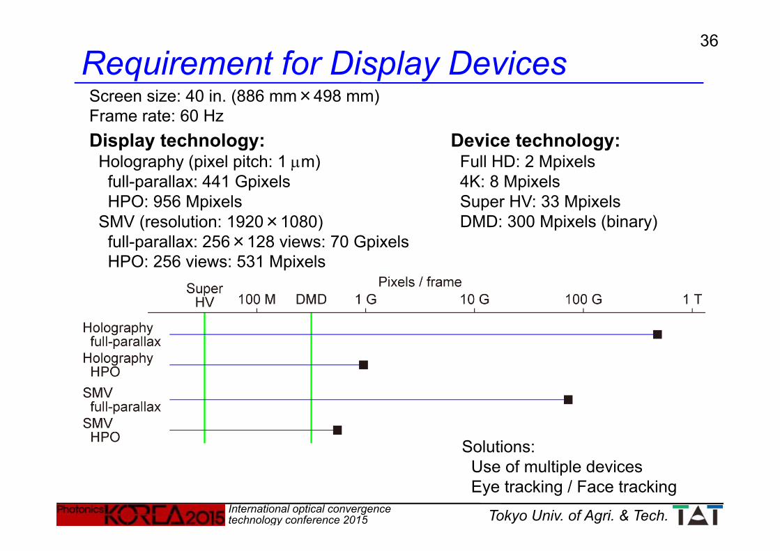
Requirement for Display Devices
Display technology: Holography (pixel pitch: 1 m)full-parallax: 441 GpixelsHPO: 956 Mpixels
SMV (resolution: 1920×1080)full-parallax: 256×128 views: 70 GpixelsHPO: 256 views: 531 Mpixels
Screen size: 40 in. (886 mm×498 mm)Frame rate: 60 Hz
Device technology: Full HD: 2 Mpixels4K: 8 MpixelsSuper HV: 33 MpixelsDMD: 300 Mpixels (binary)
Solutions:Use of multiple devicesEye tracking / Face tracking

37
International optical convergence technology conference 2015 Tokyo Univ. of Agri. & Tech.
Summary
The next-generation 3D displays should be free from visual fatigue caused by the vergence-accommodation conflict, and also provide smooth motion parallax.
Holography and SMV displays are candidates for the next-generation 3D displays.
Several types of the SMV displays, the scanning holography using MEMS SLM, and the accommodation responses were shown.
The requirement for display devices to realize these displays was discussed.

38
International optical convergence technology conference 2015 Tokyo Univ. of Agri. & Tech.
ACKNOWLEGEMENTS
Grant-in-Aid for Scientific Research, No.(B) 13555106, JSPS (2001~2002)
SCOPE, Ministry of Internal Affairs and Communications, Japan (2002~2006)
Grant-in-Aid for Scientific Research, No.(B) 15360183, JSPS (2003~2004)
Grant-in-Aid for Scientific Research, No.(B) 18360165, JSPS (2006~2007)
Grant-in-Aid for Scientific Research, No.(B) 20360153, JSPS (2008~2010)
Grant-in-Aid for Scientific Research, No.(B) 23360148, JSPS (2011~2013)
Grant-in-Aid for Challenging Exploratory Research, No. 23656234, JSPS (2011~2012)
Grant-in-Aid for Scientific Research, No.(B), 15H03987, JSPS (2015~2017)
Collaborative R & D: NTT DoCoMo, Seiko EPSON, DENSO