Embed Size (px)
Citation preview
To be presented by Melanie Berg at the Microelectronics Reliability & Qualification Working Meeting (MRQW), El Segundo, CA February 7-8, 2017 1
Challenges Regarding IP Core Functional Reliability.
Melanie Berg1, Kenneth LaBel21.AS&D in support of NASA/GSFC
[email protected]. NASA/GSFC
To be presented by Melanie Berg at the Microelectronics Reliability & Qualification Working Meeting (MRQW), El Segundo, CA February 7-8, 2017
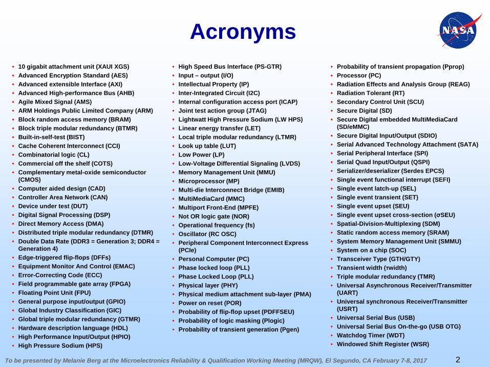
Acronyms• 10 gigabit attachment unit (XAUI XGS)• Advanced Encryption Standard (AES)• Advanced extensible Interface (AXI)• Advanced High-performance Bus (AHB)• Agile Mixed Signal (AMS)• ARM Holdings Public Limited Company (ARM)• Block random access memory (BRAM)• Block triple modular redundancy (BTMR)• Built-in-self-test (BIST)• Cache Coherent Interconnect (CCI)• Combinatorial logic (CL)• Commercial off the shelf (COTS)• Complementary metal-oxide semiconductor
(CMOS)• Computer aided design (CAD)• Controller Area Network (CAN)• Device under test (DUT)• Digital Signal Processing (DSP)• Direct Memory Access (DMA)• Distributed triple modular redundancy (DTMR)• Double Data Rate (DDR3 = Generation 3; DDR4 =
Generation 4)• Edge-triggered flip-flops (DFFs)• Equipment Monitor And Control (EMAC)• Error-Correcting Code (ECC)• Field programmable gate array (FPGA)• Floating Point Unit (FPU)• General purpose input/output (GPIO)• Global Industry Classification (GIC)• Global triple modular redundancy (GTMR)• Hardware description language (HDL)• High Performance Input/Output (HPIO)• High Pressure Sodium (HPS)
2
• High Speed Bus Interface (PS-GTR)• Input – output (I/O)• Intellectual Property (IP)• Inter-Integrated Circuit (I2C)• Internal configuration access port (ICAP) • Joint test action group (JTAG)• Lightwatt High Pressure Sodium (LW HPS)• Linear energy transfer (LET)• Local triple modular redundancy (LTMR)• Look up table (LUT)• Low Power (LP)• Low-Voltage Differential Signaling (LVDS)• Memory Management Unit (MMU)• Microprocessor (MP)• Multi-die Interconnect Bridge (EMIB)• MultiMediaCard (MMC)• Multiport Front-End (MPFE)• Not OR logic gate (NOR)• Operational frequency (fs)• Oscillator (RC OSC)• Peripheral Component Interconnect Express
(PCIe)• Personal Computer (PC)• Phase locked loop (PLL)• Phase Locked Loop (PLL)• Physical layer (PHY)• Physical medium attachment sub-layer (PMA)• Power on reset (POR)• Probability of flip-flop upset (PDFFSEU)• Probability of logic masking (Plogic)• Probability of transient generation (Pgen)
• Probability of transient propagation (Pprop)• Processor (PC)• Radiation Effects and Analysis Group (REAG)• Radiation Tolerant (RT)• Secondary Control Unit (SCU)• Secure Digital (SD)• Secure Digital embedded MultiMediaCard
(SD/eMMC)• Secure Digital Input/Output (SDIO)• Serial Advanced Technology Attachment (SATA)• Serial Peripheral Interface (SPI)• Serial Quad Input/Output (QSPI)• Serializer/deserializer (Serdes EPCS)• Single event functional interrupt (SEFI)• Single event latch-up (SEL)• Single event transient (SET)• Single event upset (SEU)• Single event upset cross-section (σSEU)• Spatial-Division-Multiplexing (SDM)• Static random access memory (SRAM)• System Memory Management Unit (SMMU)• System on a chip (SOC)• Transceiver Type (GTH/GTY)• Transient width (τwidth)• Triple modular redundancy (TMR)• Universal Asynchronous Receiver/Transmitter
(UART)• Universal synchronous Receiver/Transmitter
(USRT)• Universal Serial Bus (USB)• Universal Serial Bus On-the-go (USB OTG)• Watchdog Timer (WDT)• Windowed Shift Register (WSR)
To be presented by Melanie Berg at the Microelectronics Reliability & Qualification Working Meeting (MRQW), El Segundo, CA February 7-8, 2017
Problem Statement
• For many years, intellectual property (IP) cores have been incorporated into field programmable gate array (FPGA) and application specific integrated circuit (ASIC) design flows.
• However, the usage of large complex IP cores were limited within products that required a high level of reliability.
• This is no longer the case. IP core insertion has become mainstream …including their use in highly reliable products.
• Due to limited visibility and control, challenges exist when using IP cores and subsequently compromise product reliability.
3
To be presented by Melanie Berg at the Microelectronics Reliability & Qualification Working Meeting (MRQW), El Segundo, CA February 7-8, 2017
IP Core Terminology Regarding FPGA Insertion
• IP cores are blocks of logic elements:– Reduce Time-to-Market.– Eliminate Design Risks.– Reduce Development Costs.
• IP cores can be “Soft” or “Hard.”– Terminology has nothing to do with radiation
susceptibility.– Soft Core: IP logic blocks are implemented in the
system programmable logic area (user area). They are generally flexible in order to meet user needs.
– Hard Core: IP logic are embedded in the FPGA device. They have limited flexibility or none at all.
4
To be presented by Melanie Berg at the Microelectronics Reliability & Qualification Working Meeting (MRQW), El Segundo, CA February 7-8, 2017
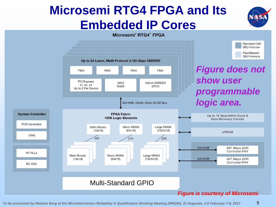
Microsemi RTG4 FPGA and Its Embedded IP Cores
5
Figure is courtesy of Microsemi
Figure does not show user programmable logic area.
Multi-Standard GPIO
To be presented by Melanie Berg at the Microelectronics Reliability & Qualification Working Meeting (MRQW), El Segundo, CA February 7-8, 2017
Soft IP Core Insertion Flow
6
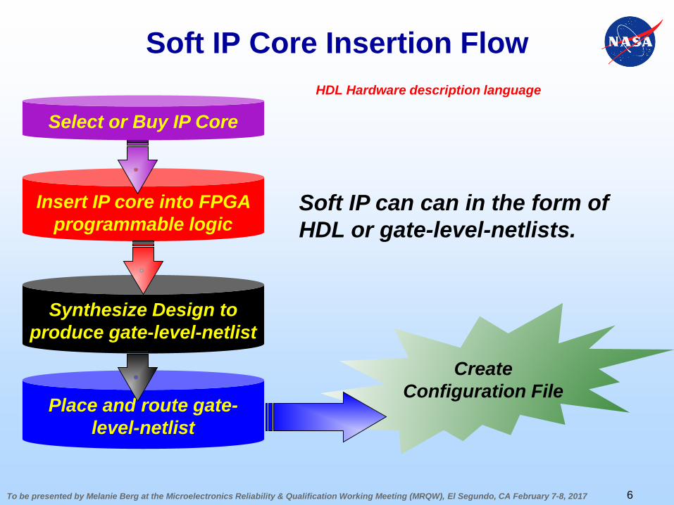
Select or Buy IP Core
Insert IP core into FPGA programmable logic
Synthesize Design to produce gate-level-netlist
Place and route gate-level-netlist
Create Configuration File
Soft IP can can in the form of HDL or gate-level-netlists.
HDL Hardware description language
To be presented by Melanie Berg at the Microelectronics Reliability & Qualification Working Meeting (MRQW), El Segundo, CA February 7-8, 2017
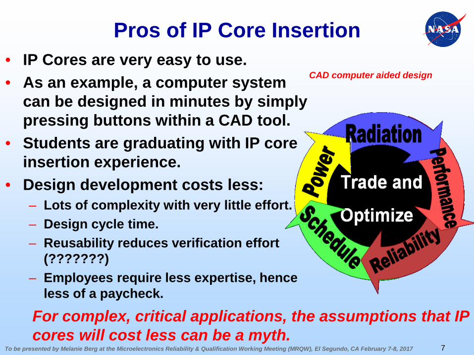
Pros of IP Core Insertion • IP Cores are very easy to use.• As an example, a computer system
can be designed in minutes by simply pressing buttons within a CAD tool.
• Students are graduating with IP core insertion experience.
• Design development costs less:– Lots of complexity with very little effort.– Design cycle time.– Reusability reduces verification effort
(???????)– Employees require less expertise, hence
less of a paycheck.
7
CAD computer aided design
For complex, critical applications, the assumptions that IP cores will cost less can be a myth.
To be presented by Melanie Berg at the Microelectronics Reliability & Qualification Working Meeting (MRQW), El Segundo, CA February 7-8, 2017
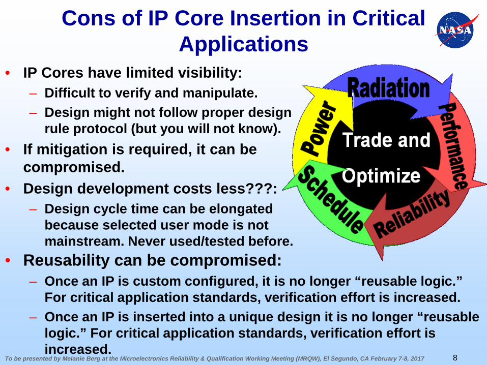
Cons of IP Core Insertion in Critical Applications
• IP Cores have limited visibility:– Difficult to verify and manipulate.– Design might not follow proper design
rule protocol (but you will not know).• If mitigation is required, it can be
compromised.• Design development costs less???:
– Design cycle time can be elongated because selected user mode is not mainstream. Never used/tested before.
8
• Reusability can be compromised:– Once an IP is custom configured, it is no longer “reusable logic.”
For critical application standards, verification effort is increased.– Once an IP is inserted into a unique design it is no longer “reusable
logic.” For critical application standards, verification effort is increased.
To be presented by Melanie Berg at the Microelectronics Reliability & Qualification Working Meeting (MRQW), El Segundo, CA February 7-8, 2017
Challenges: IP Core Insertion in Critical Applications
• Beware – pushing a button on a CAD tool can be misleading.
• Does the core follow proper synchronous design methodology?
• How has the design been vetted and verified prior to your usage?
• Research must be performed in order to understand if the IP can reliably be inserted into your design:– Timing characteristics – can the IP perform at the missions
specified speed?– Can the IP core fit into the device with all other necessary
logic?– Are the I/O of the IP compatible with your device or the other
components you have in your device?– Does the IP require mitigation?
9
To be presented by Melanie Berg at the Microelectronics Reliability & Qualification Working Meeting (MRQW), El Segundo, CA February 7-8, 2017
Challenges: IP Core Verification in Critical Applications
• Design reviews require design to be parsed by a team of specialists. – Some IP cores are so complex, they are close to impossible
to parse.– Some IP cores are in gate-netlist form instead of HDL. They
are also close to impossible to parse.– Some IP cores are locked and cannot be viewed by any
individual.• Although datasheets are available, users will rely on
IP core models and blind testing.• Point is, because of limited visibility and complexity,
IP are hard to verify.
10
• Enhanced verification techniques exist but still have limitations regarding black box (like) IP.
To be presented by Melanie Berg at the Microelectronics Reliability & Qualification Working Meeting (MRQW), El Segundo, CA February 7-8, 2017
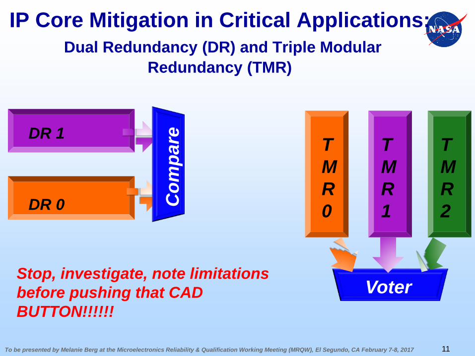
IP Core Mitigation in Critical Applications:Dual Redundancy (DR) and Triple Modular
Redundancy (TMR)
11
TMR 0
TMR 1
TMR 2
Voter
Com
pareDR 1
DR 0
Stop, investigate, note limitations before pushing that CAD BUTTON!!!!!!
To be presented by Melanie Berg at the Microelectronics Reliability & Qualification Working Meeting (MRQW), El Segundo, CA February 7-8, 2017
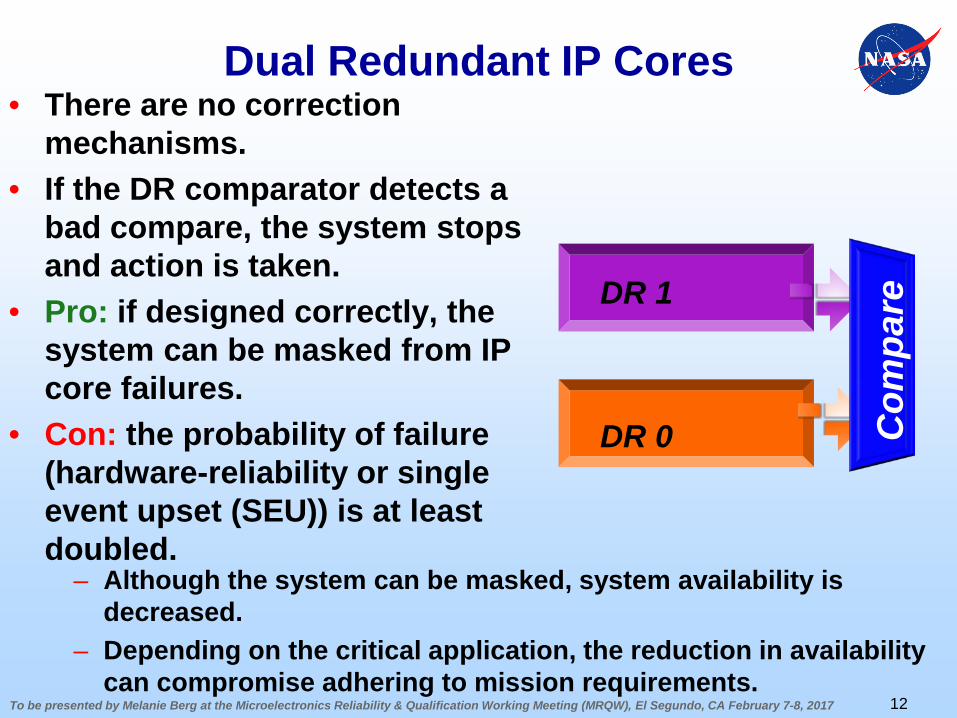
Dual Redundant IP Cores• There are no correction
mechanisms. • If the DR comparator detects a
bad compare, the system stops and action is taken.
• Pro: if designed correctly, the system can be masked from IP core failures.
• Con: the probability of failure (hardware-reliability or single event upset (SEU)) is at least doubled.
12
Com
pareDR 1
DR 0
– Although the system can be masked, system availability is decreased.
– Depending on the critical application, the reduction in availability can compromise adhering to mission requirements.
To be presented by Melanie Berg at the Microelectronics Reliability & Qualification Working Meeting (MRQW), El Segundo, CA February 7-8, 2017
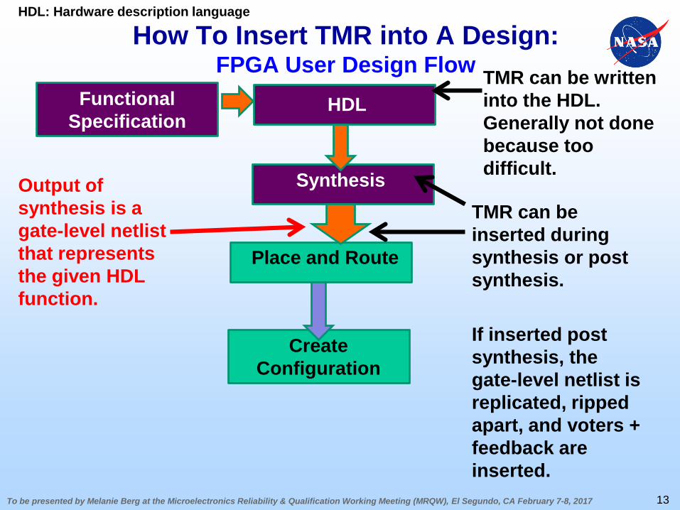
How To Insert TMR into A Design:FPGA User Design Flow
Create Configuration
Place and Route
Output of synthesis is a gate-level netlistthat represents the given HDL function.
Functional Specification
HDL
Synthesis
HDL: Hardware description language
13
TMR can be inserted during synthesis or post synthesis.
If inserted post synthesis, the gate-level netlist is replicated, ripped apart, and voters + feedback are inserted.
TMR can be written into the HDL. Generally not done because too difficult.
To be presented by Melanie Berg at the Microelectronics Reliability & Qualification Working Meeting (MRQW), El Segundo, CA February 7-8, 2017
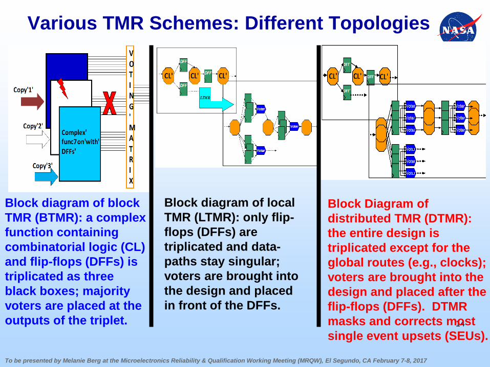
Various TMR Schemes: Different Topologies
14
Block diagram of block TMR (BTMR): a complex function containing combinatorial logic (CL) and flip-flops (DFFs) is triplicated as three black boxes; majority voters are placed at the outputs of the triplet.
Block diagram of local TMR (LTMR): only flip-flops (DFFs) are triplicated and data-paths stay singular; voters are brought into the design and placed in front of the DFFs.
Block Diagram of distributed TMR (DTMR): the entire design is triplicated except for the global routes (e.g., clocks); voters are brought into the design and placed after the flip-flops (DFFs). DTMR masks and corrects most single event upsets (SEUs).
To be presented by Melanie Berg at the Microelectronics Reliability & Qualification Working Meeting (MRQW), El Segundo, CA February 7-8, 2017
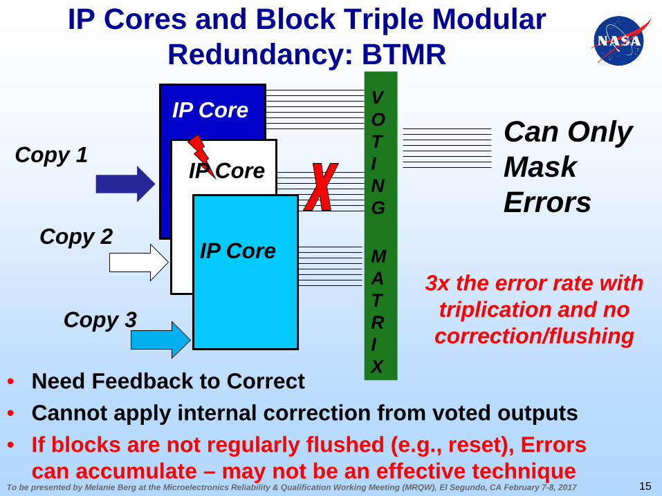
IP Cores and Block Triple Modular Redundancy: BTMR
• Need Feedback to Correct• Cannot apply internal correction from voted outputs• If blocks are not regularly flushed (e.g., reset), Errors
can accumulate – may not be an effective technique
VOTING
MATRIX
IP Core
Can Only Mask Errors
3x the error rate with triplication and no correction/flushing
Copy 1
Copy 2
Copy 3
15
IP Core
IP Core
To be presented by Melanie Berg at the Microelectronics Reliability & Qualification Working Meeting (MRQW), El Segundo, CA February 7-8, 2017
00.10.20.30.40.50.60.70.80.9
1
0 5000 10000
Rel
iabi
lity
Minutes
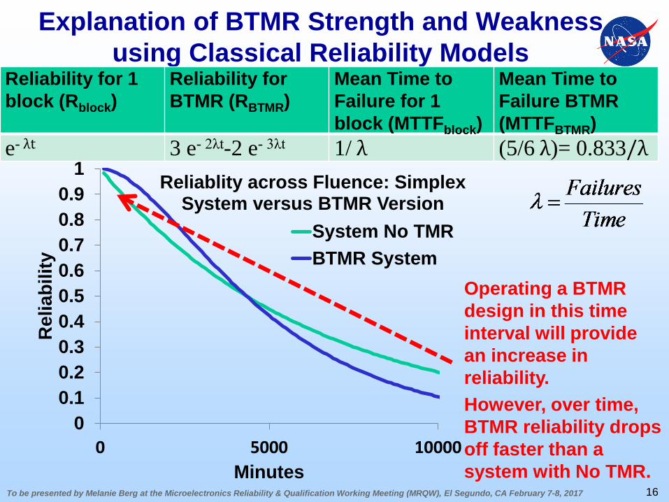
Reliablity across Fluence: Simplex System versus BTMR Version
System No TMRBTMR System
Explanation of BTMR Strength and Weakness using Classical Reliability Models
Operating a BTMR design in this time interval will provide an increase in reliability.However, over time, BTMR reliability drops off faster than a system with No TMR.
16
Reliability for 1 block (Rblock)
Reliability for BTMR (RBTMR)
Mean Time to Failure for 1 block (MTTFblock)
Mean Time to Failure BTMR (MTTFBTMR)
e- λt 3 e- 2λt-2 e- 3λt 1/ λ (5/6 λ)= 0.833/λ
To be presented by Melanie Berg at the Microelectronics Reliability & Qualification Working Meeting (MRQW), El Segundo, CA February 7-8, 2017
BTMR Bottom Line
• How long does your BTMR system need to operate relative to the MTTF for one of its unmitigated blocks?
• Over time, a BTMR system is less reliable than an unmitigated system.
• Adding more replicated blocks (e.g., N-out-of-M) system will only increase the reliability during the short window near start time. However, overtime, the reliability of an N-out-of-M system will fall faster as M (the number of replicated blocks) grows.
• Unfortunately BTMR is the most common means of TMR used with IP cores. Users are not getting the level of protection that they require.
17
To be presented by Melanie Berg at the Microelectronics Reliability & Qualification Working Meeting (MRQW), El Segundo, CA February 7-8, 2017
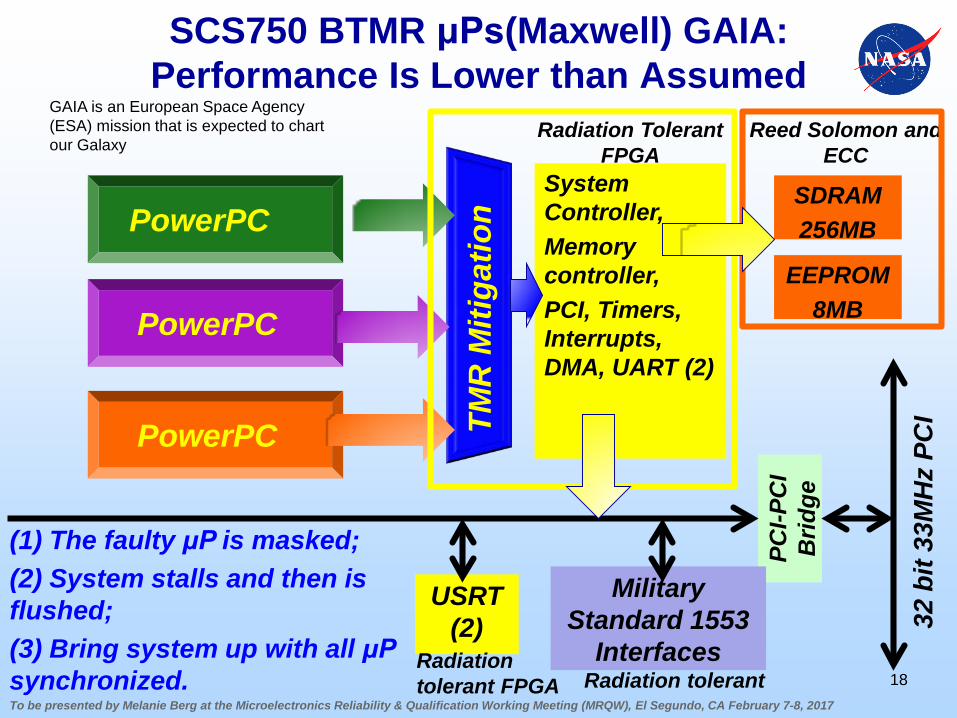
SCS750 BTMR μPs(Maxwell) GAIA: Performance Is Lower than Assumed
18
TMR
Miti
gatio
n
System Controller,Memory controller, PCI, Timers, Interrupts, DMA, UART (2)
SDRAM256MB
EEPROM8MB
PCI-P
CI
Brid
ge
Reed Solomon and ECC
Radiation Tolerant FPGA
32 b
it 33
MH
z PC
I
USRT (2)
Military Standard 1553
InterfacesRadiation tolerant FPGA Radiation tolerant
GAIA is an European Space Agency (ESA) mission that is expected to chart our Galaxy
PowerPC
PowerPC
PowerPC
(1) The faulty μP is masked; (2) System stalls and then is flushed;(3) Bring system up with all μPsynchronized.
To be presented by Melanie Berg at the Microelectronics Reliability & Qualification Working Meeting (MRQW), El Segundo, CA February 7-8, 2017
DTMR and LTMR Strategies Provide Correction and Hence Increase
Availability and Reliability• Depending on the target FPGA, DTMR or LTMR can be
suitable mitigation strategies:– LTMR for Microsemi FPGA products (Do not use in SRAM
based FPGAs)– DTMR for SRAM based FPGA products (e.g., Xilinx).
• Depending on your TMR insertion tool , some IP cores can have LTMR or DTMR inserted during the synthesis process.
• Most tools are still having problems with TMR insertion into IP. This is another reason why BTMR is so popular… it’s simple to implement.
• Warning, there are some IP cores that are black boxes and no tool can insert LTMR or DTMR.
19
Concerns to be taken into account prior to IP selection.
To be presented by Melanie Berg at the Microelectronics Reliability & Qualification Working Meeting (MRQW), El Segundo, CA February 7-8, 2017
Acknowledgements
• Some of this work has been sponsored by the NASA Electronic Parts and Packaging (NEPP) Program and the Defense Threat Reduction Agency (DTRA).
• Thanks is given to the NASA Goddard Radiation Effects and Analysis Group (REAG) for their technical assistance and support. REAG is led by Kenneth LaBel and Jonathan Pellish.
20
Contact Information:Melanie Berg: NASA Goddard REAG FPGA
Principal Investigator:[email protected]