Embed Size (px)
Citation preview

■ Please read this manual and the enclosed safety materials carefully!
■ Fasten the manual near the garage door after installation.
■ The door WILL NOT CLOSE unless the Protector System® is connected and properly aligned.
■ Periodic checks of the garage door opener are required to ensure safe operation.
■ The model number label is located on the left side panel of your garage door opener.
■ This garage door opener is compatible with MyQ® and Security+ 2.0®
accessories.
■ DO NOT install on a one-piece door if using devices or features providing unattended close. Unattended devices and features are to be used ONLY with sectional doors.
CONTENTSPreparation . . . . . . . . . . . . . . . .1-4
Assembly . . . . . . . . . . . . . . . . .5-8
Installation . . . . . . . . . . . . . . . 9-26
Adjustments . . . . . . . . . . . . . 27-29
Battery Backup. . . . . . . . . . . . . . 30
MyQ® Smartphone ControlGet Connected . . . . . . . . . . . . . . 31
Operation . . . . . . . . . . . . . . . 32-36
Maintenance . . . . . . . . . . . . . . . 37
Troubleshooting. . . . . . . . . . . 38-39
Accessories. . . . . . . . . . . . . . . . 40
Warranty. . . . . . . . . . . . . . . . . . 41
Repair Parts . . . . . . . . . . . . . 42-43
1-1/4 hps* Belt Drive Garage Door Opener with MyQ® Smartphone Control and Battery Backup
The Chamberlain Group, Inc.845 Larch Avenue
Elmhurst, Illinois 60126-1196
www.chamberlain.comwww.mychamberlain.com
Models • WD1000WF • HD950WF • LW9000WFFOR RESIDENTIAL USE ONLY
* Horsepower similar (hps) designates that this garage door opener system meets Chamberlain’s pulling force specification for a 1-1/4 horsepower garage door opener.
Write down the MyQ® serial number located on the garage door opener:

1
Safety Symbol and Signal Word ReviewThis garage door opener has been designed and tested to offer safe service provided it is installed,operated,maintained and tested in strict accordance with the instructions and warnings contained in thismanual.When you see these Safety Symbols and Signal Words on the following pages, they will alert you to thepossibility of serious injury or death if you do not comply with the warnings that accompany them. Thehazard may come from something mechanical or from electric shock. Read the warnings carefully.
Mechanical
Electrical
When you see this Signal Word on the following pages, it will alert you to the possibility of damage toyour garage door and/or the garage door opener if you do not comply with the cautionary statements thataccompany it. Read them carefully.
Unattended OperationThe Timer-to-Close (TTC) feature, the MyQ®Smartphone Control app, and MyQ®Garage Door andGate Monitor are examples of unattended close and are to be used ONLY with sectional doors. Anydevice or feature that allows the door to close without being in the line of sight of the door is consideredunattended close. The Timer-to-Close (TTC) feature, the MyQ®Smartphone Control, and any otherMyQ® devices are to be used ONLY with sectional doors.The Timer-to-Close (TTC) feature is an example of unattended close to be used ONLY with sectionaldoors. Any device or feature that allows the door to close without being in the line of sight of the door isconsidered unattended close. The Timer-to-Close (TTC) feature and any other devices that allowunattended operation are to be used ONLY with sectional doors.
Check the Door
To prevent possible SERIOUS INJURY or DEATH:l ALWAYS call a trained door systems technician if garage door binds, sticks, or is out of balance.
An unbalanced garage door mayNOT reverse when required.l NEVER try to loosen,move or adjust garage door, door springs, cables, pulleys, brackets or their
hardware, ALL of which are under EXTREME tension.l Disable ALL locks and remove ALL ropes connected to garage door BEFORE installation and
operating garage door opener to avoid entanglement.l DO NOT install on a one-piece door if using devices or features providing unattended close.
Unattended devices and features are to be used ONLY with sectional doors.
To prevent damage to garage door and opener:l ALWAYS disable locks BEFORE installing and operating the opener.l ONLY operate garage door opener at 120 V, 60 Hz to avoid malfunction and damage.
Before you begin:1. Disable locks and remove any ropes connected to the garage door.2. Lift the door halfway up. Release the door. If balanced, it should stay
in place, supported entirely by its springs.3. Raise and lower the door to check for binding or sticking. If your door
binds, sticks, or is out of balance, call a trained door systemstechnician.
4. Check the seal on the bottom of the door. Any gap between the floorand the bottom of the door must not exceed 1/4 inch (6 mm).Otherwise, the safety reversal systemmay not work properly.
5. The opener should be installed above the center of the door. If thereis a torsion spring or center bearing plate in the way of the headerbracket, it may be installed within 4 feet (1.2 m) to the left or right ofthe door center. See page 10.
Torsion
SpringExtension
SpringOR
Preparation

2
Test the Wi-Fi® Signal Strength in your garageYou will need a router with Wi-Fi and a smartphone or other mobile device.Make sure your mobiledevice is connected to your Wi-Fi network. Hold your mobile device in the place where your garage dooropener will be installed and check the Wi-Fi signal strength.
Wi-Fi signal is weak. The garage door opener will likely connect to your Wi-Fi network. If not, try one of the options below.
No Wi-Fi signal. Try one of the following:• Move your router closer to the garage door opener to minimize interference from walls and other objects• Buy a Chamberlain MyQ® Internet Gateway (CIGBU) see page 40• Buy a Wi-Fi range extender
Check Signal Strength. If you see:
Wi-Fi signal is strong. You’re all set!Install your new garage door opener.
Visit wifihelp.chamberlain.com for more details
See MyQ®Smartphone Control page 31 to connect your garage door opener to your Wi-Fi network.
Additional Items You May Need:Survey your garage area to see if you will need any of the following items:
l (2) 2X4 Pieces of wood :May be used to fasten the header bracket to the structural supports.Also used to position the garage door opener during installation and for testing the safetyreversing sensors.
l Support bracket and fastening hardware:Must be used if you have a finished ceiling in yourgarage.
l Extension brackets (MODEL 041A5281-1) orwood blocks: Depending upon garageconstruction, extension brackets or wood blocksmay be needed to install the safety reversingsensor.
l Fastening hardware: Alternate floor mounting of the safety reversing sensor will requirehardware not provided.
l Door reinforcement: Required if you have a lightweight steel, aluminum, fiberglass or glasspanel door.
l Rail extension kit: Required if your garage door ismore than 7 feet (2.13 m) high.
Tools Needed
3/16
7/16
1/2
5/32
5/16
5/8
9/16
1/4
7/16
Preparation

3
Carton InventoryYour garage door opener is packaged in one carton which contains the motor unit and all partsillustrated below. Accessories vary depending on the garage door opener model purchased. Dependingon your model, other accessoriesmay be included with your garage door opener. Instructions for theseaccessories will be attached to the accessory and are not included in thismanual. Save the carton andpacking material until the installation and adjustment is complete. The images throughout thismanualare for reference only and your productmay look different.
A. Header bracketB. PulleyC. Door bracketD. Curved door armE. Straight door arm
(Packaged inside front rail section)F. Trolley
NOTE: Be sure to assemble the trolley before sliding onto rail.G. Emergency release rope and handleH. Rail (1 front and 4 center sections)I. Hanging brackets (2)
(Packaged inside the front rail section)J. Garage door opener (motor unit)K. Sprocket cover and screwsL. “U” bracketM. BeltN. Door control (Smart Control Panel®)O. Remote control (2)P. The Protector System®
Safety reversing sensors with 2 conductor white and white/black wire attached: Sending Sensor(1), Receiving Sensor (1), and Safety Sensor Brackets (2)
NOTSHOWNWhite and red/white wireOwner'smanualHardware
Preparation

4
Hardware
Clevis Pin 5/16"x1-1/2"
Ring Fastener (3)
Hex Bolt 5/16"-18x7/8" (4)
Lock Washer 5/16"-18 (5)Nut
5/16"-18 (6)
Self-Threading Screw 1/4"-14x5/8" (2)
Clevis Pin 5/16"x1"Clevis Pin 5/16"x1-1/4"
Carriage Bolt 1/4"-20x1/2" (2)
Wing Nut 1/4"-20 (2)
ASSEMBLY INSTALLATION
Screw 6ABx1" (2) Drywall Anchors (2)
Screw 6-32x1" (2)
DOOR CONTROL
Insulated Staples(Not Shown)
Lag Screw 5/16"-9x1-5/8" (4)
Hex Screw #8x3/8" (3)(packed with the sprocket cover)
Bolt 1/4"-20x1-3/4"
Lock Nut 1/4"-20
Bolt
Nut 3/8"
Lock Washer 3/8"
Master Link
Spring Trolley Nut
Threaded Shaftwith
Preparation

5
AssemblySTEP 1 Assemble the rail and install the trolley
To prevent INJURY from pinching, keep hands and fingers away from the joints while assembling therail.
To avoid installation difficulties, do not run the garage door opener until instructed to do so.The front rail has a cut out “window” at the door end. The rail tab MUST be on top of the rail whenassembled.
1. Remove the straight door arm and hanging bracket packaged inside the front rail and set asidefor Installation Step 5 and 9.NOTE: To prevent INJURY while unpacking the rail carefully removethe straight door arm stored within the rail section.
2. Align the rail sections on a flat surface as shown and slide the tapered ends into the larger ones.Tabs along the side will lock into place.
3. Place the motor unit on packing material to protect the cover, and rest the back end of the rail ontop. For convenience, put a support under the front end of the rail.
4. As a temporary stop, insert a screwdriver into the hole in the second rail section from the motorunit, as shown.
5. Check to be sure there are 4 plastic wear pads inside the inner trolley. If they became looseduring shipping, check all packing material. Snap them back into position as shown.
6. Slide the trolley assembly toward the screwdriver as shown.7. Slide the rail onto the “U” bracket, until it reaches all the stops on the top and sides of the “U”
bracket.
To garagedoor opener
(TO MOTOR UNIT)
Front RailSection(TO DOOR)
“U” Bracket
Outer Trolley
Inner Trolley
Wear Pads
SLIDE TO STOPSON TOP AND SIDES OF “U” BRACKET
Trolley
Rail Tab

6
AssemblySTEP 2 Fasten the rail to the motor unit
To avoid SERIOUS damage to garage door opener, use ONLY those bolts/fastenersmounted in thetop of the opener.
1. Insert a 1/4"-20x1-3/4" bolt into the cover protection bolt hole on the back end of the rail asshown. Tighten securely with a 1/4"-20 lock nut. DO NOT overtighten.
2. Remove the bolts from the top of the motor unit.3. Use the carton to support the front end of the rail.4. Place the “U” bracket, flat side down onto the motor unit and align the bracket holes with the bolt
holes.5. Fasten the “U” bracket with the previously removed bolts; DO NOT use any power tools. The use
of power toolsmay permanently damage the garage door opener.
“U” Bracket
Cover Protection Bolt Hole
Bolt 1/4"-20x1-3/4"
Lock Nut 1/4"-20
Bolts (Mounted in the garage door opener)
HARDWARE
Bolt 1/4"-20x1-3/4"
Lock Nut 1/4"-20
STEP 3 Install the idler pulley1. Lay the belt beside the rail, as shown.Grasp the end with the hooked trolley connector and pass
approximately 12" (30 cm) of belt through the window. Keep the ribbed side toward the rail, andallow it to hang until Assembly Step 4.
2. Remove the tape from the idler pulley. The inside center should be pre-greased. If dry, regreaseto ensure proper operation.
3. Place the idler pulley into the window as shown.4. Insert the idler bolt from the top through the rail and pulley. Tighten with a 3/8" lock washer and
nut underneath the rail until the lock washer is compressed.5. Rotate the pulley to be sure it spins freely.6. Locate the rail tab. The rail tab is between the idler bolt and the trolley in the front rail section. Use
a flathead screwdriver and lift the rail tab until the tab is vertical (90º).
Rail
Trolley Connector
Bolt
Lock Washer 3/8"
Nut 3/8"
Rail Tab
CORRECT INCORRECT
Idler Pulley
Grease Inside Pulley
HARDWARE
Bolt Nut 3/8"Lock Washer 3/8"
Rail Tab

7
AssemblySTEP 4 Install the belt
1. Pull the belt around the idler pulley and toward the trolley. The ribbed side must contact thepulley.
2. Hook the trolley connector into the retaining slot on the trolley as shown (Figure 1).3. With the trolley against the screwdriver, dispense the remainder of the belt along the rail
length toward the motor unit and around the sprocket (Figure 2). The sprocket teeth must engagethe belt.
4. Check to make sure the belt is not twisted. Connect the trolley threaded shaft with the master link (Figure 3).l Push pins ofmaster link bar through holes in end of belt and trolley threaded shaft.l Push master link cap over pins and past pin notches.l Slide the closed end of the clip-on spring over one of the pins. Push the open end of the
clip-on spring onto the other pin.5. Remove the spring trolley nut from the threaded shaft.6. Insert the trolley threaded shaft through the hole in the trolley.
HARDWARE
Master Link
Threaded Shaft with Spring Trolley Nut
Sprocket
Figure 3
Threaded Shaft
Master Link
Figure 2
Trolley Connector
Figure 1
Retaining
Slot
8
AssemblySTEP 5 Tighten the belt
1. By hand, thread the spring trolley nut on the threaded shaft until it is finger tight against thetrolley. Do not use any tools. Remove the screwdriver.
2. Insert a flathead screwdriver tip into one of the nut ring slots and brace it firmly against the trolley.3. Tighten the spring trolley nut with an adjustable wrench or a 7/16" open end wrench about a
quarter turn until the spring releases and snaps the nut ring against the trolley. This sets thespring to optimum belt tension.
Nut Ring
BEFORE1"
(2.5 cm)
Nut Ring
AFTER1-1/4"
(3.18 cm)
SpringTrolley Nut
Nut Ring Slot
STEP 6 Install the sprocket cover
To avoid possible SERIOUS INJURY to finger frommoving garage door opener:l ALWAYS keep hand clear of sprocket while operating opener.l Securely attach sprocket cover BEFORE operating.
1. Position the sprocket cover over the sprocket as shown and fasten to the mounting plate with8x3/8" hex screws provided.
You have now finished assembling your garage door opener. Please read the followingwarningsbefore proceeding to the installation section.
Hex Screw #8x3/8"(Packed with the sprocket cover)
HARDWARE
Hex Screw #8x3/8"
Sprocket Cover

9
Installation
IMPORTANT INSTALLATION INSTRUCTIONS
To reduce the risk of SEVERE INJURY or DEATH:1. READANDFOLLOWALL INSTALLATIONWARNINGS AND INSTRUCTIONS.2. Install garage door opener ONLY on properly balanced and lubricated garage door. An
improperly balanced door mayNOT reverse when required and could result in SEVEREINJURY or DEATH.
3. ALL repairs to cables, spring assemblies and other hardware MUST be made by a trained doorsystems technician BEFORE installing opener.
4. Disable ALL locks and remove ALL ropes connected to garage door BEFORE installing openerto avoid entanglement.
5. Install garage door opener 7 feet (2.13 m) or more above floor.6. Mount the emergency release within reach, but at least 6 feet (1.83 m) above the floor and
avoiding contact with vehicles to avoid accidental release.7. NEVER connect garage door opener to power source until instructed to do so.8. NEVERwear watches, rings or loose clothing while installing or servicing opener. They could be
caught in garage door or opener mechanisms.
9. Install wall-mounted garage door control:l within sight of the garage door.l out of reach of children atminimum height of 5 feet (1.5 m).l away fromALL moving parts of the door.
10. Place entrapment warning label on wall next to garage door control.11. Place manual release/safety reverse test label in plain view on inside of garage door.12. Upon completion of installation, test safety reversal system. Door MUST reverse on contact with a
1-1/2" (3.8 cm) high object (or a 2x4 laid flat) on the floor.13. To avoid SERIOUS PERSONAL INJURY or DEATH from electrocution, disconnect ALL electric
and battery power BEFORE performing ANY service or maintenance.14. DO NOT install on a one-piece door if using devices or features providing unattended close.
Unattended devices and features are to be used ONLY with sectional doors.
10
InstallationSTEP 1 Determine the header bracket location
To prevent possible SERIOUS INJURY or DEATH:l Header bracketMUST be RIGIDLY fastened to structural support on header wall or ceiling,
otherwise garage door might NOT reverse when required. DO NOT install header bracket overdrywall.
l Concrete anchorsMUST be used if mounting header bracket or 2x4 into masonry.l NEVER try to loosen,move or adjust garage door, springs, cables, pulleys, brackets, or their
hardware, ALL of which are under EXTREME tension.l ALWAYS call a trained door systems technician if garage door binds, sticks, or is out of balance.
An unbalanced garage door might NOT reverse when required.
Installation procedures vary according to garage door types. Follow the instructions which apply to yourdoor.
1. Close the door and mark the inside vertical centerline of the garage door.2. Extend the line onto the header wall above the door.You can fasten the header bracket within 4
feet (1.22 m) of the left or right of the door center only if a torsion spring or center bearing plate isin the way; or you can attach it to the ceiling (see page 11) when clearance isminimal. (It may bemounted on the wall upside down if necessary, to gain approximately 1/2" (1 cm). If you need toinstall the header bracket on a 2x4 (on wall or ceiling), use lag screws (not provided) to securelyfasten the 2x4 to structural supports as shown here and on page 11.
3. Open your door to the highest point of travel as shown. Draw an intersecting horizontal line onthe header wall 2" (5 cm) above the high point :
l 2" (5 cm) above the high point for sectional door and one-piece door with track.l 8" (20 cm) above the high point for one-piece door without track.
This height will provide travel clearance for the top edge of the door.NOTE: If the total number of inchesexceeds the height available in your garage, use the maximum height possible, or refer to page 11 forceiling installation.
Header WallVertical Centerline of Garage Door
2x4 Structural Supports
Level
(Optional)
Unfinished Ceiling
2x4
OPTIONAL CEILING MOUNT FOR HEADER BRACKET
Sectional door with curved track
Header Wall
Track
2" (5 cm)
Highest Point of Travel
Door
One-piece door with horizontal track
Header Wall
Track
2" (5 cm)
Highest
Point of
Travel
Door
One-piece door without track:jamb hardware
Header Wall
8" (20 cm)
Highest
Point of
Travel
Door
Jamb Hardware
One-piece door without track:pivot hardware
Header Wall8" (20 cm)
Highest
Point of
Travel
Door
Pivot

11
InstallationSTEP 2 Install the header bracketYou can attach the header bracket either to the wall above the garage door, or to the ceiling. Follow theinstructions which will work best for your particular requirements. Do not install the header bracket overdrywall. If installing into masonry, use concrete anchors (not provided).
HARDWARE
Lag Screw 5/16"-9x1-5/8"
OPTION AWALL INSTALLATION1. Center the bracket on the vertical centerline with the bottom edge of the bracket on the horizontal
line as shown (with the arrow pointing toward the ceiling).2. Mark the vertical set of bracket holes. Drill 3/16" pilot holes and fasten the bracket securely to a
structural support with the hardware provided.
UP
Wall Mount
Optional Mounting Holes
Vertical
Centerline of
Garage Door
(Header Wall)
Header
Bracket
2x4 Structural
Support
Door Spring
(Garage Door)
Highest Point of Garage Door Travel
HorizontalLine
Lag Screw
5/16"-9x1-5/8"
OPTION B CEILING INSTALLATION1. Extend the vertical centerline onto the ceiling as shown.2. Center the bracket on the vertical mark, no more than 6" (15 cm) from the wall. Make sure the
arrow is pointing away from the wall. The bracket can be mounted flush against the ceiling whenclearance isminimal.
3. Mark the side holes. Drill 3/16" pilot holes and fasten bracket securely to a structural support withthe hardware provided.
UP
(Header Wall)
Ceiling Mounting
Holes (Finished Ceiling)
Vertical
Centerline of
Garage Door
Header
Bracket
6" (15 cm)
Maximum
Door Spring
(Garage Door)
Lag Screw
5/16"-9x1-5/8"

12
InstallationSTEP 3 Attach the rail to the header bracket
1. Position the opener on the garage floor below the header bracket. Use packing material as aprotective base.NOTE: If the door spring is in the way, you will need help. Have someone hold the openersecurely on a temporary support to allow the rail to clear the spring.
2. Position the rail bracket against the header bracket.3. Align the bracket holes and join with a clevis pin as shown.4. Insert a ring fastener to secure.
HARDWARE
Clevis Pin 5/16"x1-1/2" Ring Fastener
Clevis Pin
5/16"x1-1/2"
Ring Fastener
STEP 4 Position the garage door opener
To prevent damage to garage door, rest garage door opener rail on 2x4 placed on top section of door.
1. Remove the packing material and lift the garage door opener onto a ladder.2. Fully open the door and place a 2x4 (laid flat) under the rail. For one-piece doors without tracks,
lay the 2x4 on it's side.NOTE: A 2x4 is ideal for setting the distance between the rail and the door. If the ladder is not tallenough you will need help at this point. If the door hits the trolley when it is raised, pull the trolley releasearm down to disconnect the inner and outer trolley. Slide the outer trolley toward the garage dooropener. The trolley can remain disconnected until instructed.
One-piece door without tracks
All other door types
Connected Disconnected
13
InstallationSTEP 5 Hang the garage door opener
To avoid possible SERIOUS INJURY from a falling garage door opener, fasten it SECURELY tostructural supports of the garage. Concrete anchorsMUST be used if installing ANY brackets intomasonry.
Hanging the garage door opener will vary depending on your garage. Below are three exampleinstallations. Your installation may be different. For ALL installations the garage door opener MUST beconnected to structural supports. The instructions illustrate one of the examples below.
Finished
Ceiling
Unfinished
Ceiling
HARDWARE
Hex Bolt 5/16"- 18x7/8"
Nut 5/16"-18
Lock Washer 5/16"-18
Lag Screw 5/16"-9x1-5/8"
1. On finished ceilings, use the lag screws to attach a support bracket (not provided) to the structuralsupports before installing the garage door opener.
2. Make sure the garage door opener is aligned with the header bracket. Measure the distancefrom each side of the garage door opener to the support bracket.
3. Cut both pieces of the hanging bracket to required lengths.4. Attach the end of each hanging bracket to the support bracket with appropriate hardware (not
provided).5. Attach the garage door opener to the hanging brackets with the hex bolts, lock washers, and
nuts.6. Remove the 2x4 and manually close the door. If the door hits the rail, raise the header bracket.
Finished Ceiling
(not provided)(not provided)
Lag Screw 5/16"- 9x1-5/8"
Lag Screw 5/16"- 9x1-5/8"
1 2 3
(not provided)
Hex Bolt 5/16"- 18x7/8"
Nut 5/16"-18
Lock Washer 5/16"-18
4 5 6

14
InstallationSTEP 6 Install the light bulbs
To prevent possible OVERHEATING of the end panel or light socket:l Use ONLY A19 incandescent (100Wmaximum) or compact fluorescent (26Wmaximum) light
bulbs.l DO NOT use incandescent bulbs larger than 100W.l DO NOT use compact fluorescent light bulbs larger than 26W (100W) equivalent.l DO NOT use halogen bulbs.l DO NOT use short neck or specialty light bulbs.
1. Pull on the top sides of the light lens and rotate the light lens down.2. Insert an A19 incandescent (100Wmaximum) or compact fluorescent (26W, 100W equivalent)
light bulb into the light socket.3. Rotate the lens up to close.
NOTE: Do not use halogen, short neck, or specialty light bulbs as these may overheat the end panel orlight socket. Do not use LED bulbs as theymay reduce the range or performance of your remote controls.
oror
STEP 7 Attach the emergency release rope and handle
To prevent possible SERIOUS INJURY or DEATH from a falling garage door:l If possible, use emergency release handle to disengage trolleyONLY when garage door is
CLOSED.Weak or broken springs or unbalanced door could result in an open door fallingrapidly and/or unexpectedly.
l NEVER use emergency release handle unless garage doorway is clear of persons andobstructions.
l NEVER use handle to pull door open or closed. If rope knot becomes untied, you could fall.
1. Insert one end of the emergency release rope through the handle.Make sure that “NOTICE” isright side up. Tie a knot at least 1 inch (2.5 cm) from the end of the emergency release rope.
2. Insert the other end of the emergency release rope through the hole in the trolley release arm.Mount the emergency release within reach, but at least 6 feet (1.83 m) above floor, avoidingcontact with vehicles to prevent accidental release and secure with a knot.
NOTE: If it is necessary to cut the emergency release rope, seal the cut end with a match or lighter toprevent unraveling. Ensure the emergency release rope and handle are above the top of all vehicles toavoid entanglement.
15
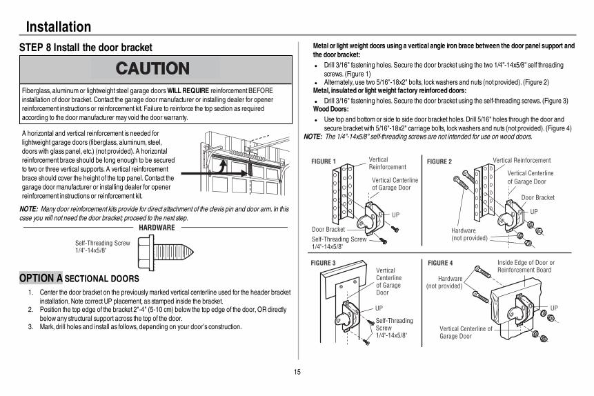
InstallationSTEP 8 Install the door bracket
Fiberglass, aluminum or lightweight steel garage doorsWILLREQUIRE reinforcement BEFOREinstallation of door bracket. Contact the garage door manufacturer or installing dealer for openerreinforcement instructions or reinforcement kit. Failure to reinforce the top section as requiredaccording to the door manufacturer may void the door warranty.
A horizontal and vertical reinforcement is needed forlightweight garage doors (fiberglass, aluminum, steel,doors with glass panel, etc.) (not provided). A horizontalreinforcement brace should be long enough to be securedto two or three vertical supports. A vertical reinforcementbrace should cover the height of the top panel. Contact thegarage door manufacturer or installing dealer for openerreinforcement instructions or reinforcement kit.
NOTE: Many door reinforcement kits provide for direct attachment of the clevis pin and door arm. In thiscase you will not need the door bracket; proceed to the next step.
Self-Threading Screw1/4"-14x5/8"
HARDWARE
OPTION A SECTIONAL DOORS1. Center the door bracket on the previouslymarked vertical centerline used for the header bracket
installation. Note correct UP placement, as stamped inside the bracket.2. Position the top edge of the bracket 2"-4" (5-10 cm) below the top edge of the door, OR directly
below any structural support across the top of the door.3. Mark, drill holes and install as follows, depending on your door’s construction.
Metal or light weight doors using a vertical angle iron brace between the door panel support andthe door bracket:l Drill 3/16" fastening holes. Secure the door bracket using the two 1/4"-14x5/8" self threading
screws. (Figure 1)l Alternately, use two 5/16"-18x2" bolts, lock washers and nuts (not provided). (Figure 2)Metal, insulated or light weight factory reinforced doors:l Drill 3/16" fastening holes. Secure the door bracket using the self-threading screws. (Figure 3)WoodDoors:l Use top and bottom or side to side door bracket holes. Drill 5/16" holes through the door and
secure bracket with 5/16"-18x2" carriage bolts, lock washers and nuts (not provided). (Figure 4)NOTE: The 1/4"-14x5/8" self-threading screws are not intended for use on wood doors.
FIGURE 1
FIGURE 3 FIGURE 4
FIGURE 2Vertical Reinforcement
Vertical Centerline of Garage Door
UP
Door Bracket
Vertical Reinforcement
Vertical Centerline
of Garage Door
Hardware(not provided)
Door Bracket
UP
Vertical Centerlineof Garage Door
UP
Vertical Centerline of Garage Door
Hardware(not provided)
UP
Inside Edge of Door orReinforcement Board
Self-Threading Screw1/4"-14x5/8"
Self-Threading Screw1/4"-14x5/8"

16
InstallationSTEP 8 Install the door bracket (continued)OPTION BONE-PIECE DOORS
1. Center the door bracket on the top of the door, in line with the header bracket as shown.2. Mark either the left and right, or the top and bottom holes.
Metal Doors:l Drill 3/16" pilot holes and fasten the bracket with the self-threading screws provided.
WoodDoors:l Drill 5/16" holes and use 5/16"-18x2" carriage bolts, lock washers and nuts (not provided) or
5/16"x1-1/2" lag screws (not provided) depending on your installation needs.NOTE: The door bracketmay be installed on the top edge of the door if required for your installation.(Refer to the dotted line optional placement drawing.)
For a door with no exposed framing, or for the optional installation, use lag screws 5/16"x1-1/2" (not provided) to fasten the door bracket.
Vertical Centerline of Garage Door
Optional Placement of Door Bracket
Door Bracket
Header Bracket
Header Wall2x4 Support (Finished Ceiling)
DoorBracket
Top of Door (Inside Garage)
Top Edge of Door
Optional
Placement
OptionalPlacement
Top Edgeof Door
Top of Door(Inside Garage)
DoorBracket
Hardware(not provided)
Hardware(not provided)
Metal Door Wood DoorSelf-Threading Screw 1/4"-14x5/8"

17
InstallationSTEP 9 Connect the door arm to the trolleyInstallation will vary according to the garage door type. Follow the instructions which apply to your door.
OPTION A SECTIONAL DOORSIMPORTANT: The groove on the straight door armMUST face away from the curved door arm.
1. Close the door. Disconnect the trolley by pulling the emergency release handle.2. Attach the straight door arm to the outer trolley using the clevis pin. Secure with the ring fastener.3. Attach the curved door arm to the door bracket using the clevis pin. Secure with the ring fastener.4. Bring arm sections together. Find two pairs of holes that line up and join sections. Select holes as
far apart as possible to increase door arm rigidity and attach using the bolts, nuts, and lockwashers.
5. Pull the emergency release handle toward the garage door opener until the trolley release armis horizontal. The trolley will re-engage automatically when the garage door opener is activated.
NOTE: If the holes in the curved door arm and the straight door arm do not align, reverse the straightdoor arm, select two holes (as far apart as possible) and attach using bolts , nuts, and lock washers . If thestraight door arm is hanging down too far, you may cut 6 inches (15 cm) from the solid end.
HARDWARE
Hex Bolt 5/16"-18x7/8"
Nut 5/16"-18 Lock Washer 5/16" -18
Clevis Pin 5/16"x1" Clevis Pin 5/16"x1-1/4"
Ring Fastener
Straight Door Arm Curved
DoorArm
(Groove facing out)
CORRECT
Straight Door Arm Curved
Door Arm
INCORRECT
Lock Washer
5/16" -18
Nut 5/16"-18
Hex Bolt 5/16"-18x7/8"
Clevis Pin 5/16"x1-1/4"
Ring Fastener Clevis Pin 5/16"x1"

18
InstallationSTEP 9 Connect the door arm to the trolley (continued)OPTION BONE-PIECE DOORSIMPORTANT: The groove on the straight door armMUST face away from the curved door arm.
1. Close the door. Disconnect the trolley by pulling the emergency release handle.2. Fasten the straight door arm and the curved door arm together to the longest possible length
(with a 2 or 3 hole overlap) using the bolts, nuts, and lock washers.3. Attach the straight door arm to the door bracket using the clevis pin. Secure with the ring fastener.4. Attach the curved door arm to the trolley using the clevis pin. Secure with the ring fastener.5. Pull the emergency release handle toward the garage door opener until the trolley release arm
is horizontal.HARDWARE
Hex Bolt 5/16"-18x7/8"
Nut 5/16"-18 Lock Washer 5/16" -18
Clevis Pin 5/16"x1" Clevis Pin 5/16"x1-1/4"
Ring Fastener
One-Piece Door without Track
One-Piece Door with Track
Straight Door Arm
Curved DoorArm
(Groove
facing out)
CORRECT INCORRECT
Straight Door Arm
Curved
Door Arm
Ring Fastener
Ring Fastener
Nut 5/16"-18
Nut 5/16"-18
Ring Fastener
Ring Fastener
Lock Washer 5/16" -18
Lock Washer 5/16" -18
Clevis Pin 5/16"x1-1/4"
Clevis Pin 5/16"x1-1/4"
Hex Bolt 5/16"-18x7/8"
Hex Bolt 5/16"-18x7/8"
Clevis Pin 5/16"x1"
Clevis Pin 5/16"x1"

19
InstallationSTEP 10 Install the door control
To prevent possible SERIOUS INJURY or DEATH from electrocution:l Be sure power is NOT connected BEFORE installing door control.l Connect ONLY to 12 VOLT low voltage wires.To prevent possible SERIOUS INJURY or DEATH from a closing garage door:l Install door control within sight of garage door, out of reach of children at a minimum height of 5
feet (1.5 m), and away fromALL moving parts of door.l NEVER permit children to operate or play with door control push buttons or remote control
transmitters.l Activate door ONLY when it can be seen clearly, is properly adjusted, and there are no
obstructions to door travel.l ALWAYS keep garage door in sight until completely closed. NEVER permit anyone to cross path
of closing garage door.
INTRODUCTIONOlder Chamberlain door controls and third party products are not compatible. Install the door controlwithin sight of the door at a minimum height of 5 feet (1.5 m) where small children cannot reach, andaway from the moving parts of the door. For gang box installations it is not necessary to drill holes orinstall the drywall anchors. Use the existing holes in the gang box.NOTE: Your productmay look different than the illustrations.
HARDWARE
Screw6ABx1" (2)
Drywall Anchors (2)
Screw6-32x1" (2)
1. Strip 7/16 inch (11 mm) of insulation from one end of the wire and separate the wires.2. Connect one wire to each of the two screws on the back of the door control. The wires can be
connected to either screw. If your garage is pre-wired for the door control choose any two wires toconnect, note which wires are used so the correct wires are connected to the garage dooropener in a later step.
3. Mark the location of the bottommounting hole and drill a 5/32 inch (4 mm) hole.4. Install the bottom screw, allowing 1/8 inch (3 mm) to protrude from the wall.5. Position the bottom hole of the door control over the screw and slide down into place.6. Lift the push bar up and mark the top hole.7. Remove the door control from the wall and drill a 5/32 inch (4 mm) hole for the top screw.8. Position the bottom hole of the door control over the screw and slide down into place. Attach the
top screw.
7/16" (11 mm) Wall
1 2 3
DRYWALLGANG BOX
6ABx1"
6-32x1"Drywall Anchor
4-5 6
6-32x1"
GANG BOX
8 DRYWALL
6ABx1"
Drywall Anchor
7

20
InstallationSTEP 11 Wire the door control to the garage door opener
HARDWARE
Insulated Staple
(Not Shown)
1. Run the white and red/white wire from the door control to the garage door opener. Attach thewire to the wall and ceiling with the staple (not applicable for gang box or pre-wired installations).Do not pierce the wire with the staple as thismay cause a short or an open circuit.
2. Strip 7/16 inch (11 mm) of insulation from the end of the wire near the garage door opener.3. Connect the wire to the red and white terminals on the garage door opener. If your garage is pre-
wired make sure you use the same wires that are connected to the door control. To insert orrelease wires from the terminal, push in the tab with screwdriver tip.
RE
DW
HIT
E
WH
ITE
GR
EY
7/16" (11 mm) 2
3
1
Staple
STEP 12 Attach the warning labels1. Attach the entrapment warning label on the wall near the door control with tacks or staples.2. Attach the manual release/safety reverse test label in a visible location on the inside of the
garage door.
21
InstallationSTEP 13 Install the Protector System®
Be sure power is NOT connected to the garage door opener BEFORE installing the safety reversingsensor.To prevent SERIOUS INJURY or DEATH from closing garage door:l Correctly connect and align the safety reversing sensor. This required safety device MUSTNOT
be disabled.l Install the safety reversing sensor so beam is NO HIGHER than 6" (15 cm) above garage floor.
IMPORTANT INFORMATIONABOUTTHE SAFETY REVERSING SENSORSThe safety reversing sensors must be connected and aligned correctly before the garage dooropenerwillmove in the downdirection.The sending sensor (with an amber LED) transmits an invisible light beam to the receiving sensor (with agreen LED). If an obstruction breaks the light beamwhile the door is closing, the door will stop andreverse to the full open position, and the garage door opener lights will flash 10 times.NOTE: For energy efficiency the garage door opener will enter sleep mode when the door is fullyclosed. The sleep mode shuts the garage door opener down until activated. The sleep mode issequenced with the garage door opener light bulb; as the light bulb turns off the sensor LEDswill turn offand whenever the garage door opener lights turn on the sensor LEDswill light. The garage door openerwill not go into the sleep mode until the garage door opener has completed 5 cycles upon power up.When installing the safety reversing sensors check the following:
l Sensors are installed inside the garage, one on either side of the door.l Sensors are facing each other with the lenses aligned and the receiving sensor lens does not
receive direct sunlight.l Sensors are no more than 6 inches (15 cm) above the floor and the light beam is unobstructed.
Safety Reversing Sensor 6" (15 cm) max. above floorInvisible Light Beam
Protection Area
Facing the door from inside the garage
HARDWARE
Carriage Bolt1/4"-20x1/2"
Wing Nut1/4"-20
The safety reversing sensors can be attached to the door track, the wall, or the floor. The sensors shouldbe no more than 6 inches (15 cm) above the floor. If the door track will not support the sensor bracket awall installation is recommended. Choose one of the following installations.
OPTION A DOOR TRACK INSTALLATION
1. Slide the curved arms of the sensor bracket around the edge of the door track. Snap into placeso that the sensor bracket is flush against the track.
2. Slide the carriage bolt into the slot on each sensor.3. Insert the bolt through the hole in the sensor bracket and attach with the wing nut. The lenses on
both sensors should point toward each other. Make sure the lens is not obstructed by the sensorbracket.
No morethan 6 inches(15 cm) Carriage Bolt
1/4"-20x1/2" Wing Nut1/4"-20
1 2 3

22
InstallationSTEP 13 Install the Protector System® (continued)OPTION BWALL INSTALLATION
If additional clearance is needed an extension bracket (not provided) or wood blocks can be used.Makesure each bracket has the same amount of clearance so they will align correctly.
1. Position the sensor bracket against the wall with the curved arms facing the door.Make surethere is enough clearance for the beam to be unobstructed.Mark holes.
2. Drill 3/16 inch pilot holes for each sensor bracket and attach the sensor brackets to the wall usinglag screws (not provided).
3. Slide the carriage bolt into the slot on each sensor.4. Insert the bolt through the hole in the sensor bracket and attach with the wing nut. The lenses on
both sensors should point toward each other. Make sure the lens is not obstructed by the sensorbracket.
(Not provided)
No more than 6 inches (15 cm)
1 2Inside
Garage
Wall
(Not provided)
LensCarriage Bolt1/4"-20x1/2"
Wing Nut1/4"-20
3 4
OPTION C FLOOR INSTALLATION
Use an extension bracket (not provided) or wood block to raise the sensor bracket if needed.1. Carefully measure the position of both sensor brackets so they will be the same distance from the
wall and unobstructed.2. Attach the sensor brackets to the floor using concrete anchors (not provided).3. Slide the carriage bolt into the slot on each sensor.4. Insert the bolt through the hole in the sensor bracket and attach with the wing nut. The lenses on
both sensors should point toward each other. Make sure the lens is not obstructed by the sensorbracket.
Inside
Garage
Wall
(Not provided)1 2
Carriage Bolt
1/4"-20x1/2"
Wing Nut
1/4"-20
3 4
23
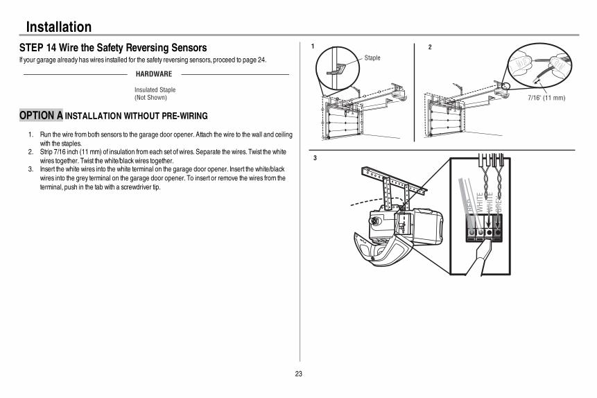
InstallationSTEP 14 Wire the Safety Reversing SensorsIf your garage already haswires installed for the safety reversing sensors, proceed to page 24.
HARDWARE
Insulated Staple
(Not Shown)
OPTION A INSTALLATION WITHOUT PRE-WIRING
1. Run the wire from both sensors to the garage door opener. Attach the wire to the wall and ceilingwith the staples.
2. Strip 7/16 inch (11 mm) of insulation from each set of wires. Separate the wires. Twist the whitewires together. Twist the white/black wires together.
3. Insert the white wires into the white terminal on the garage door opener. Insert the white/blackwires into the grey terminal on the garage door opener. To insert or remove the wires from theterminal, push in the tab with a screwdriver tip.
Staple
7/16" (11 mm)
WH
ITE
WH
ITE
GR
EY
RED
1 2
3

24
InstallationSTEP 14 Wire the Safety Reversing Sensors (continued)OPTION B PRE-WIRED INSTALLATION
1. Cut the end of the safety reversing sensor wire,making sure there is enough wire to reach thepre-installed wires from the wall.
2. Separate the safety reversing sensor wires and strip 7/16 inch (11 mm) of insulation from eachend. Choose two of the pre-installed wires and strip 7/16 inch (11 mm) of insulation from eachend.Make sure that you choose the same color pre-installed wires for each sensor.
3. Connect the pre-installed wires to the sensor wires with wire nutsmaking sure the colorscorrespond for each sensor. For example, the white wire would connect to the yellowwire andthe white/black wire would connect to the purple wire.
4. At the garage door opener, strip 7/16 inch (11 mm) of insulation from each end of the wirespreviously chosen for the safety reversing sensors. Twist the like-colored wires together.
5. Insert the wires connected to the white safety sensor wires to the white terminal on the garagedoor opener. Insert the wires that are connected to the white/black safety sensor wires to the greyterminal on the garage door opener.
Safety reversing sensor wires
Pre-installed wires
WhiteWhite/Black
Yellow (for example)
Purple (for example)
Not Provided
Pre-installed wires Safety reversing sensor wires
7/16" (11 mm)
Yellow
Purple
1
3
4
7/16" (11 mm)
2
WH
ITE
WH
ITE
RE
D
GR
EY
Purple(for example)
Yellow(for example)
To insert or remove the wires from the terminal, push in the tab with a screwdriver tip.
5

25
InstallationSTEP 15 Connect power
To prevent possible SERIOUS INJURY or DEATH from electrocution or fire:l Be sure power is NOT connected to the opener, and disconnect power to circuit BEFORE
removing cover to establish permanent wiring connection.l Garage door installation and wiring MUST be in compliance with ALL local electrical and building
codes.l NEVER use an extension cord, 2-wire adapter, or change plug in ANY way to make it fit outlet. Be
sure the opener is grounded.
To avoid installation difficulties, do not run the opener at this time.To reduce the risk of electric shock, your garage door opener has a grounding type plug with a thirdgrounding pin. This plug will only fit into a grounding type outlet. If the plug doesn’t fit into the outlet youhave, contact a qualified electrician to install the proper outlet.
THERE ARE TWO OPTIONS FORCONNECTING POWER:
OPTION A TYPICAL WIRING1. Plug in the garage door opener into a grounded outlet.2. DO NOT run garage door opener at this time.
OPTION B PERMANENT WIRINGIf permanent wiring is required by your local code, refer to the following procedure. Tomake apermanent connection through the 7/8 inch hole in the top of the motor unit (according to localcode):
1. Remove the motor unit cover screws and set the cover aside.2. Remove the attached 3-prong cord.3. Connect the black (line) wire to the screw on the brass terminal; the white (neutral) wire to the
screw on the silver terminal; and the ground wire to the green ground screw.The openermustbe grounded.
4. Reinstall the cover.
Ground Tab
Green
Ground
Screw
Ground
Wire
White Wire
Black Wire
Black Wire

26
InstallationSTEP 16 Aligning the safety reversing sensorsThe doorwill not close if the sensors have not been installed and aligned correctly.When the light beam is obstructed or misaligned while the door is closing, the door will reverse and thegarage door opener lights will flash ten times. If the door is already open, it will not close.
1. Check to make sure the LEDs in both sensors are glowing steadily. The LEDs in both sensors willglow steadily if they are aligned and wired correctly.
The sensors can be aligned by loosening the wing nuts, aligning the sensors, and tightening the wingnuts.
Green LEDAmber LED
If the receiving sensor is in direct sunlight, switch it with sending sensor so it is on the opposite side of the door.
(invisible light beam)
SENDING SENSOR RECEIVING SENSOR
IF THE AMBERLEDONTHE SENDING SENSOR IS NOTGLOWING:1. Make sure there is power to the garage door opener.2. Make sure the sensor wire is not shorted/broken.3. Make sure the sensor has been wired correctly: white wires to white terminal and white/black
wires to grey terminal.
RE
D
WH
ITE
WH
ITE
GR
EY
321
IF THE GREENLEDONTHE RECEIVING SENSOR IS NOTGLOWING:1. Make sure the sensor wire is not shorted/broken.2. Make sure the sensors are aligned.
1 2
STEP 17 Ensure the door control is wired correctlyIf the door control has been installed and wired correctly, a message will display on the Smart ControlPanel screen.

27
AdjustmentsIntroduction
Without a properly installed safety reversal system, persons (particularly small children) could beSERIOUSLY INJURED or KILLED by a closing garage door.l Incorrect adjustment of garage door travel limits will interfere with proper operation of safety
reversal system.l After ANY adjustments are made, the safety reversal systemMUST be tested. Door MUST reverse
on contact with 1-1/2" (3.8 cm) high object (or 2x4 laid flat) on floor.
To prevent damage to vehicles, be sure fully open door provides adequate clearance.
Your garage door opener is designed with electronic controls to make setup and adjustments easy. Theadjustments allow you to programwhere the door will stop in the open (UP) and close (DOWN) position.The electronic controls sense the amount of force required to open and close the door. The force isadjusted automatically when you program the travel.NOTE: If anything interferes with the door’s upward travel it will stop. If anything interferes with the door’sdownward travel, it will reverse.
UP (Open) DOWN (Close)
One-Piece Doors OnlyWhen setting the UP travel for a one-piece door ensure that the door does not slant backwards whenfully open (UP). If the door is slanted backwards this will cause unnecessary bucking and/or jerking whenthe door is opening or closing.
CORRECT
INCORRECT
Programming ButtonsThe programming buttons are located on the left side panel of the garage door opener and are used toprogram the travel.While programming, the UP and DOWNbuttons can be used to move the door asneeded.
UP Button
Adjustment Button
DOWN Button
PROGRAMMING BUTTONS
To watch a short instructional video on how to program the travel on yournew garage door opener use your smartphone to read the QRCode:

28
AdjustmentsSTEP 1 Program the Travel
Without a properly installed safety reversal system, persons (particularly small children) could beSERIOUSLY INJURED or KILLED by a closing garage door.l Incorrect adjustment of garage door travel limits will interfere with proper operation of safety
reversal system.l After ANY adjustments are made, the safety reversal systemMUST be tested. Door MUST reverse
on contact with 1-1/2" (3.8 cm) high object (or 2x4 laid flat) on floor.
While programming, the UP and DOWNbuttons can be used to move the door as needed.1. Press and hold the Adjustment Button until the UP Button begins to flash and/or a beep is heard.2. Press and hold the UP Button until the door is in the desired UP position.3. Once the door is in the desired UP position press and release the Adjustment Button. The
garage door opener lights will flash twice and the DOWNButton will begin to flash. IMPORTANTNOTE: For one-piece door installations refer to page 27.
4. Press and hold the DOWNbutton until the door is in the desired DOWNposition.5. Once the door is in the desired DOWNposition press and release the Adjustment Button. The
garage door opener lights will flash twice and the UP Button will begin to flash.6. Press and release the UP Button.When the door travels to the programmed UP position, the
DOWNButton will begin to flash.7. Press and release the DOWNButton. The door will travel to the programmed DOWNposition.
Programming is complete.* If the garage door opener lights are flashing 5 times during the steps for Program the Travel, theprogramming has timed out. If the garage door opener lights are flashing 10 times during the steps forProgram the Travel, the safety reversing sensors are misaligned or obstructed (refer to page 26).Whenthe sensors are aligned and unobstructed, cycle the door through a complete up and down cycle usingthe remote control or the UP and DOWNbuttons. Programming is complete. If you are unable to operatethe door up and down, repeat the steps for Programming the Travel.
UP Button
Adjustment Button
DOWN Button
PROGRAMMING BUTTONS
1 2 3
4 5
6 7
29
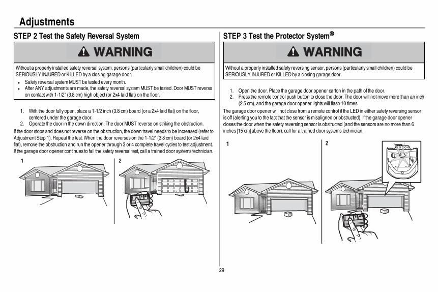
AdjustmentsSTEP 2 Test the Safety Reversal System
Without a properly installed safety reversal system, persons (particularly small children) could beSERIOUSLY INJURED or KILLED by a closing garage door.l Safety reversal systemMUST be tested everymonth.l After ANY adjustments are made, the safety reversal systemMUST be tested. Door MUST reverse
on contact with 1-1/2" (3.8 cm) high object (or 2x4 laid flat) on the floor.
1. With the door fully open, place a 1-1/2 inch (3.8 cm) board (or a 2x4 laid flat) on the floor,centered under the garage door.
2. Operate the door in the down direction. The door MUST reverse on striking the obstruction.If the door stops and does not reverse on the obstruction, the down travel needs to be increased (refer toAdjustment Step 1). Repeat the test.When the door reverses on the 1-1/2" (3.8 cm) board (or 2x4 laidflat), remove the obstruction and run the opener through 3 or 4 complete travel cycles to test adjustment.If the garage door opener continues to fail the safety reversal test, call a trained door systems technician.
1 2
STEP 3 Test the Protector System®
Without a properly installed safety reversing sensor, persons (particularly small children) could beSERIOUSLY INJURED or KILLED by a closing garage door.
1. Open the door. Place the garage door opener carton in the path of the door.2. Press the remote control push button to close the door. The door will notmove more than an inch
(2.5 cm), and the garage door opener lights will flash 10 times.The garage door opener will not close from a remote control if the LED in either safety reversing sensoris off (alerting you to the fact that the sensor ismisaligned or obstructed). If the garage door openercloses the door when the safety reversing sensor is obstructed (and the sensors are no more than 6inches [15 cm] above the floor), call for a trained door systems technician.
1 2

30
Battery BackupSTEP 1 Install the Battery
To reduce the risk of FIRE or INJURY to persons:l Disconnect ALL electric and battery power BEFORE performing ANY service or maintenance.l Use ONLY Chamberlain part # 41A6357-1 for replacement battery.l DO NOT dispose of battery in fire. Batterymay explode. Checkwith local codes for disposal
instructions.
ALWAYS wear protective gloves and eye protection when changing the battery or working around thebattery compartment.
The battery backup allows access in and out of your garage, even when the power is out. The batterydoes not have to be fully charged to operate the garage door opener.When the garage door opener isoperating on battery power, it will run slower and the battery status LEDwill glow solid orange, a beepwill sound approximately every 2 seconds. The following features are unavailable when operating onbattery power:
l Garage Door Opener Lightsl Unattended close devices and features (e.g.MyQ®Smartphone Control and Timer-to-Close)
Battery Status LED
1. Unplug the garage door opener.2. Open the light lens on the right side panel of the garage door opener. Use a Phillips head
screwdriver to remove the battery cover on the garage door opener.3. Partially insert the battery into the battery compartment with the terminals facing out.4. Connect red (+) and black (-) wires from the garage door opener to the corresponding terminals
on the battery.
5. Replace the battery cover and plug in the garage door opener.6. Wait for the green Battery Status LED to start flashing before proceeding to test the battery.
STEP 2 Test the Battery1. Unplug the garage door opener. The battery status LEDwill glow solid orange indicating opener
is operating on battery power or will flash indicating low battery power.2. Open and close the door using the remote control or door control.3. Plug in the garage door opener. Verify the battery status LED is flashing green, indicating the
battery is charging.
1 2 3
Charge the BatteryThe battery chargeswhile the garage door opener is plugged into an electrical outlet. The batteryrequires 24 hours to fully charge. A fully charged battery supplies 12Vdc to the garage door opener forone to two days of normal operation during an electrical power outage. After the electrical power hasbeen restored, the battery will recharge within 24 hours. The battery will last approximately 1 to 2 yearswith normal usage. To obtain maximum battery life and prevent damage, disconnect the battery when thegarage door opener is unplugged for an extended period of time, such as a summer or winter home.

31
MyQ® Smartphone ControlGet Connected…and control your garage door opener with the MyQ®App.Youwill need:
l A smartphone or tabletl Broadband Internet connectionl A strong Wi-Fi signal in the garage, see page 2l Password for your home networkl MyQ® serial number located on the garage door opener
1. ACTIVATE "WI-FI LEARN" MODEPress and release the yellow LEARN button on the garage door opener 3 times. The garage dooropener will beep once and a blue light will flash. You have 20 minutes to complete the connectionprocess.
“beep”
Blue LED
2. CONNECT TO THE MyQ® Wi-Fi NETWORKOn your mobile device, go to Settings >Wi-Fi, and select the network with the "MyQ-" prefix.
3. CONNECT THE GARAGE DOOR OPENER TO YOUR HOME WI-FI NETWORKLaunch the web browser (such as Safari or Chrome) on your mobile device and go to"setup.myqdevice.com". Follow the on-screen prompts to add the garage door opener to your homeWi-Fi network.
ATT 100%9:25 PM
http://setup.myqdevice.com
Welcome. This step-by-step guide will
help you connect your Wi-Fi Garage Door
Opener to the internet through your
home’s Wi-Fi network.
Press Start to begin the process by
scanning for available networks.
Tap EXIT to reconnect your mobile device to your
home’s Wi-Fi network.
©2014 The Chamberlain Group, Inc.
About
Exit
Start
4. SETUP YOUR MyQ® ACCOUNTDownload the MyQ® app from the App StoreSM or Google Play™ store. Sign up for your MyQ® accountand add the MyQ® serial number to your account.
Google Play
App Store
or
Congratulations you've successfully completed the setup. Enjoy MyQ®Smartphone Control!
In addition to controlling your garage door opener you can control your house lighting with additionalMyQ® accessories, see page 40.
NOTES:The MyQ®Smartphone Control WILL NOTwork if the garage door opener is operating on battery power.To erase the Wi-Fi settings, see page 36.
To learn more go to wifihelp.chamberlain.com.

32
IMPORTANT SAFETY INSTRUCTIONS
To reduce the risk of SEVERE INJURY or DEATH:1. READANDFOLLOWALL WARNINGS AND INSTRUCTIONS.2. ALWAYS keep remote controls out of reach of children. NEVER permit children to operate
or play with garage door control push buttons or remote controls.3. ONLY activate garage door when it can be seen clearly, it is properly adjusted, and there
are no obstructions to door travel.4. ALWAYS keep garage door in sight and away from people and objects until completely
closed. NO ONE SHOULDCROSS THE PATHOFTHE MOVING DOOR.5. NO ONE SHOULDGO UNDERA STOPPED, PARTIALLY OPENEDDOOR.6. If possible, use emergency release handle to disengage trolleyONLY when garage door is
CLOSED.Use caution when using this release with the door open.Weak or broken springsor unbalanced door could result in an open door falling rapidly and/or unexpectedly andincreasing the risk of SEVERE INJURY or DEATH.
7. NEVER use emergency release handle unless garage doorway is clear of persons andobstructions.
8. NEVER use handle to pull garage door open or closed. If rope knot becomes untied, youcould fall.
9. After ANY adjustments are made, the safety reversal systemMUST be tested.10. Safety reversal systemMUST be tested everymonth. Garage door MUST reverse on contact with
1-1/2" (3.8 cm) high object (or a 2x4 laid flat) on the floor. Failure to adjust the garage dooropener properly increases the risk of SEVERE INJURY or DEATH.
11. ALWAYS KEEP GARAGE DOORPROPERLY BALANCED (see page 1). An improperlybalanced door mayNOT reverse when required and could result in SEVERE INJURY orDEATH.
12. ALL repairs to cables, spring assemblies and other hardware, ALL of which are underEXTREME tension,MUST be made by a trained door systems technician.
13. ALWAYS disconnect electric and battery power to garage door opener BEFORE making ANYrepairs or removing covers.
14. This operator system is equipped with an unattended operation feature. The door could moveunexpectedly. NO ONE SHOULDCROSS THE PATHOFTHE MOVING DOOR.
15. DO NOT install on a one-piece door if using devices or features providing unattended close.Unattended devices and features are to be used ONLY with sectional doors.
16. SAVE THESE INSTRUCTIONS.
Operation

33
OperationUsing your Garage Door Opener
l The garage door opener can be activated with a wall-mounted door control, remote control,wireless keyless entry,MyQ®Smartphone Control app or MyQ®Garage Door Monitor.When thedoor is closed and the garage door opener is activated the door will open. If the door senses anobstruction or is interrupted while opening the door will stop.When the door is in any positionother than closed and the garage door opener is activated the door will close. If the garage dooropener senses an obstruction while closing, the door will reverse. If the obstruction interrupts thesensor beam the garage door opener lights will blink 10 times. If the door is fully open, and thesafety reversing sensors are not installed, or are misaligned, the door will not close from a remotecontrol, TTC, or the MyQ®Smartphone Control app. However, you can close the door by holdingthe button on the door control or the ENTER button on the keyless entry until the door is fullyclosed.
l The garage door opener light bulbs will turn on when the opener is initially plugged in; power isrestored after interruption, or when the garage door opener is activated. The lights will turn offautomatically after 4-1/2 minutes. The lights will turn on when someone enters through the opengarage door and the safety reversing sensor infrared beam is obstructed, see page 33. Use anincandescent A19 light bulb (100 watt maximum) or for maximum energy efficiency a 26W (100Wequivalent) compact fluorescent light (CFL) bulb.NOTE: Do not use halogen, short neck, orspecialty light bulbs as these may overheat the end panel or light socket. Do not use LED bulbsas theymay reduce the range or performance of your remote controls.
To Open the Door Manually
To prevent possible SERIOUS INJURY or DEATH from a falling garage door:l If possible, use emergency release handle to disengage trolleyONLY when garage door is
CLOSED.Weak or broken springs or unbalanced door could result in an open door fallingrapidly and/or unexpectedly.
l NEVER use emergency release handle unless garage doorway is clear of persons andobstructions.
l NEVER use handle to pull door open or closed. If rope knot becomes untied, you could fall.
DISCONNECT THE TROLLEY1. The door should be fully closed if possible.2. Pull down on the emergency release handle so the trolley release arm snaps to the vertical
position. The door can now be raised and lowered as often as necessary.
TO RECONNECT THE TROLLEY1. Pull the emergency release handle toward the garage door opener so the trolley release arm
snaps to the horizontal position. The trolley will reconnect on the next UP or DOWNoperation,either manually or by using the door control or remote control.

34
OperationDoor ControlSYNCHRONIZE THE DOORCONTROL: To synchronize the door control to the garage door opener,press the push bar until the garage door opener activates (it may take up to 3 presses). Test the doorcontrol by pressing the push bar; each press of the push bar will activate the garage door opener.
Push Bar
LIGHT Button
Motion Sensor
Navigation Buttons
Screen
PUSHBAR: Press the push bar to open or close the door.
LIGHTBUTTON: Press the LIGHT button to turn the garage door opener lights on or off.When the lightsare turned on they will stay on until the LIGHT button is pressed again, or until the garage door opener isactivated. Once the garage door opener is activated the lights will turn off after the specified period oftime (the factory default is 4-1/2 minutes). The LIGHT button will not control the lights when the door is inmotion. The Light Feature will turn on the light on the garage door opener when someone entersthrough the open garage door and the safety reversing sensor infrared beam is obstructed.
MOTIONSENSOR: The motion sensor automatically turns on the garage door opener lights whenmotion is detected. The lights come on for the set period of time, and then shut off. If using the garagedoor opener light as a work light disable the motion sensor, otherwise the lightsmay turn off automaticallyif you are beyond the range of the motion sensor.
NAVIGATIONANDSCREEN: The screen displays the time, temperature, and current battery charge (ifapplicable) until the menu button is pressed, and then it will display the menu options. If there is aproblemwith the garage doors opener the screen will display an error code (diagnostic code, see page38). The features on the door control can be programmed through a series ofmenus on the screen. Usethe navigation buttons to scroll through the menus and make selections.
MENU OPTIONS
CLOCKSETUP: Set the time; choose 12 or 24 hour clock and show/hide clock.TEMPERATURE: Display the temperature in Fahrenheit or Celsius and show/hide the temperature.LANGUAGE: Select English, Spanish or French.CONTRASTADJUST: Adjust the screen contrast.LIGHTSETTINGS:To change the amount of time the lights stay on:
1. Select LIGHTSETTINGS from the menu.2. Select LIGHT TIME.3. Select the time interval.
To turn the Light Feature on or off (Factory default is On):1. Select LIGHTSETTINGS from the menu.2. Select AUTOMATIC LIGHTS.3. Select ENTRY SENSOR.
To turn the motion sensor on or off:1. Select LIGHTSETTINGS from the menu.2. Select AUTOMATIC LIGHTS.3. SelectMOTIONSENSOR.
LOCK: Prevents the garage door opener from being activated by remote controls while still allowingactivation from the door control and keyless entry.To turn the LOCK feature ON or OFF:
1. Select LOCK from the menu.When the LOCK feature is on, a message displays on the screen.

35
OperationMENU OPTIONS (CONTINUED)TIMER-TO-CLOSE (TTC) (Factory default is set to off): The Timer-to-Close feature automaticallycloses the door after a specified time period and can be adjusted using the door control. DO NOT enableTTC if operating a one-piece door. TTC is to be used ONLY with sectional doors. The garage dooropener will beep and the lights will flash before closing the door. The TTC feature will deactivate if thegarage door encounters an obstruction twice; or the safety reversing sensors are incorrectly installed.The garage door will reverse open and WILL NOT close until the obstructions are clear or the safetyreversing sensors are correctly installed.When the obstruction has been cleared or the safety reversingsensors have been aligned, the door will close when the garage door opener is activated. TTCWILLNOTwork if the garage door opener is operating by battery power or if the safety reversing sensors aremisaligned. This feature is NOT intended to be the primarymethod of closing the door. A keyless entryshould be installed in the event of an accidental lock out when using this feature.To turn TTC on or off or to set the TTC time interval:
1. Select TTC from the menu.2. Select a time interval of 1, 5, 10 minutes or a custom setting up to 99 minutes. Once the TTC has
been set and the door is open, a message will display on the screen with the selected timeinterval.
To temporarily suspend the TTC feature select HOLD. Select REL to resume normal TTC operation.PROGRAM: Any compatible remote control, wireless keyless entry, or MyQ® devices can beprogrammed to the garage door using the PROGRAMoption from the menu.
Remote Control and Keyless EntryYour remote control has been programmed at the factory to operate with your garage door opener,randomly accessing over 100 billion new codes with each use.Your garage door opener can beprogrammed with up to 8 remote controls, 1 keyless entry, 2 Security+ 2.0™ door controls and 6 MyQ®
accessories. Older Chamberlain remote controls are NOT compatible, see page 40 for compatibleaccessories.Programming can be done through the door control or the learn button on the garage door opener. Toprogram additional accessories refer to the instructions provided with the accessory or visitwww.chamberlain.com. If your vehicle is equipped with HomeLink®, a Compatibility Bridge™ (notincluded) may be necessary for certain vehicles. Visit bridge.chamberlain.com to find out if a Bridge isneeded.TO ADD, REPROGRAM, OR CHANGE A REMOTE CONTROL/KEYLESS ENTRY PINUSING THE DOOR CONTROL
1. Press the navigation button below "MENU" to view the Featuresmenu.2. Use the navigation buttons to scroll to "PROGRAM".3. Select "REMOTE" or "KEYPAD" to program from the programmenu.4. Remote Control: Press the button on the remote control that you wish to operate your garage
door.Keyless Entry: Enter a 4-digit personal identification number (PIN) of your choice on the keylessentry keypad. Then press the ENTER button.
The garage door opener lights will flash (or two clicks will be heard) when the code has beenprogrammed. Repeat the steps for programming additional remote controls or keyless entry devices. Ifprogramming is unsuccessful, repeat the steps using the learn button on the garage door opener.
1 2 3
OR
PIN
? ? ? ?
4
Press to continue. Press to continue.

36
OperationTo Erase the MemoryERASE ALL REMOTE CONTROLS AND KEYLESS ENTRIES
1. Press and hold the LEARN button on garage door opener until the learn LED goes out(approximately 6 seconds). All remote control and keyless entry codes are now erased.Reprogram any accessory you wish to use.
ERASE ALL REMOTE CONTROLS, KEYLESS ENTRIES AND MyQ® DEVICES FROMGARAGE DOOR OPENER
1. Press and hold the LEARN button on garage door opener until the learn LED goes out(approximately 6 seconds).
2. Immediately press and hold the LEARN button again until the learn LED goes out. All codes arenow erased. Reprogram any accessory you wish to use.
ERASE THE CONNECTION FROM GARAGE DOOR OPENER TO HOME Wi-FiNETWORK
1. Press and hold the black adjustment button on the garage door opener until 3 beeps are heard(Approximately 6 seconds).
ERASE A MyQ® ACCOUNT1. Go to www.mychamberlain.com to access your MyQ® account.2. Click on the "Account" tab.3. Click "Edit User".4. Click "Delete this account".5. Click "Delete".
Go to wifihelp.chamberlain.com for more details.

37
MaintenanceMaintenance ScheduleEVERY MONTHl Manually operate door. If it is unbalanced or binding, call a trained door systems technician.l Check to be sure door opens and closes fully. Adjust if necessary, see page 27.l Test the safety reversal system. Adjust if necessary, see page 29.EVERY YEARl Oil door rollers, bearings and hinges. The garage door opener does not require additional
lubrication. Do not grease the door tracks.l Test the battery backup and consider replacing the battery to ensure the garage door opener will
operate during an electrical power outage, see page 30 to test the battery backup.
The Remote Control Battery
To prevent possible SERIOUS INJURY or DEATH:l NEVER allow small children near batteries.l If battery is swallowed, immediately notify doctor.To reduce risk of fire, explosion or chemical burn:l Replace ONLY with 3V CR2032 coin batteries.l DO NOT recharge, disassemble, heat above 212°F (100°C) or incinerate.
The 3V CR2032 lithium battery should produce power forup to 3 years. If the battery is low, the remote control’s LEDwill not flash when the button is pressed.To replace battery, pry open the case first in the middle (1),then at each side (2 and 3) with the visor clip. Replace thebatteries with only 3V CR2032 coin cell batteries. Insertbattery positive side up. Dispose of old batteries properly. 1
2
3
NOTICE: To complywith FCC and/or IndustryCanada (IC) rules, adjustment ormodificationsof this transceiverare prohibited. THEREARENOUSERSERVICEABLEPARTS.Thisdevice complieswith Part 15 of the FCC rulesand ICRSS-210. Operation issubject to the following two conditions: (1) thisdevicemaynot cause harmfulinterference, and (2) thisdevice must accept any interference received, including interference thatmaycauseundesired operation.Thisdevice must be installed in a waywhere a minimum8"(20cm)distance ismaintained between users/bystandersand device.
AVIS: Lesrèglesde la FCC et/ou d’Industrie Canada (IC) interdisent tout ajustement ou toute modification de ce récepteur. IL N’EXISTEAUCUNEPIÈCESUSCEPTIBLED’ÊTREENTRETENUEPAR L’UTILISATEUR.Cet appareilest conforme auxdispositionsde la partie 15 du règlement de la FCC et de l'norme ICRSS-210. Son utilisation est assujettieauxdeuxconditoinssuivantes: (1)ce dispositif ne peut causerdesinterférencesnuisibles, et (2)ce dispositif doit accepter touteinterférence recue, ycomprisune interférence pouvant causerun fonctionnement non souhaité.Cet appareildoit être installé de manière à laisserune distance d’au moins20 cm(8 po)entre celui-ciet l’utilisateurou toute personne.
38
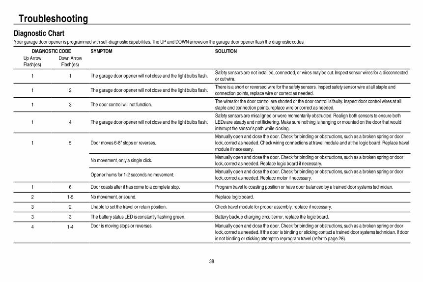
Diagnostic ChartYour garage door opener is programmed with self-diagnostic capabilities. The UP and DOWNarrows on the garage door opener flash the diagnostic codes.
DIAGNOSTICCODE SYMPTOM SOLUTIONUp ArrowFlash(es)
Down ArrowFlash(es)
1 1 The garage door opener will not close and the light bulbs flash.Safety sensors are not installed, connected, or wiresmay be cut. Inspect sensor wires for a disconnectedor cut wire.
1 2 The garage door opener will not close and the light bulbs flash.There is a short or reversed wire for the safety sensors. Inspect safety sensor wire at all staple andconnection points, replace wire or correct as needed.
1 3 The door control will not function.The wires for the door control are shorted or the door control is faulty. Inspect door control wires at allstaple and connection points, replace wire or correct as needed.
1 4 The garage door opener will not close and the light bulbs flash.Safety sensors are misaligned or were momentarily obstructed. Realign both sensors to ensure bothLEDs are steady and not flickering.Make sure nothing is hanging or mounted on the door that wouldinterrupt the sensor’s path while closing.
1 5 Door moves 6-8" stops or reverses.Manually open and close the door. Check for binding or obstructions, such as a broken spring or doorlock, correct as needed. Checkwiring connections at travel module and at the logic board. Replace travelmodule if necessary.
No movement, only a single click.Manually open and close the door. Check for binding or obstructions, such as a broken spring or doorlock, correct as needed. Replace logic board if necessary.
Opener hums for 1-2 seconds no movement.Manually open and close the door. Check for binding or obstructions, such as a broken spring or doorlock, correct as needed. Replace motor if necessary.
1 6 Door coasts after it has come to a complete stop. Program travel to coasting position or have door balanced by a trained door systems technician.
2 1-5 No movement, or sound. Replace logic board.
3 2 Unable to set the travel or retain position. Check travel module for proper assembly, replace if necessary.
3 3 The battery status LED is constantly flashing green. Battery backup charging circuit error, replace the logic board.
4 1-4 Door ismoving stops or reverses. Manually open and close the door. Check for binding or obstructions, such as a broken spring or doorlock, correct as needed. If the door is binding or sticking contact a trained door systems technician. If dooris not binding or sticking attempt to reprogram travel (refer to page 28).
Troubleshooting
39
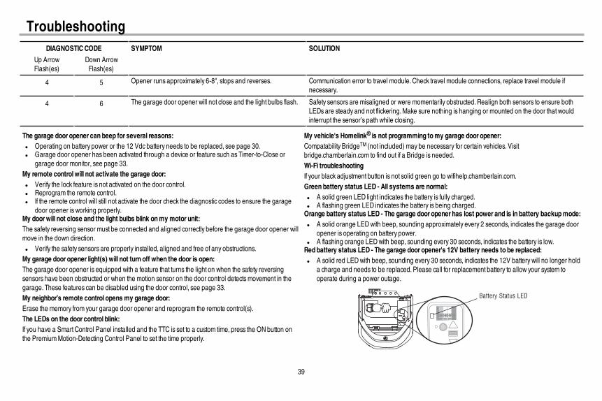
DIAGNOSTICCODE SYMPTOM SOLUTION
Up ArrowFlash(es)
Down ArrowFlash(es)
4 5 Opener runs approximately 6-8", stops and reverses. Communication error to travel module. Check travel module connections, replace travel module ifnecessary.
4 6 The garage door opener will not close and the light bulbs flash. Safety sensors are misaligned or were momentarily obstructed. Realign both sensors to ensure bothLEDs are steady and not flickering.Make sure nothing is hanging or mounted on the door that wouldinterrupt the sensor’s path while closing.
The garage door opener can beep for several reasons:l Operating on battery power or the 12 Vdc battery needs to be replaced, see page 30.l Garage door opener has been activated through a device or feature such as Timer-to-Close or
garage door monitor, see page 33.My remote control will not activate the garage door:l Verify the lock feature is not activated on the door control.l Reprogram the remote control.l If the remote control will still not activate the door check the diagnostic codes to ensure the garage
door opener is working properly.My doorwill not close and the light bulbs blink onmy motor unit:The safety reversing sensor must be connected and aligned correctly before the garage door opener willmove in the down direction.l Verify the safety sensors are properly installed, aligned and free of any obstructions.My garage door opener light(s) will not turn off when the door is open:The garage door opener is equipped with a feature that turns the light on when the safety reversingsensors have been obstructed or when the motion sensor on the door control detectsmovement in thegarage. These features can be disabled using the door control, see page 33.My neighbor’s remote control opens my garage door:Erase the memory from your garage door opener and reprogram the remote control(s).The LEDs on the door control blink:If you have a Smart Control Panel installed and the TTC is set to a custom time, press the ON button onthe PremiumMotion-Detecting Control Panel to set the time properly.
My vehicle's Homelink® is not programming tomy garage door opener:Compatability BridgeTM (not included) may be necessary for certain vehicles. Visitbridge.chamberlain.com to find out if a Bridge is needed.Wi-Fi troubleshootingIf your black adjustment button is not solid green go to wifihelp.chamberlain.com.Green battery status LED - All systems are normal:l A solid green LED light indicates the battery is fully charged.l A flashing green LED indicates the battery is being charged.Orange battery status LED - The garage door opener has lost power and is in battery backupmode:l A solid orange LEDwith beep, sounding approximately every 2 seconds, indicates the garage door
opener is operating on battery power.l A flashing orange LEDwith beep, sounding every 30 seconds, indicates the battery is low.Red battery status LED - The garage door opener's 12V battery needs to be replaced:l A solid red LEDwith beep, sounding every 30 seconds, indicates the 12V battery will no longer hold
a charge and needs to be replaced. Please call for replacement battery to allow your system tooperate during a power outage.
Battery Status LED
Troubleshooting

40
Accessories
CLLP1
953EV
Laser Parking Assistant:Park in the right spot every time! A laser beam is activated by yourgarage door opener and projected on to the dashboard of your vehicle to guide perfect parking.
Remote Control:Works with ALL Chamberlain openers from 1993-present. MyQ® compatible. Includes visor clip.
AGDMEV Garage Door Monitor:Monitor open/closed status for up to 4 MyQ® compatible garage door openers or gate operators and close them from anywhere in the home.
956EV Keychain Remote Control:Works with ALL Chamberlain openers from 1993-present. MyQ® compatible. With key ring.
940EV Wireless Keypad:For use outside of the home to enable access to the garage using a 4-digit PIN. Works with ALL Chamberlain openers from 1993-present. MyQ® compatible.
PILCEV MyQ® Remote Lamp Control:Monitor and control this plug in lamp switch with the MyQ® Smartphone App.
You can program up to 10 MyQ® accessories to your MyQ® account.
WSLCEV MyQ® Interior/Exterior Light SwitchMonitor and control this wall light switch with the MyQ® Smartphone App.
Extension Brackets:(Optional) For safety reversing sensor installation onto the wall or fl oor.
CLOSED
OPEN
041A5281-1
8810CB 10 Foot (3 m) Rail Extension:To allow a 10 foot (3 m) door to open fully.
8 Foot (2.4 m) Rail Extension:To allow an 8 foot (2.4 m) door to open fully.
8808CB 41A6357-1 Standby Power System Battery:Provides backup power to the garage door opener.
CIGBU
MyQ® Accessories
MyQ® Internet Gateway:Offers longer range wireless signal than standard Wi-Fi. Plugs into your home router as an optional way to provide MyQ® Smartphone Control for your garage door opener and MyQ® light controls.

41
Warranty CHAMBERLAIN® LIMITED WARRANTYThe Chamberlain Group, Inc.® (“Seller”) warrants to the fi rst retail purchaser of this product, for the residence in which this product is originally installed, that it is free from defects in materials and/or workmanship for a specifi c period of time as defi ned below (the “Warranty Period”). The warranty period commences from the date of purchase.
WARRANTY PERIODParts Motor Accessories Belt Battery Backup5 Years Lifetime 1 year Lifetime 1 year
The proper operation of this product is dependent on your compliance with the instructions regarding installation, operation, and maintenance and testing. Failure to comply strictly with those instructions will void this limited warranty in its entirety. If, during the limited warranty period, this product appears to contain a defect covered by this limited warranty, call 1-800- 528-9131, toll free, before dismantling this product. You will be advised of disassembly and shipping instructions when you call. Then send the product or component, pre-paid and insured, as directed to our service center for warranty repair. Please include a brief description of the problem and a dated proof- of-purchase receipt with any product returned for warranty repair. Products returned to Seller for warranty repair, which upon receipt by Seller are confi rmed to be defective and covered by this limited warranty, will be repaired or replaced (at Seller’s sole option) at no cost to you and returned pre-paid. Defective parts will be repaired or replaced with new or factory rebuilt parts at Seller’s sole option. [You are responsible for any costs incurred in removing and/or reinstalling the product or any component .]
ALL IMPLIED WARRANTIES FOR THE PRODUCT, INCLUDING BUT NOT LIMITED TO ANY IMPLIED WARRANTIES OF MERCHANTABILITY AND FITNESS FOR A PARTICULAR PURPOSE, ARE LIMITED IN DURATION TO THE APPLICABLE LIMITED WARRANTY PERIOD SET FORTH ABOVE FOR THE RELATED COMPONENT(S), AND NO IMPLIED WARRANTIES WILL EXIST OR APPLY AFTER SUCH PERIOD. Some States and Provinces do not allow limitations on how long an implied warranty lasts, so the above limitation may not apply to you. THIS LIMITED WARRANTY DOES NOT COVER NON-DEFECT DAMAGE, DAMAGE CAUSED BY IMPROPER INSTALLATION, OPERATION OR CARE (INCLUDING, BUT NOT LIMITED TO ABUSE, MISUSE, FAILURE TO PROVIDE REASONABLE AND NECESSARY MAINTENANCE, UNAUTHORIZED REPAIRS OR ANY ALTERATIONS TO THIS PRODUCT), LABOR CHARGES FOR REINSTALLING A REPAIRED OR REPLACED UNIT, REPLACEMENT OF CONSUMABLE ITEMS (E.G., BATTERIES IN REMOTE CONTROL TRANSMITTERS AND LIGHT BULBS), OR UNITS INSTALLED FOR NON-RESIDENTIAL USE. THIS LIMITED WARRANTY DOES NOT COVER ANY PROBLEMS WITH, OR RELATING TO, THE GARAGE DOOR OR GARAGE DOOR HARDWARE, INCLUDING BUT NOT LIMITED TO THE DOOR SPRINGS, DOOR ROLLERS, DOOR ALIGNMENT OR HINGES. THIS LIMITED WARRANTY ALSO DOES NOT COVER ANY PROBLEMS CAUSED BY INTERFERENCE. UNDER NO CIRCUMSTANCES SHALL SELLER BE LIABLE FOR CONSEQUENTIAL, INCIDENTAL OR SPECIAL DAMAGES ARISING IN CONNECTION WITH USE, OR INABILITY TO USE, THIS PRODUCT. IN NO EVENT SHALL SELLER’S LIABILITY FOR BREACH OF WARRANTY, BREACH OF CONTRACT, NEGLIGENCE OR STRICT LIABILITY EXCEED THE COST OF THE PRODUCT COVERED HEREBY. NO PERSON IS AUTHORIZED TO ASSUME FOR US ANY OTHER LIABILITY IN CONNECTION WITH THE SALE OF THIS PRODUCT.
Some states and provinces do not allow the exclusion or limitation of consequential, incidental or special damages, so the above limitation or exclusion may not apply to you. This limited warranty gives you specifi c legal rights, and you may also have other rights, which vary from state to state and province to province.
Contact InformationFor installation and service information, please visit:
www.chamberlain.com/parts-and-support
If you are ordering a repair part please have the following information: part number, part name, and model number.
Address repair parts orders to:The Chamberlain Group, Inc.6050 S. Country Club Road
Tucson, AZ 85706
Register your new garage door opener at www.prodregister.com/chamberlain
STOP!This garage door opener WILL NOT work until the
safety reversing sensors are properly installed and aligned.

42
Repair PartsRail Assembly Parts
Accessories
Installation Parts
1
3
2
4
6
5
1
2
NOTICE
1
3
4
2
5
6
7
8
9
10
11
Description Part Number1 Belt 41A5250
2 Pulley 144C54
3 Master Link 4A1008
4 Rail 41A5665
5 Trolley Assembly 41C5141-2
6 “U” Bracket 12D598-1
Not Shown
Wear Pads 183A163
Hardware Bag 041A7920-2
Description Part Number
1 Smart Control Panel® 41A7305-1
2 Remote Control 953ESTD
Description Part Number1 Curved Door Arm 178B35
2 Door Bracket with Clevis Pin and Fastener
41A5047-1
3 Emergency Release Rope and Handle
41A2828
4 Header Bracket with Clevis Pin and Fastener
41A5047-2
5 Remote Control Visor Clip
29B137
6 Safety Sensor Bracket 041A5266-3
7 Safety Sensor Kit Receiving and sending sensors with wire
41A5034
8 Straight Door Arm 178B34
9 White and Red/White Wire 41B4494-1
10 3V CR2032 Lithium Battery
10A20
11 Hanging Brackets 12B776
Not Shown
Owner’s Manual 114A4763

1
7
5
3
4
3
9
6
82
410
Repair Parts Description Part Number1 Sprocket and Sprocket Cover with Screws 041C1751
2 End Panel with light socket 041D7639-1
3 Light LensWD1000WFHD950WFLW9000WF
041D7570041D7572041D7571
4 Light Socket 041C0279
5 Transformer 041D0277-1
6 Cover 041D0614-23
7 Motor with Travel Module 041D1739-1
8 End Panel for Receiver Logic Board with light socket 041D8214
9 Receiver Logic Board 050DCTWF
10 Travel Module 041A7114-7
Garage Door Opener Parts
© 2014, The Chamberlain Group, Inc. All Rights Reserved Wi-Fi® is a registered trademark of Wi-Fi Alliance App Store is a service mark of Apple Inc.114A4763E Google Play is a trademark of Google Inc.