Embed Size (px)
Citation preview

Global Fire Equipment // globalfire.pt ma_chmcomm_01_010000_en_190516
CHAMELEON NETWORK
INSTALLATION & COMMISSIONING MANUAL
OVERVIEW 3
CHAMELEON NETWORK KEY FEATURES 3 MULTI MASTER 3 NETWORKABLE PANELS 3 SYSTEM LIMITATIONS 4 TERMS and DEFINITIONS 4 IDENTIFYING COMPONENTS and COMMUNICATIONS 5 COMMUNICATION INTERFACES 7
INSTALLATION 8 INTRODUCTION 8
Mains Power connection 8 Control Panels and Repeaters Location 8
CHAMELEON NETWORK TOPOLOGY 9 Closed Loop Network example 9 Open Loop Network example 10 Mesh Network example 10 Extended display example (on non networked systems) 11
PANEL CONNECTIONS 12 RS422 connections example 13 FIBRE-OPTIC connections example 13 CHAMELEON REPEATER with double RS422 interface 15 Single TCP/IP Peer to Peer Connection 16
RECOMMENDED CABLES 16
COMMISSIONING 17 INTRODUCTION 17 GETTING THE PANEL/REPEATER RUNNING 17 NETWORK FUNCTIONS 18
Complete list of functions 18 Specific Network Related Functions 19
STEP BY STEP NETWORK COMMISSIONING 22 Open network LOOP 22 Power Up in Installation Mode 22 Panel Lamp Check 22
1

Global Fire Equipment // globalfire.pt ma_chmcomm_01_010000_en_190516
Check Panel Address 22 Check Panel Version 22 Check All Communication Channels (CHx) 22 Check Known Panels 23 Debug Network messages 23 Restart Network Panels 23 Close network LOOP 23 Upload and Broadcast Configuration to the network 23 Clear NVRAM 23 Wait 2 minutes for network recognition 23 Change system to Active Mode 23 Verify remote devices on the installation 24
TROUBLESHOOTING 24 “COMMUNICATION FAILURE” 24
RX connection break on Panel 2 (disconnect RX1 or RX2) 24 TX1 connection break on Panel 2 25 TX2 connection break on Panel 2 25
“PANEL CONFIGURATION MISMATCH” 26 One Panel in ACTIVE MODE and all other in INSTALLATION MODE 26 Upload a configuration without broadcast 27 Selective Disablements different between panels 28
8-5-2 Known Panels - Debug on communications 29 Commissioning phase with “open loop” topology, with Panels on Installation Mode. 29 Commissioning phase with “closed loop” topology, with Panels on Installation Mode. 29
2

Global Fire Equipment // globalfire.pt ma_chmcomm_01_010000_en_190516
OVERVIEW This document covers the installation and commissioning of Chameleon Networked Panels. It is intended for use by a competent, qualified, fire alarm installation engineer with basic knowledge of networked systems. All Chameleon Network Panels should be tailored to the building/site requirements. The complete system should be designed to meet all applicable regulations. The installation must then be performed in accordance with the system design. This manual not only clarifies the components and connections during installation, but will also assist in commissioning and maintenance. CHAMELEON NETWORK KEY FEATURES ● Multipath “mesh” topology VS double ring topology
● Network packages are buffered and retransmitted in each node (signals are electrically rebuilt)
● “Multi master” approach (independent panels with global system awareness)
● Panel action is event driven
● Each Panel has an independent “SYSTEM EVENT LOG” (rolling 10000 entries)
● Customer configuration can be broadcasted to all panels over the network
● High Immunity in high latency network connections
● Configuration mismatch detection between system panels
● Hour sync between panels
● Maximum of 32 panels
● System Repeaters (CHAMELEON REP) via RS422, Fibre-Optics, Serial and TCP/IP
● Future Online Mode support with Chameleon Software (in development, currently not available).
MULTI MASTER One of the major advantages of the Chameleon Network is the Multi-master approach. Each panel acts as an independent panel but are always aware of all system events (events from other networked panels). All panels share the “cause-effect” configuration, as a global system. Each time an event occurs on a panel, the panel forwards that event through all network communications ports, broadcasting that event on the network. Each time an event is received on any communication port, the panel records the event on its local “Event Log” and executes a cause/effect defined for that event.
NETWORKABLE PANELS The following network panels will be discussed in the current manual: OCTO+ GEKKO NODE+ CHAMELEON REP
3

Global Fire Equipment // globalfire.pt ma_chmcomm_01_010000_en_190516
SYSTEM LIMITATIONS A fire alarm system can provide an early warning of a developing fire. But it does not assure protection against damage or loss resulting from a fire. The fire alarm system should be designed and installed in accordance with all relevant regulations and codes of practice. To ensure maximum protection, the system should be regularly tested and inspected by qualified fire alarm installation personnel. Inspection and testing should be carried out in accordance with the appropriate local standards.
TERMS and DEFINITIONS Cable Form - A connecting lead. Typically a length of flat cable with connectors at both ends. . Serial Communication - This may take the form of RS422, RS232, a FIBRE OPTIC Link or by TCP/IP. It provides communications between the Panel and Repeaters. Communications Port - 5 Way Chameleon Connectors where interface flat cables are connected. Device - A detector, sounder, interface module or call-point connected to an Analogue Loop. . Evacuation - A system state where all sounders are activated simultaneously. Pressing SOUND ALARMS will generate an global evacuate condition of the system. . Fibre Optic Link - A connection method for data that uses light instead of electrical signals. The connection is made using fibre optic cables rather than copper electrical cables. Fibre optic signals can travel far greater distances than electrical signals with less risk of electromagnetic interference. NVRAM - Non-Volatile Random Access Memory. Any information stored in this memory will not be cleared when power is removed from the system. It contains the LOG info, disablements and system status information. PCB - Printed Circuit Board. . Front End or Chameleon Display - Should not be considered a repeater. Everything displayed in the Panel “Front End” is copied to the “Chameleon Display”.It is only possible to mirror a local Panel “Front End” with a Chameleon Display. Every key press action is made as if the input was actually occurring on the connected panel “Front End”. This solution is normally used on a single panel, not on networked panels. CHAMELEON REPEATER - Acts as system repeater - In a Chameleon Network, the CHAMELEON REPEATER is used as a “System Repeater”. It works as an addressed networked panel (without loops) and has the ability to process and register( log) all “system info”. Everything that is displayed in any networked system panel, with the exception of zonal LEDs, will also be displayed on the Repeater Panel. The System - All wired networked panels (GEKKO, OCTO+, NODE+ or CHAMELEON REP).
4
Global Fire Equipment // globalfire.pt ma_chmcomm_01_010000_en_190516
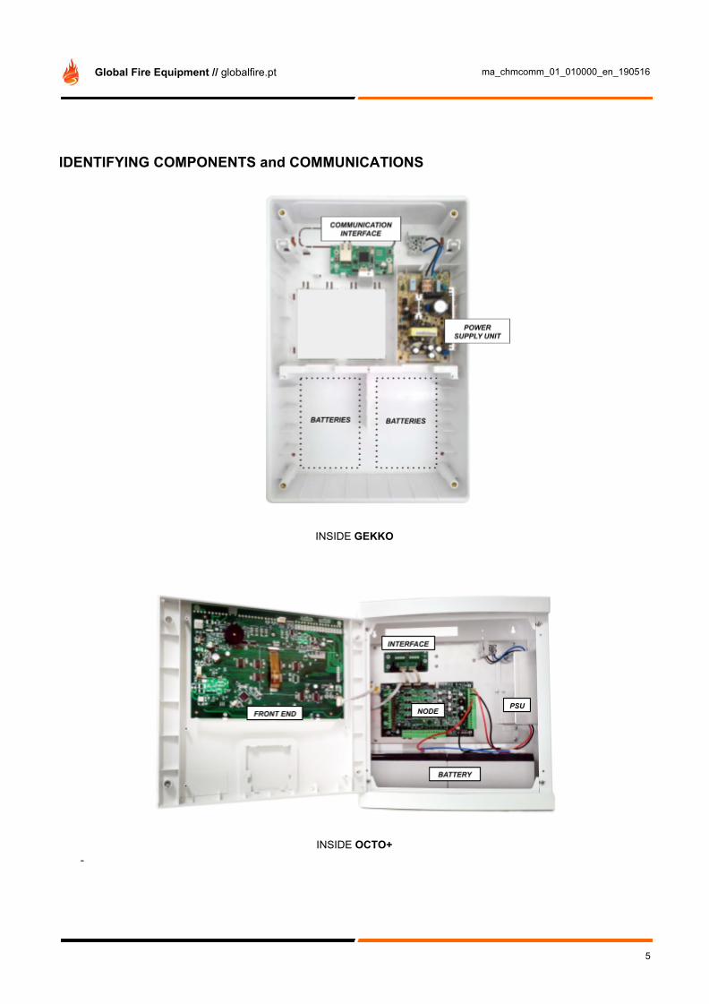
IDENTIFYING COMPONENTS and COMMUNICATIONS
INSIDE GEKKO
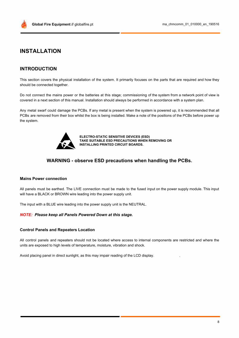
INSIDE OCTO+ -
5

Global Fire Equipment // globalfire.pt ma_chmcomm_01_010000_en_190516
NOTE: ALL CHANNELS (CHx) SHOULD BE CONNECTED THROUGH INTERFACES
6

Global Fire Equipment // globalfire.pt ma_chmcomm_01_010000_en_190516
COMMUNICATION INTERFACES The following interfaces can be used to connect panels or repeaters to a Chameleon Network.
INTERFACE FOR RS422 COMMUNICATION
INT RS422 P2P-D
INT RS422 P2P-S
FIBRE OPTIC INTERFACE
INT FO P2P-D
INT FO P2P-S
INTERFACE FOR TCP/IP COMMUNICATION
INT TCPIP P2P
MIXED INTERFACE
INT RS422 P2P / MIX FO
All Interfaces should be connected to panels using the Flat Cable supplied:
NOTE: Throughout the manual, the red pin on the 5 way molex indicates which pin is nº1. For further interfaces installation or specific details please read the specific interface manual.
7
Global Fire Equipment // globalfire.pt ma_chmcomm_01_010000_en_190516
INSTALLATION
INTRODUCTION This section covers the physical installation of the system. It primarily focuses on the parts that are required and how they should be connected together. Do not connect the mains power or the batteries at this stage; commissioning of the system from a network point of view is covered in a next section of this manual. Installation should always be performed in accordance with a system plan. Any metal swarf could damage the PCBs. If any metal is present when the system is powered up, it is recommended that all PCBs are removed from their box whilst the box is being installed. Make a note of the positions of the PCBs before power up the system.
ELECTRO-STATIC SENSITIVE DEVICES (ESD) TAKE SUITABLE ESD PRECAUTIONS WHEN REMOVING OR INSTALLING PRINTED CIRCUIT BOARDS.
WARNING - observe ESD precautions when handling the PCBs.
Mains Power connection All panels must be earthed. The LIVE connection must be made to the fused input on the power supply module. This input will have a BLACK or BROWN wire leading into the power supply unit. The input with a BLUE wire leading into the power supply unit is the NEUTRAL. NOTE: Please keep all Panels Powered Down at this stage. Control Panels and Repeaters Location All control panels and repeaters should not be located where access to internal components are restricted and where the units are exposed to high levels of temperature, moisture, vibration and shock. Avoid placing panel in direct sunlight, as this may impair reading of the LCD display. .
8
Global Fire Equipment // globalfire.pt ma_chmcomm_01_010000_en_190516
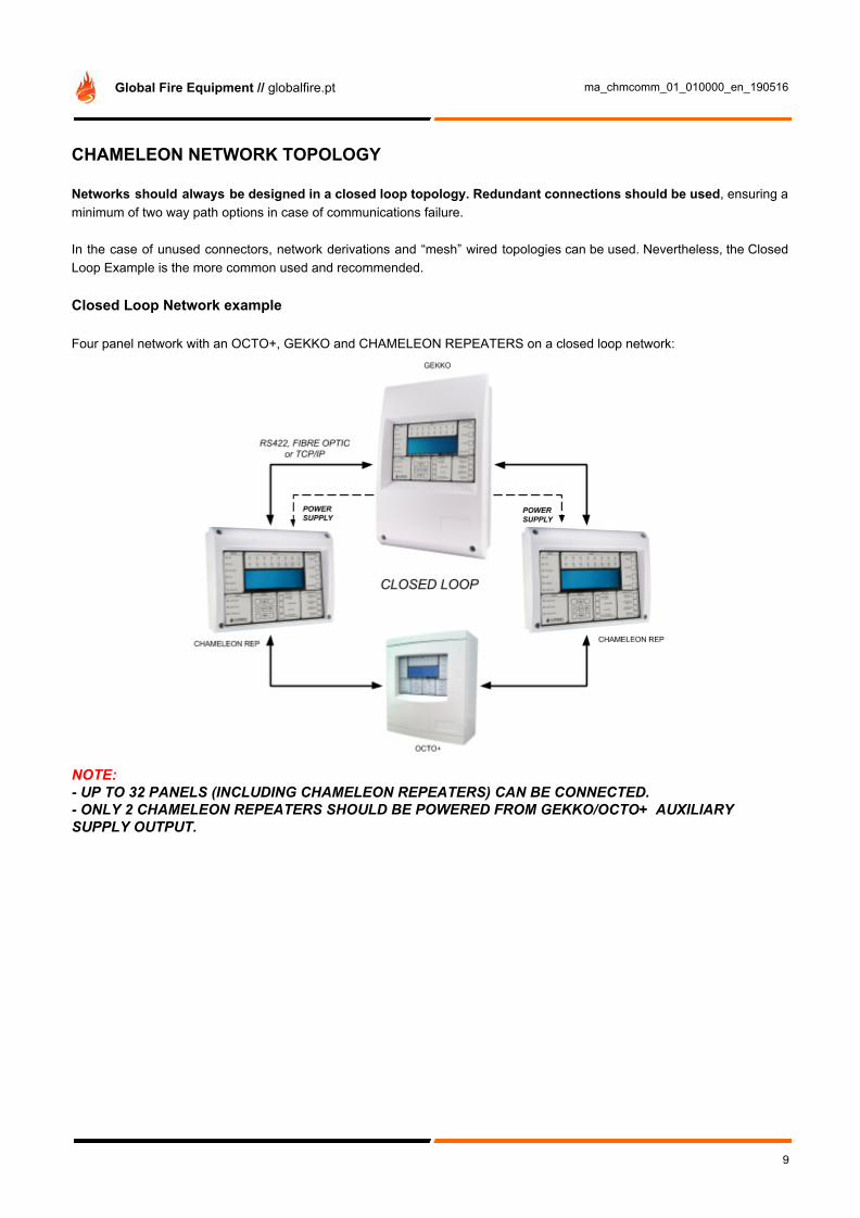
CHAMELEON NETWORK TOPOLOGY Networks should always be designed in a closed loop topology. Redundant connections should be used, ensuring a minimum of two way path options in case of communications failure. In the case of unused connectors, network derivations and “mesh” wired topologies can be used. Nevertheless, the Closed Loop Example is the more common used and recommended. Closed Loop Network example Four panel network with an OCTO+, GEKKO and CHAMELEON REPEATERS on a closed loop network:
NOTE: - UP TO 32 PANELS (INCLUDING CHAMELEON REPEATERS) CAN BE CONNECTED. - ONLY 2 CHAMELEON REPEATERS SHOULD BE POWERED FROM GEKKO/OCTO+ AUXILIARY SUPPLY OUTPUT.
9

Global Fire Equipment // globalfire.pt ma_chmcomm_01_010000_en_190516
Open Loop Network example
NOTE: THIS IS NOT RECOMMENDED!! IT DOES NOT HAVE COMMUNICATIONS REDUNDANCY. Mesh Network example
NOTE: COMMUNICATIONS HIGHLY REDUNDANT (DIFFERENT NETWORK OPTION PATHS).
10

Global Fire Equipment // globalfire.pt ma_chmcomm_01_010000_en_190516
Extended display example (on non networked systems) This example applies only to isolated panels. Non networked panels may need an extra display. In this situation, by applying a Chameleon Display you will have an extension of the Fascia (with a maximum of two). Please do not confuse with Network Addressed Chameleon Repeater panel.
NOTE: - THIS EXAMPLE IS NOT CONSIDERED A CHAMELEON NETWORK - MAXIMUM OF TWO CHAMELEON DISPLAY CAN BE CONNECTED TO A GEKKO - COMPATIBLE WITH GEKKO, OCTO+ or NODE+
11
Global Fire Equipment // globalfire.pt ma_chmcomm_01_010000_en_190516
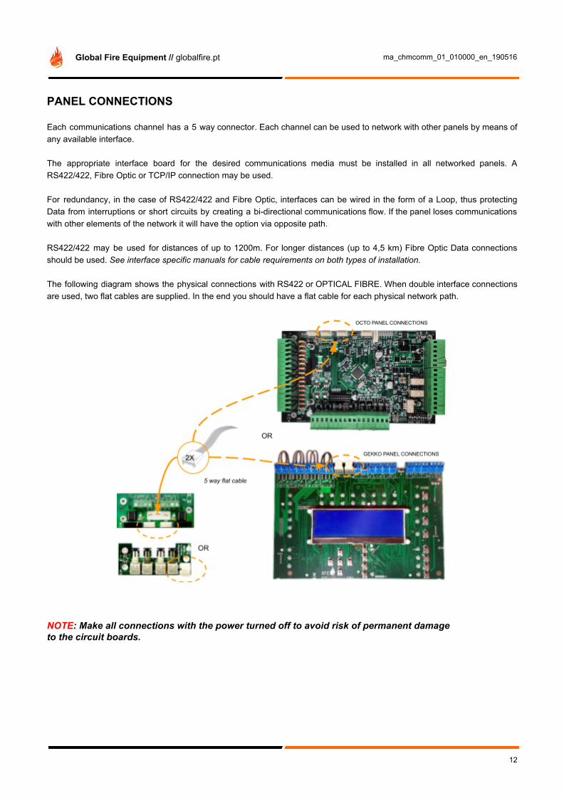
PANEL CONNECTIONS Each communications channel has a 5 way connector. Each channel can be used to network with other panels by means of any available interface. The appropriate interface board for the desired communications media must be installed in all networked panels. A RS422/422, Fibre Optic or TCP/IP connection may be used. For redundancy, in the case of RS422/422 and Fibre Optic, interfaces can be wired in the form of a Loop, thus protecting Data from interruptions or short circuits by creating a bi-directional communications flow. If the panel loses communications with other elements of the network it will have the option via opposite path. RS422/422 may be used for distances of up to 1200m. For longer distances (up to 4,5 km) Fibre Optic Data connections should be used. See interface specific manuals for cable requirements on both types of installation. The following diagram shows the physical connections with RS422 or OPTICAL FIBRE. When double interface connections are used, two flat cables are supplied. In the end you should have a flat cable for each physical network path.
NOTE: Make all connections with the power turned off to avoid risk of permanent damage to the circuit boards.
12

Global Fire Equipment // globalfire.pt ma_chmcomm_01_010000_en_190516
RS422 connections example The following scheme shows how to interconnect two panels with two redundant independent RS422 network paths. This will use 4 flat cables, two “per” panel and two for each physical connection.
RS422 External Connection
The 4 wire external RS422 connections should be made as follows:
FIBRE-OPTIC connections example The following scheme shows how to interconnect two panels with two redundant independent Fibre network paths. This will use 4 flat cables, two “per” panel and two for each physical connection. Connections are made using fibre optic cables instead of copper cables. The ends of the fibre must be terminated with ST™ type Fibre-optic connectors.
Fibre-Optic External Connection
The dual fibre external fibre-optic connections should be made as follows:
13

Global Fire Equipment // globalfire.pt ma_chmcomm_01_010000_en_190516
If more than two panels are connected, the same wiring logic should be applied. Interfaces should all be connected in a daisy chained form (CH2 to next CH1, and finally close loop from last CH2 to first CH1). For further instructions please consult INT 422 or INT FO interface manual. In the following example, a Panel connected with two repeaters is shown, with Fibre Optical in Closed Loop. This will use 6 flat cables, two “per” panel and two for each physical connection. The dual fibre external fibre-optic connections should be made as follows:
If more panels are connected, the same scheme can be applied. Continue to connect CH2 of one Repeater to CH1 of the next Repeater, following the same connection rules as above, until you have reached the last Repeater. When reached the last Repeater, connect CH2 back again to the initial panel, thus “closing the loop”.
14

Global Fire Equipment // globalfire.pt ma_chmcomm_01_010000_en_190516
CHAMELEON REPEATER with double RS422 interface The repeater connections to the RS422 Interface are the same as for the Panel. On the CHAMELEON REP, the flat cable interface connections are different from the GEKKO, as shown below. GEKKO connections are made on the front of PCB and on CHAMELEON REPEATER are made on the back of PCB. Please note that the Repeater does not have a loop card.
NOTE: Make all connections with the power turned off to avoid risk of permanent damage to the circuit boards.
15

Global Fire Equipment // globalfire.pt ma_chmcomm_01_010000_en_190516
Single TCP/IP Peer to Peer Connection The use of a TCP/IP network may require the support and cooperation of the end users’ IT department. Be sure that this support is available before deciding on this communications method. For detailed TCP/IP connections information please refer to TCP/IP specific technical information and/or contact technical support.
INT TCPIP P2P
This interface allows a “Peer to Peer” connection. It is necessary one Interface for each physical link, acting as a serial “point to point” link. NOTE: This is not a double interface. Only one flat cable should be used between the two connectors. If more that one connection link is needed, then another interface should be added. RECOMMENDED CABLES RS422/422 Serial communication cable should be SF/UTP cat.5e grade data cable, eg: FIRETUF 128690NN SF/UTP Cat."5" FB 90 (mbzh) by Draka Fibre-Optic Multi-mode Dual Core sheathed fire proof with 62,5µ/125µ fibre terminated in ST connectors
16

Global Fire Equipment // globalfire.pt ma_chmcomm_01_010000_en_190516
COMMISSIONING
INTRODUCTION Commissioning involves checking that all connections have been properly done and that all hardware is functioning correctly. This means the system must first be installed in accordance with the previous section of this manual. Because of the flexibility and functionality of this panel, it can sometimes be quite hard to establish your desired network configuration, and cause effect actions among networked panels. The basic functionality of the panel is readily available and the fire alarm system will be operational just by supplying it with electrical power. If a fire is detected on any networked panel or an evacuation is set, this action will propagate through the network. The best way to become familiarized with all the programming facilities of this panel will be a hands-on approach, with practical testing, aided closely by both communications manual and panel manual.
GETTING THE PANEL/REPEATER RUNNING Apply AC power to the Panel. The LCD should display the SPLASH SCREEN image with the Panel logo. This will be followed by the date and time (and the company name if it has been set). Within a few seconds faults will be reported, these will overwrite the date and time (and company name). If a Repeater is used, supply can be obtained directly from the auxiliary power supply output of neighbour panel. Apply power to the repeater. If after a few seconds upon completion of the initialization phase the LCD display shows the message "NO COMMS TO PANEL" and the FAULT LED is lit-up, verify the condition of the repeater. Verify the communications and interface connections. The panel is supplied set to ‘Installation mode’. In Installation Mode the green SYSTEM ON LED will flash on and off. The panel will automatically detect and memorize all the devices connected to the loop in the system and all Network connections. The SYSTEM ON LED on the fascia of the panel should be flashing green. This indicates that the system is in Installation Mode. If the LED is solid green the system is in Active Mode and needs to be put into Installation Mode - refer to specific panel manual for further information. If the SYSTEM ON LED is flashing and information is being displayed on the LCD, then the Panel is functional and ready for commissioning. Please refer to “STEP BY STEP” section in order to ensure that all system is running properly. In the end of the commissioning phase, and once the connections and hardware have been checked, it is possible to get the basic fire alarm system up and running very quickly - it is only necessary to have the system in Installation Mode for 90 seconds, then set the system to ‘Active Mode’. During this period the system will record all devices and connections established in order to detect future unwanted changes in the system.
17

Global Fire Equipment // globalfire.pt ma_chmcomm_01_010000_en_190516
NETWORK FUNCTIONS Complete list of functions For communications verification the main functions are highlighted in bold 1 Review Historic Log 1-1 Display Historic Log 1-3 Clear Historic Log 1-5 Read/Clear Autostart Count 3 Zones - Disable & Assign 3-1 Disable Zones 3-2 Assign Sounder Groups to Zones 3-3 Assign I/O Groups to Zones 3-4 Assign Zone to Device 3-5 Zone Sounder Delay Set-up 4 Sounders - Disable & Assign 4-1 Sounder Configuration 4-2 Configure Sounder Groups 4-3 Disable Sounders 4-4 Assign Sounder Group to Device 4-5 Inhibit Sounders for Device 4-6 Sounder Delay Set-up 4-7 Override Sounder Delays 5 Input/Output - Disable & Assign 5-1 Configure I/O Groups 5-2 Select Fault I/O Group 5-3 Assign I/O Group to Device 5-4 Inhibit I/O for Device 5-5 I/O Unit Action upon Evacuate 5-6 I/O Unit Delay or Immediate 5-7 I/O Delay Set-up 6 Device Set-up 6-1 General 6-1-1 Disable Loops 6-1-2 Device Disable 6-1-3 Set Selective Disablement 6-1-4 Set Device Reporting Details 6-1-5 Set Immediate Evacuate for Device 6-1-6 Device Activation Overrides Delays 6-1-7 Inhibit Auxiliary Relays 6-1-8 Global Behaviour Set-up 6-1-9 Configure Timed Behaviour 6-3 Device Specific - Functions only available for panels programmed to ZEOS Protocol 6-3-1 Select Device Behaviour Mode 6-3-2 Flashing LEDs On/Off 6-3-3 Disable Specific Flashing Leds 6-3-4 Re-calibrate All Devices 6-3-5 Check for Devices Needing Service
6-3-6 Read Data Stored in Device 6-3-7 Write Data Stored in Device 6-3-8 Select Device Smoke Sensitivity 6-3-9 Select Device Heat Grade 6-4 Automatic Address Setting 6-4-1 Activate ASET Mode 6-4-2 Clear Loop 6-4-3 Clear Device 7 Monitor Device Counts & Test 7-1 Device Count, Type & Value 7-2 Test Sounders 7-3 Sounders on Test Activation 7-4 Test Zones 7-6 Light LED on device 8 General 8-1 Time/Date & Timers 8-1-1 Set Date & Time 8-1-2 Define Day & Night 8-1-3 Delays Off at Night 8-1-4 Configure Evacuate Timer 8-1-5 Device Starts Evacuate Timer 8-1-7 Configure Extended Delays 8-1-8 Configure Disablement Timer 8-2 Special Features Set-up 8-2-1 Two Devices to Evacuate 8-2-2 Call Points to Evacuate 8-3 Memory - BEWARE, ENGINEERS ONLY 8-3-1 Checksums 8-3-2 Clear Non-Volatile RAM 8-3-3 Calculate Customer Flash Checksum 8-3-4 Calculate Program Flash Checksum 8-4 Other Features 8-4-1 Active/Installation Mode 8-4-4 Set User Access Code 8-4-5 Set User Functions 8-4-6 Select language 8-4-8 Set Installer Access Code 8-4-9 Set Master Access Code 8-5 Network Configuration 8-5-1 Configure Panel Number 8-5-2 Known Panels 8-5-3 Installation Status 8-5-4 Broadcast Configuration 8-5-5 Communication Channels 8-5-6 BMS Setup 8-9 Version Information
18

Global Fire Equipment // globalfire.pt ma_chmcomm_01_010000_en_190516
Specific Network Related Functions 1 Review Historic Log All the functions associated with reviewing or printing events and settings. 1-1 Display Historic Log The panel logs all events in an internal event log. It can store a rolling 10000 entries. When it is full the latest entry is added and the oldest entry discarded. Help is automatically displayed on entry to the function because it is not possible to display a log entry and help at the same time. To select a specific entry, input the number and then press ENTER. 7 Monitor Device Counts & Test 7-1 Device Count, Type & Value Use this function to check that all loop devices are present. Use ▶ 🔺 ▼ to select the device address on that loop. Use ▶ to select the panel Loop. This function is also useful to confirm the address of the various different types of devices connected to the Analogue Loop. Note that in Installation Mode all information is live i.e. the loop “device count”, and “device types” will change as the panel is learning the changes made in the loop. In Active Mode only the device value is live. 8 General 8-1 Time/Date & Timers 8-1-1 Set Date & Time Allows the date and time for the system to be set. The date and time are displayed on the LCD whilst the system is not in fault nor fire. Press ENTER to skip an entry and after each entry. It is important to set the date and time because it is used in the event logging and may also be used to change the detector sensitivities or to disable delays at night. There is only one clock in the system. Setting the date and time at a Repeater is actually setting the SYSTEM clock. NOTE: Removing panel power completely will erase date and time information from panel. Verify that correct date and time information is present after finishing panel commissioning or whenever a timestamp is relevant (ex: device activation testing). 8-3 Memory - BEWARE, ENGINEERS ONLY Programming functions that are associated with management of the Panel memory. 8-3-2 Clear Non-Volatile RAM Clearing the NVRAM clears all the installation settings and the system is automatically put into Installation Mode. . On the Panel this will result in:
● The Analogue Loop will be enabled ● All disabled Zones will be enabled ● All disabled devices will be enabled ● All disabled sounders will be enabled ● The user/installer code will not clear the EVENT LOG.
The EVENT LOG will ONLY be cleared, if Master Code is used. ● The auto-reset count will be cleared ● Information on fitted devices and their types will be cleared ● All checksums will be cleared and recalculated
After clearing the NVRAM it is essential to perform a system Master Reset. 8-4 Other Features These are programming functions that do not fall into any other category.
19

Global Fire Equipment // globalfire.pt ma_chmcomm_01_010000_en_190516
8-4-1 Active/Installation Mode An essential function. The system should always be left in ACTIVE mode, unless the system is being installed and debugged. When the system is set to Installation Mode the green SYSTEM ON LED on the front panel of the Panel and Repeaters will flash. Whilst in Installation Mode, the system will automatically detect and record the presence of all connected devices. To install the system first ensure that all detectors and sounders are connected and have power. Next, select Installation Mode using this function, exit programming mode and press SYSTEM RESET. Once the system has been in Installation Mode for 90 seconds, then the system can be put into Active Mode. Note that there is no clear end to Installation mode because the system is constantly looking and learning. However, if the system is put into Active Mode and Installation Mode hasn’t had time to identify all system components, you will very quickly be greeted with error reports regarding the presence of unexpected devices. If devices are ever removed, replaced or added then Installation Mode must be selected so that the system can learn the new configuration. If you do not do this, the system will report a fault. 8-5 Network Configuration All related with Network configurations and Network Protocols 8-5-1 Configure Panel Number This function allows changing the Panel Network Number (address) This should be unique in the network. NOTE: The Chameleon Rep will need to set an unique Panel Network Number. 8-5-2 Known Panels This function will show how many panels are being recognized and all panel network addresses detected. It will also indicate its own Address on the network. NOTE: This function will only show the panels that are being listened (RX). Meaning that this will only evaluate the receiving transmission path. 8-5-3 Installation Status This function will show the status of the network and error messages. Example: “No nodes detected”. 8-5-4 Broadcast Configuration This function will send the local configuration to all panels in the system. NOTE: - Before running this configuration ensure that the latest configuration is already
uploaded into this panel. - Before running this function please go to each panel in the network and run on each one the 8-5-2
menu and verify that all panels are “seeing” each other and there is no communication issues. - Do not unplug the power during Broadcast. - Do not run this function if you have network issues. - Ensure that the firmware is the same in all panels. 8-5-5 Communication Channels This function shows in which channels data is being received. If the panel has previously received data on a specific channel and no longer listens to messages, meaning that the channel lost the receiving data, then it will signal (ERR). NOTE: Chameleon communications troubleshooting and menus are mostly focused on the “listen/receiving” path. Most of the communications faults are detected by a lost on receiving channel.
20

Global Fire Equipment // globalfire.pt ma_chmcomm_01_010000_en_190516
8-5-6 BMS Setup This function will configure all Building Management System (BMS) Protocols available. The dedicated channel in the GEKKO is the CH2. The Chameleon Panels support the following BMS configuration on the CH2:
BMS PANEL ADDRESS CH2 PROTOCOL SELECTION
TYPE SPECIFIC comments
XX (not applied)
NONE (not applied) CH2 working as a norma Chameleon port
01 to 64
ODYSSEY
(not applied) CH2 working as an ODYSSEY port => with the specified PANEL ADDRESS
XX (not applied)
SHORT MSG
1 CH2 working as “short text” serial port => DECT, no fault ('B'-Alarm / 'V'-PreAlarm)
2 CH2 working as “short text” serial port => DECT, transmit faults ('B'-Alarm / 'V'-PreAlarm / F-Faults)
3 CH2 working as “short text” serial port => SafeTel, no faults ('Al'-Alarm / 'Fo'-PreAlarm)
4 CH2 working as “short text” serial port => SafeTel, transmit faults ('Al'-Alarm / 'Fo'-PreAlarm / 'De'-Device Faults / 'Sy'-System Faults)
8-9 Version Information This function allows the installer to check which software version is running on the current Panel.
21

Global Fire Equipment // globalfire.pt ma_chmcomm_01_010000_en_190516
STEP BY STEP NETWORK COMMISSIONING The following steps must be executed in this specific sequence: NOTE: If Node+ are used in the installation (without display): It is recommended to use a “portable” Chameleon Display during this commissioning phase just to be able to access local panel info. Open network LOOP It is recommended to start with an open loop, or “panel row” topology, connected in a “daisy chained” fashion, ensuring that if some network path is not correct, the connection issue is easily identified. In the end of network commissioning phase, and all checks are made, the loop can be closed again, creating a redundant path. NOTE: Remember to always power down system before disconnecting any interface flat cable channel. Power Up in Installation Mode
1. Ensure all connectors are firmly in place. Ensure that all connections are tight, with no stray strands of wire. 2. Power up the Panel. 3. Ensure that the Panel is in Installation Mode (SYSTEM ON LED flashing). If not, enter programming mode and
select function 8-4-1 Active/Installation Mode and put the panel into Installation Mode. 4. Press SYSTEM RESET.
NOTE: All panels should be in installation mode. If not, a “panel mismatch configuration” fault may be triggered. Please access locally and force that change on each panel 8-4-1 menu. If any fault is triggered after reset please acknowledge by pressing “BUZZER SILENCE” button. If the triggered fault is related with mismatch configuration or communications fault, please ignore and proceed with the “Step-By-Step” commissioning. If any other fault, please refer to specific panel manual and solve the issue before proceeding. Panel Lamp Check In all panels, press and hold LAMP TEST on the Panel. All the LEDs should light, the LCD backlight should turn on and all pixels on the LCD should be black. Check Panel Address On NODE+ and OCTO+ please set a unique address on the dill-switch. On Chameleon REP and GEKKO please go to 8-5-1 Configure Panel Number. Check Panel Version All panels and repeaters should have the same firmware version. Go to function 8-9 Version Information and check if all panels have the same version. If the firmware versions are not the same, please use the Chameleon Connector software tool to download the latest firmware for each panel via MICRO-USB port. This operation has to be executed one by one, firmware broadcast over the network is not supported. Check All Communication Channels (CHx) The installer should check if all wired connections are working as expected. After starting up the system, wait 90 seconds and verify all connection channels report. On each connected panels go to menu 8-5-5 Communication Channels and all “connected” channels should be showing OK. If any of them is not or is displaying an ERR message, then please check connections.
22

Global Fire Equipment // globalfire.pt ma_chmcomm_01_010000_en_190516
NOTE: This menu only evaluates the RX (receiving) input per channel. Meaning that it will only show ERR if, since the last reset, it somehow stopped receiving messages on that specific channel. After a reset, if that specific channel never received any message then “---” will be shown. Check Known Panels After all communication channels are verified and showing OK: On each panel, accessing the menu 8-5-2 Known Panels it’s possible to check the following:
Number of recognized panels: Check if each panel is aware of all other panels Own Panel: Check if the address is the correct one. List of panels: Same as above in a more graphic network view.
This is a very important verification, since it is here where you can check if the panel is not aware of other panels announcements. If some panel is not Listed, please re-check the “non-listed” panel connections. Debug Network messages Please access menu 8-5-3 Installation Status to check local network messages. Example: If no connection is detected, then a “No nodes detected” message is shown. Use this menu to have a system network report. Restart Network Panels Restart a Panel: All network panels should restart as well. Close network LOOP At this stage all panels should be aware of all other panels and all communications channels are displaying OK on the 8-5-5 Menu. Before proceeding with the commissioning, the communications path should now be “closed” creating a redundant two way messages path. Please refer to Network Topology chapter for further info. If panel communication channels are available, more redundant connections can be made (example with NODE+ or OCTO+ there are three channels available per panel). The Chameleon Network support mesh network if extra channels are available. Please repeat the Check All Communications Channels procedure on the new added network path. Upload and Broadcast Configuration to the network Use the Chameleon Connector tool (connected by USB) to upload configuration on one chosen panel. After this a 8-5-4 Broadcast Configuration should be made in order to copy same configuration to all network panels. NOTE: If this step is not correctly done, a “mismatch configuration” error may be shown. Clear NVRAM This is only needed if a “clean installation” setup is desired. Only recommended for “new” installations. Do not perform this on an already installed system! NOTE: - ATTENTION: THE EVENT LOG WILL BE DELETED WITH THIS OPERATION!!! - ALL LOCAL INFO REGARDING STATUS AND NETWORK INFO WILL BE DELETED - THE CUSTOMER CONFIGURATION IS KEPT INTACT. Wait 2 minutes for network recognition If no fault message is shown, then the network system is correctly installed. Change system to Active Mode Go to menu 8-4-1 Active/Installation Mode and switch to active mode
23

Global Fire Equipment // globalfire.pt ma_chmcomm_01_010000_en_190516
Verify remote devices on the installation Go to menu 7-1 Device Count, Type & Value and verify if all devices and panels are correctly being displayed and recognized.
TROUBLESHOOTING “COMMUNICATION FAILURE” NOTE: - Communications failures are only reported by RX (receiving) channel evaluation. - Go to menu 8-5-5 Communication Channels to check connections.
RX connection break on Panel 2 (disconnect RX1 or RX2)
The Panel 2 is no longer receiving in one of the panel channels (could be either CH1->RX1 or CH2->RX2). The following messages will be shown:
Panel 1 Panel 2 Panel 3
PANEL 02 COMMUNICATION FAILURE
TOTAL NUMBER OF FAULTS 0001
PANEL 02 COMMUNICATION FAILURE
TOTAL NUMBER OF FAULTS 0001
PANEL 02 COMMUNICATION FAILURE
TOTAL NUMBER OF FAULTS 0001
24

Global Fire Equipment // globalfire.pt ma_chmcomm_01_010000_en_190516
TX1 connection break on Panel 2
The Panel 1 is no longer receiving in one of the channels (CH2-> RX2). The following messages will be shown:
Panel 1 Panel 2 Panel 3
PANEL 01 COMMUNICATION FAILURE
TOTAL NUMBER OF FAULTS 0001
PANEL 01 COMMUNICATION FAILURE
TOTAL NUMBER OF FAULTS 0001
PANEL 01 COMMUNICATION FAILURE
TOTAL NUMBER OF FAULTS 0001
TX2 connection break on Panel 2
The Panel 3 is no longer receiving in one of the channels (CH1-> RX1). The following messages will be shown:
Panel 1 Panel 2 Panel 3
PANEL 03 COMMUNICATION FAILURE
TOTAL NUMBER OF FAULTS 0001
PANEL 03 COMMUNICATION FAILURE
TOTAL NUMBER OF FAULTS 0001
PANEL 03 COMMUNICATION FAILURE
TOTAL NUMBER OF FAULTS 0001
25

Global Fire Equipment // globalfire.pt ma_chmcomm_01_010000_en_190516
“PANEL CONFIGURATION MISMATCH” One Panel in ACTIVE MODE and all other in INSTALLATION MODE
The Panel 1, due to a failure on the network, has changed to Installation mode and the others have not. All panels will trigger “Panel Configuration Mismatch” on Panel 1. Panel 1 will trigger the fault mentioning all other panels on the queue.
Panel 1 Panel 2 Panel 3
PANEL 02 PANEL CONFIGURATION MISMATCH
TOTAL NUMBER OF FAULTS 0002
PANEL 01 PANEL CONFIGURATION MISMATCH
TOTAL NUMBER OF FAULTS 0001
PANEL 01 PANEL CONFIGURATION MISMATCH
TOTAL NUMBER OF FAULTS 0001
PANEL 03 PANEL CONFIGURATION MISMATCH
TOTAL NUMBER OF FAULTS 0002
26

Global Fire Equipment // globalfire.pt ma_chmcomm_01_010000_en_190516
Upload a configuration without broadcast
The Panel 1, due to USB Chameleon Connector Config Update, changed the local configuration and the configuration was not broadcasted to other system panels. All panels will trigger “Panel Configuration Mismatch” on Panel 1. Panel 1 will trigger the fault mentioning all other panels on the queue. After an USB Config Update the menu 8-5-4 Broadcast Configuration should be executed in order to copy same configuration to all network panels. The following errors should be mentioned on the panels:
Panel 1 Panel 2 Panel 3
PANEL 02 PANEL CONFIGURATION MISMATCH
TOTAL NUMBER OF FAULTS 0002
PANEL 01 PANEL CONFIGURATION MISMATCH
TOTAL NUMBER OF FAULTS 0001
PANEL 01 PANEL CONFIGURATION MISMATCH
TOTAL NUMBER OF FAULTS 0001
PANEL 03 PANEL CONFIGURATION MISMATCH
TOTAL NUMBER OF FAULTS 0002
27
Global Fire Equipment // globalfire.pt ma_chmcomm_01_010000_en_190516
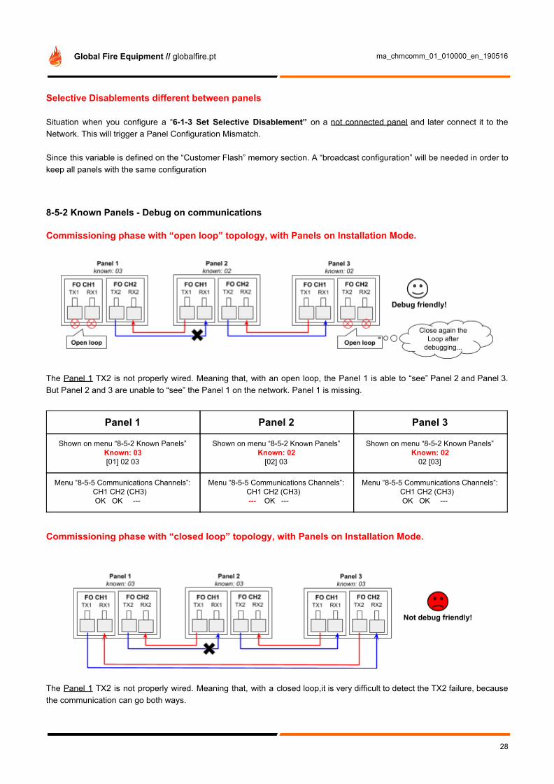
Selective Disablements different between panels Situation when you configure a “6-1-3 Set Selective Disablement” on a not connected panel and later connect it to the Network. This will trigger a Panel Configuration Mismatch. Since this variable is defined on the “Customer Flash” memory section. A “broadcast configuration” will be needed in order to keep all panels with the same configuration 8-5-2 Known Panels - Debug on communications Commissioning phase with “open loop” topology, with Panels on Installation Mode.
The Panel 1 TX2 is not properly wired. Meaning that, with an open loop, the Panel 1 is able to “see” Panel 2 and Panel 3. But Panel 2 and 3 are unable to “see” the Panel 1 on the network. Panel 1 is missing.
Panel 1 Panel 2 Panel 3
Shown on menu “8-5-2 Known Panels” Known: 03 [01] 02 03
Shown on menu “8-5-2 Known Panels” Known: 02
[02] 03
Shown on menu “8-5-2 Known Panels” Known: 02
02 [03]
Menu “8-5-5 Communications Channels”: CH1 CH2 (CH3) OK OK ---
Menu “8-5-5 Communications Channels”: CH1 CH2 (CH3) --- OK ---
Menu “8-5-5 Communications Channels”: CH1 CH2 (CH3) OK OK ---
Commissioning phase with “closed loop” topology, with Panels on Installation Mode.
The Panel 1 TX2 is not properly wired. Meaning that, with a closed loop,it is very difficult to detect the TX2 failure, because the communication can go both ways.
28

Global Fire Equipment // globalfire.pt ma_chmcomm_01_010000_en_190516
Panel 1 Panel 2 Panel 3
Shown on menu “8-5-2 Known Panels” Known: 03 [01] 02 03
Shown on menu “8-5-2 Known Panels” Known: 03 01 [02] 03
Shown on menu “8-5-2 Known Panels” Known: 03 01 02 [03]
Menu “8-5-5 Communications Channels”: CH1 CH2 (CH3) OK OK ---
Menu “8-5-5 Communications Channels”: CH1 CH2 (CH3) --- OK ---
Menu “8-5-5 Communications Channels”: CH1 CH2 (CH3) OK OK ---
GLOBAL FIRE EQUIPMENT S.A.
Sítio dos Barrabés, Armazém Nave Y, Caixa Postal 908-Z, 8150-016 São Brás de Alportel - PORTUGAL Tel: +351 289 896 560 • Sales: [email protected] • Technical Support: [email protected] • www.globalfire.pt
29


![Chameleon [Chattaway]](https://img.pdfslide.net/doc/110x75/55cf9050550346703ba4cf63/chameleon-chattaway.jpg)