Embed Size (px)
Citation preview

CHANGE HEADQUARTERS DEPARTMENT OF THE ARMY NO. 1 WASHINGTON, D.C., 28 May 2007
TRAINING CIRCULAR
AIRCREW TRAINING MANUAL
ATTACK HELICOPTER AH-64D
TC 1-251, 14 September 2005, is changed as follows:
1. Remove old pages and insert new pages as indicated below. New or changed material is indicated by a vertical bar in the margin of the page.
Remove pages Insert pages ----- A through B i through vi i through vii 1-1 1-1
2-1 through 2-11 2-1 through 2-11 4-1 through 4-8 4-1 through 4-8 4-61 through 4-62 4-61 through 4-62 4-65 through 4-68 4-65 through 4-68 4-71 4-71 4-73 through 4-80 4-73 through 4-80 4-91 through 4-92 4-91 through 4-92 4-99 through 4-104 4-99 through 4-104 4-107 through 4-110 4-107 through 4-110 4-131 through 4-136 4-131 through 4-136 4-147 through 4-148 4-147 through 4-148 4-155 through 4-158 4-155 through 4-161 ----- 4-161.0 through 4-161.5 4-162 4-162 4-165 through 4-167 4-165 through 4-167 ----- 4-167.0 through 4-167.1 4-168 through 4-174 4-168 through 4-174 4-183 through 4-194 4-183 through 4-194 4-213 through 4-216 4-213 through 4-216 ----- 4-216.1 through 4-216.2 4-221 through 4-228 4-221 through 4-228 ----- 4-228.1 through 4-228.3 4-243 through 4-256 4-243 through 4-256.4 ----- 4-263 through 4-264 5-3 through 5-8 5-3 through 5-8 5-13 through 5-14 5-13 through 5-14 5-23 through 5-32 5-23 through 5-32

Remove pages Insert pages 5-35 through 5-38 5-35 through 5-38 5-41 through 5-42 5-41 through 5-42 6-5 through 6-8 6-5 through 6-8 ----- A-1 through A-2 ----- B-1 through B-2 Index-1 Index-1
2. File this change sheet in the front of the publication for reference purposes. By the order of the Secretary of the Army:
GEORGE W. CASEY, JR. General, United States Army
Chief of Staff Official:
JOYCE E. MORROW
Administrative Assistant to the Secretary of the Army
0713401
This publication is available at Army Knowledge Online (www.us.army.mil) and General Dennis J. Reimer Training and Doctrine
Digital Library at (www.train.army.mil).

TC 1-251 C1
28 May 2007 A
INSERT LATEST CHANGED PAGES: DESTROY SUPERSEDED PAGES.
NOTE: The portion of the text affected by the changes is indicated by a vertical line in the outer margins of the page. Changes to illustrations are indicated by miniature pointing hands. Changes to wiring diagrams are indicated by shaded areas.
Date of issue for original and change pages are—
Original ….…………0………….14 September 2005 Change……..……..…...1……........……28 May 2007
TOTAL NUMBER OF PAGES IN THIS PUBLICATION IS 376 CONSISTING OF THE FOLLOWING:
PAGE NO.
*CHANGENo.
PAGE NO.
*CHANGENo.
Cover…………….......................... ....................... 0 4-107 - 4-110......…………..…………………..…. 1
Publication Internet Listing………………………… 0 4-111 - 4-130.......…………..……………………. 0
A – B…………………………………………………. 1 4-131 - 4-136.......…………..……………………. 1
i – vi………………………………………………...... 1 4-137 - 4-146.......…………..……………………. 0
vii Added…………………………………………….. 1 4-147 - 4-148.......…………..……………………. 1
viii Blank Added………………………………….… 1 4-149 - 4-154.......…………..……………………. 0
1-1 – 1-2 Blank…………………………………….. 1 4-155 - 4-161.......…………..……………………. 1
2-1 – 2-12 Blank….………………………………… 1 4-161.0 - 4-161.5 Added....……………………. 1
3-1 – 3-8…………………………………………….. 0 4-163 - 4-164.......…………..……………………. 0
4-1 – 4-8…………………………………………….. 1 4-165 - 4-167.......…………..……………………. 1
4-9 – 4-60………………………………………….... 0 4-167.1 – 4-167.2…………..……………………. 1
4-61 – 4-62………………………………………….. 1 4-168 - 4-174….....…………..…………………… 1
4-63 – 4-64………………………………………….. 0 4-175 - 4-182.......…………………………………. 0
4-65 – 4-68…………………………………….……. 1 4-183 - 4-194.......…………………………………. 1
4-69 – 4-70.…………………………………….…… 0 4-195 - 4-212.......…………………………………. 0
4-71 – 4-80……………………………………….…. 1 4-213 - 4-216.......…………………………………. 1
4-81 – 4-90………………………………………….. 0 4-216.1 - 4-216.2 Added...….……………………. 1
4-91 – 4-92………………………………….………. 1 4-217 - 4-220.......…………………………………. 0
4-93 – 4-98………………………………….………. 0 4-221 - 4-228.......…………………………………. 1
4-99 – 4-104………………..………………………. 1 4-228.1 - 4-228.4 Added...….……………………. 1
4-105 - 4-106.......…………..…………………..…. 0 4-229 - 4-242.......…………………………………. 0
*Zero in this column indicates an original page.
LIST OF EFFECTIVE PAGES

TC 1-251 C1
B 28 May 2007
INSERT LATEST CHANGED PAGES: DESTROY SUPERSEDED PAGES.
PAGE NO.
*CHANGENo.
PAGE NO.
*CHANGENo.
4-243 - 4-248.......…………………………………. 1 5-33 – 5-34……………………………………….. 0
4-249 - 4-256…....…………………………………. 1 5-35 – 5-38……………………………………….. 1
4-256.1 - 4-256.4 Added...….……….……………. 1 5-39 – 5-40……………………………………….. 0
4-257 - 4-262.......…………………………………. 0 5-41 – 5-42……………………………………….. 1
4-263 – 4-264 Added…......….……………………. 1 5-43 – 6-4..……………………………………….. 0
5-1 – 5-2 …….…………………………………….. 0 6-5 – 6-8……………………………………………. 1
5-3 – 5-8 …….…………………………………….. 1 A-1 – A-2 Added…….…………………………….. 1
5-9 – 5-12…….…………………………………….. 0 B-1 – B-2 Added……………………….………….. 1
5-13 – 5-14………………………………………….. 1 Glossary-1– Glossary-14…………….………….... 0
5-15 – 5-22………………………………………….. 0 References-1– References-4….……..………..... 0
5-23 – 5-32………………………………………….. 1 Index-1 ……………………………………………. 1
Back Cover………………………………………… 0
*Zero in this column indicates an original page.
LIST OF EFFECTIVE PAGES

TC 1-251 C1
28 May 2007 i
Training Circular No. TC 1-251
Headquarters Department of the Army
Washington, DC, 28 May 2007
AIRCREW TRAINING MANUAL ATTACK HELICOPTER, AH-64D
Contents Page
PREFACE ............................................................................................... vii Chapter 1 Introduction .......................................................................................... 1-1
1-1. Crew Station Designation................................................................ 1-1 1-2. Symbol Usage and Word Distinctions............................................. 1-1
Chapter 2 Training ................................................................................................. 2-1 2-1. Qualification Training ...................................................................... 2-1 2-2. Refresher Training .......................................................................... 2-2 2-3. Mission Training .............................................................................. 2-2 2-4. Continuation Training ...................................................................... 2-4 2-5. Task List .......................................................................................... 2-5 2-6. Currency Requirements .................................................................. 2-1 2-7. Chemical, Biological, Radiological, and Nuclear Training Requirements ....................................................................................... 2-11
Chapter 3 Evaluations ........................................................................................... 3-1 3-1. Evaluation Principles....................................................................... 3-1 3-2. Grading Considerations .................................................................. 3-2 3-3. Crewmember Evaluation................................................................. 3-2 3-4. Evaluation Sequence ...................................................................... 3-3
Chapter 4 Crewmember Tasks ............................................................................. 4-1 4-1. Task Contents ................................................................................. 4-1 4-2. Tasks............................................................................................ 4-7.0
Chapter 5 Maintenance Test Pilot Tasks ............................................................. 5-1 5-1. Task Contents ................................................................................ 5-1
5-2. Tasks........................................................................................ … 5-3
____________________________________________________________________________ Distribution Restriction: Approved for public release; distribution is unlimited.

TC 1-251 C1
ii 28 May 2007
Chapter 6 Crew Coordination ............................................................................... 6-1 6-1. Crew Coordination Background ...................................................... 6-1 6-2. Crew Coordination Elements........................................................... 6-1 6-3. Crew Coordination Basic Qualities.................................................. 6-2 6-4. Crew Coordination Objectives......................................................... 6-6 6-5. Standard Crew Terminology ........................................................... 6-6
Appendix A Symbology Display Unit ..................................................................... A-1 Appendix B MTADS/MPNVS.................................................................................... B-1 Glossary ...................................................................................Glossary-1
References ...........................................................................References-1
Index ...............................................................................................Index-1
Tasks Task 1000 Participate in a Crew Mission Briefing..........................................................4-8 Task 1004 Plan a Visual Flight Rules Flight.................................................................4-12 Task 1006 Plan an Instrument Flight Rules Flight........................................................4-14 Task 1010 Prepare a Performance Planning Card ......................................................4-16 Task 1012 Verify Aircraft Weight and Balance.............................................................4-28 Task 1013 Operate Mission Planning System .............................................................4-29 Task 1014 Operate Aviation Life Support Equipment ..................................................4-31 Task 1022 Perform Preflight Inspection .......................................................................4-32 Task 1024 Perform Before Starting Engine Through Before Leaving Helicopter Checks .4-33 TASK 1026 MAINTAIN AIRSPACE SURVEILLANCE...................................................4-35 TASK 1028 PERFORM HOVER POWER CHECK........................................................4-37 Task 1032 Perform Radio Communications Procedures .............................................4-39 TASK 1034 PERFORM GROUND TAXI........................................................................4-40 TASK 1038 PERFORM HOVERING FLIGHT................................................................4-43 TASK 1040 PERFORM VISUAL METEOROLOGICAL CONDITIONS TAKEOFF........4-47 TASK 1041 PERFORM TRAFFIC PATTERN FLIGHT………….............…………... .....4-52 TASK 1044 NAVIGATE BY PILOTAGE AND DEAD RECKONING………..……… ......4-54 Task 1046 Perform Electronically Aided Navigation ....................................................4-55 Task 1048 Perform Fuel Management Procedures .....................................................4-57 TASK 1050 PERFORM HIGH SPEED FLIGHT.............................................................4-59 TASK 1056 PERFORM HIGH/LOW G FLIGHT.............................................................4-60 TASK 1058 PERFORM VISUAL METEOROLOGICAL CONDITIONS APPROACH ....4-62 TASK 1062 PERFORM SLOPE OPERATIONS............................................................4-66 TASK 1064 PERFORM A ROLL-ON LANDING ............................................................4-68 Task 1070 Respond to Emergencies ...........................................................................4-70 TASK 1072 RESPOND TO ENGINE FAILURE, IN-GROUND EFFECT HOVER .........4-71 TASK 1073 RESPOND TO ENGINE FAILURE, OUT-OF-GROUND EFFECT
HOVER……………………………………………………………………… .....4-73

TC 1-251 C1
28 May 2007 iii
TASK 1074 RESPOND TO ENGINE FAILURE AT CRUISE FLIGHT……………… .....4-75 TASK 1075 PERFORM SINGLE-ENGINE LANDING .................................................. 4-77 TASK 1082 PERFORM AUTOROTATION....................................................................4-79 TASK 1085 PERFORM STABILITY AND COMMAND AUGMENTATION SYSTEM-
OFF/BACKUP CONTROL SYSTEM-ON FLIGHT......................................4-82 TASK 1110 PERFORM ELECTRONIC CONTROL UNIT/DIGITAL ELECTRONIC CONTROL UNIT LOCKOUT PROCEDURES…………………………........4-84 TASK 1114 PERFORM ROLLING TAKEOFF ...............................................................4-86 Task 1116 Perform Tactical Situation Display Operations ...........................................4-89 Task 1122 Perform Target Store Procedures ..............................................................4-90 Task 1132 Perform Integrated Helmet and Display Sight System Boresight ...............4-91 Task 1133 Perform Aircraft Position Update Function .................................................4-92 Task 1134 Perform Integrated Helmet and Display Sight System Operations.............4-94 Task 1135 Perform Integrated Helmet and Display Sight System Video Adjustments .....4-97 Task 1138 Perform Target Acquisition and Designation Sight Boresight…………... .4-100 Task 1139 Perform Target Acquisition and Designation Sight Operational Checks ..4-102 Task 1140 Perform Target Acquisition and Designation Sight Sensor Operation......4-103 Task 1142 Perform Digital Communications..............................................................4-105 Task 1143 Perform Fire Control Radar Operational Checks......................................4-106 Task 1144 Perform Fire Control Radar Operations....................................................4-107 Task 1148 Perform Data Management Operations....................................................4-110 TASK 1155 NEGOTIATE WIRE OPSTACLES............................................................4-111 Task 1160 Operate Video Recorder ..........................................................................4-113 Task 1170 Perform Instrument Takeoff......................................................................4-116 Task 1172 Perform Radio Navigation ........................................................................4-118 Task 1174 Perform Holding Procedures ....................................................................4-120 Task 1176 Perform Nonprecision Approach ..............................................................4-122 Task 1178 Perform Precision Approach ....................................................................4-124 Task 1180 Perform Emergency Global Positioning System Recovery Procedure.....4-126 TASK 1182 PERFORM UNUSUAL ATTITUDE RECOVERY......................................4-128 TASK 1184 RESPOND TO INADVERTENT INSTRUMENT METEOROLOGICAL
CONDITIONS…………………………………………………………… ........4-130 Task 1188 Operate Aircraft Survivability Equipment..................................................4-132 Task 1194 Perform Refueling/Rearming Operations .................................................4-135 Task 1262 Participate in A Crew Level After-Action Review......................................4-137 Task 1402 Perform Tactical Flight Mission Planning .................................................4-139 Task 1404 Perform Electronic Countermeasures/Electronic Counter-Countermeasures
Procedures ...............................................................................................4-141 Task 1405 Transmit Tactical Reports (Digital/Voice) .................................................4-143 TASK 1406 PERFORM TERRAIN FLIGHT NAVIGATION..........................................4-146 TASK 1407 PERFORM TERRAIN FLIGHT TAKEOFF ...............................................4-148 TASK 1408 PERFORM TERRAIN FLIGHT.................................................................4-150 TASK 1409 PERFORM TERRAIN FLIGHT APPROACH............................................4-153 TASK 1410 PERFORM MASKING AND UNMASKING...............................................4-155

TC 1-251 C1
iv 28 May 2007
TASK 1411 PERFORM TERRAIN FLIGHT DECELERATION....................................4-158 TASK 1412 PERFORM EVASIVE MANEUVERS .......................................................4-160 TASK 1413 PERFORM ACTIONS ON CONTACT......................................................4-162 TASK 1414 PERFORM FIRING POSITION OPERATIONS........................................4-163 TASK 1415 PERFORM DIVING FLIGHT ...................................................................4-166 Task 1416 Perform Weapon Initialization Procedures ...............................................4-168 TASK 1422 PERFORM FIRING TECHNIQUES..........................................................4-170 Task 1458 Engage Target With Point Target Weapons System................................4-174 Task 1462 Engage Target With Rockets ...................................................................4-194 Task 1464 Engage Target With Area Weapon System..............................................4-201 Task 1469 Perform Area Weapon System Dynamic Harmonization..........................4-206 TASK 1470 PERFORM TARGET HANDOVER...........................................................4-208 Task 1835 Perform Night Vision System Operational Checks ...................................4-211 TASK 2010 PERFORM MULTI-AIRCRAFT OPERATIONS........................................4-214 Task 2013 Perform Tactical Fire Computer Airborne Target Handover System Air/Transfer Mode Operations......................................................................................4-217 TASK 2042 PERFORM TEAM EMPLOYMENT TECHNIQUES..................................4-218 TASK 2045 OPERATE THE IR ZOOM LASER ILLUMINATOR-DESIGNATOR (IZLID) 1000P-W LASER..........................................................................4-222 Task 2050 Develop an Emergency GPS Recovery Procedure………….…………… 4-225 Task 2066 Perform Extended Range Fuel System Procedures.................................4-229 TASK 2068 PERFORM SHIPBOARD OPERATIONS.................................................4-234 TASK 2081 OPERATE NIGHT CISION GOGGLES....................................................4-242 TASK 2127 PERFORM COMBAT MANEUVERING FLIGHT......................................4-244 TASK 2130 PERFORM CLOSE COMBAT ATTACK...................................................4-249 Task 2162 Call For Indirect Fire.................................................................................4-253 Task 2164 Call For a Tactical Air Strike.....................................................................4-257 TASK 2170 OPERATE NIGHT VISION GOGGLES WITH THE SDU (SYMBOLOGY
DISPLAY UNIT) ATTACHED ...................................................................4-263 Task 4000 Perform Prior to Maintenance Test Flight Checks............. ......................5-4 Task 4001 Perform a Maintenance Operational Check/Maintenance Test Flight
Crewmember Brief.........................................................................................5-5 Task 4004 Perform Interior Checks ............................................................................... 5-9 Task 4008 Perform Before Starting Auxiliary Power Unit Checks................................ 5-10 Task 4010 Perform Starting Auxiliary Power Checks... ...........................................5-11 Task 4012 Perform After-Starting Auxiliary Power Unit Checks................................. ..5-12 Task 4088 Perform Starting Engine Checks................................................................ .5-15 Task 4090 Perform Engine Run-Up and Systems Checks…........................................5-16 Task 4110 Perform Before Taxi Checks....................................................................... 5-17 TASK 4112 PERFORM TAXI CHECKS......................................................................... 5-18 Task 4114 Perform Baseline and Normal Engine Health Indicator Checks..................5-20 Task 4123 Perform Before Hover Checks.................................................................... 5-21 TASK 4144 PERFORM HOVER CHECKS.....................................................................5-22 TASK 4160 PERFORM HOVER MANEUVERING CHECKS ...................................5-23 TASK 4162 PERFORM FLIGHT MANAGEMENT COMPUTER/ATTITUDE HOLD CHECKS ...............................................................................................5-24 TASK 4182 PERFORM VISIONIC SYSTEMS CHECKS............................................... 5-25

TC 1-251 C1
28 May 2007 v
TASK 4184 PERFORM HOVER BOX DRIFT CHECK ……...........................................5-26 TASK 4208 PERFORM INITIAL TAKEOFF CHECK………............................................5-27 Task 4220 Perform Maximum Power Check ................................................................5-28 Task 4221 Perform Maximum Power Check-Non-Limiting Method.............................. 5-31 TASK 4222 PERFORM CRUISE FLIGHT CHECKS ..................................................... 5-33 TASK 4236 PERFORM AUTOROTATION REVOLUTIONS PER MINUTE CHECK 5-34 TASK 4238 PERFORM ATTITUDE HOLD CHECK……................................................5-37 TASK 4240 PERFORM MANEUVERING-FLIGHT CHECKS……. ................................5-38 TASK 4242 PERFORM STABILATOR SYSTEM CHECK............................................. 5-39 Task 4258 Determine Turbine Gas Temperature Setting/Contingency Power……......5-40 Task 4262 Perform Communication and Navigation Checks.......................................5-41.1 Task 4264 Perform Sight/Sensor Checks…… .............................................................5-43 Task 4266 Perform Weapon Systems Checks............................................................. 5-44 Task 4276 Perform Special/Detailed Procedures........................................................ 5-45 Task 4284 Perform Engine Shutdown Checks............................................................ 5-46 TASK 4292 PERFORM Vh CHECK………………………............................................... 5-47
Figures Figure 4-1. Sample DA Form 5701-64-R (front). .............................................4-26 Figure 4-2. Sample DA Form 5701-64-R (back)..............................................4-27 Figure 4-3. Sample crew debrief. ..................................................................4-138 Figure 4-4. Race track pattern.......................................................................4-219 Figure 4-5. Clover leaf pattern.......................................................................4-220 Figure 4-6. Figure 8 pattern...........................................................................4-220 Figure 4-7. L–pattern. ....................................................................................4-221 Figure 4-8 Final approach fix altitude ........................................................4-228.1 Figure 4-8(a). Initial approach fix ...................................................................4-228.1 Figure 4-8(b). Minimum descent altitude ........................................................4-228.2 Figure 4-8(c). Missed approach obstacle clearance.......................................4-228.2 Figure 4-8(d). Sample GPS approach ............................................................4-228.3 Figure 4-9. Close combat attack briefing.......................................................4-251 Figure 4-10. Sample remote hellfire request–voice. .....................................4-256.1 Figure 4-10(a). Hellfire remote-Engagement safety fan chart...........................4-256.2 Figure 4-10(b). Hellfire Remote-engagement safety fan chart..........................4-256.3 Figure 4-11. CAS check-in briefing..................................................................4-259 Figure 4-12. CAS briefing. ...............................................................................4-260

TC 1-251 C1
vi 28 May 2007
Tables Table 2-1. Refresher flight training hours .............................................................2-2 Table 2-2 Mission flight training hours .................................................................2-3 Table 2-3 Maintenance test pilot/maintenace examiner flight training hours .... .. 2-4 Table 2-4 Aviator base task list............................................................................2-5 Table 2-5. Aviator mission task list. ......................................................................2-9 Table 2-6. Maintenance test pilot task list...........................................................2-10 Table 4-1 MAHF Altitude Calculation Table.....................................................4-226 Table 4-1.1 MSA calculation table ......................................................................4-227 Table 4-1.2 Landing visibility minimums based on height above landing ..........4-227 Table 4-2 Step 1–Determine weight and moment of pylon stores loading. .....4-231 Table 4-2 Step 2–Determine the aircraft lateral center of gravity. ...................4-231 Table 4-4. Timing options .................................................................................4-261 Table 6-1. Examples of standard words and phrases ..........................................6-6

TC 1-251 C1
28 May 2007 vii
Preface
The aircrew training manual (ATM) standardizes aircrew training programs and flight evaluation procedures. This manual provides specific guidelines for executing AH-64D aircrew training. It is based on the battle-focused training principles outlined in FM 7-1. It establishes crewmember qualification, refresher, mission, continuation training, and evaluation requirements. This manual applies to all AH-64D crewmembers and their commanders. This is not a stand-alone document. All of the requirements of AR 600-105, AR 600-106, NGR 95-210, and TC 1-210 must be met. Implementation of this manual conforms to AR 95-1 and TC 1-210. If differences exist between the maneuver descriptions in TM 1-1520-251-10 and this manual, this manual is the governing authority for training and flight evaluation purposes. This manual (in conjunction with the ARs and TC 1-210) will help aviation commanders at all levels to develop a comprehensive aircrew training program. By using this ATM, commanders ensure that individual crewmember and aircrew proficiency is commensurate with the unit mission and that aircrews routinely employ standard techniques and procedures. Crewmembers will use this manual as a “how to” source for performing crewmember duties. It provides performance standards and evaluation guidelines so crewmembers know the level of performance expected. Each task has a description of a technique that may be performed to safely meet the standard. Standardization officers, evaluators, and unit trainers will use this manual and TC 1-210 as the primary tools to assist the commander to develop and implement his aircrew training program. This manual applies to the Active Army, the Army National Guard (ARNG)/Army National Guard of the United States (ARNGUS), and the U.S. Army Reserve (USAR) unless otherwise stated. The proponent of this publication is United States Army Training and Doctrine Command (TRADOC). Send comments and recommendations on DA Form 2028 (Recommended Changes to Publications and Blank Forms) through the aviation unit commander to Commander, U.S. Army Aviation Warfighting Center, ATTN: ATZQ-ES (Attack Section), Building 4503 Kingsman Avenue, Fort Rucker, Alabama 36362-5263. Recommended changes may also be e-mailed to [email protected]. This publication implements portions of STANAG 3114 (Edition Seven). Unless this publication states otherwise, masculine nouns and pronouns do not refer exclusively to men. This publication has been reviewed for operations security considerations.

This page intentionally left blank.

TC 1-251 C1
28 May 2007 1-1
Chapter 1
Introduction This ATM describes training requirements for crewmembers. It will be used with AR 95-1, AR 600-105, AR 600-106, NGR 95-210, TC 1-210, and other applicable publications. The tasks in this ATM enhance training in individual and aircrew proficiency. The training focuses on the accomplishment of tasks supporting the unit’s mission. The scope and level of training to be achieved individually by crewmembers and collectively by aircrews will be dictated by the mission essential task list (METL). Commanders must ensure that aircrews are proficient in mission-essential tasks.
1-1. CREW STATION DESIGNATION. The commander will designate a crew station(s) for each crewmember. The commander’s task list must clearly indicate all crew station designations. Training and proficiency sustainment is required in each designated crew station. Instructor pilots (IPs), standardization instructor pilots (SPs), instrument examiners (IEs), and maintenance examiners (MEs) must maintain proficiency in both seats. Commanders may designate unit trainers (UTs), maintenance pilots (MPs), selected pilots-in-command (PCs) and pilots as dual-station crewmembers. Aviators designated to fly from both stations will be evaluated in each seat during annual proficiency and readiness training (APART) evaluations including dual-seat designated flight activity category (FAC) 3. This does not mean that all tasks must be evaluated in each seat.
1-2. SYMBOL USAGE AND WORD DISTINCTIONS.
a. Symbol usage. The diagonal (/) indicates “and,” “or,” or both. For example, IP/SP may mean IP and SP or may mean IP or SP.
b. Word distinctions. (1) Warning, caution, and note. These words emphasize important and critical instructions.
(a) A warning indicates an operating or maintenance procedure, practice, condition, or statement, which, if not strictly observed, could result in injury to, or death of, personnel.
(b) A caution indicates an operating or maintenance procedure, practice, condition, or statement, which, if not strictly observed, could result in damage to, or destruction of, equipment, or loss of mission effectiveness.
(c) A note highlights an essential operating or maintenance procedure. (2) Will, must, shall, should, can, and may. These words distinguish between mandatory,
preferred, and acceptable methods of accomplishment. (a) Will, shall, or must indicate a mandatory requirement. (b) Should is used to indicate a non-mandatory but preferred method of accomplishment. (c) May or can indicates an acceptable method of accomplishment.
c. Night vision devices (NVD). (1) Night vision system (NVS) refers to the night vision system that is attached to the aircraft
systems (for example, the TADS/PNVS). (2) NVG refers to any night vision goggle image intensifier system (for example, the
AN/AVS-6 [ANVIS]). (3) NVD refers to both NVG and NVS. (4) MPD refers to the multipurpose display.

This page intentionally left blank.

TC 1-251 C1
28 May 2007 2-1
Chapter 2
Training This chapter describes requirements for qualification, readiness level (RL) progression, and continuation training. Crewmember qualification requirements will be per AR 95-1, TC 1-210, and this ATM.
Note: The following training restrictions apply for flight training and operations with night vision goggles (NVG).
Both crewmembers must be night vision system (NVS) current. Pilot night vision system (PNVS) and target acquisition and designation sight (TADS)
forward looking infrared (FLIR) remains the primary sensor for night operations and must be operational prior to takeoff, and during the entire mission.
NVG tasks are not crew station specific. Evaluation or training in one seat will suffice for evaluation or training in the other crew station.
For both crewmembers to fly using NVG simultaneously, one crew station must have and use an operational symbology display unit (SDU).
2-1. QUALIFICATION TRAINING.
a. Aircraft qualification. Initial or series qualification training will be conducted at the U.S. Army Aviation Warfighting Center (USAAWC) or a DA-approved training site according to a USAAWC-approved program of instruction.
b. NVG qualification. Initial NVG and AH-64D aircraft NVG qualification will be per this manual and TC 1-210.
(1) Initial NVG qualification. Initial qualification will be conducted at the U.S. Army Aviation Warfighting Center or DA-approved training site, according to the USAAWC-approved program of instruction, or locally using the USAAWC NVG ETP. The USAAWC NVG ETP may be obtained by writing to the Commander, U.S. Army Aviation Warfighting Center, ATTN: ATZQ-TDS-O, Fort Rucker, Alabama 36362-5105.
(2) Aircraft NVG qualification. (a) Academic training. The crewmember will receive training and demonstrate a working
knowledge of the topics of paragraph 3-4b(12). Academic training must be completed prior to flight training.
(b) Flight training. The crewmember will receive training, and demonstrate proficiency, from the designated crew station, in all base tasks marked with an X in the NVG column of table 2-1. He will also receive training and demonstrate proficiency in any other base tasks specified for NVG on the task list for the crewmember’s position. If designated to perform NVG duties, Task 2081 Operate night vision goggles, becomes a mandatory training and evaluation task and will be added to the aviators crew task list (CTL).
Note: The AH-64D and the AH-64A are considered similar aircraft for NVG purposes. If an aviator is qualified in the AH-64A, there is no requirement to conduct an NVG aircraft qualification for the AH-64D.
c. Minimum flight hours. There are no minimum flight hour requirements. The qualification is proficiency based, determined by the crewmember’s ability to satisfactorily accomplish the designated tasks.
d. Aircraft SDU qualification will be according to appendix A of this manual.

TC 1-251 C1
2-2 28 May 2007
e. Aircraft Modernized Target Acquisition Designation Sight / Pilot Night Vision Sensor (MTADS/PNVS) qualification will be according to appendix B of this manual.
2-2. REFRESHER TRAINING.
a. Aircraft refresher training. Crewmembers will receive refresher training in the crew station(s) in which they are authorized to perform crew duties.
(1) Academic training. The crewmember will receive training and demonstrate a working knowledge of the applicable topics in paragraph 3-4b and complete the operator’s manual written examination.
(2) Flight training. The crewmember will receive training and demonstrate proficiency from either crew station in each base task and in the modes marked with an X in the D, NS, I, and N columns of table 2-4. The crewmember will complete gunnery tables 3/4. Table 2-1 is a guide to developing a refresher flight training period. Crewmembers must demonstrate proficiency in required base tasks and be designated RL2 prior to undergoing mission training.
Table 2-1. Refresher flight training hours
Flight Instruction Hours
Local area orientation 2.0
Demonstration and practice of individual tasks 8.0
Flight evaluation 2.0
Total hours 12.0
NVS Instruction
Demonstration and practice of individual NVS tasks 10.0
Flight evaluation 2.0
Total hours 12.0
Instrument Instruction Flight or LCT training 4.0
Instrument evaluation 1.5
Total hours 5.5
b. NVG refresher training. (1) Academic training. The crewmember will receive training and demonstrate a working
knowledge of the applicable topics in 3-4b(12). Academic training must be completed prior to flight training.
(2) Flight training. The crewmember will receive training and demonstrate proficiency in all base tasks marked with an X in the NVG column of table 2-4 and other base tasks specified for NVG on the task list for the crewmember’s position.
(3) Minimum flight hours. There are no minimum flight hour requirements. The training is proficiency based, determined by the crewmember’s ability to accomplish the designated tasks satisfactorily.
2-3. MISSION TRAINING.
a. Training requirements. (1) Academic training. The crewmember will receive training and demonstrate a working
knowledge of the applicable mission topics in paragraph 3-4b.

TC 1-251 C1
28 May 2007 2-3
(2) Flight training. The crewmember will receive flight training and demonstrate proficiency in the mission and additional tasks in each mode, as specified on the task list for the crewmember’s position. Table 2-2 is a guide to developing a mission flight training period.
Table 2-2. Mission flight training hours
Flight Instruction Hours
Local area orientation* 2.0 Mission tasks 20.0
Total hours 22.0
*Not required if accomplished during refresher training
b. NVG mission training. NVG mission training will be per the commander’s training program specifying tasks and flight hours. When commanders determine a requirement for using NVG in mission profiles, they must develop a mission training program, specify mission tasks, and determine the minimum number of NVG training hours required. Before undergoing NVG mission training, the aviator must complete qualification or refresher training and must be NVG current in the AH-64D.
(1) Academic training. The crewmember will receive training and demonstrate a working knowledge of the subject areas designated by the commander.
(2) Flight training. The crewmember will receive flight training and demonstrate proficiency in the mission and additional NVG tasks, as specified on the task list for the crewmember’s position.
(3) Minimum flight hours. There are no minimum flight hour requirements. The training is proficiency based, determined by the crewmember’s ability to accomplish the designated tasks satisfactorily. NVG mission training may be included as part of refresher training.
Note: The AH-64D and the AH-64A are considered similar aircraft for NVG purposes. If an aviator is qualified in the AH-64A, there is no requirement to conduct an NVG mission qualification for the AH-64D. Only those additional mission tasks not designated in the AH-64A need to be evaluated. c. Maintenance test pilot (MP) and maintenance examiners (ME) mission training. Due to the
complexity of the AH-64D, MPs and MEs should be limited to duties in their primary aircraft only. They should be required to complete only those mission or additional tasks that the commander considers complimentary to the mission. Personnel performing duties as MPs should be classified as flight activity code (FAC) 2 aviators. Commanders are not authorized to delete any maintenance test pilot tasks.
(1) Academic training. The crewmember will receive training and demonstrate a working knowledge of the subject areas in paragraph 3-4b(13).
(2) Flight training. The MP/ME will receive training and demonstrate proficiency in the tasks in table 2-3.
(3) Table 2-3 is a guide to developing a maintenance test pilot / maintenance examiner flight training period.

TC 1-251 C1
2-4 28 May 2007
Table 2-3. Maintenance test pilot / maintenance examiner flight training hours
Flight Instruction Hours Maintenance test flight area orientation 1.0
Demonstration and practice of test flight tasks 8.0
Flight evaluation 2.0
Total hours 11.0
2-4. CONTINUATION TRAINING a. Semiannual aircraft flying-hour requirements.
(1) Single-seat designated aviator. (a) FAC 1—70 hours, of which 63 hours must be flown in the designated crew station. (b) FAC 2—50 hours, of which 45 hours must be flown in the designated crew station. (c) FAC 3—No crew duties authorized in Army aircraft.
Note: At least once annually, FAC 1 and FAC 2 single-seat designated aviators will receive a familiarization flight in the opposite crew station in the aircraft with an IP, SP, IE, UT, or an approved simulation device.
(2) Dual-seat designated aviators (IPs; SPs; IEs; MEs; and commander-designated MPs, UTs, PCs,
and PIs). (a) FAC 1—70 hours, of which 15 hours must be flown in each crew station. (b) FAC 2—50 hours, of which 7.5 hours must be flown in each crew station. (c) FAC 3—No crew duties authorized in Army aircraft.
b. Semiannual simulation device flying-hour requirements. Trainers and evaluators may credit instructor/operator (I/O) hours toward their semiannual simulation device flying-hour requirements. However, at least 4.5 hours must be flown in each crew station semiannually. All aviators may apply a maximum of 12 simulation hours flown in a semiannual period toward that period’s semiannual flying-hour requirements for 2-4a(1) and (2) above. RCMs may apply 12 hours of LCT time toward their semiannual aircraft flying hour requirements. All Active and Reserve RCMs within 200 statue miles (SM) of an LCT will complete the following number of hours:
(1) Single-seat designated aviator. (a) FAC 1—15 hours in the designated crew station. (b) FAC 2—9 hours in the designated crew station. (c) FAC 3—24 hours in the designated crew station.
(2) Dual-seat designated aviators (IPs; SPs; IEs; MEs; and commander-designated MPs, UTs, PCs, PIs, and FAC 3 aviators).
(a) FAC 1—15 hours, of which 4.5 hours must be flown in each crew station. (b) FAC 2—9 hours, of which 3 hours must be flown in each crew station. (c) FAC 3—24 hours, which may be flown in either crew station.
Note: RCMs outside of 200 SM refer to AR 95-1. ARNG RCMs refer to NGR 95-1. c. Hood/weather requirements. All FAC 1, 2, and 3 aviators will complete hood or weather
requirements as determined by the commander. This requirement may be completed in the aircraft or simulator. Hour requirements will be annotated on the DA Form 7120-R (Commander’s Task List).

TC 1-251 C1
28 May 2007 2-5
d. Annual task and iteration requirements. (1) FAC 1 and FAC 2. Crewmembers must perform at least one task iteration annually in each
mode the aviator is required to fly, as indicated in table 2-4 and on his CTL. One iteration of each task that can be trained in the aircraft must be performed in the aircraft. Day iteration tasks performed at night or while using NVDs may be counted for day iterations. The crewmember is responsible for maintaining proficiency in each task. The commander may require additional iterations of specific tasks.
(2) FAC 3. Each crewmember must perform at least one iteration of each task of table 2-4 in the simulator annually, and any additional iterations or mission tasks on his CTL. The crewmember is responsible for maintaining proficiency in each task. The commander may require additional iterations of specific tasks.
(3) MPs and MEs. In addition to required minimum annual tasks and iterations, MPs will perform a minimum of four iterations of MTF mission tasks annually. The commander should incorporate six hours per test pilot in the annual flying-hour program for MP and ME training and evaluations. MEs and dual-seat-designated MPs will perform two iterations from each flight crew station annually. Each MTF mission task listed is mandatory for an MTF standardization evaluation.
2-5. TASK LIST.
a. PERFORMANCE TASK. For the purpose of clarifying mode and conditions, a performance task is differentiated from a technical task. An ATM performance task is defined as a task designed primarily to measure the ability of the crewmember to perform, manipulate the controls, and respond to tasks that are affected by the mode of flight. These tasks are significantly affected by the conditions and the mode of flight and, therefore, the mode and condition under which the task must be performed is specified. These tasks are listed in UPPERCASE and BOLD throughout this manual.
b. Technical task. Technical tasks may be performed under all conditions, regardless of the listed task iteration requirements. Technical tasks are characterized as those tasks that measure the ability of the crewmember to 1) plan; 2) preflight; 3) brief; 4) run up; 5) shut down; 6) debrief; or 7) operate specific onboard systems, sensors, pages, avionics, and so forth while in flight or on the ground. These tasks are not significantly affected by the mode of flight and may be performed or evaluated in any mode or either cockpit. These tasks are in lowercase and plain type throughout this manual.
Note: Task iteration condition code “I” (instrument), as used on DA Form 5484-R (Mission Schedule/Brief), is an independent flight condition as explained in AR 95-1, appendix C. Instrument (H or W) condition tasks may be flown at night or during the day, per mission briefing.
Table 2-4. Aviator base task list
Task Title D N NS NVG SIM EVAL
1000 Participate in a crew mission briefing X S, I, NS, NVG
1004 Plan a visual flight rules flight X S 1006 Plan an instrument flight rules flight X I 1010 Compute/verify aircraft performance planning X S, I 1012 Verify aircraft weight and balance X S, I 1013 Operate mission planning system X S 1014 Operate aviation life support equipment X S 1022 Perform preflight inspection X S, I

TC 1-251 C1
2-6 28 May 2007
Table 2-4. Aviator base task list
Task Title D N NS NVG SIM EVAL 1024 Perform before starting engine through before
leaving helicopter checks X S, I
1026 MAINTAIN AIRSPACE SURVEILLANCE X X X X X S, I, N, NS, NVG
1028 PERFORM HOVER POWER CHECK X X X X X S, I, N, NS, NVG
1032 Perform radio communications procedures X S, I 1034 PERFORM GROUND TAXI X X X X S, N, NS
1038 PERFORM HOVERING FLIGHT X X X X X S, N, NS, NVG
1040 PERFORM VISUAL METEOROLOGICAL CONDITIONS TAKEOFF X X X X X S, N, NS,
NVG
1041 PERFORM TRAFFIC PATTERN FLIGHT X X X X X S, N, NS, NVG
1044 NAVIGATE BY PILOTAGE AND DEAD RECKONING X X X X X S, NS,
NVG 1046 Perform electronically aided navigation X S 1048 Perform fuel management procedures X S, I, NS,
NVG 1052 PERFORM HIGH SPEED FLIGHT X X X 1055 PERFORM HIGH/LOW G FLIGHT X X X
1058 PERFORM VISUAL METEOROLOGICAL CONDITIONS APPROACH X X X X X S, N, NS,
NVG
1062 PERFORM SLOPE OPERATIONS X X X X S, NS, NVG
1064 PERFORM A ROLL-ON LANDING X X X X S, NVG 1070 Respond to emergencies X S, I, N,
NS, NVG
1072 PERFORM ENGINE FAILURE, IN-GROUND EFFECT HOVER X
1073 PERFORM ENGINE FAILURE, OUT-OF-GROUND EFFECT HOVER X X X S, NS
1074 RESPOND TO ENGINE FAILURE AT CRUISE FLIGHT X X X X X S, I, N,
NS, NVG
1075 PERFORM SINGLE ENGINE LANDING X X X X X S, N, NS, NVG
1082 PERFORM AUTOROTATION X X X S, NS 1085 PERFORM SCAS-OFF/BUCS-ON FLIGHT X X X S
1110 PERFORM ELECTRONIC CONTROL UNIT/DIGITAL ELECTRONIC CONTROL UNIT LOCKOUT PROCEDURES
X X X S
1114 PERFORM A ROLLING TAKEOFF X X X X S, NS, NVG

TC 1-251 C1
28 May 2007 2-7
Table 2-4. Aviator base task list
Task Title D N NS NVG SIM EVAL 1116 Perform tactical situation display operations X S 1122 Perform target store procedures X S
1132 Perform integrated helmet and display sight system boresight X S, NS
1133 Perform aircraft position update function X
1134 Perform integrated helmet and display sight system operations X S, NS
1135 Perform integrated helmet and display sight system video adjustments X S, NS
1138 Perform target acquisition and designation sight boresight (F) X S
1139 Perform target acquisition and designation sight operational checks (F) X S, NS
1140 Perform target acquisition and designation sight sensor operations (F) X S, NS
1142 Perform digital communications X S 1143 Perform fire control radar operational checks X S 1144 Perform fire control radar operations X S 1148 Perform data management operations X S 1155 NEGOTIATE WIRE OBSTACLES X X X S 1160 Operate video recorder X S 1170 Perform instrument takeoff X I 1172 Perform radio navigation X I 1174 Perform holding procedures X I 1176 Perform nonprecision approach X I 1178 Perform precision approach X I
1180 Perform emergency global positioning system recovery procedure X S, I
1182 PERFORM UNUSUAL ATTITUDE RECOVERY X X X S, I, NS
1184 RESPOND TO INADVERTENT INSTRUMENT METEOROLOGICAL CONDITION.
X X X X X S, I, NS, NVG
1188 Operate aircraft survivability equipment X S 1194 Perform refueling/rearming operations X
1262 Participate in a crew-level after-action review X S, I, N, NS, NVG
1402 Perform tactical flight mission planning X S
1404 Perform electronic countermeasures/electronic counter-countermeasures procedures X
1405 Transmit tactical reports X S

TC 1-251 C1
2-8 28 May 2007
Table 2-4. Aviator base task list
Task Title D N NS NVG SIM EVAL 1406 PERFORM TERRAIN FLIGHT NAVIGATION X X X X S
1407 PERFORM TERRAIN FLIGHT TAKEOFF X X X X S, NS, NVG
1408 PERFORM TERRAIN FLIGHT X X X X S, NS, NVG
1409 PERFORM TERRAIN FLIGHT APPROACH X X X X S, NS, NVG
1410 PERFORM MASKING AND UNMASKING X X X S, NS
1411 PERFORM TERRAIN FLIGHT DECELERATION X X X X S, NS,
NVG 1412 PERFORM EVASIVE MANEUVERS X X X S, NS 1413 PERFORM ACTIONS ON CONTACT X X X S, NS 1414 PERFORM FIRING POSITION OPERATIONS X X X S 1415 PERFORM DIVING FLIGHT X X X 1416 Perform weapon initialization procedures X S 1422 PERFORM FIRING TECHNIQUES X X X S, NS
1458 Engage target with point target weapons system X S
1462 Engage target with rockets X S 1464 Engage target with area weapon system X S
1469 Perform area weapon system dynamic harmonization X
1471 Perform target handover X S
1835 Perform night vision system operational checks X S, NS
Legend: D – Day I – Instrument (F) – Front seat only N – Night NVG – Night goggle evaluation SM – Simulator NS – Night system evaluation requirement S – Standardization flight EVAL EVAL – Mandatory annual proficiency and readiness test (APART) CBRN – Chemical, biological, radiological, and nuclear X – Mandatory annual task iteration requirement Note 1: Except for those tasks designated as “N” or “NVG” in the EVAL column, which additionally must be evaluated in those modes, tasks evaluated in a more demanding mode may be credited toward completion of annual evaluation requirements. “NS” is considered the most demanding mode, followed by “N,” “D,” and finally, “SM.” Note 2: Tasks identified with both “S” and “I” in the EVAL column may be evaluated during either or both evaluations. Tasks identified with “SM” only in the EVAL column will be evaluated in the aircraft simulator. If a simulator is not available, they are not considered mandatory evaluation tasks. Note 3: For the purpose of clarifying mode and conditions, a performance task is UPPERCASE and BOLD throughout this figure.

TC 1-251 C1
28 May 2007 2-9
Table 2-5. Aviator mission task list
Task Title 2010 PERFORM MULTIAIRCRAFT OPERATIONS
2013 Perform tactical fire computer airborne target handover system air/transfer mode operations
2042 PERFORM TEAM EMPLOYMENT TECHNIQUES
2045 OPERATE THE IR ZOOM LASER ILLUMINATOR-DESIGNATOR (IZLID) 1000P-W LASER
2050 Develop an emergency global positioning system recovery procedure 2066 Perform extended range fuel system operations 2068 PERFORM SHIPBOARD OPERATIONS 2081 OPERATE NIGHT VISION GOGGLES 2127 PERFORM COMBAT MANEUVERING FLIGHT 2130 PERFORM CLOSE COMBAT ATTACK 2162 Call for indirect fire 2164 Call for a tactical air strike
2170 OPERATE NIGHT VISION GOGGLES WITH THE SDU (SYMBOLOGY DISPLAY UNIT) ATTACHED

TC 1-251 C1
2-10 28 May 2007
Task Title 4000 Perform prior-to-maintenance test-flight checks 4001 Perform a maintenance operational check/maintenance test flight crewmember brief 4004 Perform interior checks 4008 Perform before starting auxiliary power unit checks 4010 Perform starting auxiliary power unit checks 4012 Perform after-starting auxiliary power unit checks 4088 Perform starting engine checks 4090 Perform engine runup and systems checks 4110 Perform before-taxi checks 4112 PERFORM TAXI CHECK 4114 PERFORM BASELINE AND NORMAL ENGINE HEALTH INDICATOR TEST 4123 Perform before-hover checks 4144 PERFORM HOVER CHECKS 4160 PERFORM HOVER MANEUVERING CHECKS 4162 PERFORM FLIGHT MANAGEMENT COMPUTER/ATTITUDE HOLD CHECKS 4182 PERFORM VISIONIC SYSTEMS CHECKS 4184 PERFORM HOVER BOX DRIFT CHECKS 4208 PERFORM INITIAL TAKEOFF CHECKS 4220 PERFORM MAXIMUM POWER CHECK 4221 PERFORM MAXIMUM POWER CHECK NONLIMITING METHOD 4222 PERFORM CRUISE FLIGHT CHECKS 4236 PERFORM AUTOROTATION REVOLUTIONS PER MINUTE CHECK 4238 PERFORM ATTITUDE HOLD CHECK 4240 PERFORM MANEUVERING FLIGHT CHECKS 4242 PERFORM STABILATOR SYSTEM CHECK 4258 DETERMINE TURBINE GAS TEMPERATURE SETTING/CONTINGENCY POWER 4262 Perform communication and navigation equipment checks 4264 Perform sight/sensor checks 4266 Perform weapons systems check 4276 Perform special/detailed procedures 4284 Perform engine shutdown checks 4292 PERFORM MAXIMUM OPERATING LIMIT SPEED CHECK

TC 1-251 C1
28 May 2007 2-11
2-6. CURRENCY REQUIREMENTS.
a. Aircraft currency. Aircraft currency will be per AR 95-1 and this paragraph. A crewmember whose currency has lapsed must complete a proficiency flight evaluation given in the aircraft by an IP/SP. The commander will designate the tasks for this evaluation.
b. NVG currency. Those aviators whose currency has lapsed must complete, as a minimum, a one-hour NVG proficiency evaluation given at night in the aircraft by an NVG IP/SP. The aviator must demonstrate proficiency in all tasks with an NVG in the evaluation column of table 2-1. To be considered NVG current, every 60 consecutive days an aviator must take part in at least a one-hour flight in the aircraft while wearing NVG.
c. NVS currency. To be considered NVS current, every 60 consecutive days an aviator must take part in a one-hour flight at night in the aircraft, during the day with blackout curtains, or a one-hour flight in the AH-64D simulator while using the NVS. An aviator must participate every 120 consecutive days in a one-hour flight in the aircraft at night while using NVS. Those aviators whose currency has lapsed must complete, as a minimum—
A one-hour NVS proficiency evaluation given at night in the aircraft by an IP/SP. The aviator must demonstrate proficiency in all tasks with an NS in the evaluation column of
table 2-1. Note 1: Aviators assigned with the AH-64A as an additional aircraft may maintain NVS and NVG currency in either aircraft. Note 2: Units may seek interim statement of airworthiness qualification (ISAQ) approval for the use of day curtains in support of NVS currency requirements. Direct support (DS) flight training will require the commander to develop an internal standing operating procedure (SOP) that addresses critical parameters of DS flight. He must authorize crew station assignments (for example, with an IP or UT in the CPG station), DS egress procedures, and other parameters (for example, auxiliary [AUX] tank restrictions, flight modes, or registration check procedures).
2-7. CHEMICAL, BIOLOGICAL, RADIOLOGICAL, AND NUCLEAR (CBRN) TRAINING REQUIREMENTS.
a. Per TC 1-210, crewmembers will receive chemical, biological, radiological, and nuclear (CBRN) training in the tasks listed in below, if training is required. The commander may select other tasks based on the unit’s mission. If CBRN tasks are selected, the commander will establish, in writing, a CBRN evaluation program.
b. Annually, crewmembers will perform at least one iteration of the following tasks while wearing MOPP level 4 CBRN gear.
(1) TASK 1026, MAINTAIN AIRSPACE SURVEILLANCE. (2) TASK 1028, PERFORM HOVER POWER CHECK. (3) TASK 1034, PERFORM GROUND TAXI. (4) TASK 1038, PERFORM HOVERING FLIGHT. (5) TASK 1040, PERFORM VMC TAKEOFF. (6) TASK 1058, PERFORM VMC APPROACH.

This page intentionally left blank.
TC 1-251 C1
28 May 2007 4-1
Chapter 4
Crewmember Tasks
This chapter implements portions of STANAG 3114.
This chapter describes the tasks essential for maintaining crewmember skills. It defines the task, title, number, conditions, and standards by which performance is measured. A description of crew actions, along with training and evaluation requirements, is also provided. It does not contain all the maneuvers that can be performed in the aircraft.
4-1. TASK CONTENTS
a. Task number. Each ATM task is identified by a 10-digit systems approach to training (SAT) number. The first three digits of each task in this ATM are 011 (U.S. Army Aviation School); the second three digits are 251 (AH-64D attack helicopter). For convenience, only the last four digits are listed in this training circular. The last four digits of—
Individual tasks are assigned 1000-series numbers. Mission tasks are assigned 2000-series numbers. Additional tasks are assigned 3000-series numbers. Maintenance tasks are assigned 4000-series numbers.
Note: Additional tasks designated by the commander as mission essential are not included in this ATM. The commander will develop conditions, standards, and descriptions for those additional tasks.
b. Task title. The task title identifies a clearly defined and measurable activity. Titles may be the same in several ATMs but the tasks are written for the specific aircraft.
c. Conditions. The conditions specify the situation (normal operation, wartime, training, or evaluations) under which the task will be performed. They describe important aspects of the performance environment. All conditions must be met before task iterations can be credited. References to AH-64 within this ATM apply only to the AH-64D series. Common conditions are as follows—
(1) Common conditions are— (a) When a UT, IP, SP, IE, or ME is required for the training of the task in the aircraft, that
individual will be at one set of flight controls while the training is performed. (b) The following tasks require an IP or SP for training/evaluation in the aircraft.
• TASK 1070, RESPOND TO EMERGENCIES. • TASK 1073, RESPOND TO ENGINE FAILURE, OUT-OF-GROUND
EFFECT (OGE). • TASK 1074, RESPOND TO ENGINE FAILURE AT CRUISE FLIGHT. • TASK 1075, PERFORM SINGLE-ENGINE LANDING. • TASK 1082, PERFORM AUTOROTATION. • TASK 1085, PERFORM SCAS-OFF/BUCS-ON FLIGHT. • TASK 1110, PERFORM ECU/DECU LOCKOUT PROCEDURES. • TASK 1182, PERFORM UNUSUAL ATTITUDE RECOVERY. (An IP, SP, or
IE may conduct the training/evaluation in the aircraft.)

TC 1-251 C1
4-2 28 May 2007
(2) Unless otherwise specified in the conditions, all in-flight training and evaluation will be conducted under visual meteorological conditions (VMC). Simulated instrument meteorological condition (IMC) denotes flight solely by reference to flight instruments.
(3) Tasks requiring specialized equipment do not apply to aircraft that do not have the equipment installed. This consideration includes fire control radar (FCR) tasks or FCR task elements that cannot otherwise be adequately trained or evaluated from an AH-64D without radar. Trainers and evaluators should use an AH-64D simulator as an FCR surrogate when an actual AH-64D with radar is unavailable.
(4) When night vision goggles (NVG) are used to accomplish a task, standards will be the same as those described for performance of the task without the NVGs.
(5) Common conditions are— (a) In a mission aircraft with mission equipment and crew, items required by AR 95-1,
and required publications. (b) Under visual or instrument meteorological conditions. (c) Day, night, and night vision device employment. (d) In any terrain or climate. (e) In a chemical, biological, radiological, and nuclear (CBRN) environment with mission
protective posture equipment used. (f) In an electromagnetic environment effects (E3). (g) Pilot on the controls (P*) and pilot not on the controls (P) fitted with a boresighted
helmet display unit (HDU). (The PC may approve instances when wearing an HDU during task performance is not desired.)
(6) The aircrew will not attempt the tasks or task elements listed below when performance planning indicates that OGE power is not available.
(a) TASK 1040, PERFORM VMC TAKEOFF (confined area altitude over airspeed). (b) TASK 1058, PERFORM VMC APPROACH (termination to an OGE hover). (c) TASK 1073, RESPOND TO ENGINE FAILURE, OGE HOVER. (d) TASK 1408, PERFORM TERRAIN FLIGHT (nap of the earth [NOE] flight). (e) TASK 1411, PERFORM TERRAIN FLIGHT DECELERATION. (f) TASK 1410, PERFORM MASKING AND UNMASKING (unmasking at a hover
vertically). (g) TASK 1170, PERFORM INSTRUMENT TAKEOFF (from a hover).
d. Standards. The standards describe the minimum degree of proficiency or standard of performance to which the task must be accomplished. The terms, “without error,” “properly,” and “correctly” apply to all standards. The standards are based on ideal conditions. Many standards are common to several tasks. Individual instructor pilot techniques are not standards, nor are they used as grading elements. Unless otherwise specified in the individual task, the common standards below apply. Alternate or additional standards will be listed in individual tasks.
(1) All tasks.
(a) Perform crew coordination actions per chapter 6 and the task description.
(b) Do not exceed aircraft limitations.
(2) Hover.
(a) Maintain heading +/- 10 degrees. (b) Maintain altitude ±2 feet or ±10 feet OGE (80 feet above ground level [AGL]
or higher). (c) Do not allow drift to exceed 3 feet in-ground effect [IGE] or 12 feet OGE
(80 feet AGL or higher).

TC 1-251 C1
28 May 2007 4-3
(d) Establish and announce a forced landing or single engine flyaway plan when operating at an OGE hover.
(e) Maintain ground track within 3 feet. (f) Maintain a constant rate of movement for existing conditions. (g) Maintain a constant rate of turn.
(3) In flight. (a) Maintain heading ±10 degrees. (b) Maintain ground track alignment with minimum drift. (c) Maintain altitude ±100 feet. (d) Maintain airspeed ±10 knots. (e) Maintain rate of climb or descent ±200 feet per minute (FPM). (f) Maintain trim ±1 ball width.
(4) All tasks with the auxiliary power unit (APU)/engines operating. (a) Maintain airspace surveillance (task 1026). (b) Apply appropriate environmental considerations.
CAUTION The PC will consider and ensure the crew is aware of the effects of an engine failure during combat maneuvering flight. Airspeed should be maintained between minimum and maximum single engine airspeed. If an engine failure occurs above or below these airspeeds, torque will immediately double associated with possible turbine gas temperature (TGT) limiting, which will result in rapid rotor decay that may not be recoverable.
Note 1: It is essential for the PC to brief specific duties before entering the aircraft. The ability for either crewmember to perform most aircraft/system functions breaks down the standard delineation of duties. This could mean that during an unforeseen event, one crewmember may attempt to resolve the situation, rather than seek assistance from the other crewmember. Note 2: In lieu of performing multiple hover power checks, PERF page (CUR, PLAN, or MAX mode) calculations may be used by the PC or IP in determining the hover power torque (%Q) percent baseline. At the beginning of the flight, an initial hover power check should be completed in accordance with Task 1038 (IGE power available and environmental conditions permitting) and pertinent environmental and load considerations will be applied throughout the flight. Note 3: Situational awareness information needed for the successful accomplishment of these tasks will be provided to each crewmember through their individual HDUs. The PC will approve those instances when it may be desired not to employ the HDU during the conduct of a flight-training mission or a specific flight maneuver. Note 4: Minimum safe altitude (MSA) is defined as the minimum safe height above the surface or obstacles to which the aircraft can descend in a masked condition. Note 5: Minimum maneuvering altitude (MMA) is defined as the altitude above the mask or barriers at which the aircraft may safely maneuver.

TC 1-251 C1
4-4 28 May 2007
e. Description. The description explains one or more recommended techniques for accomplishing the task to meet the standards. This manual cannot address all situations and alternate procedures may be required. Tasks may be accomplished using other techniques, as long as the task is done safely and the standards are met. These actions apply in all modes of flight during day, night, instrument, night vision device (NVD), or CBRN operations. When specific crew actions are required, the task will be broken down into crew actions and procedures as follows:
(1) Crew actions. These define the portions of a task performed by each crewmember to ensure safe, efficient, and effective task execution. The designations P* (pilot on the controls), P (pilot not on the controls), PI (pilot, not the PC), PLT (backseat crewmember), and CPG (copilot- gunner, front seat crewmember) do not refer to PC duties. When required, PC responsibilities are specified. For all flight tasks, the following responsibilities apply.
(a) Both crewmembers. Perform crew coordination actions, and announce malfunctions or emergency conditions. Monitor engine and systems operations, and avionics (navigation and communication), as necessary. During VMC, focus attention primarily outside the aircraft, maintain airspace surveillance, and clear the aircraft. Provide timely warning of traffic and obstacles by announcing the type of hazard, direction, distance, and altitude. Crewmembers announce when attention is focused inside the aircraft—except for momentary scans—and announce when attention is focused back outside.
(b) The PC. The PC is responsible for the conduct of the mission, and for operating, securing, and servicing the aircraft he commands. The PC will ensure that a crew briefing is accomplished and that the mission is performed per air traffic control (ATC) instructions, regulations, and standing operating procedure (SOP). He may approve those instances when it may be desired to not employ the HDU during the conduct of a task.
(c) The PI. The PI is responsible for completing tasks as assigned by the PC. (d) The P*. The P* is responsible for aircraft control, obstacle avoidance, and the
proper execution of emergency procedures. He will announce any deviation, and the reason, from instructions issued. He will announce changes in altitude, attitude, airspeed, or direction. He will announce “braking” when he intends to apply brake pressure.
(e) The P. The P is responsible for navigation, computations, assisting the P* as requested and the proper execution of emergency procedures. When duties permit, assist the P* with obstacle clearance. The P will acknowledge braking by announcing “guarding.”
(f) The PLT. The PLT is the back seat crewmember. (g) The CPG. The CPG is the front seat crewmember. (h) The trainer/evaluator. When acting as pilot during training and evaluations, the
trainer/evaluator will act as a functioning crewmember and perform as required, unless he is training or evaluating pilot response to an ineffective crewmember. In the aircraft, the trainer/evaluator will ensure safe landing areas are available for engine failure training and that aircraft limits are not exceeded. To prevent negative habit transfer during emergency training, the trainer/evaluator should recover the aircraft from simulated malfunction within the parameters of the procedure being trained or evaluated.
(2) Procedures. This section explains the portions of a task that an individual or crew accomplishes.
f. Other considerations. This section defines considerations for task accomplishment under various flight modes (for example, night, night vision system [NVS]/NVG, and environmental conditions—snow/sand/dust). Crewmembers must consider additional aspects to a task when performing it in different environmental conditions. The inclusion of environmental considerations in a task does not relieve the commander of developing an environmental training program per TC 1-210. Common

TC 1-251 C1
28 May 2007 4-5
night/NVG/NVS considerations are listed below and will be applied to tasks conducted in night/NVG/NVS modes.
(1) Night and NVD. Wires and other hazards are more difficult to detect and must be accurately marked and plotted on paper maps and tactical situation display (TSD). Visual barriers (areas so dimly viewable that a determination cannot be made if they contain barriers or obstacles) will be treated as physical obstacles. Always use proper scanning techniques to detect traffic and obstacles and avoid spatial disorientation. The P should make all internal checks (for example, computations and frequency changes). Altitude and ground speed are difficult to detect and use of artificial illumination may be necessary. Determine the need for artificial lighting prior to descending below barriers. Adjust light for best illumination angle without causing excessive reflection into the cockpit. Cockpit controls and switches will be more difficult to locate and identify. Take special precautions to identify and confirm the correct switches and controls.
(2) Night unaided. Use of the white light or weapons flash impairs night vision. The P* should not view white lights, weapons flash, or impact directly. Allow time for dark adaptation or, if necessary, adjust altitude and airspeed until adapted. Exercise added caution if performing flight tasks before reaching full dark adaptation. Dimly visible objects may be more easily detected using peripheral vision, but may tend to disappear when viewed directly. Use off-center viewing techniques to locate and orient on objects.
(3) NVS. The pilot night vision system (PNVS) and target acquisition and designation sight (TADS) forward-looking infrared (FLIR) both exhibit an inherent AC coupling video effect that pilots can use to enhance terrain flight obstacle avoidance procedures. AC coupling is the inherent system operation of AC coupled FLIR systems (such as on the AH-64D). Because of the importance to denote and exploit the phenomenon, this normal video effect has been descriptively termed “nap of the earth (NOE) coupling.”
(a) NOE coupling (AC coupling) is a positive AC coupling FLIR video effect that is predominately observed and exploited throughout the terrain flight environment. The FLIR video generated by the electro-optical (EO) multiplex (MUX) of the AC coupled system displays horizontal bands of varying shades of gray under many operational conditions. The varying bands of the grayscale scene are generated, for example, when a tree, obstacle, or structure is viewed with a differential background temperature.
(b) Objects/obstacles that extend above other surrounding objects/obstacles will have a comparably colder background rendition. A viewed object/obstacle that embodies a distinct cold component (cold background thermal rendition, such as sky) as compared to the remainder of the same object/obstacle that has a warm background (terrain, vegetation) as its overall background rendition will cause the EO MUX AC coupled FLIR to exhibit a perceivable distinct horizontal band separating a lighter or darker shade of gray. This scene discrimination is extremely important for a pilot to comprehend. “NOE coupling” is a cue that can help alert the aircrew to an obstacle or hazard on the immediate horizon that is horizontally opposed to the sensor or, in other words, the aircraft.
(c) During terrain flight, the differential in banding and grayscale definition means that an obstacle is in the flight or sensor’s path. Increasing altitude until the obstacle’s backdrop thermal rendition is relatively uniform will cause the banding to disappear and the object viewed will return to a common grayscale video definition display. The common grayscale object definition, with the absence of horizontal grayscale banding, now means that the aircraft is clear of obstacles or above the mask. Aircrews must meld “NOE coupling” cues with familiar monocular cues when operating in the terrain/tactical flight environment.
(d) The PNVS and TADS each possess an objective lens of a different size and corresponding “f number.” The PNVS has a larger objective lens, f/1.5, which collects more energy than the smaller TADS WFOV FLIR objective lens, f/2.3. Since the oversized PNVS objective lens collects more infrared (IR) energy, during times of attenuation, a normal functioning PNVS will be superior to that of the TADS for flight task functions. The TADS, with its reduced IR energy collecting capability,

TC 1-251 C1
4-6 28 May 2007
will be more susceptible to IR energy attenuation phenomena such as particles in the air and during operations at or near IR crossover.
(e) The PNVS and TADS each possess differing abilities to cope with the negative effects of AC coupling; for example, rolling maneuvers or in a turn. The primary disadvantages of AC coupling—direct current (DC) droop and undershoot—are most noticeable during rolling maneuvers when using the NVS NORM TADS-FLIR or TADS WFOV FLIR with GHS as the slaved acquisition source. The TADS is not equipped with automatic low frequency gain limiting (ALFGL) circuitry. TADS AC coupling video image degradation will worsen as a bank angle is increased.
Note. Negative effects within the PNVS itself are no longer a problem with the inclusion of ALFGL circuitry.
(4) The MTADS/PNVS may exhibit video characteristics that the operator should be aware of. These include—
(a) Frozen video. This is due to the loss of video link communication and results in a VIDEO FROZEN message in the status section of the selected sight symbology. The video will freeze if the missing frame count is greater than 10 (at a 60 Hz update rate) and the video will be removed if the count is not restored in 4 seconds. If the video is not restored, the affected crewmember should cycle the NVS mode switch from OFF to NORM. If the video is still not restored, follow the procedure for PNVS failure in TM 1-1520-251-10.
(b) Degraded video. This is due to a code word error, missing column count, or cyclic redundancy check within the MTADS/MPNVS system. The result is all or a portion of the video image will appear degraded, and a VIDEO DEGR message will appear in the status section of the selected sight symbology. If the crewmember determines the degraded system is not conducive to NVS flight, follow the procedures for PNVS failure in TM 1-1520-251-10.
(c) Loss of BUS communication. The result is the affected turret (MTADS/MPNVS) will move to the fixed forward position within 5 seconds. If DTV is selected, the sensor will change to FLIR wide field of view.
(d) Dead channel. This results in a failed detector and is evident by a horizontal line in the video.
(e) Flashing channels. This is caused by intermittent detectors and appears as a horizontal broken line or line segments. The broken line segments may alternate between black and white and may also flash.
(f) Cloud shifting: This appears as a lighter cloud in the horizon as a result of dynamic range compression (DRC) and IR detector non-uniformity. The non-uniform horizontal lines appear as a cloud which may move up and down through the lighter regions in the horizon caused by the DRC algorithm.
(g) DRC effect. When viewing vertical scene contents (objects such as a runway), the near and far areas of the object will appear in varying shades. This shading will not remain fixed; instead it will move vertically and may appear as a light fog in the scene.
(h) Halo effect. This effect occurs during low contrast scene contents where image enhancements can cause “halos” around an object. For example, during formation flight an aircraft above the horizon may appear to have borders on it that appear as a “halo.”
(5) NVD. Using NVDs degrades distance estimation and depth perception. Aircraft in flight may appear closer than they actually are, due to the amplification of navigation lights and the lack of background objects to assist in distance estimation and depth perception. If possible, confirm the distance unaided. Weapons flash may temporarily impair or shut down NVGs.
g. Training and evaluation requirements. (1) Task groups.
(a) Performance task. These tasks measure the crewmember’s ability to perform, manipulate the controls, and respond to tasks that are affected by the mode of flight. These tasks are

TC 1-251 C1
28 May 2007 4-7
significantly affected by the conditions and/or mode of flight and, therefore, the mode and condition under which the task must be performed must be specified. The base tasks listed as performance tasks in table 2-5 already have the applicable modes of flight specified. The mission tasks listed as performance tasks in table 2-5 must have the modes specified by the commander based on the unit METL. These specified modes will be outlined in the unit SOP. These tasks are listed in uppercase and bold type on the commander’s task list.
(b) Technical task. These tasks measure the crewmember’s ability to plan, preflight, brief, run up, or operate specific onboard systems, sensors, or avionics—in flight or on the ground. These tasks are not significantly affected by the condition and/or mode of flight; therefore, they may be performed or evaluated in any condition and/or mode. These tasks are listed in lowercase and plain type on the commander’s task list.
(2) Training and evaluation requirements define whether the task will be trained or evaluated in the aircraft, simulator, or academic environment. Training and evaluations will be conducted only in the listed environments. Listing aircraft and/or simulator under evaluation requirements does not preclude the evaluator from evaluating elements of the task academically to determine the depth of understanding or planning processes. The evaluation must include hands-on performance of the task. Table 2-4, page 2-5, lists the modes of flight in which the task must be evaluated. The commander may also select crew and/or additional tasks for evaluation.
(3) The AH-64D glass cockpit allows multiple ways to achieve the standards of some tasks. While an aviator must receive initial and sustainment training in the various methods of accomplishing a given task, he is not necessarily required to receive an extensive evaluation that would examine the competency of all those methods. For those tasks that contain more than one method of accomplishment, evaluators will determine which method(s) to examine while conducting an evaluation.
(4) An aviator is authorized to access the various MPD mission, aircraft, communication, and other pages through any existing user interface route while conducting a given task (for example, fixed action button, menu page, or soft button access).
h. References. The references are sources of information relating to that particular task. Certain references apply to many tasks. Besides the references listed with each task, the following common references apply as indicated.
(1) All flight tasks (tasks with APU/engines operating). (a) AR 95-1. (b) AR 95-20. (c) FM 1-203. (d) FM 1-230. (e) TM 1-1520-251-10/TM 1-1520-251-CL/TM 1-1520-251-MTF. (f) DOD FLIP. (g) FAR/host-country regulations. (h) Unit/local SOPs. (i) Aircraft logbook (DA Form 2408series). (j) DA Pam 738-751. (k) New equipment training team (NETT) supplemental information. (l) Current USAAWC student handouts.
(2) All instrument tasks. (a) AR 95-1. (b) FM 1-251.

TC 1-251 C1
4-7.0 28 May 2007
(c) FAAH-8261-1. (d) FAAH-8083-15. (e) DOD FLIP. (f) Aeronautical information manual.
(3) All tasks with environmental considerations. (a) FM 1-202. (b) TC 1-204.
(4) All tasks used in a tactical/weapons situation. (a) TM 1-1520-251-10/TM 1-1520-251-CL. (b) FM 3-40.140. (c) FM 3-04.111-111. (d) FM 1-112. (e) TC 1-201. (f) TC 1-400. (g) The Army Aviator’s Handbook for Maneuvering Flight and Power Management. (h) Fire Control Training Update.
(5) All medical tasks—FM 3-04.301.

TC 1-251 C1
28 May 2007 4-7.1
4-2. TASKS
a. Standards versus descriptions. The description is a preferred method of completing the maneuver to the standards and will allow safe accomplishment of the maneuver in most circumstances. Deviations from the task description may be acceptable provided all the standards are still met and safety of the aircraft and crew is not in question. The commander, trainers, and evaluators are the final authority in determining whether the method of task accomplishment is unsafe.
b. Task considerations. (1) References to IP in the task conditions include SP. (2) When a UT, IP, or IE is cited as a condition, that individual will be at one set of the flight
controls.

TC 1-251 C1
4-8 28 May 2007
TASK 1000
Participate in a crew mission briefing
CONDITIONS: Prior to ground or flight operations in an AH-64D helicopter or in an AH-64D simulator, and given DA Form 5484-R (Mission Schedule/Brief) and a unit-approved crew briefing checklist.
STANDARDS: Appropriate common standards and the following: 1. The pilot in command (PC) will actively participate in and acknowledge an understanding of DA Form 5484-R mission briefing. 2. The PC will conduct or supervise an aircrew mission briefing using a unit-approved crew briefing checklist. 3. The crewmember receiving the aircrew mission brief will verbally acknowledge a complete understanding of the aircrew mission briefing.
DESCRIPTION: 1. Crew actions.
a. A designated briefing officer will evaluate and brief key areas of the mission to the PC in accordance with AR 95-1. The PC will acknowledge a complete understanding of the mission brief and initial DA Form 5484-R. b. The PC has overall responsibility for the crew mission briefing. The PC will ensure that the pilot is current and qualified to perform the mission. The PC may direct the other crewmember to perform all or part of the crew briefing. c. The crewmember being briefed will address any questions to the briefer and will acknowledge that they understand the assigned actions, duties, and responsibilities. Lessons learned from previous debriefings should be addressed as applicable during the crew briefing.
Note: An inherent element of the mission briefing is the crew-level after action review that follows the mission’s conclusion (see task 1262). 2. Procedures. Brief the mission using a unit-approved crew mission briefing checklist. (See the following suggested format for an attack crew briefing checklist.) Identify mission and flight requirements that will demand effective communication and proper sequencing and timing of actions by the crewmembers.
Crew Briefing Checklist
1. Mission overview. 2. Flight plan. 3. Weather. (Departure, en route, destination, and void time.) 4. Flight route. 5. Airspace surveillance procedures (Task 1026) 6. Required items.
a. Personal. b. Professional. c. Survival/flight gear.

TC 1-251 C1
28 May 2007 4-61
TRAINING AND EVALUATION REQUIREMENTS: 1. Training will be conducted in the AH-64D aircraft or AH-64D simulator. 2. Evaluation will be conducted in the AH-64D aircraft.
REFERENCES: Appropriate common references.

TC 1-251 C1
4-62 28 May 2007
TASK 1058
PERFORM VISUAL METEROLOGICAL CONDITIONS APPROACH
CONDITIONS: In an AH-64D helicopter or an AH-64D simulator with the before-landing check completed and the pilot on the controls (P*) fitted with a boresighted helmet display unit (HDU).
STANDARDS: Appropriate common standards and the following: 1. Select a suitable landing area. 2. Maintain a constant approach angle to the desired point of termination (hover or touchdown) with
deviations for surface conditions or obstacles at the point of termination. 3. Maintain ground track alignment with the landing direction with minimum drift. 4. Maintain rate of closure appropriate for the conditions. 5. Align aircraft with landing direction below 50 feet or as appropriate for obstacle avoidance. 6. Perform a smooth and controlled termination to a hover or to the ground at the intended point of
touchdown.
DESCRIPTION:
1. Crew actions. a. The P* will select a flight path, an airspeed, and an altitude that afford best observation of the landing area. He will remain focused outside the aircraft to evaluate suitability of the area, evaluate the effects of wind, and clear the aircraft throughout the approach and landing. The P* will remain focused outside the aircraft. He will announce when he begins the approach, whether the approach will terminate to a hover or to the ground, the intended point of landing, and any deviation to the approach. He will announce the use of the manual stabilator. b. The pilot not on the controls (P) will confirm the suitability of the area, assist in clearing the aircraft, and provide adequate warning of traffic or obstacles. He will acknowledge the use of the manual stabilator and any intent to deviate from the approach. He will announce when his attention is focused inside the cockpit.
2. Procedures. Evaluate the wind direction and magnitude, noting either the tactical situation display’s (TSD) wind status window, PERF page wind status window, velocity vector with a comparison of true airspeed (TAS) and ground speed (GS), or external wind cues. Select an approach angle that allows obstacle clearance while descending to the desired point of termination. Once the termination point is sighted and the approach angle is intercepted (on base or final), adjust the collective as necessary to establish and maintain a constant angle with deviations for surface conditions or obstacles at the point of termination. If desired, use the nap of the earth (NOE) approach mode or the manual stabilator mode to enhance forward visibility during the descent, or the P* can make a pedal input to enhance visibility of the intended touchdown point. Maintain entry airspeed until the rate of closure appears to be increasing. Adjust airspeed as necessary commensurate with power available, obstacles, and intended touchdown point. Select a go-around path. Above the obstacles or 50 feet above ground level (AGL), maintain ground track alignment and the aircraft in trim. Below the obstacles or 50 feet AGL, align the aircraft with the landing direction. Progressively decrease the rate of descent and rate of closure until reaching the termination point (hover, touchdown), or until a decision is made to perform a go-around.

TC 1-251 C1
28 May 2007 4-65
landing area. Evaluate power required to continue and decide whether to continue the approach or initiate a go-around. b. The decision to go around should be made prior to the aircraft descending below the obstacles and before the aircraft is decelerated below ETL. If the approach is continued, apply forward cyclic and reduce collective as necessary to maintain the proper descent angle.
2. To a hover. Maintain an altitude clear of obstacles with sufficient forward cyclic applied to keep the aircraft moving. When over the touchdown point, reduce collective and descend vertically. 3. To the ground. Maintain an altitude clear of obstacles with sufficient forward cyclic to keep the aircraft moving. Make a smooth and controlled touchdown with zero forward ground speed. After touching down in the landing zone (LZ) ensure the aircraft is stable prior to lowering the collective to the full down position. Note: Continuing an approach to a pinnacle or ridgeline after allowing the aircraft to descend below the line of demarcation can result in flight in very turbulent air with poor lift characteristics. Always have a flyaway plan established prior to initiating an approach to a pinnacle or ridgeline.
CONFINED AREA CONSIDERATIONS:
1. Prior to the approach, the crew will perform a landing area reconnaissance to evaluate the size of landing area, suitability of the surface, any barriers to the approach path, approach direction, touchdown point, possible takeoff direction, and effects of wind. On final approach, the crew will perform a low reconnaissance and confirm the suitability of the selected landing area. They will evaluate obstacles, which constitute a possible hazard, and will confirm the suitability of the departure path selected during the landing area reconnaissance. If visual contact with the touchdown point is lost or if it becomes apparent that it will be lost, the crew should make a decision to modify the approach or execute a go-around. If the success of the landing is in doubt, go-around should be initiated before airspeed is reduced below effective translational lift or descending below the barriers. An approach to the forward one-third of the area will reduce the approach angle and minimize power requirements. 2. Confined areas are more difficult to evaluate at night because of low contrast. To perform successful confined area operations, the crew must know the various methods of determining the height of obstacles. 3. Before conducting confined area operations at night, the crew must ensure that the searchlight is in the desired position. If they use the searchlight, their night vision will be impaired for several minutes. Therefore, they must exercise added caution if they resume flight before reaching full dark adaptation.
TRAINING AND EVALUATION REQUIREMENTS:
1. Training may be conducted in an AH-64D aircraft or an AH-64D simulator. 2. Evaluation will be conducted in the AH-64D aircraft.
REFERENCES: Appropriate common references.

TC 1-251 C1
4-66 28 May 2007
TASK 1062 PERFORM SLOPE OPERATIONS
CONDITIONS: In an AH-64D helicopter or an AH-64D simulator with the aircraft cleared, with an aircraft (A/C) flight (FLT) page displayed on one multipurpose display in both crew stations, with before-landing checks completed, and the pilot on the controls (P*) properly fitted with a helmet display unit (HDU).
STANDARDS: Appropriate common standards and the following: 1. Set the parking brake prior to landing. 2. Maintain heading ±5 degrees. 3. Maintain minimum drift after wheel contact with the ground. 4. Do not exceed slope limits of TM 1-1520-251-10. 5. Perform a smooth, controlled descent and touchdown. 6. Perform a smooth, controlled ascent.
DESCRIPTION: 1. Crew actions.
a. The P* will announce his intent to perform a slope landing and establish the helicopter over the slope. The P* will request assistance in setting the brakes and will announce the intended landing area and any deviations from the landing or takeoff. The P* will ensure the parking brake is set. The P* should be aware of the common tendency to become tense and, as a result, to over control the aircraft while performing the slope operation. The P* will note the aircraft attitude at a hover, before starting descent to land on the slope. The P* will select the flight page throughout the maneuver. b. The pilot not on the controls (P) will assist in setting the parking brakes and clearing the aircraft. If the brakes must be set in flight, the copilot gunner (CPG) (front seat crewmember) should be on the flight controls and will announce “guarding.” The pilot (PLT) (backseat crewmember) will acknowledge by announcing “braking” and will set the parking brakes. The crew will confirm that the parking brakes are set. c. The P will select and monitor the flight page throughout the maneuver and advise the P* any time it becomes apparent that aircraft limits will be exceeded. The P will provide adequate warning of obstacles, unusual drift, or altitude changes. The P will confirm suitability of the intended landing area.
2. Procedures. a. Landing. Select a suitable area for slope operations that appears to not exceed slope limitations. If possible, orient the aircraft into the wind. Set the parking brakes. Select a reference for determining the roll angle during the execution of the maneuver. Announce the initiation of the slope landing. Smoothly lower the collective until the tail wheel or upslope main landing gear contacts the ground. Adjust the cyclic to maintain the aircraft in a level attitude while maintaining heading with the pedals. Continue lowering the collective and simultaneously apply cyclic into the slope to maintain the position of the upslope wheel until the upslope landing gear is firmly on the ground.

TC 1-251 C1
28 May 2007 4-67
Coordinate the collective and cyclic to control the rate of attitude change to lower the down slope gear to the ground. With the down slope gear on the ground, simultaneously lower the collective and neutralize the cyclic. To avoid droop-stop pounding, begin to adjust the cyclic and simultaneously reduce the collective to achieve centered cyclic with at least 20 to 25 percent torque applied. Once the cyclic is neutralized, continue to lower the collective to the full down position. f at any time it becomes apparent that aircraft limits will be exceeded, terminate the maneuver, return the aircraft to a hover, and reposition to a suitable landing area. b. Takeoff. Before takeoff, announce initiation of an ascent. Maintain neutral cyclic and smoothly raise the collective to 20 to 25 percent torque, then begin applying cyclic into the slope to maintain the position of the upslope wheel while continuing to raise the collective. Maintain heading with the pedals, and simultaneously adjust the cyclic to level the aircraft. As the aircraft leaves the ground, adjust the cyclic to accomplish a vertical ascent to a hover with minimum drift.
Note 1: Available roll angle indicators include transition and cruise mode HDU symbology, the multipurpose display (MPD) FLT page, and the PLT’s standby attitude indicator. The P will select and monitor the flight page throughout the maneuver. Note 2: With the flight (FLT) page displayed, a roll/slope angle reference is provided via the bank angle indicator for lateral slopes. When performing nose-up or nose-down landings, selection of the (-W-) waterline symbol will level the horizon line with aircraft symbol in pitch and provide a ready reference when approaching slope limits. Note 3: Before conducting slope operations, the crew must understand dynamic rollover characteristics. Note 4: When the tail wheel is locked and on the ground, over controlling the pedals results in roll oscillations, which are caused by the tail rotor torque effect.
NIGHT OR NIGHT VISION GOGGLES (NVG) CONSIDERATIONS: When conducting slope operations, determine the need for artificial illumination prior to starting the maneuver. Select reference points to determine slope angles. (References probably will be limited and difficult to ascertain.) If successful completion of the landing is doubtful at any time, abort the maneuver.
NVS CONSIDERATIONS: 1. The location and gimbal limits of the forward looking infrared (FLIR) sensor prevent the PLT from seeing the actual touchdown point. He must obtain clearance of the intended touchdown point before positioning the aircraft over the point. 2. The P* must select the desired mode of symbology. Note1: During slope operations, the crew must use both FLIR imagery and symbology to successfully complete a slope landing. If relying solely on one or the other, undesirable drift rates and changes in aircraft heading may result. Note2: Symbolic skid and slip ball is a useful indicator of roll angle.
TRAINING AND EVALUATION REQUIREMENTS: 1. Training may be conducted in an AH-64D aircraft or an AH-64D simulator. 2. Evaluation will be conducted in the AH-64D aircraft.
REFERENCES: Appropriate common references.

TC 1-251 C1
4-68 28 May 2007
TASK 1064 PERFORM A ROLL-ON LANDING CONDITION: In an AH-64D helicopter or in an AH-64D simulator, with the before-landing check completed, and the pilot on the controls (P*) properly fitted with a boresighted helmet display unit (HDU). STANDARDS: Appropriate common standards and the following:
1. Touchdown at or above effective transitional lift (ETL), or when in-ground effect (IGE) power is not available, at or above the calculated minimum required landing airspeed described in task 1010. 2. Maintain ground track alignment with the landing direction with minimum drift. 3. Maintain a constant approach angle to the desired point of touchdown with deviations for surface conditions or obstacles in the landing area. 4. Maintain runway or suitable landing area alignment ±5 degrees.
DESCRIPTION:
1. Crew actions. a. The P* will remained focused outside the aircraft throughout the approach and landing. He will announce his intent to perform a roll-on landing, the intended point of landing, and any deviation from the approach. He will announce if the manual stabilator is being used as well as the method of braking: “aerodynamic braking” and/or “braking.” b. The pilot not on the controls (P) will confirm suitability of the area, assist in clearing the aircraft, and provide adequate warning of traffic or obstacles. He will acknowledge the use of the manual stabilator, the method of braking, and any intent to deviate from the approach. The P will announce when his attention is focused inside the cockpit.
2. Procedures. a. Evaluate the wind direction and velocity, noting the tactical situation display’s (TSD) wind status window, PERF page wind status window, or external wind cues. Select the desired HDU flight symbology format or the flight (FLT) page. When the desired approach angle is intercepted, reduce the collective to establish the descent. Assume a decelerating attitude as necessary while maintaining the desired angle of approach with the collective. If desired, use the nap of the earth (NOE) approach or manual stabilator mode to enhance forward visibility during the descent. Before touchdown, confirm that the brakes are released, the tail wheel is locked, and that the area is suitable for the landing. Once the descent has been initiated, use of the flight path vector (FPV) may help to maintain a constant approach angle to the desired touchdown point. b. On final, maintain a constant approach angle to the desired point of touchdown, deviating from that angle only for surface conditions or obstacles in the landing area. After landing, neutralize the cyclic, lower the collective, and, if desired, use aerodynamic braking to assist in stopping the rollout and apply brakes if necessary. To avoid droop-stop pounding, center the cyclic before lowering the collective.
Note 1: Aerodynamic braking is accomplished by applying aft cyclic with no less than 30 percent dual engine torque (%Q). The amount of %Q required will vary based on gross weight (GWT) of the helicopter and length of the landing area.

TC 1-251 C1
28 May 2007 4-71
TASK 1072 RESPOND TO ENGINE FAILURE, IN-GROUND EFFECT HOVER
CONDITIONS: In an AH-64D simulator, with the P* properly fitted with a boresighted helmet display unit (HDU).
STANDARDS: Appropriate common standards and the following: 1. Recognize the emergency and identify the appropriate corrective actions. 2. Perform the immediate action procedures per TM 1-1520-238-10/TM 1-1520-251-CL. 3. Maintain heading ±10 degrees. 4. Execute a smooth, controlled descent and touchdown with no lateral drift.
DESCRIPTION: 1. Crew actions.
a. Upon detecting a single engine failure, the P* will reduce the collective as necessary commensurate with the altitude and airspeed at the time of failure. (For example, the collective should not be reduced when an engine fails while the helicopter is hovering below 15 feet.) When hovering in ground effect, the collective should be used only to cushion the landing; the primary consideration is in maintaining a level attitude. b. If the altitude is above 15 feet and the aircraft is operating at low airspeed or a stationary hover, the P* will reduce the collective only enough to attempt to restore main rotor revolutions per minute (RPM) and establish single engine flight if possible. Should single engine flight not be possible, reduce the collective only enough to attempt to restore main rotor RPM, then apply the remaining collective to cushion the touchdown as the aircraft settles to the ground. Forward airspeed may be desirable to reduce the amount of vertical impact force. c. On a smooth or prepared surface, make ground contact with some forward speed. If over a rough area, use partial or full deceleration with touchdown speed as close to zero as possible. After touchdown, the P* will neutralize the controls and, if necessary, use aerodynamic braking or toe brakes, if required, to assist in stopping ground roll. d. The pilot not on the controls (P) will confirm the emergency, cross-check the instruments, check landing area for hazards, back up the P* on emergency procedures, and assist as directed.
2. Procedures. Adjust the collective as necessary to within single engine operating limits. If the aircraft continues to hover, move to a suitable area and land. If the aircraft continues to settle, align the aircraft with the landing direction, and make a touchdown with forward roll surface and area permitting. If over rough, wooded, or sloping terrain, descend vertically with touchdown speed as close to zero as possible. Landing on steep terrain may require adjusting the heading to land the nose upslope.
TRAINING AND EVALUATION REQUIREMENTS: 1. Training will be conducted in the AH-64D simulator. 2. Evaluation will be conducted in the AH-64D simulator.
REFERENCES: Appropriate common references.

This page intentionally left blank.

TC 1-251 C1
28 May 2007 4-73
TASK 1073 RESPOND TO ENGINE FAILURE, OUT-OF-GROUND EFFECT HOVER
CONDITIONS: In an AH-64D helicopter with an instructor pilot (IP) or in an AH-64D simulator, with an aircraft engine (A/C ENG) page displayed on one multipurpose display (MPD) in both crew stations, out-of-ground effect (OGE) power available, the before-landing check completed, and the pilot on the controls (P*) properly fitted with a boresighted helmet display unit (HDU).
STANDARDS: Appropriate common standards and the following: 1. Establish a forced landing or single engine flyaway plan. 2. Recognize the emergency and identify the appropriate corrective action. 3. Establish single engine flight with minimum loss of altitude or effect a smooth and controlled touchdown in a suitable area. 4. Establish entry altitude, +50 feet, -0 feet.
DESCRIPTION: 1. Crew actions.
a. During any OGE hover or low speed OGE hovering operations, the P* will announce his forced landing or single engine flyaway plan. Upon detecting an engine failure, the P* will announce the emergency situation, adjust the collective as necessary to maintain the rotor within operating limits, and perform the emergency procedure per the operator’s manual. After touchdown, the P* will neutralize the controls and use the brakes as necessary to assist in maintaining heading. b. The pilot not on the controls (P) will confirm the emergency, cross-check the instruments, check landing area for hazards, back up the P* on emergency procedure, and assist as directed.
2. Procedures. a. Position the aircraft at an OGE hover in a location to make the force landing area or flyaway plan and note the torque required to maintain the hover. Determine the effect of the wind, right pedal input, and terrain to develop a forced landing or flyaway plan. Once established at the OGE hover and in a position to land/fly away with selected entry point, the IP will ensure that an engine (ENG) page is selected in each crew station before initiating the maneuver. Consideration will include the possibility of maneuvering the aircraft to complete the selected plan. b. The IP will initiate the maneuver by announcing: “simulated engine failure” on a specific engine. Upon detecting and verifying engine failure, the P* will acknowledge the simulated engine failure with an immediate reduction of collective as necessary to maintain single engine torque within limitations and a simultaneous application of forward cyclic (approximately 10 to 15 degrees nose low) to descend and accelerate to minimum single engine airspeed or land the aircraft. Perform immediate action steps outlined in TM 1-1520-251-10/TM 1-1520-251-CL, and announce intentions. Once the aircraft is established at level single engine flight, the IP may return the power lever to the fly position.

TC 1-251 C1
4-74 28 May 2007
c. Over controlling the cyclic may result in a higher rate of descent and greater altitude loss than necessary. As the aircraft accelerates to minimum single engine airspeed, apply aft cyclic to zero the rate of climb indicator, stop the descent, and establish level flight. Consideration should be given to accelerating to n airspeed between 77 and 107 knots true airspeed (KTAS) to provide for a successful autorotational capability should the second engine fail. Avoid excessive collective reduction during the entry to prevent the possibility of entering a settling-with-power condition. Evaluate the situation and determine if continued flight is possible or complete a landing as appropriate. If the aircraft continues to settle, wing stores jettison as appropriate and establish single engine flight. If continued flight is not possible, adjust to a landing attitude and make a touchdown with forward movement surface and area permitting. Cushion the landing with available power.
Note 1: The IP will not retard the power lever while performing duties as P*. Prior to performing this maneuver with one power lever at idle, the IP must ensure that the aircraft can be operated within single engine limitations. Note 2: When this task is conducted in the aircraft at or above 400 feet above ground level (AGL), the IP may retard one power lever to IDLE after the P* has reduced the collective to a torque setting less than 50 percent of the maximum single engine torque available. However, when this task is performed in the aircraft below 400 feet AGL, both power levers must remain in the FLY position. The IP will announce when making an input to or assuming the aircraft controls. Note 3: With the combination of high density altitude and gross weight (GWT), main rotor speed (Nr) may become uncontrollable under single engine conditions if an aircraft is allowed to enter a settling-with-power condition.
TRAINING AND EVALUATION REQUIREMENTS: Note: When performing this task in the aircraft, the IP will ensure that an ENG page is selected and up on one MPD in both crew stations prior to initiating the maneuver. 1. Training will be conducted in the AH-64D aircraft or in an AH-64D simulator. The IP will announce “simulated engine failure on ENG 1 or ENG 2” and will provide adequate verbal warning or corrective action if engine operating limits may be exceeded (for example, torque on the fully operating engine). During training less than 400 feet AGL, the IP should direct the P* to use a dual-engine torque that is derived from 50 percent of the 2.5 minute single-engine torque limit. IPs should consider the aircraft performance maximum (A/C PERF MAX) or plan page to simulate operations in adverse environmental conditions. 2. Evaluation will be conducted in the AH-64D aircraft.
REFERENCES: Appropriate common references.

TC 1-251 C1
28 May 2007 4-75
TASK 1074 RESPOND TO ENGINE FAILURE AT CRUISE FLIGHT
CONDITIONS: In an AH-64D helicopter with an instructor pilot (IP), or in an AH-64D simulator, with an aircraft engine (ACFT ENG) page displayed on one multipurpose display (MPD) in both crew stations, and the pilot on the controls (P*) properly fitted with a boresighted helmet display unit (HDU).
STANDARDS: Appropriate common standards and the following: 1. Recognize the emergency and identify the appropriate corrective actions. 2. Adjust airspeed to remain within single engine airspeed limits.
DESCRIPTION: 1. Crew actions.
a. The P* will perform the emergency procedure in TM 1-1520-251-10/TM 1-1520-251-CL. The P* will determine if further flight is possible and determine if there is a need to jettison external wing stores. The P* will request assistance if appropriate. b. The pilot not on the controls (P) will perform as directed or briefed. The P will monitor cockpit instruments to provide adequate warning for corrective action if aircraft operating limits may be exceeded. If time permits, the P will verify all emergency checks with TM 1-1520-251-10/TM 1-1520-251-CL. c. When conducting training prior to performing the maneuver, the IP must ensure that the aircraft can be operated within single engine limitations. He will announce “simulated engine failure on ENG 1 or ENG 2” and reduce one power lever to IDLE to initiate the maneuver. He will provide adequate verbal warning or corrective action if engine operating limits may be exceeded. The IP will announce when making an input to or when assuming the aircraft controls. d. If training this task during high speed, high-powered flight (for example, high speed flight) the IP will ensure that the crew is aware of the effects of an engine failure during times when a high power setting is applied. Engine failures will cause opposite engine torque to double. At high torque settings, torque doubling will result in extremely high torque values on the engine carrying the load, followed by engine power limiting and rotor decay. While performing this maneuver above maximum single engine airspeed, both power levers will remain in the fly position.
2. Procedures. a. Upon hearing the announcement, the P* will immediately detect or verify engine malfunction, acknowledge the simulated engine failure, and announce the emergency action step. Adjust the collective and cyclic as necessary to maintain single engine torque (TQ) and rotor revolutions per minute (RPM) within limits. Select an airspeed that is between velocity safe single engine (VSSE) and single engine velocity not-to-exceed (Vne) to prevent loss of rotor RPM and altitude. b. Perform immediate action steps outlined in TM 1-1520-251-10/ TM 1-1520-251-CL and advise the P of intentions. Evaluate and determine if continued flight is possible and if the need exists to jettison external wing stores. Evaluate the wind direction and velocity, noting the tactical situation display’s (TSD) wind status window, performance (PERF) page wind status window, or external wind cues. c. If the aircraft is above single engine airspeed, the P* will reduce the collective to a torque setting that is less than 50 percent of the maximum single-engine torque available while simultaneously applying aft cyclic to decelerate below maximum single engine airspeed. During an actual engine failure, the combination of collective reduction and aft cyclic will load the rotor

TC 1-251 C1
4-76 28 May 2007
to allow Nr to increase while minimizing altitude loss. In some conditions, the aft cyclic may allow the P* to perform a climb, if needed, during the deceleration.
Note 1: The IP may elect to terminate the task with a single engine landing (Task 1075). Note 2: While performing this task above maximum single-engine airspeed, the IP must guard against an excessive reduction of collective (below 20 percent torque) which may result in a rotor overspeed during deceleration. Note 3: When restarting ENG 1 in flight, the crew must consider that the cross-feed valves will rotate and could result in a dual engine flame out. Note 4: Single engine Vne is the speed beyond which an average pilot will not be capable of regaining main rotor speed (Nr) after the loss of the other engine due to excessive blade pitch and low inertial rotor blades. An actual engine failure at high torque setting will be accompanied by the “Engine 1 or 2 out” warning, reduction in engine noise, engine autopage, and possible “Rotor RPM Low” warning. It is critical to react immediately to these warnings/indications in order to conserve Nr and safely recover the aircraft. Extremely low Nr can result in an extreme loss of lift and consequently loss of helicopter control, as well as a possible loss of electrical power.
TRAINING AND EVALUATION REQUIREMENTS: Note: When performing this task in the aircraft, the IP will ensure that an ACFT ENG page is selected on one MPD in both crew stations prior to initiating the maneuver. 1. Training may be conducted in the AH-64D aircraft or in the AH-64D simulator. 2. Evaluation will be conducted in the AH-64D aircraft.
REFERENCES: Appropriate common references.

TC 1-251 C1
28 May 2007 4-77
TASK 1075 PERFORM SINGLE ENGINE LANDING
CONDITIONS: In an AH-64D helicopter with an instructor pilot (IP), or in an AH-64D simulator, with an aircraft engine (ACFT ENG) page displayed on one multipurpose display (MPD) in both crew stations, with the before-landing check completed, and the pilot on the controls (P*) properly fitted with a boresighted helmet display unit (HDU).
STANDARDS: Appropriate common standards and the following: 1. Maintain airspeed at or above velocity safe single engine (VSSE) until 10 to 20 feet above the
intended landing area. 2. Maintain ground track alignment with the landing direction with minimum drift. 3. Maintain a constant approach angle to the desired point of touchdown with deviations for surface
conditions or obstacles in the landing area. 4. Maintain runway, or suitable landing area, alignment ±5 degrees.
DESCRIPTION: 1. Crew actions.
a. The P* will remain focused outside the aircraft, clearing the aircraft throughout the approach and landing. The P* will announce the intended point of landing and any deviation from the approach. Whenever used, the P* will announce use of the manual stabilator. Upon landing, the P* will announce the method of braking: “aerodynamic braking” and/or “braking” (when toe brakes must be used).
Note: Aerodynamic braking is accomplished by applying aft cyclic with no less than 30 percent dual engine torque or no less than 60 percent single engine. The amount of torque required will vary based on gross weight of the helicopter and length of landing area.
b. The pilot not on the controls (P) will remain focused outside the aircraft to assist in clearing and to provide adequate warning of traffic or obstacles. He will provide adequate warning for corrective action if minimum airspeed or engine operating limits (especially torque on the fully operating engine) may be exceeded. He will acknowledge use of the manual stabilator and any intent to deviate from the approach. He will announce when his attention is focused inside the cockpit. If the P* announces “braking,” the P will acknowledge the maneuver by announcing “guarding.” He must not apply anti-torque pedal pressure when guarding the brakes, and brakes should not be used unless the safe outcome of the maneuver is in doubt.
2. Procedures. a. When the desired approach angle is intercepted, reduce the collective to establish the descent. Avoid steep turns during a reduced-power condition. Assume a decelerating attitude as necessary while maintaining the desired angle of approach with the collective. If desired, use the nap of the earth (NOE) approach or manual stabilator mode to enhance forward visibility during the descent. Once the descent has been initiated, use of the flight path vector (FPV) may help to maintain a constant approach angle to the desired touchdown point. Arrive on final at a shallow approach angle with the intended touchdown point in sight. b. On final, maintain a constant approach angle to the desired point of touchdown, deviating from that angle only for surface conditions or obstacles in the landing area. Prior to touching down, confirm that the brakes are released, the tail wheel is locked, and that the area is suitable for the landing. Below 50 feet above ground level (AGL), align the aircraft with the landing direction. Maintain minimum single engine airspeed (VSSE) until 10 to 20 feet above touchdown,

TC 1-251 C1
4-78 28 May 2007
then coordinate cyclic, pedals, and collective to affect a smooth touchdown without exceeding single engine torque limits. After landing, neutralize the cyclic, adjust the collective as necessary and, if desired, use aerodynamic braking to assist in stopping the rollout. To avoid droop-stop pounding, center the cyclic before lowering the collective. Apply brakes if necessary.
Note: This task may be performed as a continuation of Task 1074.
NIGHT OR NIGHT VISION DEVICE (NVD) CONSIDERATIONS: Rate of closure will be much more difficult to detect unaided or under night vision devices (NVDs).
TRAINING AND EVALUATION REQUIREMENTS: Note: When performing this task in the aircraft, the IP will ensure that an engine (ENG) page is selected on one MPD in both crew stations prior to initiating the maneuver. 1. Training may be conducted in the AH-64D aircraft with an IP or in the AH-64D simulator. Prior to performing the maneuver, the IP must ensure that the aircraft can be operated within single engine limitations. The IP will announce input to or when assuming the aircraft controls. 2. Evaluation will be conducted in the AH-64D aircraft.
REFERENCES: Appropriate common references.

TC 1-251 C1
28 May 2007 4-79
TASK 1082 PERFORM AUTOROTATION
CONDITIONS: In an AH-64D helicopter or in an AH-64D simulator with an instructor pilot (IP), an alternating current engine (AC ENG) page displayed on one multipurpose display (MPD) in each crew station, before-landing check completed, given an entry altitude and airspeed, and the pilot on the controls (P*) properly fitted with a boresighted helmet display unit (HDU).
STANDARDS: Appropriate common standards and the following: 1. Select the correct entry point. 2. Visually check and call out main rotor speed (Nr), airspeed, and aircraft trim. 3. Ensure that the airspeed at 125 feet above ground level (AGL) is not less than 80 knots true airspeed (KTAS). 4. Execute a proper deceleration and termination as directed by the IP.
DESCRIPTION: 1. Crew actions.
a. Prior to initiating an autorotation in the aircraft, the pilot on the controls (P*) will select an ENG page on one MPD and direct the pilot not on the controls (P) to select an ENG page on one MPD to simulate engine failure generated automatic (AUTO) page. The P* will select a suitable landing site. Upon reaching the correct entry point, the P* will announce “entering autorotation.” If responding to an actual aircraft emergency, either in the aircraft or in the simulator, he will announce the emergency. The P* will smoothly lower the collective (at a positive moderate rate of travel) to the full down position and then adjust as necessary to maintain Nr. He will apply pedal as required to compensate for the decrease in torque, apply cyclic as required (between minimum rate of descent and maximum glide distance airspeed), and initiate a turn as required to maneuver the aircraft toward the intended landing area. b. The P* will call out Nr, airspeed, trim and announce any deviations during the maneuver. He will perform the emergency procedure per the operator’s manual and the aircrew training manual (ATM). When performing an autorotation with turn within a traffic pattern, the P* should adjust the cyclic to assume a 90 KTAS attitude, and turn as required to the intended touchdown point. The P* will acknowledge any announced alerts, recommendations, or control input made by the P. c. The P will confirm the suitability of the landing area and monitor Nr, airspeed, and trim. He will perform actions as directed. He will monitor and back up the performance of the emergency procedures, and confirm actions per the checklist, time permitting. He will alert the P* in time for corrective action if it appears any limitations will be exceeded. If the P must make a control input to prevent exceeding any limitations, he will announce his actions to the P*.
2. Procedures. a. Recognize the emergency and enter autorotation or, during training, select the correct entry point. An autorotation may be accomplished either “straight in” or “with turn.” When executing an autorotation with turn, aircrews must be aware of the tendency for Nr to increase. Smoothly lower the collective (at a moderate rate) to the full down position. Apply pedal as required to maintain the aircraft in trim. Adjust the cyclic to assume a 90 KTAS attitude, and initiate a turn if necessary.
Note 1: When turning to the right, an increase in Nr will develop rapidly in relation to the rate of cyclic application. The Nr increase can be quite rapid with a corresponding rapid right turn. The increase in Nr

TC 1-251 C1
4-80 28 May 2007
will be even further aggravated with heavy gross weight (GWT) aircraft, and high density altitude. Adjust the collective as necessary to prevent Nr overspeed. Note 2: When executing an autorotation with turn to the left, a slight to moderate increase in Nr will normally occur. However, when right lateral cyclic is rapidly applied from a left turn condition into a right turn condition, an even greater increase in Nr will be evident. The increase in Nr will be even further aggravated with heavy GWT aircraft, and high density altitude. Adjust the collective as necessary to prevent Nr overspeed.
b. During the descent, the P* and P will monitor Nr to prevent an overspeed or underspeed condition and the P* will adjust the collective as necessary to establish and maintain a steady state autorotation. Call out Nr, airspeed, and aircraft in trim. c. Prior to reaching 400 feet AGL for a straight in autorotation and 200 feet for an autorotation with turn, the IP will announce “go-around,” “terminate with power,” or in the simulator, “touchdown.” Prior to 200 feet AGL, ensure a steady state autorotation is obtained. If conditions are not met, execute a go-around. d. Between 75 and 125 feet AGL, adjust the cyclic for a smooth, progressive deceleration. Maintain ground track and apply pedal to align the aircraft with the direction of touchdown.
(1) Go-around. Upon receiving the command “go-around,” adjust the collective as necessary to arrest the rate of descent while simultaneously maintaining trim with the pedals. Continue to apply sufficient collective to establish a normal climb prior to reaching 200 feet AGL.
Note: During application of the collective for a go-around, be aware of the tendency for initial Nr decay.
(2) Terminate with power. Upon receiving the command “terminate with power,” maintain steady state autorotation. After initiating the deceleration, adjust the collective to arrest the descent at an altitude that will ensure that the tail wheel will not contact the ground. Ground speed should be the same as for touchdown. (3) Touchdown (actual emergency or simulator). Prior to tail wheel contact, make initial pitch application. Adjust the cyclic and collective to smoothly cushion the main gear onto the landing surface. After the main wheels are on the ground, smoothly lower the collective to full down, neutralize the cyclic, and maintain heading and ground tract with the pedals. Use the brakes as necessary to stop roll out.
Note 1: Steady state autorotation is defined as Nr within limits, airspeed, torque, trim, and aircraft in position to land at the desired touchdown point. Note 2: When conducting autorotation training/evaluation in the aircraft (power levers to fly), the P* should limit the torque to below 10 percent to ensure that an autorotational descent (not a steep approach) is occurring. Torque spikes as a result of collective application to arrest Nr are acceptable as long as the collective is reduced below 10 percent dual engine torque (TQ). The intent of the torque limit is to ensure the rotor is decoupled from the engines and autorotational descent is established. Establishing and maintaining a NR of greater than 101 percent will also validate an autorotational descent.

TC 1-251 C1
28 May 2007 4-91
TASK 1132 Perform integrated helmet and display sight system boresight
CONDITIONS: In an AH-64D helicopter or an AH-64D simulator and given TM 1-1520-251-10/ TM 1-1520-251-CL with integrated helmet and display sight system (IHADSS) video adjustments completed.
STANDARDS: Appropriate common standards and the following 1. Perform boresight procedures, in the proper sequence, for the appropriate crew station. 2. Record all discrepancies on DA Form 2408-13-1 (Aircraft Maintenance and Inspection Record).
DESCRIPTION: 1. Crew actions. With the IHADSS video adjustments completed, the pilot (PLT) (backseat crewmember) and copilot gunner (CPG) (front seat crewmember) must boresight their IHADSS. Boresighting requires selection of the IHADSS as line of sight (LOS). When the task is completed, they will record any discrepancies on DA Form 2408-13-1 (Aircraft Status Information Record) 2. Procedures.
a. Position the sight SEL (select) switch on the collective mission grip (PLT/CPG) or the sight select switch on the ORT right handgrip (CPG) to HMD. Boresighting requires selection of the IHADSS as LOS. The weapon (WPN) page is used to functionally control sight and weapons moding. PLT/CPG IHADSS grayscale, sizing, and centering must be accomplished before proceeding (Task 1135). Select the sight boresight page button to display the boresight page. The pilot and CPG page will display the IHADSS maintained option button. The weapons page boresight provides access to IHADSS/TADS B/S controls and the page is unique to each crew station. Select the IHADSS B/S maintained button to place the IHADSS in the boresight mode, inhibiting the LOS from the sight electronics unit to the display processor (DP) and weapons processor (WP). b. Adjust the primary light’s control knob on the interior light (INTR LT) panel, as desired, to obtain desired boresight reticle unit (BRU) brightness. Adjust the seat up or down to align the IHADSS LOS reticle coincident with the BRU target. The primary lighting level control knob controls lighting level. The boresight polarity (B/S PLRT) switch on each collective flight control grip is active and is ready to store the boresight when the IHU is properly aligned by the crewmember. In MTADS equipped aircraft and some non-MTADS equipped lots, a “B/S Now” button will appear on the weapons page. Align the HMD LOS reticle to the BRU. c. Set the B/S PLRT switch on the collective flight grip to B/S. In MTADS equipped aircraft and some non-MTADS equipped lots, select the “B/S Now” button on the weapons page. If the boresight is valid and accepted by the sight electronics unit (SEU), the message “IHADSS B/S...required” will blank on the HMD and the four cueing dots will disappear and the BRU reticle light will switch off. Deselect the boresight page button. If the first boresight is invalid, the message “boresight . . . required” and the four flashing cueing dots will remain on the display. In this case, reboresight the IHADSS using the procedures listed in above crew actions. If one or both of the IHADSS B/Ss were invalidated because of an IHADSS component problem, the IHADSS B/S button shall remain an operation in progress (OIP) and select fail state. The boresight requirement can be overridden by holding the B/S PLRT switch on the collective flight grip to B/S. If the button is pressed and held for more than 5 seconds, the OIP shall be removed, and the cueing dots will disappear; however, the select fail indication shall remain. The message “boresight . . . required” will remain in the high action display (HAD) sight status. In MTADS equipped aircraft and some non-MTADS equipped lots, the crewmember may select REMOVE MESSAGE on the Boresight Page to remove the “boresight … required” message. Deselect the
TC 1-251 C1
4-92 28 May 2007
IHADSS maintained option button. Before taking this action, determine if mission requirements can be met.
Note 1: The IHADSS boresight maintained button is used to boresight the IHADSS in either crew station. The IHADSS button is not available when the outfront or internal boresight modes are active. Note 2: Deselecting the IHADSS B/S button or deselecting the sight boresight page button will exit the boresight mode. The IHADSS and the primary lighting control will return to normal operation. Note 3: If the PNVS TADS-NVS is slaved to the IHADSS LOS sight SEL switch in night vision system [NVS] and the boresight mode is selected, the pilot night vision system PNVS/TADS-NVS will slave to the BRU LOS (0 degrees in azimuth and -15 degrees in elevation).
NIGHT VISION GOGGLES (NVG) CONSIDERATIONS: A symbology display unit (SDU), used in conjunction with the IHADSS NVG visor, is required to achieve proper boresight while using NVG. The BRU center concentric circles will not be visible but will appear as a round glow unless the BRU filter is used. Reduction of primary instrument panel lights (PRI INT LT) to the minimum level will reduce the glow. The LOS must be placed in the center of the round glow to achieve a proper boresight.
WARNING
Significant errors in aiming may occur if the HMD is used as a sight while using NVG without a valid boresight. Failure to have a valid boresight may result in the death of or damage to unintended targets and/or fratricide.
TRAINING AND EVALUATION REQUIREMENTS: 1. Training may be conducted in the AH-64D aircraft or AH-64D simulator. 2. Evaluation will be conducted in the AH-64D aircraft or AH-64D simulator.
REFERENCES: Appropriate common references.

TC 1-251 C1
28 May 2007 4-99
(b) The instant the raster line comes into sharp focus, the HDU is adjusted to a true infinity focus (0 diopter) since the human eye is not capable of accommodating beyond infinity. Do not rotate the ring further, as this will always leave the HDU adjustment in a position that will stimulate accommodation away from the relaxed distance focus. If, at this point, it is not possible to focus the raster lines sharply, make adjustments to the electronic focus on the DAP, then continue with the HDU focus collar adjustment. Deselect the grayscale maintained option button.
(4) Symbol brightness (SYM BRT) control. With the grayscale deselected, adjust the SYM BRT control on the ORT control panel (CPG) or video control panel (PLT) between minimum and maximum, and set where displayed symbology is clearly visible over the background real-world or NVS imagery. Take care not to over brighten the SYM BRT, as this will create an apparent out of focus condition.
Note 1: The focus ring on the HDU compensates for the variation in visual acuity among aviators. The infinity focus ring/collar allows each individual to focus the image to infinity. Note 2: Focusing in on anything less than infinity cannot be maintained for a prolonged duration without creating eyestrain and other negative effects. Note 3: Any loss of video/symbology after a proper IHADSS video adjustment is the result of improper helmet fit, improper combiner lens movement/position, improper HDU movement/position, wearing of glasses, or the wearing of an nuclear, biological, and chemical (NBC) protective mask. TRAINING AND EVALUATION REQUIREMENTS:
1. Training may be conducted in the AH-64D aircraft or AH-64D simulator. 2. Evaluation will be conducted in the AH-64D aircraft or AH-64D simulator.
REFERENCES: Appropriate common references.

TC 1-251 C1
4-100 28 May 2007
TASK 1138 Perform target acquisition designation sight boresight CONDITIONS: In an AH-64D helicopter or AH-64D simulator with TADS / MTADS operational checks completed and given TM 1-1520-251-10/TM 1-1520-251-CL. STANDARDS: Appropriate common standards and the following:
1. Without error, perform target acquisition and designation sight (TADS) / modernized target acquisition designation sight (MTADS) internal boresight.
2. Without error, perform TADS outfront boresight. DESCRIPTION:
1. Crew actions. The copilot gunner (CPG) (front seat crewmember) will announce when he initiates internal boresighting and when he completes the procedure.
2. Procedures (TADS). a. Internal boresight. Complete the internal TADS boresight before doing the out-front boresight. Boresight the day television (DTV) and the forward looking infrared (FLIR) sensors to the laser spot, and then boresight the direct view optics (DVO), if installed, to the DTV. Boresight either the DTV or FLIR sensor first; however, for each sensor, the narrow field of view (NFOV) must be boresighted before the zoom field of view (ZFOV) is boresighted. The aiming reticles in the NFOV and ZFOV of each sensor are the only reticles boresighted to the laser range finder/designator (LRF/D) during TADS boresighting; therefore, use only the NFOV or ZFOV in conjunction with laser operations. Do not boresight the medium field of view (MFOV) and the wide field of view (WFOV) reticles to the LRF/D. Make appropriate adjustments to ensure proper alignment of the sensors with the laser. b. Out-front boresight. Perform the out-front boresight to correct for mechanical inaccuracies in the boresight module. The out-front boresight will not impact adversely on internal boresights.
Note 1: Failure to accurately perform the boresight procedure may result in the laser and selected weapons impacting other than where the selected sensor is pointing. A recent internal boresight increases the probability of hit (PH) factor for semiactive laser (SAL) missile target engagements and for all weapons engagements where the laser is the range source. Note 2: Internal boresight operational considerations. Internal errors can develop in flight due to temperature changes within the internal components of the TADS (thermal drift). As the component modules in the TADS are used, heat is produced, which has an adverse effect on the boresight accuracy. When confidence in the boresight is suspect, an in-flight DTV and FLIR internal boresight should be accomplished as often as desired (recommendation—once every 1 hour and 15 minutes; two times in a 2.5 hour flight). Generally, the more recent the internal boresight, the more accurate the system will be. As long as the CPG validated or performed an out-front boresight prior to flight, there is no requirement or reason to perform out-front boresights following an in-flight internal boresight unless a hard shutdown occurred or a CUE update was performed. The target acquisition and designation sight electronics unit (TEU) will retain the original accurate out-front boresight correctors throughout the flight. Note 3: Out-front boresight correctors are initially stored in the TEU’s volatile memory for use during the flight and subsequently placed in nonvolatile memory during the first proper power-down sequence. Initial boresight correctors will be lost if the system is not properly powered- down at least one time after completing an out-front boresight. If a proper power down of the TEU was accomplished (correctors store in nonvolatile memory), an improper power down will have no adverse effects on the correctors.
TC 1-251 C1
28 May 2007 4-101
3. Procedures (MTADS). Internal boresight. The internal boresight is an automated process which independently boresights the DTV and the FLIR sensors. The DTV boresight must be performed successfully before the FLIR boresight can be performed. Initiating an internal boresight automatically sets the CPG sight to TADS, and selects the sensor to DTV narrow field of view. A STANDBY FOR INT BORESIGHT message is displayed on the weapons utility page (WPN UTIL) while the TADS slews to the boresight position, completes an automatic cue search, and is ready for boresight. At initial power up, the automatic cue search will take approximately 90 seconds with the entire internal boresight procedure taking approximately 2 minutes. Subsequent internal boresights, under the same power cycle, will take approximately 30 seconds since the system will use azimuth and elevation data obtained from the initial boresight. During the automatic cue search, three dots (boresight targets) will appear on the TADS Electronic Display And Control (TEDAC) at varying intensities and not necessarily centered or leveled with respect to the line-of-sight reticle. When the three dots disappear, a laser warning message appears with prompts to complete the internal boresight on the WPN UTIL page. The DTV boresight begins when the laser trigger is depressed to the second detent and the prompts are replaced by DTV BORESIGHT IN PROGRESS. The laser may appear intermittent but the laser trigger should not be released until the DTV BORESIGHT COMPLETE appears on the WPN UTIL page. After a successful DTV boresight and the laser trigger is released, the system automatically selects FLIR and the FLIR boresight begins. The only further interaction required is ensuring the proper displays are presented on the WPN UTIL page and the TEDAC. If the FLIR NOT COOL status displays, the boresight will not continue until the FLIR is cooled. The FLIR BORESIGHT IN PROGRESS displays below the DTV COMPLETE status and the three dots will appear on the TEDAC. After approximately 15 seconds, the three dots will disappear, and the FLIR BORESIGHT COMPLETE will appear on the WPN UTIL page. Upon completion, an EXIT INTERNAL BORESIGHT MODE message appears. To exit the boresight mode, select the BORESIGHT button on the WPN UTIL page. The INTERNAL B/S message will be removed and the MTADS will return to its previous selected settings (sensor select, FOV).
Note 1: Legacy TADS characteristics requiring out-front boresight are compensated for by MTADS internal boresight improvements and are no longer required. Note 2: If the DTV boresight has been successfully completed and the FLIR boresight fails, the DTV boresight is valid. If the DTV boresight fails, FLIR boresight will not be completed. Note 3: Upon completion of the internal boresight, the TADS line-of-sight reticle in FLIR may appear to be off centered. These offsets are considered normal and will continuously be updated with range changes in order to correct for parallax. Note 4: The MTADS system automatically tracks internal temperature. Following initial startup and boresight, the message “Internal Boresight … Required” will appear in the Sight Status section of the HAD when the internal temperature exceeds 30oC if the startup temperature is <20oC, or 15oC if the startup temperature is >20oC.
TRAINING AND EVALUATION REQUIREMENTS: 1. Training may be conducted in the AH-64D aircraft or AH-64D simulator. 2. Evaluation will be conducted in the AH-64D aircraft or AH-64D simulator.
REFERENCES: Appropriate common references.

TC 1-251 C1
4-102 28 May 2007
TASK 1139 Perform target acquisition designation sight operational checks
CONDITIONS: In an AH-64D helicopter or an AH-64D simulator, and given TM 1-1520-251-10/TM 1-1520-251-CL.
STANDARDS: Appropriate common standards and the following: 1. Without error, perform target acquisition and designation sight (TADS), and modernized target
acquisition designation sight (MTADS) operational checks. 2. Correctly determine the operational status of the TADS/MTADS.
DESCRIPTION: 1. Crew actions. The copilot gunner (CPG) (front seat crewmember) will perform operational
checks as necessary to determine whether the TADS is operating properly. The CPG will determine the effects of any TADS/MTADS discrepancies against the needs of the mission. The CPG will announce the status of the TADS/MTADS when the checks are completed and will record any discrepancies on DA Form 2408-13-1 (Aircraft Status Information Record).
2. Procedures. a. The CPG will perform operational checks as necessary to determine whether the
TADS/MTADS is operating properly. The CPG will announce when he completes the checks.
b. The crew will determine the affect of a TADS/MTADS malfunction and if the system can be used to perform the assigned mission.
c. The crew will record any discrepancies on DA Form 2408-13-1.
TRAINING AND EVALUATION REQUIREMENTS: 1. Training may be conducted in the AH-64D aircraft or AH-64D simulator. 2. Evaluation will be conducted in the AH-64D aircraft or AH-64D simulator.
REFERENCES: Appropriate common references.

TC 1-251 C1
28 May 2007 4-103
TASK 1140 Perform target acquisition designation sight sensor operation
CONDITIONS: In an AH-64D helicopter, or an AH-64D simulator, with the target acquisition and designation sight (TADS) / modernized target acquisition and designation sight (MTADS) operational check and TADS/MTADS boresight complete.
STANDARDS: Appropriate common standards and the following: 1. Employ TADS/MTADS sensors (direct view optics [DVO] if installed, day television [DTV], and forward-looking infrared [FLIR]). 2. Acquire a target manually or through an acquisition source using TADS/MTADS slaving or linking. 3. Track a target with the most appropriate TADS/MTADS mode available.
DESCRIPTION: 1. Crew actions.
a. The pilot (PLT) flies the aircraft and maintains obstacle clearance while the copilot gunner (CPG) performs TADS/MTADS sensor operations. When required for target or area of interest (AOI) intervisibility, the CPG will provide directions to the PLT using clear and concise terms (for example “come up/down,” “move forward/backward,” “slide left/right,” “mask,” and “unmask”). When practical, the PLT should have the CPG’s video underlay displayed on one multipurpose display (MPD). The PLT will announce any intentions of taking control of TADS/M/TADS through the fire control radar (FCR) link function prior to actually selecting TADS/M/TADS link. b. The CPG will operate the TADS in a manner that will take full advantage of the sensor’s optimum capabilities (DVO/DTV/FLIR, field of view [FOV], video view, image auto track [IAT]/linear motion compensation [LMC], multitarget tracker [MTT], laser spot tracker [LST], or manually) for a given situation (mission, enemy, terrain and weather, troops and support available, time available, civil considerations [METT-TC]) in acquiring, tracking, and identifying targets.
2. Procedures. a. Direct view optics (DVO), if installed. The DVO is a visible-energy (0.4 to 0.7 micron) optical path through the TADS to the ORT, which provides a real-world view. Select the DVO by placing the sensor switch in the DVO position. While the DVO is selected, the DTV presentation (in the same FOV as selected for DVO) is available for display on the heads out display (HOD) and the integrated helmet and display sight system helmet display unit (IHADSS HDU). The message “DVO” will appear in the upper left portion of the video (DTV) display to indicate that the DVO has been selected. b. DTV.
(1) The DTV converts near-infrared energy (0.7 to 1.1 microns) to a video signal and routes this signal through the target acquisition and designation sight electronics unit (TEU) and symbol generator to the ORT and DEU. The DTV shares the optical path of the DVO narrow field of view (NFOV) and the laser. The TEU/M-TEU adds the TADS/MTADS reticle and image auto track (IAT) gates (if the IAT is selected) and routes the video to the symbol generator. There is no direct video capability.

TC 1-251 C1
4-104 28 May 2007
(2) The CPG will move the FOV switch to the desired FOV position (W [14.3x], N [63.5x], or Z [127x]). The M position will select the wide field of view (WFOV). FOV gates will appear in W and N. The zoom field of view (ZFOV) is actually an electronic underscan of the center 50 percent of the NFOV; therefore, some resolution will be lost. The display processor (DP) processes the video, superimposes symbology in conjunction with the weapons processor (WP), and routes the video to the MPDs and optical relay tube (ORT) for display. The message DTV will appear in the upper left portion of the display to indicate that the DTV sensor has been selected.
Note: The MPD VID page video select (VSEL) display option provides additional electronic FOV capabilities, which should be used in conjunction with the TADS/MTADS DTV sensor’s FOVs. With a video page display option previously selected (for example, TADS or CPG sight), the CPG may at anytime select the VID page to recall the selection. When the VID page is recalled, the selected option’s video and symbology will be presented along with three view option buttons (WIDE, NORM, and ZOOM) and a SHARP button that allows the operator to amplify the presentation of fine detail information. The wide view option will present the center 95 percent of the selected sensor’s FOV image on the MPD while NORM presents 75 percent of the image and ZOOM presents a 2:1 electronic zoom of the wide (95 percent) image. An example of the MPD 95 percent display 2:1 ZOOM in conjunction with the DTV ZOOM FOV image would be that the DTV’s 127x ZOOM magnification power can now be viewed at 241x via the MPD. The MPD’s enhanced capabilities assist the aircrew’s target detection capabilities and weapon’s probability of hit (PH) values.
c. Forward-looking infrared (FLIR). (1) The FLIR sensor converts intermediate- and far-infrared energy (7.5 to 12 microns) to a video signal and routes it through the TEU/M-TEU and symbol generator to the ORT, VDU, and display electronics unit (DEU). (2) By placing the sensor select switch to FLIR, the CPG selects the FLIR as the TADS sensor. The CPG then selects the desired FOV (W [1.2x], M [6.0x], N [19.9x], or Z [39.8x]) by moving the FOV select switch. The TEU/M-TEU adds the TADS LOS reticle and IAT gates, if selected. The DP in conjunction with the WP, adds all other appropriate symbology. The WFOV, MFOV, and NFOV are true optical fields of view. The ZFOV is actually an electronic underscan of the center 50 percent of the NFOV; therefore, some resolution will be lost. For target engagements, MFOV is used for target acquisition, and NFOV or ZFOV is used for target recognition and engagement.
Note 1: The TEU/M-TEU will not shut down completely when the system is turned off via the DMS page SHUT DOWN option. To recycle the system, both the TADS and PNVS must be cycled off, and then on. Note 2: The engineering test (ETEST) option on DMS page provides access to FCR, TADS, and PNVS for maintenance functions. This page shall only be accessed by qualified maintenance personnel. Note 3: While maneuvering and tracking a target with LMC, an accurate dynamic range must be maintained to target.
TRAINING AND EVALUATION REQUIREMENTS: 1. Training may be conducted in the AH-64D aircraft or AH-64D simulator. 2. Evaluation will be conducted in the AH-64D aircraft or AH-64D simulator.
REFERENCES: Appropriate common references.

TC 1-251 C1
28 May 2007 4-107
TASK 1144 Perform fire control radar operations
CONDITIONS: In an AH-64D helicopter with radar or an AH-64D simulator with FCR operational check completed.
STANDARDS: Appropriate common standards and the following: 1. Operate the fire control radar (FCR) to search for and detect target(s)/threat equipment. 2. Place FCR cued search mode into operation. 3. Upon completion of cued search, determine if FCR has correlated radar frequency interferometer (RFI) detected target. 4. Utilize FCR terrain profile mode. 5. Enable FCR C-Scope.
DESCRIPTION: 1. Crew actions. Either the pilot (PLT) or copilot-gunner (CPG) may select and activate the FCR as a target detection or obstacle/terrain avoidance sensor. No matter which crewmember controls the FCR, C-SCP will increase the target or obstacle/terrain situational awareness of both crewmembers. The pilot in command (PC), standing operating procedure (SOP), mission briefing, and the unique current situation are all factors that are used in determining which crewmember controls the FCR during any of the various segments of a given flight/mission. The pilot on the controls (P*) or the pilot not on the controls (P) will announce, and/or coordinate, sight selecting the FCR. 2. Procedures.
a. FCR targeting. Set the sight select switch on the right optical relay tube (ORT) handgrip or collective mission grip to FCR. Set the FCR mode switch on the left ORT handgrip or collective mission grip to ground targeting mode (GTM), radar mapping (RMAP), or aircrew training manual (ATM), as desired. Set FCR scan size switch on the right ORT handgrip or collective mission grip to wide, medium, narrow, or zoom, as desired. Check the FCR scan footprint on the tactical situation display (TSD). Select the centerline left or centerline right buttons on the FCR page or use the manual thumbforce controller as required to align the FCR with the desired search area.
(1) Cueing symbology or slaving of the FCR centerline to the current acquisition source is also available. Set the scan switch, on the collective mission grip, to single scan burst or continuous scan burst, as desired. Check the target data on the FCR page or TSD. (2) Target data on the FCR page as displayed is a “snapshot,” and is not continuously updated. On the TSD, target icons are presented based on position data provided by the FCR and will move relative to the own ship. The weapons processor uses position information of the current next to shoot target (NTS) for computing line of sight (LOS) data and ballistic solutions. Subsequently select other targets, as NTS will provide that target information for processing. The FCR NTS target data can be used as the LOS data for gun, rocket, and radio frequency (RF) missile engagements.

TC 1-251 C1
4-108 28 May 2007
Note 1: Wide and medium scans provide two scans per scan burst. Narrow scan provides three scans and zoom provides four scans per scan burst. More scans will provide more radar energy (painting) on a given target or target area, which will improve the detection, classification, and subsequently prioritization of targets. Use WFOV for target detection only. Once targets are detected, crews should switch to narrower fields of view for targeting. Note 2: Priority schemes D, E, F, and G are programmed to employ either the aircraft’s built-in lethal ranges or, when required, a pre-built lethal range may be loaded through the data transfer unit (DTU) page. If the PLT/CPG desires to use the aircraft’s resident lethal range after the DTU lethal range was previously loaded, the FCR will have to be completely powered down and then powered back on. Note 3: Terrain sensitivity setting (TSS) provides the capability to adjust how the aircraft presents detected stationary targets, or stationary target indicators (STIs), when using the FCR in ground targeting mode (GTM) and radar map (RMAP). TSS has no effect on the detection or classification of moving target indicator (MTI) targets in GTM, RMAP, or air targeting mode (ATM). TSS settings can dramatically affect FCR STI performance. To disable STI processing completely, use the RESERVED (MTI ONLY) mode. Note 4: Continuous scan allows the FCR to correlate targets from scan burst to scan burst in GTM and RMAP. Scan-to-scan correlation is not available in ATM. Note 5: When in continuous scan, with a weapons action switch and the NTS frozen, the NTS target must be redetected every 12 seconds. If not, the LOS INVALID, YAW LIMIT, or TARGET DATA? Message will appear, and the NTS will either be broken or disappear.
b. Perform cued search. The purpose of a cued search is to rapidly position the FCR centerline to the azimuth of an RFI detected emitter and complete a scan in an effort to correlate the FCR and RFI data. A successful correlation of RFI and FCR data can occur on any scan without a cued search being performed. When a successful correlation occurs, the respective RFI emitter icon will disappear, and an FCR “merged air defense” icon will appear. As many as 10 priority RFI active emitter threats (AET) icons will display on the periphery of the FCR GTM and ATM footprints on the FCR page, and on the outside border of the aircraft survivability equipment (ASE) footprint on the TSD and ASE page.
(1) Emitter icons will be displayed in full intensity during the period when the target is actively emitting for 30 seconds after the emitter becomes inactive, at which time the symbol will be displayed at partial intensity for 60 seconds. The symbol will blank 90 seconds after the emitter becomes inactive. (2) The RFI will track and maintain up to 40 AETs. The RFI will reprioritize the maintained AETs whenever a new AET has been detected. Cued search may be initiated from any FCR targeting mode by two methods—automatic or manual. A cued search may be performed on both course and fine detected emitters that are within an area ±90 degrees off the nose of the aircraft. If the emitter is a fine detect, the FCR will be set to the zoom scan size. If the emitter is a course detect, the FCR scan size will be set to wide.
c. Perform cued search using the ORT or collective mission grip, cued search button (automatic mode). Press the cued search button on the ORT or collective mission grip. The FCR will orient toward the RFI #1 emitter (highest priority), depicted by the home plate symbol, and complete a single scan burst in an attempt to correlate the azimuth of the emitter with the position of an FCR detected target. If the cued search button is pressed during a normal FCR scan, the scan will stop and a cued search initiated. Pressing the cued search pushbutton a second time will orient the FCR centerline to the next priority emitter. Subsequent activation of the cued search pushbutton will cycle the FCR through all emitters in the list that are in the area available for cued search (±90 degrees off the nose of the aircraft). If a second scan burst is desired on a particular emitter,

TC 1-251 C1
28 May 2007 4-109
select the FCR scan switch on the collective mission grip to single scan burst (SS) or continuous scan burst (CS). d. Perform cued search of RFI detected target using the cursor control (manual method). Select the desired RFI threat symbol from the periphery of the FCR page using the cursor control on the collective grip or ORT left handgrip. The FCR centerline will orient to the emitter, but the scan will not occur. Set the FCR scan switch on the collective mission grip or ORT right handgrip to SS or CS. To select additional RFI targets, repeat the steps. If the desired emitter is not within ±90 degrees of the nose of the aircraft, the ability to cursor select it will not function. e. Operate the FCR in the terrain profile mode (TPM). Set the sight select switch on the collective mission grip or the ORT right handgrip to FCR. The FCR page will be displayed on the left multipurpose display (MPD) unless it is already displayed on the right MPD. Set the FCR mode switch on the collective mission grip or ORT left handgrip to TPM. The FCR page will display TPM format. Select the PROF (profiles) button, desired profile range interval GEOM (geometric), ARITH (arithmetic), or TEST from the PROF group and select the lines button, as desired. Select the clearance button; the clearance grouped option will be displayed. Select the desired clearance plane from the clearance group. These values represent the number of feet below the helicopter (wheels) at which the clearance plane exists. f. C-Scope. FCR target symbology is processed for overlay on the TADS/PNVS video by the selection of the C-SCP button. Target symbols appear virtual in position on the display. Selecting the C-SCP button, when using the technical management plan (TMP), will cause the display of virtual profile line symbols and obstacles on the HMD in the pilot station, and on the HMD and ORT in the CPG station.
TRAINING AND EVALUATION REQUIREMENTS: 1. Training may be conducted in the AH-64D aircraft or AH-64D simulator. 2. Evaluation will be conducted in the AH-64D aircraft or AH-64D simulator.
REFERENCES: Appropriate common references.

TC 1-251 C1
4-110 28 May 2007
TASK 1148
Perform data management operations
CONDITIONS: In an AH-64D or an AH-64D simulator and given a data transfer cartridge (DTC).
STANDARDS: Appropriate common standards and the following: 1. Load the DTC via the mission planning software. 2. Select an initialization method.
DESCRIPTION: 1. Crew actions. Selective initiated built-in tests (IBITs) will be coordinated between the crewmembers. The copilot gunner (CPG) (front seat crewmember) will announce: “data management system (DMS) autopage is OFF” to the pilot (PLT) (backseat crewmember) anytime that he disables the DMS autopage. 2. Procedures. The DTC is installed and data downloaded via the DTR. DTC auto-initialization occurs when the PLT inserts the DTC into the data transfer receptacle (DTR), or upon aircraft power-up with the DTC already installed. Either the PLT or CPG may perform master or selective load procedures. The DTC may contain sensitive or classified information that, if not controlled, could present a mission security compromise. In training, the DTC will not normally contain classified or sensitive information.
Note 1: Before disabling the DMS autopage (emergency warning procedure autopage), the CPG and/or pilot in command (PC) will carefully consider potential risks versus gains. The DMS autopage should not be disabled whenever the CPG anticipates that he will fly the aircraft. The PLT is not provided with cockpit information related to the CPG’s DMS autopage selections. Note 2: The PLT and CPG are able to check the online functionality of the system processor, weapons processor (WP), and data point (DP) by noting that two version numbers are present for each of these processors. In the case of the system processor, the PLT or CPG is able to identify a problem by the absence of one of the system processor’s version numbers. The absence of a version number in either the SP1 or SP2 position indicates that either the CPG has performed a manual SP1 or SP2 selection or the system processor corresponding to the blank version number space has failed.
TRAINING AND EVALUATION REQUIREMENTS: 1. Training may be conducted in the AH-64D aircraft or AH-64D simulator. 2. Evaluation will be conducted in the AH-64D aircraft or AH-64D simulator
Note: IPs may train/evaluate single DP operations while on the ground through the DMS UTIL (utility) page DP select button. IPs may train/evaluate the DMS system processor and WP interrupt autoload functions while on the ground through the system processor switch and DMS UTIL page via the WP select button.
REFERENCES: Appropriate common references.

TC 1-251 C1
28 May 2007 4-131
Note 2: When operating in an environment when contact is imminent with a surface obstacle, consideration will first be given to establishing a rate of climb to clear the obstacle.
NIGHT OR NIGHT VISION DEVICE (NVD) CONSIDERATIONS: Entering IMC with the searchlight on may induce spatial disorientation. The night vision goggles (NVGs) may be removed or flipped up once stable flight is established. When using NVGs, it may be possible to see through thin obscuration (for example, fog and drizzle) with little or no degradation. It may be beneficial for the CPG not to completely remove his NVGs. The NVGs may assist in recovery by allowing the CPG to see through thin obscuration that would otherwise prevent him from seeing the landing environment.
NIGHT VISION SYSTEM (NVS) CONSIDERATIONS: When IMC are encountered, use the HDU, multipurpose display (MPD), or aircraft instruments to initiate inadvertent instrument meteorological condition (IIMC) procedures. The preferred method is to use the flight page.
SNOW/SAND/DUST CONSIDERATIONS: Inadvertent IMC may be encountered in environments where obscurants (such as sand, dust, snow, rain, and smoke) are present.
TRAINING AND EVALUATION REQUIREMENTS: 1. Training may be conducted in the AH-64D aircraft or AH-64D simulator. 2. Evaluation will be conducted in the AH-64D aircraft or AH-64D simulator.
REFERENCES: Appropriate common references.
TC 1-251 C1
4-132 28 May 2007
TASK 1188 Operate aircraft survivability equipment CONDITIONS: In an AH-64D helicopter, AH-64D simulator, or academically. STANDARDS: Appropriate common standards and the following:
1. Perform preflight inspection and prepare the equipment for operation. 2. Initialize (turn-on and test) and shut down installed aircraft survivability equipment (ASE). 3. Identify the threat or friendly radar system from the visual display or audio warning. 4. Correctly employ aircraft survivability equipment for detected emitter.
DESCRIPTION:
1. Crew actions. a. The crew will perform a preflight inspection and will perform or simulate employment procedures, precautions, and Initiated Built In Tests (IBIT) as necessary for the AN/ALQ-136(V)5, AN/ALQ- 144A(V)3, AN/APR-39A(V)4, M141 (chaff/flare), AN/AVR-2A(V)1, AN/APR-48A(V), RT-1471/APX-100(V) with KIT-1C, RT-1836/APX-118(V), and the AAR-57 Common Missile Warning System (CMWS) These procedures will determine the status and operation of each system in the ASE suite and permit employment of these systems with minimal switch positioning. The crew will determine what effect an ASE system malfunction will have on the assigned mission, inform appropriate personnel of the aircraft’s status, and record any discrepancies on DA Form 2408-13-1 (Aircraft Status Information Record). b. Either the pilot (PLT) (backseat crewmember) or copilot-gunner (CPG) (front seat crewmember) will perform turn-on, self-test, and operational checks; operating procedures; and shutdown procedures. The PLT or CPG will evaluate and interpret the ASE, fire control radar (FCR) or tactical situation display (TSD) page, and voice indications.
2. Procedures. a. Setting up the ASE suite begins during pre-mission planning with the programming of the data transfer cartridge (DTC). Default settings for ASE should be entered or verified for the mission load. Configuration of the ASE suite on the DTC will reduce the ASE page entries that would otherwise be required by the crew in the aircraft. b. Upon arriving at the aircraft, the crew will conduct the preflight check in accordance with the operator’s manual. In addition to checking the general condition and serviceability of the ASE, the crew should confirm with the unit electronic warfare officer (EWO) that the appropriate user data modules (UDM) are installed for the AN/APR-39A(V)4, AN/AVR-2A(V)1, AN/APR-48A(V), and AAR-57(V7); and that there are proper settings for the AN/ALQ- 136(V)5 and the AN/ALQ-144A(V)3, and appropriate load for the M141 or AAR-57(V7) payload modules. The crew should also verify the proper settings and load of the RT-1471/APX-100(V) with KIT-1C or RT- 1836(X)/APX-118(V).

TC 1-251 C1
28 May 2007 4-133
c. During the after starting auxiliary power unit (APU) checks, the PLT will load applicable DTC data to the aircraft. The crew will verify that the correct radar confusion reflectors (CHAFF) settings are displayed, and verify the power on condition of infrared jammer (IRJAM), radar laser warning receiver (RLWR), radar frequency interferometer (RFI), and radar jammer (RJAM). Select the data management system initiated built-in test navigation (DMS IBIT NAV)/ASE for each system to be tested. Both PLT and CPG will independently select/verify the desired ASE auto page threshold on either the tactical situation display utility (TSD UTIL) page or the ASE page.
Note 1: An icon will appear in front of the own ship if the RLWR low band “blade” antenna detects an emission, which is not correlated with any of the higher band “spiral” antenna. There is no azimuth information associated with this icon. The icon is presented to alert the crew to possible missile activity. Note 2: To obtain “dynamic” RFI icon information, the crew should refer to the TSD or ASE displays. Note 3: When there are FCR target icons present within the FCR footprint, the RFI icons will be presented in relation to the last scan centerline azimuth. This “pseudo-frozen” presentation makes the RFI icons appear to be stationary as the aircraft changes its heading.
d. The crew can use the RFI to rapidly orient a sight (FCR, target acquisition and designation sight [TADS], or helmet mounted display [HMD]) to the azimuth of an emitter. The CUED search feature allows the crew to align the FCR centerline on the azimuth of the #1 emitter. Selecting the RFI as the aircraft qualification course (AQC) source when the sight select is TADS or HMD will provide slaving and cueing, as appropriate, of the TADS or HMD to the azimuth of the #1 emitter. TADS or HMD slaving and cueing is also possible to an “other than #1 emitter” through the cursor acquisition (CAQ) function. CAQing on an “other than #1 emitter” will cause shaded home plate symbol to be displayed over that icon, enabling slaving and cueing to that icon’s azimuth.
Note 1: This “shaded home plate” icon does not alter the order of the threat list or affect the CUED search priority. The RFI has a TRAIN mode located on the ASE UTIL and FCR UTIL pages. Enabling the TRAIN mode will cause the RFI to present 10 icons of simulated emitters. The FCR’s programmable signal processor (PSP) will treat these simulated emitters as if they were real emitters, allowing for CUED search operations. Note 2: It is possible to merge a RFI training icon with a FCR detected ADU icon provided the azimuths coincide. In the TRAIN mode, the RFI still detects real emitters, however, they will not be presented to the crew because the 10 training icons fill the threat list. Note 3: The RFI aborts environmental monitoring when pitch exceeds ±35 degrees and roll exceeds ±20 degrees. Note 4: Refer to the appropriate publication to determine applicable CMWS software codes.

TC 1-251 C1
4-134 28 May 2007
TRAINING AND EVALUATION REQUIREMENTS: 1. Training may be conducted in the AH-64D aircraft or AH-64D simulator or academically. 2. Evaluations will be conducted in the AH-64D aircraft, AH-64D simulator, or academically.
REFERENCES: Appropriate common references plus the following:
ASE TTP's.ppt (electronic ATM unique file) ASE Equipment.doc (electronic ATM unique file) Current Computer-Based Aircraft Survivability Training Electronic Warfare.Mpg (electronic ATM unique file) Introduction to Electronic Warfare.ppt (electronic ATM unique file) Merged Symbol Trainer (electronic ATM unique file) Tasks 1012, 1035, 1151, 1162, 1426, and 1451 TM 11-5841-283-12 TM 11-5865-200-12 TM 11-5865-202-12 TM 11-5895-1199-12 TM 11-5895-1733-13&P
USAF Special Operations Intelligence Guide.doc (electronic ATM unique file)

TC 1-251 C1
28 May 2007 4-135
TASK 1194 Perform refueling/rearming operations
CONDITIONS: In an AH-64D helicopter or an AH-64D simulator and given TM 1-1520-251-10/ TM 1-1520-251-CL.
STANDARDS: Appropriate common standards and the following: 1. Ensure that refueling procedures are followed. 2. Ensure that rearming procedures are followed. 3. Verify (or update) aircraft weight and balance and performance data.
DESCRIPTION: 1. Crew actions.
a. The pilot on the controls (P*) will position the aircraft to the refuel or rearm point. He will perform refuel and rearm procedures. b. The pilot not on the controls (P) will call out the applicable refuel and rearm checks and any standing operating procedure (SOP) checks. He will monitor the aircraft position and will provide adequate warning for obstacle avoidance. c. The pilot in command (PC) will verify that the proper types and quantities of ordnance are loaded to meet the mission profile. Once refueled or rearmed, the PC will check and/or set the current (CUR), PLAN, or maximum performance (MAX PERF) mode page and determine if there will be any limitations imposed on the flight as a result of the ordnance and fuel loads. When in-ground effect (IGE) power and a hover area are available, the PC will ensure another hover power check is performed after rearm/refuel checking center of gravity (CG) and controllability.
2. Procedures. Properly ground and refuel/rearm the aircraft. Observe the refuel/rearm operations, announce hazards, and initiate appropriate actions. Ensure that the tanks are filled to the required level and/or the aircraft is rearmed as required. When the refueling or rearming is completed, ensure that all caps are secured and/or remove the ground connections as required. Make appropriate entries on DA Form 2408-13-1 (Aircraft Status Information Record). Note 1: If the CUR PLAN PERF mode page CG displays that accuracy is suspect, and/or a load compatible DD Form 365-4 (Weight and Balance Clearance Form F-Transport/Tactical) does not exist, recompute the DD Form 365-4 to determine any possible limitations on the flight. Note 2: Risk assessment must be factored in the mission briefing when dual-engine hot refueling is to be accomplished.
NIGHT OR NIGHT VISION GOGGLES (NVG): Supplement aircraft lighting at the refueling station by using an explosion-proof flashlight with an unfiltered lens to check for leaks and fuel venting.
TRAINING AND EVALUATION REQUIREMENTS: Note: When actual refuel/rearm facilities are not available, refuel/rearm pilot (PLT) (backseat crewmember)/copilot-gunner (CPG) (front seat crewmember) procedural training/evaluation may still be conducted from the aircraft. This will satisfy the conditions of this task.

TC 1-251 C1
4-136 28 May 2007
1. Training will be conducted with the AH-64D aircraft. 2. Evaluation will be conducted with the AH-64D aircraft.
REFERENCES: Appropriate common references.

TC 1-251 C1
28 May 2007 4-147
periodically change their independent maps and scales during the progress of the flight. Use standardized terms to prevent misinterpretation of information and unnecessary cockpit conversation. The crew must look far enough ahead of the aircraft at all times to avoid hazards. c. During NOE flight, the crew may use several navigational techniques. In one technique, the crew identifies prominent terrain features that are located some distance ahead of the aircraft and which lie along or near the course. Using these points to key on, maneuver the aircraft to take advantage of the terrain and vegetation for concealment. If general navigational techniques do not apply, identify the desired route by designating a series of successive checkpoints. To remain continuously oriented, compare actual terrain features with those on the map. d. Contour navigation is less precise than NOE navigation because the contour route is more direct. An effective technique is to combine the use of terrain features and rally terms when giving directions. This will allow the P* to focus his attention outside the aircraft. e. For low-level navigation, compute time and distance to fly specific headings and airspeeds. The crew can also use radio navigation, depending on the terrain and enemy situation.
Note 1: If the area permits, the crew should navigate at least 20 kilometers during NOE flight training or 40 kilometers during low-level or contour flight training. Note 2: The aircrew should incorporate the use of approved software resources in coordination with this task. Consideration should be given to the crew utilizing approved software-produced strip maps. When possible, the crew should review the digital projections of the proposed routes prior to conducting the flight. Note 3: Deviations from the planned route may be necessary to prevent the aircraft from becoming an easily engaged target and to avoid predictability. Depending upon mission, enemy, terrain and weather, troops and support available, time available, civil considerations (METT-TC), avoid the tendency to become locked to a course line. Make the aircraft a difficult target to track and engage.
OVERWATER CONSIDERATIONS: Overwater flight, at any altitude, is characterized by a lack of visual cues and, therefore, has the potential of causing visual illusions. Be alert to any unannounced changes in the flight profile and be prepared to take immediate corrective actions. The radar altimeter low bug should be set to assist in altitude control. Hazards to terrain flight (for example, harbor lights, buoys, wires, and birds) must also be considered during overwater flight.
TRAINING AND EVALUATION REQUIREMENTS: 1. Training may be conducted in an AH-64D aircraft or an AH-64D simulator. 2. Evaluation will be conducted in the AH-64D aircraft.
REFERENCES: Appropriate common references.

TC 1-251 C1
4-148 28 May 2007
TASK 1407
PERFORM TERRAIN FLIGHT TAKEOFF
CONDITIONS: In an AH-64D helicopter or AH-64D simulator, visual meteorological conditions (VMC), with tactical flight mission planning completed.
STANDARDS: Appropriate common standards and the following: 1. Maintain takeoff flight path until clear of obstacles. 2. Apply power as required to clear obstacles.
DESCRIPTION: 1. Crew actions.
a. The pilot on the controls (P*) will remain focused outside the aircraft and will acknowledge all navigational and obstacle clearance instructions given by the pilot not on the controls (P). The P* will announce whether the takeoff is from the ground or from a hover, intent to abort or alter the takeoff, the intended direction of flight, and any deviation from instructions given by the P. b. The P will provide adequate warning to avoid obstacles detected in the flight path or identified on the map. The P will announce when his attention is focused inside the cockpit (for example, when monitoring aircraft systems).
2. Procedures. a. Determine the direction of takeoff by analyzing the tactical situation, wind, long axis of the takeoff area, and lowest obstacles. Select reference points to assist in maintaining the takeoff flight path. Remain focused outside the aircraft during the maneuver. If required, reposition the aircraft to maximize the long axis and effects of wind. Align the aircraft with the takeoff reference point and adjust power as required to initiate the takeoff. b. Airspeed over altitude. The crew may select airspeed over altitude takeoff if sufficient maneuver area exists. Select an abort point in the takeoff direction at which the aircraft must be through effective translational lift. Should the crew determine to abort the takeoff, the abort point will allow adequate area to decelerate and terminate safely without impacting the ground or obstacles. c. Altitude over airspeed. The crew may select an altitude over airspeed takeoff in an area where maneuver space is limited and / or out-of-ground effect (OGE) hover power is available. The crew should attempt to ascend vertically to an altitude above the obstacles and then accelerate to forward flight. This takeoff allows the P* to safely abort the takeoff or descend into a forced landing area in the event of rotor droop due to limited power or an engine failure. If OGE power is marginal and the necessary altitude cannot be reached to clear the obstacles, the crew should be prepared to descend back into the confined area and execute airspeed over altitude takeoff.
Note 1: The option to ascend vertically allows for the descent back to the point of origin should the takeoff need to be aborted. This also allows for a limited maneuver area clear of possible obstacles in the event of an engine failure. Note 2: If power is marginal and the possibility exists of exceeding a limit, the crew should have an aircraft engine (A/C ENG) page selected and monitor for impending performance limiters.

TC 1-251 C1
28 May 2007 4-155
TASK 1410 PERFORM MASKING AND UNMASKING
CONDITIONS: In an AH-64D helicopter or an AH-64D simulator, the pilot on the controls (P*) properly fitted with a boresighted helmet display unit (HDU), and out-of-ground effect (OGE) power available for unmasking at a hover (vertically).
STANDARDS: Appropriate common standards and the following: 1. Perform a thorough map reconnaissance. 2. Mask the aircraft from enemy visual and electronic detection. 3. Maintain a sufficient distance behind obstacles to allow for safe maneuvering. 4. Move to a new location, if available, before subsequent unmasking. 5. Report observations as directed.
DESCRIPTION: 1. Crew actions.
a. The P* will remained focused outside the aircraft. He will announce the type of masking and unmasking before executing the maneuver. The P* will announce his intentions to use the hold modes during the maneuver. His primary concern will be aircraft control while viewing his assigned sector. b. The pilot not on the controls (P) will perform a thorough map reconnaissance to identify natural and manmade features before the unmasking (may be accomplished during tactical flight mission planning or in the aircraft), and announce when ready. The P will primarily view his assigned sector, overlap the P* sector, and warn the P* of obstacles or unanticipated drift and altitude changes. c. The PC will brief other crewmember on single engine contingency plan. The PC will assign observation sectors to the other crewmember to maximize the areas scanned during the time unmasked. The PC will also ensure observations are reported.
2. Procedures. a. Masking in flight. Fly to the destination with the aid of the tactical situation display (TSD), a strip map, a digital map, or a topographic issued map. Take maximum advantage of terrain and vegetation to prevent exposure of the aircraft to enemy visual observation or electronic detection. Maintain situational awareness and orientation at all times and look far enough ahead on the map for hazards.
Note: The crew may elect to use the fire control radar (FCR) radar mapping (RMAP) mode (AH-64D with radar), and the resultant FCR page not displaying any radar return imagery to ensure that the aircraft is masked.
b. Unmasking in flight. Keep aircraft exposure time to a minimum to prevent enemy visual observation or electronic detection. Gun dish radars may be able to lock onto a target within 2 to 9 seconds. c. Unmasking at a hover (vertically). OGE hover power required. Ensure that sufficient power is available by referencing the performance (PERF) page or performance planning data prior to unmasking. The crew should employ attitude and altitude hold modes during all the phases of this maneuver. Apply collective until sufficient altitude is obtained to either
TC 1-251 C1
4-156 28 May 2007
visually acquire target area or utilize the FCR to scan over the mask without exceeding aircraft power limitations. The PC will maintain horizontal main rotor blade clearance from the mask in case of a power loss or a tactical need to mask the aircraft quickly. Each crewmember ensures a weapon system/video recorder is actioned or ready to employ as appropriate for the mission. Begin the scan by clearing the area around the aircraft, then outward. The P* will be focused outside during the unmasking, and the CPG should be prepared to scan, record, and store areas/objects of interest with the target acquisition and designation sight (TADS) or FCR. Unmask at a safe distance from the mask to allow a rapid descent to a masked condition if detected or fired upon. Keep aircraft exposure time to a minimum. Depending on mission, enemy, terrain and weather, troops and support available, time available, civil considerations (METT-TC), AH-64Ds with radar may only have to unmask the radar dome and RFI.
Note 1: A common tendency when masking/remasking vertically is to move forward or rearward while performing this maneuver. Establish reference points to assist in maintaining position during ascents and descents. Note 2: When operating at high gross weights and limited power margins, the P* will select an aircraft engine (A/C ENG) page on one multipurpose display (MPD) and monitor engine performance to prevent possible rotor decay.
d. Unmasking at a hover (laterally). Sometimes unmasking can be accomplished by moving laterally from the mask. Hover the aircraft sideward to provide the smallest silhouette possible to enemy observation or fire. Keep aircraft exposure time to a minimum.
Note: When unmasking the helicopter, select a new location that is a significant distance from the previous location and where the target area can still be observed. If the target area is a long distance (2,000 to 3,000 meters) away, moving only 100 meters will still keep the aircraft in the same field of view from the target. However, if the target area is close to the unmasking position, a drift of 100 meters will make a significant difference.
NIGHT OR NIGHT VISION DEVICE (NVD) CONSIDERATIONS: Maintaining altitude and position is more difficult when hovering above 25 feet without aircraft lights. Use the radar altimeter to assist in maintaining altitude and use the position box to assist in maintaining aircraft position. Use references such as lights, tops of trees, or man-made objects above and to the front and sides of the aircraft. By establishing a reference angle to these objects, the P* can detect altitude changes by changing his viewing perspective. Hovering near ground features, such as roads, provides ideal references for judging lateral movement. However, the P* may become spatially disoriented when alternating his viewing perspective between high and low references. Therefore, he must rely on the P for assistance if he becomes disoriented.
NIGHT VISION SYSTEM (NVS) CONSIDERATIONS: 1. Masking.
a. Using forward looking infrared (FLIR) imagery and nap of the earth (NOE) coupling, catalog obstacle locations and heights. Determine a minimum safe altitude at which the aircraft is clear of obstacles prior to unmasking. b. Use imagery to select visual reference points for visual orientation during performance of the maneuver. These reference points will assist in maintaining heading and position.

TC 1-251 C1
28 May 2007 4-157
c. When a stable hover has been achieved at the desired location, select the hold modes and appropriate symbology. The P* will establish and brief the P on a forced landing or flyaway plan and determine the minimum maneuvering altitude.
2. Unmasking. a. Apply collective to initiate the desired rate of ascent. (Reference torque and rate of climb indicator symbology.) b. Use the cyclic as necessary to maintain position during the ascent. Imagery reference and symbology (position box) will indicate drift or movement from the original position. Attitude (position) hold may be used during the unmasking. c. Use FLIR imagery-provided cues and heading tape symbology to maintain aircraft heading. d. Once the desired altitude is reached, adjust the collective to maintain altitude. Reference the radar altitude symbology, torque, and rate of climb symbology.
3. Remasking. a. Use the composite display to verify the position. b. Reduce collective to initiate a descent while referencing torque and the rate of climb indicator (descent). Use FLIR image cues inclusive of NOE coupling to remask. Attitude (position) hold may be used during the remasking. Ensure that the composite display imagery-position box and/or line of sight (LOS) reticle indicates a return to a vertical position over the place of origin unless it is unsafe to do so. c. Continue the descent to remask the aircraft, but no lower than the established minimum safe altitude (MSA). d. Maintain heading while remasking by referencing imagery-provided cues and heading tape symbology.
Note: The P* must not base obstacle clearance on the ability of the aircraft to maintain its position hold alone. The P* must base his decision to descend on FLIR imagery references. He can use position symbology information to enhance aircraft position control. However, the use of symbology alone will not ensure obstacle avoidance.
TRAINING AND EVALUATION REQUIREMENTS: 1. Training may be conducted in an AH-64D aircraft or an AH-64D simulator. 2. Evaluation will be conducted in the AH-64D aircraft.
REFERENCES: Appropriate common references.

TC 1-251 C1
4-158 28 May 2007
TASK 1411 PERFORM TERRAIN FLIGHT DECELERATION
CONDITIONS: In an AH-64D helicopter or an AH-64D simulator, the pilot on the controls (P*) properly fitted with a boresighted helmet display unit (HDU), and out-of-ground effect (OGE) power available.
STANDARDS: Appropriate common standards and the following: 1. Maintain alignment with the desired flight path or nap of the earth (NOE) trim. 2. Maintain obstacle clearance. 3. Decelerate to the desired airspeed or to a full stop at the selected location.
DESCRIPTION: 1. Crew actions.
a. The P* remains focused outside the aircraft. The P* will announce his intention to decelerate or come to a full stop, any deviation from the maneuver, and completion of the maneuver. The stabilator NOE approach or manual mode will enhance forward visibility during performance of the maneuver. The P* will announce his intentions to use the manual stabilator. b. The pilot not on the controls (P) will provide adequate warning to avoid obstacles detected in the flight path and will announce when his attention is focused inside the cockpit. c. The crew must clear the area below the aircraft before descending.
2. Procedures. Consider variations in the terrain and obstacles when determining tail rotor clearance. a. Below effective transitional lift (ETL). With terrain and obstacle considerations made, increase the collective just enough to maintain the altitude of the tail rotor while simultaneously applying aft cyclic to slow down to the desired airspeed/groundspeed or come to a full stop. Additional collective may be necessary if transitioning to an OGE hover. Maintain heading with the pedals and make all control movements smoothly. If the attitude of the aircraft is changed too much or too abruptly, returning the aircraft to a level attitude will be difficult and over controlling may result. The rate of climb indicator should be referenced throughout the maneuver. b. Above ETL. With terrain and obstacle considerations made, decelerate the aircraft by applying aft cyclic. Due to the velocity of the aircraft, it may be necessary to decrease collective simultaneously with the aft cyclic application to insure an undesired climb does not develop. Maintain altitude of the tail rotor with coordinated collective and cyclic movements. Maintain heading with pedals and make all control inputs smoothly. If the attitude of the aircraft is changed too much or too abruptly, returning the aircraft to a level attitude will be difficult and over controlling may result. The rate of climb indicator should be referenced throughout the maneuver.
NIGHT OR NIGHT VISION DEVICE (NVD) CONSIDERATIONS: Because of the limited field of view (FOV) of the night vision device (NVD), avoid making abrupt changes in aircraft attitude. An extreme nose-high attitude limits the forward FOV. Maintain proper scanning techniques to ensure obstacle avoidance and tail rotor clearance.

TC 1-251 C1
28 May 2007 4-159
NIGHT VISION SYSTEM (NVS) CONSIDERATIONS: 1. Prior to initiating the maneuver, refer to the imagery or radar altimeter to determine altitude. 2. Maintain heading by using composite video or imagery and symbology heading tape. 3. As the nose of the aircraft rises, lower the night vision system (NVS) field of view to provide an unobstructed view of obstacles in the flight path. Monitor the rate of closure with the composite video and altitude with the symbolic rate of climb. 4. Monitor the composite video to verify the absence of a climb or descent at termination.
TRAINING AND EVALUATION REQUIREMENTS: 1. Training will be conducted in the AH-64D aircraft or AH-64D simulator. 2. Evaluation will be conducted in the AH-64D aircraft.
REFERENCES: Appropriate common references.

TC 1-251 C1
4-160 28 May 2007
TASK 1412 Perform evasive maneuvers
CONDITIONS: In an AH-64D helicopter or an AH-64D simulator, in a simulated tactical environment.
STANDARDS: Appropriate common standards and the following: 1. Describe evasive maneuver (EVM) considerations for each type of threat. 2. Perform appropriate EVM inter-flight and intra-cockpit communications. 3. Perform countermeasure procedure (CP) appropriate for the type of threat. 4. Conduct post-engagement procedures.
DESCRIPTION: 1. EVM considerations: EVMs consist of a combination of classified and unclassified tactics techniques and procedures (TTP) used to defeat enemy surface-to-air fire (SAFIRE) and aircraft threats. A complete discussion of EVM requires aircrews to consult critical additional classified information. When specific strengths and weaknesses of U.S. aircraft and survivability equipment are tied to a specific threat weapon system, the information is classified SECRET NOFORN. EVM TTP is both preemptive and reactive. 2. The ideal counter to SAFIRE and enemy aircraft is to limit exposure of the aircraft through the use of altitude, time period, environmental factors, or a variety of tactical factors. Maximum use of Joint and Combined arms will significantly contribute to aircraft survivability by preemptively destroying enemy threat systems or limiting the enemy’s freedom of action. 3. If the enemy cannot be avoided, then EVMs are used to avoid or minimize the heart of the enemy weapons engagement zone (WEZ). The WEZ is defined by the four dimensions of the weapon’s maximum range (R MAX), minimum range (R MIN), maximum altitude, minimum altitude and the weapons time of flight (TOF). Traditionally Army helicopters employ standoff to avoid the enemy WEZ by staying outside R MAX. Where the enemy locations are unpredictable other aspects of the WEZ must be exploited to improve aircraft survivability. Once engaged, the crew’s primary goal should be to suppress the system (if able), limit enemy weapon effectiveness, and exit the WEZ as quickly as possible by breaking away from the enemy fire and applying the appropriate EVM. 4. Traditional preemptive and reactive TTP stress the importance of terrain masking. Achieving terrain masking is always an effective countermeasure although care should be exercised on differentiating between cover and concealment. For instance, although masked behind a tree line, a targeted aircraft would remain vulnerable to a long burst of heavy antiaircraft fire or interlocking fire from multiple systems. Additionally the relatively slow speed of helicopters combined with the very short time lines associated with SAFIRE events may preclude “remasking” or flying the helicopter to a concealed area prior to the weapon’s impact. Cover and concealment should be a flexible term and employed as METT-TC requires. 5. Common EVM procedures: Regardless of the type of SAFIRE or air threat encountered the crew will perform the following common actions:
a. Alert the flight. b. Select and perform an appropriate CP. c. Evaluate damage to aircraft. d. Continue or modify the mission as appropriate.
6. Signature control: Significant helicopter signatures exist in the visual, aural, infrared, and radar spectrums. The techniques below are methods to delay enemy detection prior to a SAFIRE event and where practical should be integrated into post SAFIRE procedures.

TC 1-251 C1
28 May 2007 4-161
a. Audio signature: (1) Mounted enemy forces operating “buttoned up” in tanks or air defense units (ADU) will not be able to hear the helicopter beyond 100 meters. The distance at which dismounted enemy forces can hear the helicopter will vary based on ambient conditions (wind speed and direction), terrain (mountainous or flat), vegetation (forested or barren), and the amount of urbanization. Other battlefield noise will also help mask the audio signature of the helicopter. (2) An unobstructed audio signature can be spatially located within 15 degrees. This is within an “o’clock position” and is sufficiently accurate to cue visual searches. This narrowing of the visual search area makes audio signature control particularly important at night or during reduced visibility operations. (3) The lowest audio signature would be achieved by approaching the enemy at the lowest safe altitude (to minimize the “audio footprint”) with as much intervening noise attenuating structure (ridgeline, trees, buildings, and so forth) as possible and approaching from downwind. Additionally the crew should minimize ownship noise by limiting increased rotor noise produced by high G, out of trim conditions, descending turns or high torque settings.
b. Visual signature: (1) Classic terrain flight techniques result in the smallest overall visual signature. The maximum use of shadow, minimization of rotor wash signature, and relative movement will limit enemy visual detection. To minimize main rotor blade signature, limit large pitch or bank attitude changes to avoid showing the top or bottom of the rotor disk to the enemy. (2) Attacking out of the sun is a time proven counter to enemy visual detection. (3) Night operations significantly limit the enemy’s ability to visually detect the helicopter at long range and make it very difficult to accurately aim iron sight-equipped weapons. However, even under zero illumination conditions, a dark adapted enemy will be able to see an unlit helicopter with unaided vision when it is within rifle range (~400 meters).
c. Radar/IR signature control: (1) Radar cross section (RCS) data and infrared (IR) aircraft signature plots are classified. The crew must check for detailed information on these topics. (2) The largest source of IR signature is the engine exhaust. The crew can significantly limit the IR signature of the aircraft by keeping the exhausts pointed away from the enemy. This technique is preemptive in nature and under ideal conditions can effectively deny an IR missile lock, however, many later models of IR guided weapons have an all-aspect engagement capability. Even under less than ideal conditions, this technique can significantly reduce the size of the IR missile engagement zone (MEZ) thereby reducing the range at which an IR missile can lock onto an aircraft. However, once an IR missile has achieved a lock and is fired, the very short time of flight of the missile means it may be impractical for the crew to employ these techniques reactively.
d. Signature mitigation: In general, the most effective method of signature control is to point the nose of the aircraft at the enemy. This presents the smallest visual, IR, radar, and physical target to the enemy as well as orients the aircraft weapons, sensors, and jammer on the enemy. A disadvantage is that this TTP reduce the aircraft’s standoff from the enemy, making the crew more susceptible to other enemy weapon systems. Standoff can also be an effective signature mitigator, as this technique reduces the amount of detectable IR energy through distance and reduces the chance of detection and engagement with IR systems. IR missiles, especially older models, are highly susceptible to the backscatter of energy at low altitudes and terrain flight altitudes can also be considered an effective signature mitigating factor.

TC 1-251 C1
4-161.0 28 May 2007
7. EVM considerations: When preemptive TTP are insufficient, the crew will select and apply the appropriate reactive defensive procedures. These reactive CPs are unclassified and can be trained and evaluated as a subset of classified and unclassified EVM TTP. CP listed below are used in concert with aircraft survivability equipment (ASE), onboard weapon systems, and other TTP to minimize the SAFIRE threats to the aircraft. Appropriate countermeasures are based on whether the enemy weapon is guided or unguided. Both guided and unguided weapons require time to get to the target. The time required varies greatly depending on the type of weapon. Tank main gun rounds and automatic antiaircraft (AAA) cannons have extremely high velocities and very short time of flight (TOF) where Rocket Propelled Grenades (RPG) and certain antitank guided missiles (ATGMs) have comparatively slow TOF. At some ranges, this enemy weapon TOF can be exploited to allow the pilot to maneuver the aircraft out of danger. 8. EVM communication. Intracockpit and interflight communication during a SAFIRE or air attack event are critical in performing EVM in a timely manner. Alerting the rest of the flight maximizes mission survivability and can enhance ownship aircraft survivability by orienting additional combat power onto the enemy. The SAFIRE or air attack “Threat call” must be both “directive” (telling the flight what you want them to do) and “descriptive” (telling the flight why, build the flight’s situational awareness). Always preface threat calls with the flight call sign to avoid potential confusion in situations where multiple flights are using the same frequency.
a. Crew actions. When engaged by the enemy, the crewmember that first identifies the threat will announce the nature of the threat and the direction of the threat using standard SAFIRE or air attack prowords according to FM 3-54.10. b. The pilot on the controls (P*) will announce the direction of threat to other aircraft and perform the appropriate CP. The P* will remain focused outside the aircraft during execution of the CP and should be aware that if the pilot not on the controls (P) is returning suppressive fire, he may be unavailable for assisting in obstacle avoidance or noting other threat sources. c. The P will remain oriented on the threat location and employ appropriate countermeasures or suppressive fire. The P will announce when his attention is focused inside the cockpit; for example, when firing the weapons. The P will be alert for obstacles and new threat sources encountered during the evasive maneuver.
Note: The P* will not attempt to simultaneously fly the countermeasure procedure maneuver and suppress the enemy. The P* flies the maneuver and the P suppresses the system engaging the aircraft. 9. CP—non kinetic
a. Unguided weapons CP: Unguided weapons (such as small arms, unguided rockets, and tanks) require the enemy gunner to predict an intercept point by estimating where the target aircraft will be at the TOF of the projectiles. Once fired, the rounds cannot be corrected. The two basic strategies of defeating unguided weapons are to present the most difficult targeting (ballistic) solution possible and then to change the enemy’s ballistic solution as often as possible. The pilot presents the enemy with the most difficult target by maneuvering in three dimensions. Unguided weapons are generally employed in three basic methods: aimed fire, curtain fire, and barrage fire—each requires a different countermeasure. Curtain and baggage fire may not be specifically aimed at an individual aircraft but rather fired into a predicted or suspected air avenue of approach that the enemy believes will be over flown by the aircraft.
(1) Countering aimed fire: When encountering accurate aimed fire, the crew should immediately alert the flight, suppress with organic weapons if feasible, break away from the enemy fire, and employ “jinking” until the aircraft exits the enemy WEZ. Jinking is used to disrupt/deny the enemy a weapon’s firing solution by moving the aircraft away from the

TC 1-251 C1
28 May 2007 4-161.1
predicted point of impact/intercept. Properly executed, the jink maneuver maximizes errors in the enemy’s weapon system’s firing solution by displacing in multiple dimensions, and forcing the gunner to correct for azimuth, range, altitude, and changing velocity. This maneuver incorporates a change in heading with a (optional) climb or descent every several seconds. Jinks should be random in direction so as not to establish a pattern. The jinking maneuver is an aggressive but not a violent maneuver. A jink will be ineffective if the helicopter does not displace over the ground and cause the enemy to shift his aiming point. Therefore, excessively tight turns should normally be avoided as they result in the helicopter failing to displace out of the enemy’s weapon’s field of view.
Note: Prolonged jinking may dissipate the aircrafts kinetic energy and my make the aircraft an easier target.
(2) Countering barrage fire: If engaged by accurate barrage fire, depart the area of fire as quickly as possible via the most direct path. Since barrage fire is being aimed into a ‘box,’ turn only to avoid areas of concentrated fire. Do not “jink” as this will just delay departure from the barrage. (3) Countering curtain fire: Turn to avoid flying into curtain fire when possible. When engaged by accurate curtain fire, depart the area of fire as quickly as possible via the most direct path. (4) Tanks. Generally the unguided weapons countermeasures listed above are appropriate defenses against tank fire. Additionally, tank fire control systems and turret slew rates in azimuth and elevation combined with the limited field of view on the tank gunner’s weapon sight make it very difficult to track aircraft with high relative velocity. Tank gunners are particularly vulnerable to aircraft displacing in the vertical plane. If engaged with a semiautomatic command to line of sight (SACLOS) missile fired from a tank, refer to the procedure listed in paragraph 9c below. (5) Artillery countermeasures procedure. Artillery can pose a threat to slow-speed helicopters particularly operating at a readily identifiable firing position. Artillery takes time to shift fires; this time interval can be used by helicopters to stay ahead of the enemy’s ability to target/shift fires onto them. If two or more unexplained explosions occur within 500 meters of the aircraft, suspect enemy artillery and proceed as follows:
(a) Depart the impact area by 500 meters. (b) Reposition every 20 seconds to avoid enemy adjusting (shifting) fire onto your new location. (c) Report receiving enemy artillery/mortar fire to facilitate timely counter battery fire from friendly field artillery.
b. AAA guns. The crew should use the unguided weapons countermeasures above to defeat the guns/projectiles themselves. For radar aided/directed AAA systems, use the radar countermeasures listed below. c. SACLOS CP. SACLOS weapon systems include ATGM and certain antiaircraft missiles. These systems can vary from slow speed ATGMs (~100 meters per second) to very high-speed antiaircraft missiles (700 meters per second) and may use wires, radio, or laser for the command link. These systems are countered by departing the missile engagement zone (MEZ) or WEZ prior to weapons impact. Regardless of the type of SACLOS missile, the weakest part of the guidance system is the enemy gunner. Older ATGMs glide during most of their flight resulting in low energy and poor missile maneuverability. This combined with relatively high latency within the guidance systems means the missile can be readily out flown by the targeted aircraft. With high-speed/high-G SACLOS antiaircraft systems, the missiles themselves are more difficult to be out flown by a helicopter due to its maneuverability/speed and decreased reaction time by the

TC 1-251 C1
4-161.2 28 May 2007
aircrew. In these cases, the enemy gunner needs to be defeated via use of kinetic countermeasure explained in paragraph 10 below. d. Radar guided weapons CP: See Classified Army Aviation TTP. e. Heat seeking (IR) missile countermeasure procedure: See Classified Army Aviation TTP. f. Fixed wing evasive maneuver considerations: Fighter aircraft are characterized by their high performance with high attack speeds. Their ability to move vertically in excess of 40,000 + feet per minute means that fighter aircraft can easily come and go from the area without detection by the attack helicopter crew. Fighters can work independently or in a minimum of two aircraft section. If one is detected, expect another enemy aircraft nearby. When operating in an area of possible enemy fighter activity, perform the following actions:
(1) Crew actions. (a) Be predictable to friendly fighters by being on the Air Tasking Order (ATO) and squawk the appropriate transponder codes/modes to avoid fratricide. (b) Be unpredictable to enemy fighters by using night and/or adverse weather to avoid detection when possible. (c) In daylight, avoid flying over areas of high contrast such as bodies of water or open fields if possible. (d) Have the APR-48 & APR-39 on and turned up to provide cueing of the threat. (e) Maintain airspace surveillance for fighter aircraft.
Note1: If fighters are observed circling, rapidly climbing, or turning towards the AH-64D, the crew should consider a fighter attack imminent. Note2: Carefully consider the Fire Control Radar’s (FCR) limitations in maximum detection range, scan rate, vertical beam height per kilometer of range, and the fighter’ speed when relying exclusively on the FCR air-to-air mode for early warning.
(2) If hostile fighter activity is observed: (a) Take defensive (passive) protection measures. (b) Take offensive (active) protective measures if fighters are identified as enemy. (c) See classified Army Aviation TTP for further crew procedures:
(3) Air-to-ground gun/rocket evasive maneuvers. Fighters normally carry limited cannon ammunition with its high performance working against rocket or gun attack accuracy against helicopter targets. The enemy fighter will have as little as 0.5-3 seconds to execute a gun or rocket engagement due to their high speed and the limited effective range of their gun or rockets. (4) Air-to-ground bomb passive countermeasures. Once dropped, the fighter’s bomb will fall on a ballistic flight path that can be avoided or mitigated if detected in time. The time of fall of the bombs can be exploited by the attack helicopter crew to avoid the heart of the enemy’s weapons effect zones. To avoid being hit by their own fragments, bombs are equipped with time-delayed fuzes of 4 to 6 seconds minimum. At 100 KTGS, a helicopter can displace over 300 meters in 6 seconds. Once bombs depart the fighter, the helicopter should fly perpendicular to the bomb’s line of fall and proceed at maximum speed and minimum altitude. This will place the helicopter at the edge of the fragment envelope where fragment density will be at a minimum.
IR / radar missile evasive maneuvers: See classified Army Aviation TTP. g. Helicopter evasive maneuver considerations: Due to their limited performance differential and inability to accelerate out of enemy weapons range, once engaged it is impractical for helicopters

TC 1-251 C1
28 May 2007 4-161.3
to break contact from one another. Consequently, the success of helicopter evasive maneuvers will likely depend on seeing the enemy aircraft first and avoiding its WEZ. The most effective means of avoiding a helicopter WEZ is to achieve “rotor blade masking” by operating above the enemy helicopter.
(5) Crew actions. (a) Maintain maximum maneuver energy and do not decelerate below max R/C END airspeed (bucket speed). (b) Maintain the enemy helicopter in sight until it is destroyed. (c) Vector other friendly helicopters onto the enemy. (d) Deny or limit enemy shooting opportunities by exiting the enemy weapon system WEZ and then climb above the enemy helicopter and force rotor blade masking. (e) If undetected, employ Hellfire missiles starting at maximum range. (f) Firing multiple flechette rockets will be an effective weapon against enemy helicopters. (g) The 30-mm cannon should be fired in short bursts until the enemy helicopter is destroyed.
Note 1: Mi-24 Hind helicopter, however less maneuverable, is substantially faster than the AH-64 so never attempt to run from a Hind helicopter. Note 2: Friendly locations must be considered prior to firing.

TC 1-251 C1
4-161.4 28 May 2007
10. Kinetic countermeasures: A violently executed counterattack (immediate, high volume, suppressive fire) can be effective in limiting enemy weapon effectiveness. Some weapon systems can be effectively countered by attacking the guidance chain. Both automatic command to line of sight (ACLOS) and SACLOS missiles require guidance until target impact. If the guidance system or the command link can be destroyed or interrupted, the missile becomes unguided.
a. Rockets and guns: Rules of engagement (ROE) permitting, consider firing rockets towards the shooter to break the optical line of sight or laser guidance link by rapidly creating smoke and dust between the enemy gunner and the targeted aircraft. Even relatively little smoke and dust can break the guidance link of a laser beam rider. b. Missiles: The Hellfire missile is only one-half to one-third of the speed of typical antiaircraft missiles. Even when employed in a “fire and forget mode,” the relatively slow speed of the Hellfire missile must be considered in countermeasure selection.
11. Post hit procedures: If hit by hostile fire, rapidly assess the situation, and determine an appropriate course of action. The most important consideration in an emergency is aircraft control. The first step is to assess aircraft controllability. Check EUFD/UFD and MPD fault and engine/system pages to assess aircraft status. Due to the likelihood of undetected hits into the fuel system, note aircraft fuel status and start fresh fuel consumption check to detect fuel leaks. If a leak is detected or suspected in a tank, perform manual transfer operations to conserve onboard fuel. If rate of fuel loss is severe, consider preempting engine failure due to fuel starvation through crossfeeding operations. It is also possible for a hit and subsequent damage to go unnoticed by the aircrew. Mutually supporting formation flight positions will enable the wingman to assist in battle damage assessment.
SAFETY CONSIDERATIONS: The pilot must balance the risk from enemy fire with the safety of flight risk during low altitude jinking. The probability of kill from small arms fire is comparatively low; 7.62-mm fire posing a very minimal risk to the AH-64. Note: avoiding rifle fire while flying into the ground in the process still results in an enemy victory.
NIGHT OR NIGHT VISION DEVICE (NVD) CONSIDERATIONS: 1. Flares dispensed at night can highlight the ownship location and may affect the wingman’s NVG. 2. Slow TADS slew rates may result in the CPG becoming spatially disoriented while performing evasive maneuvering. To successfully complete this task, crew coordination between the P* and the P while performing evasive maneuvering is paramount. 3. Night vision goggle use is recommended at night by either the P* or P to acquire the source of tracer fire and to provide direction for the evasive maneuver.
TRAINING AND EVALUATION REQUIREMENTS: 1. Training may be conducted in an AH-64D aircraft or an AH-64D simulator. 2. Evaluation will be conducted in an AH-64D aircraft.

TC 1-251 C1
28 May 2007 4-161.5
REFERENCES: Appropriate common references plus the following: Current Computer-Based Aircraft Survivability Training FM 3-54.10 http://aviation.portal.inscom.army.smil.mil

TC 1-251 C1
4-162 28 May 2007
TASK 1413
PERFORM ACTIONS ON CONTACT
CONDITIONS: In an AH-64D helicopter or an AH-64D simulator, in a simulated tactical environment, and given a tactical map.
STANDARDS: Appropriate common standards and the following: 1. Locate the enemy. 2. Immediately employ suppressive fires or perform evasive maneuvers. 3. Use correct actions on contact consistent with the tactical situation.
DESCRIPTION: 1. Crew actions. The first crewmember to recognize the threat will immediately announce enemy contact (visual or electronic), type (hostile fire), and location of threat.
a. The pilot on the controls (P*) will position the aircraft to return suppressive fire or deploy to cover. The P* will announce the direction of flight to evade detection and will direct the P to remain focused outside the aircraft for clearing. b. The pilot not on the controls (P) will remain oriented on threat location and employ appropriate counter measures and/or suppressive fire. The P will announce warning to avoid obstacles and when his attention is focused inside the aircraft (for example, when operating the weapons systems).
c. The crew will transmit a digital/voice report, as required. 2. Procedures.
a. Undetected by enemy. Fly the helicopter to a concealed area, or bypass, using evasive maneuvers and suppressive fire as per rules of engagement (ROE). Choose a course of action that supports the mission as briefed. b. Detected by enemy. Immediately employ suppressive fires or perform evasive maneuvers. Fly the helicopter to a concealed area, or bypass, using evasive maneuvers and suppressive fire as per ROE. Choose a course of action that supports the mission as briefed. c. Meeting engagement. Occurs when direct contact is made with the threat and an exchange of fire is imminent. The only course of action is to engage to prevent damage to own ship or flight.
NIGHT OR NIGHT VISION DEVICE (NVD) CONSIDERATIONS: Threat elements will be harder to detect. Rapid evasive maneuvers will be more hazardous. Crewmembers must maintain situational awareness.
TRAINING AND EVALUATION REQUIREMENTS: 1. Training may be conducted in an AH-64D aircraft or an AH-64D simulator. 2. Evaluation will be conducted in an AH-64D aircraft.
REFERENCES: Appropriate common references.

TC 1-251 C1
28 May 2007 4-165
NIGHT VISION SYSTEM (NVS) CONSIDERATIONS: 1. The crew may experience nap of the earth (NOE) coupling while masking the aircraft in and around the firing position. This may limit the crew’s ability to identify terrain or obstacles. 2. The crew may have to re-optimize the TADS once in the firing position.
TRAINING AND EVALUATION REQUIREMENTS: Note: Live fire of weapon systems is not required for training and evaluation of this task. 1. Training may be conducted in the AH-64D aircraft or AH-64D simulator. 2. Evaluation will be conducted in the AH-64D aircraft. Evaluation may be conducted using the weapons tactical mode, TRAIN mode, or a combination of the modes.
REFERENCES: Appropriate common references.

This page intentionally left blank.

TC 1-251 C1
28 May 2007 4-167
TASK 1415
PERFORM DIVING FLIGHT
CONDITIONS: In an AH-64D helicopter or an AH-64D simulator with a 180-degree clearing turn completed.
STANDARDS: Appropriate common standards and the following:
1. Establish entry altitude 1,500 feet above ground level (AGL) (minimum), ±100 feet. 2. Establish entry airspeed 110 knots true airspeed (KTAS) (normal) or 60 KTAS (steep), ±10 KTAS. 3. Set low altitude warning on the radar altimeter to the desired recovery altitude. 4. Establish a 10 to 15 degree dive angle (normal) or a 25 to 30 degree dive angle (steep). 5. Maintain the aircraft in trim. 6. Recover to level flight before reaching computed velocity-not-to-exceed (Vne) or 500 feet AGL. 7. Perform low altitude warning recovery if aircraft is allowed to descend below the recovery altitude.
DESCRIPTION: 1. Crew actions.
a. The crew will be aware of the characteristics of retreating blades stall or compressibility, effects of blade coning, mushing, and transient torque. b. The pilot on the controls (P*) will remain focused outside the aircraft to clear the aircraft throughout the maneuver. The P* will verify Vne prior to performing the maneuver. The crew will set the low altitude warning on the radar altimeter to the desired recovery altitude. The P* will announce a normal or steep dive prior to initiating the maneuver and any deviation from the maneuver. He also will announce recovery from the maneuver. During the dive recovery, the P* is prohibited from performing any other task that is not directly related to aircraft control. c. The pilot not on the controls (P) will provide adequate warning to avoid traffic or obstacles detected in the flight path and any deviation from the parameters of the maneuver. The P also will announce when his attention is focused inside the cockpit (for example, when monitoring airspeed, altitude, or rotor revolutions per minute [RPM]).
2. Procedures. a. Normal. From straight-and-level flight at assigned altitude and airspeed, smoothly apply the cyclic to establish a 10- to 15-degree dive angle. Maintain a constant power setting (power required to maintain straight-and-level flight prior to entry) and constant trim. Apply additional right pedal as airspeed increases. Maintain a constant dive angle until the recovery. Start the recovery by verifying cruise torque is applied and smoothly applying aft cyclic at an altitude that will allow the recovery to be completed before reaching computed Vne or descending below 500 feet AGL. b. Steep. From straight-and-level flight at assigned altitude and airspeed, smoothly apply forward cyclic to establish a 25- to 30-degree dive angle. Maintain a constant power setting (power required to maintain straight-and-level flight at 60 KTAS); this does not correlate to a fixed collective position and constant trim. Apply additional right pedal as the airspeed increases. Maintain a constant dive angle until the recovery. Airspeed and rate of descent will increase rapidly in a steep dive. Start the recovery early enough to complete it before reaching computed Vne or descending below 500 feet AGL.

TC 1-251 C1
4-167.0 28 May 2007
c. Dive recovery techniques. Straight ahead dive recovery is not always feasible. By incorporating a left or right turn into the dive recovery, descent arrest occurs with a change of aircraft direction. This maneuver is accomplished by turning the aircraft simultaneously as dive pullout is being accomplished. Additionally, sufficient power margin may not be available. During minimum available power dive recovery, aft cyclic input is reduced as g-loading builds and the aircraft is allowed to fly out of a dive as opposed to attempting to establish a climb. During dive recoveries, the P* is prohibited from performing any other task that is not directly related to aircraft control. The P* shall remain focused outside during the dive recovery. d. Low altitude warning recovery. Should at any time the LOW ALTITUDE WARNING audio sound, the aircrew shall give their sole attention to placing the aircraft back above the minimum altitude. The P* will ensure that the nose of the aircraft is placed equal to or above the horizon prior to adding power to preclude accelerating, descending flight. Tactical play, radio transmissions, and nonessential intercommunication system (ICS) shall cease until the P* states “BACK ABOVE” to the P.
Note 1: Excessive bank angles during recovery offset lift from weight and may require additional recovery altitude. The nose of the aircraft should be raised to the horizon prior to initiation of a turn to arrest the rate of descent of the dive. Note 2: The collective in a 2G recovery will decrease to the full down position if not checked by the P*. Note 3: The normal tendency during the recovery pullout from a step dive angle is for failure of the P* to simultaneously recover from the dive and maintain the power setting at or above the cruise entry value. Note 4: The entry altitude and airspeed for this task is for training and evaluation purposes only. Refer to Task 1422, Perform Firing Techniques to determine entry airspeed, entry altitude, dive angle, recovery airspeed, and recovery altitude when performing diving fire.
NIGHT OR NIGHT VISION DEVICE (NVD) CONSIDERATIONS: Altitude, apparent ground speed, and rate of closure are difficult to estimate at night.
NIGHT VISION SYSTEM (NVS) CONSIDERATIONS: 1. Rapid evasive maneuvers will be more hazardous due to division of attention and limited visibility. Be particularly aware of aircraft altitude and three-dimensional position in relation to threat, obstacles, and hazards. Proper sequence and timing is critical. Consider using cruise mode symbology to have the pitch ladder available for orientation. 2. As airspeed increases, altitude above the obstacles should also increase. Bank angles should be commensurate with ambient light and altitude above the terrain. Using NVG without symbology display will require greater crew coordination to monitor torque, airspeed, trim, and rates of descent information not present in the NVG.

TC 1-251 C1
28 May 2007 4-167.1
CAUTION If conducting alternate dive recovery techniques according to Task 2127, flight crews should be aware that after exceeding a roll attitude of 90 degrees, the turn-rate indicator on the flight page will be unreliable for 1 minute and usually be fixed at full deflection (left or right). Aircrews should disregard the turn-rate indicator and cross-check other flight page parameters (that is, attitude, heading, torque, airspeed, trim, and altimeter) to maintain aircraft control while maintaining the aircraft in level flight until the turn-rate indicator returns to center.
TRAINING AND EVALUATION REQUIREMENTS: 1. Training may be conducted in the AH-64D aircraft or AH-64D simulator. 2. Evaluation will be conducted in the AH-64D aircraft.
REFERENCES: Appropriate common references.

TC 1-251 C1
4-168 28 May 2007
TASK 1416
Perform weapons initialization procedures
CAUTION Do not weapons action switch (WAS) the gun while ground taxiing. The aircraft’s squat switch may not inhibit the gun from striking the ground
CONDITIONS: In an AH-64D helicopter with the 30-millimeter (mm) gun turret area and the wing pylons clear, or in an AH-64D simulator.
STANDARDS: Appropriate common standards and the following: 1. Conduct weapons operational check in accordance with TM 1-1520-251-10/ TM 1-1520-251-CL. 2. Determine the status of the weapon systems.
DESCRIPTION: 1. Crew actions.
a. The crew will perform weapon system initialization procedures on all flights/missions that involve weapon systems use. The operational checks will be coordinated and accomplished as a crew. These procedures will determine the status and operation of each weapon system and permit firing of each system with minimal switch positioning. b. The copilot gunner (CPG) (front seat crewmember) will control the coordination of weapon initialization procedural checks unless the pilot in command (PC) directs otherwise. The crew will determine what effect a weapon system malfunction will have on the assigned mission. Inform appropriate personnel of aircraft’s status and record any discrepancies on DA Form 2408-13-1 (Aircraft Status Information Record).
2 Procedures. a. The initialization of the weapon systems begins during pre-mission planning with the programming of the data transfer cartridge (DTC). Selections for the default power-up configuration of each weapon system should be entered or verified for the mission load. b. Upon arriving at the aircraft, the crew will conduct armament safety procedures and preflight checks in accordance with the TM 1-1520-251-10/TM 1-1520-251-10CL. During the after starting APU checks, the pilot (PLT) (backseat crewmember) will load applicable DTC data into the aircraft. c. After the auxiliary power unit (APU) is started, the CPG will alert the PLT when he is ready to begin the weapons system check (weapons operational) in accordance with the TM 1-1520-251-CL. The PLT will acknowledge the CPG and will announce that he is ready to continue with the weapons operational checks or will coordinate otherwise. d. The crew will determine the operational status of each weapon system and, when a deficiency is noted, determine its effect on the mission. The pertinent weapon’s (WPN’s) page for each weapon system should be evaluated during the WPN operational checks. The PC will report weapon system deficiencies to pertinent personnel as soon as possible and ensure that appropriate write-ups are recorded on DA Form 2408-13.
Note 1: Each crewmember should have one multipurpose display (MPD) with the opposite crewmember’s sight displayed, during the weapons initialization checks.

TC 1-251 C1
28 May 2007 4-169
Note 2: When a weapon discrepancy is noted, the discrepant weapon system should be further checked by activating the pertinent data management system (DMS) weapons initiated built-in test (IBIT) button(s). Note 3: This task should be completed immediately after rearming, prior to departing an area where maintenance support is available. Armed power, as a part of weapons initialization checks, is not required when local procedures prohibit (for example, range, forward arming and refueling point [FARP]). Manually rotating the missile launcher arm/safe switch to arm will preclude the need to apply aircraft arm power to initialize the missile system.
TRAINING AND EVALUATION REQUIREMENTS: 1. Training may be conducted in the AH-64D aircraft or AH-64D simulator. The crew should conduct weapon system initialization during regularly scheduled training flights to exercise aircraft armament systems and sustain crew proficiency. The PLT/CPG should enable the weapon page train mode to enhance weapon system training. 2. Evaluation will be conducted in the AH-64D aircraft or AH-64D simulator.
REFERENCES: Appropriate common references.

TC 1-251 C1
4-170 28 May 2007
TASK 1422 PERFORM FIRING TECHNIQUES
CONDITIONS: In an AH-64D helicopter or an AH-64D simulator, with aircraft weapons operational checks completed, and given a target to engage.
STANDARDS: Appropriate common standards and the following: 1. Identify the target. 2. Formulate an attack plan (TPM-R). 3. Determine the attack pattern or direction. 4. Select the appropriate munitions. 5. Determine the range to the target. 6. Set low altitude warning on the radar altimeter to the desired recovery altitude (if appropriate). 7. Employ firing techniques. 8. Perform LOW ALTITUDE WARNING recovery if aircraft is allowed to descend below the
recovery altitude.
DESCRIPTION: 1. Crew duties.
a. The pilot on the controls (P*)/pilot not on the controls (P) will determine the range to the target. b. The pilot in command (PC) will evaluate the situation using the applicable factors of mission, enemy, terrain and weather, troops and support available, time available, civil considerations (METT-TC). The PC will select, or supervise the selection of the appropriate weapon system and type of fire. c. The crewmember not engaging with a weapon system will focus his attention outside the aircraft to assist with obstacle avoidance. d. The P will operate the SAFE/ARM button. e. The PC will determine the appropriate safe level of the armament system for the firing method being employed. The critical task for all engagement is maintaining situational awareness and aircraft control. Any one of the three levels below will ensure that the weapons system will not fire. Appropriate levels of aircraft system safing are defined as: (1)Weapons trigger switch released. (2)Weapons action switch deselected. (3)SAFE/ARM button – SAFE f. Low Altitude Warning Recovery. Should at any time the LOW ALTITUDE WARNING audio sound, the aircrew shall give their sole attention to placing the aircraft back above the minimum altitude. The P* will ensure that the nose of the aircraft is placed equal to or above the horizon prior to adding power to preclude accelerating, descending flight. Tactical play, radio transmissions, and nonessential inter communication system (ICS) shall cease until the P* states “BACK ABOVE” to the P.
2. Procedures. a. Attack plan (TPM-R). The first of the critical elements in performing the proper technique of fire is to develop an attack plan. The attack plan is the initial step developed by the crew prior to engaging a target. The crew must understand these basic elements along with associated weapon

TC 1-251 C1
28 May 2007 4-171
systems and types of munitions to successfully terminate the threat. The basic elements of the attack plan are technique, pattern/attack direction, munitions, and range. b. Techniques of fire.
(1) Diving/running fire initial point. The crew selects an initial point about 8 to 10 kilometers from the target. The initial point should be an identifiable terrain feature. The initial point is selected primarily for security and as a function of the desired route to the target. Fly a holding pattern in a secure area. Select an altitude and airspeed appropriate for the environmental conditions as well as the tactical situation. Be aware that predictable actions will make it simple for threat forces to engage and defeat attack helicopter assets. The aircraft departs the initial point toward the target flying contour, using terrain to mask the approach. Longer ranges are preferred for co-op rocket engagements due to the crew firing technique. (2) Diving fire. Diving fire offers the advantages of reduced vulnerability to small arms fire, increased armament load, improved accuracy, and better target acquisition and tracking capabilities. The entry altitude, entry airspeed, dive angle, and recovery altitude will depend on the threat, tactical mission profile, ambient weather conditions, aircraft gross weight, and density altitude. The PC will establish the entry altitude and airspeed and determine the minimum recovery altitude. Aircraft control is most critical when engaging targets with rockets. Changes in pitch attitude and relative wind affect rockets as they leave the launcher. Regardless of the engagement technique used, aircrews should use the four Ts—target, torque, trim, and target. The following describes the sequence.
(a) Target verified. Crews verify that they are engaging the correct target, and that weapons symbology is correctly aligned. The pilot may select key terrain to assist in lining up on the target. (b) Torque verified. The pilot verifies the torque required to maintain dive entry altitude and does not change it. Any torque changes during the firing sequence will affect the distance that the rockets fly based on the changed induced flow from the rotor system. The pilot will likely have to increase collective throughout the dive to maintain a constant torque setting. (c) Trim verified. The trim of the aircraft includes both horizontal and vertical trim. The pilot should verify and adjust the pitch attitude (vertical trim) for the specific range with the cyclic. The pilot should verify and adjust the trim of the aircraft (horizontal trim) with the pedals before firing. An out-of-trim condition will deflect the rockets toward the trim ball. That is, if the nose of the aircraft is out of trim to the left (right sideslip), the rockets will plane into the relative wind to the right, and vice versa. (d) Target re-verified. Finally, the crew re-verifies the correct target and symbology alignment.
Note1: While maneuvering and tracking a target with Linear Motion Compensation (LMC), an accurate dynamic range must be maintained to target to ease the CPGs tracking workload. Note2: If dive angles exceed 45 degrees, the weapons system will be inhibited and the message “ACCEL LIMIT” will appear in the WEAPONS INHIBIT STATUS FIELD. The weapons will be inhibited from firing.
(3) Running fire. Running fire is an effective weapons delivery technique to use during terrain flight, especially in regions where cover, concealment, and environmental conditions hamper or limit stationary weapons delivery techniques, or antiaircraft artillery (AAA)/surface to air missile (SAM) threats may prevent the use of diving fire. Running fire is performed at airspeeds above effective transitional lift (ETL) and offers a mix of aircraft survivability and weapons accuracy. Airspeeds above 30 knots eliminate rotor downwash

TC 1-251 C1
4-172 28 May 2007
error and provide increased accuracy. Proper crew coordination and section/team briefings are essential to producing continuous fires on the target.
(a) The aircraft departs the initial point toward the target flying contour, using terrain to mask the approach. (b) At maximum usable sensor range, the pilot starts a climb by performing a “bump up” maneuver (as appropriate) to unmask the active line of sight (LOS) and acquire the target. Distance permitting, once the crew acquires and stores the target, the pilot may re-mask the aircraft and continue inbound until within weapons engagement range. (c) Approximately 500 meters prior to the desired engagement range, the crew performs another bump to reestablish with the target. The magnitude of the bump will depend on threat, friendly situation, range, and desired beaten zone. Closer engagement ranges allow for a smaller beaten zone and more accurate fires, but may make the crew more vulnerable to enemy fire. At the top of the bump, proceed as in diving fire, using the four Ts. (d) Outside the maximum effective range of the threat weapons systems, the pilot begins his break and uses terrain to cover his departure from the target area. Closer engagement ranges will require a break that allows for a safe distance from the exploding ordnance and possible secondary explosions. (e) Egress the target area at the selected egress point or prior to threat acquisition or weapons range. Return to the initial point and re-enter the terrain flight holding pattern, or if re-attack is necessary, continue with the briefed attack pattern, or modify as necessary.
Note 1: Do not fly over the target in running fire. Note 2: Suggested aircraft speed for weapons delivery and maneuver should be at or near predicted maximum rate of climb airspeed. This will provide for a stable delivery platform while maintaining optimum power settings. In an emergency, or during evasive maneuvers, the aircrew should have sufficient power available to accelerate and depart the area. Note 3: To avoid fratricide, do not engage when target area inter-visibility is lost or target confirmation is questionable. Note 4: During running fire, the gun may be employed off axis. Autonomous SAL Hellfire engagements may be designated off axis (up to the gimbal limits of the TADS). Running fire off axis engagements will maintain standoff with the enemy longer than if the aircraft heading remains aligned with the gun target line. Note 5: While maneuvering and tracking a target with LMC, an accurate dynamic range must be maintained to target to ease the CPGs tracking workload.
(4) Hover fire. Hover fire is delivered when the helicopter is below effective translational lift, either in-ground effect or out-of-ground effect (OGE). It may be stationary or moving, but movement during hover fire is always below ETL airspeed. When using this technique, station time or armament load may need to be reduced because of power limitations. Because the aircraft is less stable at a hover, the accuracy of fin-stabilized weapon systems is reduced. The weapons processor will compensate for certain weapon system anomalies as well as exterior ballistic solutions. When possible, move the aircraft between engagements and use point-type weapons as the preferred method of attack.
(a) During high temperature, high-pressure altitude, and/or high gross-weight conditions, many aircraft hover OGE near their maximum torque available or are unable to hover OGE at all. Pilots must make smooth, deliberate control inputs when narrow power margins exist.
TC 1-251 C1
28 May 2007 4-173
Note 2: The signal processor (SP) provides dynamic environmental and gross weight (for rotor downwash, based on an OGE hover) calculations to the weapons processor (WP) for ballistic solution equation. Factors for ballistic solution include (but are not limited to) dynamic temperature, altitude, and aircraft gross weight (based on SP calculation as observed in the performance [PERF] page current [CUR] mode gross weight window). Note 3: When hovering (below ETL) at an altitude below 33 feet above ground level (AGL) (radar) with the missiles actioned, the pylons will elevate to 4 degrees above the EGI’s inertial horizon. At 33 feet and above, the pylons will depress as commanded by WP.
c. Pattern or attack direction. Select the attack pattern or the direction of planned attack. METT-TC, along with power available, will influence the decision to maintain the aircraft in a maneuvering profile or establish a hover to engage targets. The patterns available are the racetrack, cloverleaf, L-pattern or the figure (Task 2043). d. Munitions. Select the appropriate type of munitions for the target to be engaged. The type of target and concern for collateral damage may limit certain types of munitions. Consideration of danger close to friendly positions is required for close combat operations. If possible, use maximum standoff of selected weapon system. e. Range. The range to the target is critical for accurate employment of all weapon systems. Ranging can be done with the fire control radar (FCR), laser, autorange, navigation (NAV) range, point review, cursor information, or visually using map reconnaissance. Accurate range to the threat is essential for the crew to select the bump point, start fire line, stop fire line, breakpoint, and initial point (IP) or re-attack point when conducting maneuvering flight.
NIGHT OR NIGHT VISION GOGGLES (NVG) CONSIDERATIONS: The crew must consider ambient light levels and available contrast, as well as the factors of METT-TC, when selecting the type of fire. Difficulty in determining aircraft altitude and rate of closure and detecting obstacles will increase the fatigue level of the aircrew. The crew must use proper scanning techniques to avoid obstacles and to prevent spatial disorientation.
TRAINING AND EVALUATION REQUIREMENTS: 1. Training may be conducted in the AH-64D aircraft or AH-64D simulator. 2. Evaluation will be conducted in the AH-64D aircraft. Evaluation may be conducted using the
weapons TRAIN mode or a combination of the modes.
REFERENCES: Appropriate common references.

TC 1-251 C1
4-174 28 May 2007
TASK 1458 Engage target with point target weapons system
CONDITIONS: This task includes the following three conditions: 1. In an AH-64D helicopter with the weapon train mode enabled and one or more semiactive laser (SAL) Hellfire training missiles installed, target acquisition and designation sight (TADS) internal and outfront boresight completed, weapons systems initialization completed, and if installed, fire control radar (FCR) operational checks completed and the pilot on the controls (P*) fitted with a boresighted helmet display unit (HDU). 2. In an AH-64D helicopter on a gunnery range with live missiles loaded, TADS internal and outfront boresight completed, weapons systems initialization completed, and, if installed, FCR operational checks completed and the P* fitted with a boresighted HDU. 3. In an AH-64D simulator with TADS internal and outfront boresight completed, weapons systems initialization completed, and, if installed, FCR operational checks completed and the P* fitted with a boresighted HDU. Note: Satisfactorily completing any one of the above conditions will satisfy the minimum requirement for the standardization evaluation. Completing any one of the three conditions will satisfy the gunnery tables III and IV requirement for readiness level (RL) 2 progression and an aviator’s task iteration requirement. A task iteration worksheet listing all three conditions separately is not necessary.
STANDARDS: Appropriate common standards and the following: 1. Select the missile type SAL or radio frequency (RF). 2. Select the SAL missile lock on before launch (LOBL) or lock on after launch (LOAL) means of delivery. 3. Select and employ the SAL missile-firing mode (normal, rapid, ripple, or manual). 4. Select the SAL missile trajectory (TRAJ) that applies to the tactical situation. 5. Select and employ autonomous SAL missile designation procedures. 6. Select and employ remote SAL missile procedures.
a. Transmit a request for a remote SAL missile engagement. b. Provide precision coded laser energy on the target in accordance with mission, enemy, terrain and weather, troops and support available, time available, civil considerations (METT-TC). c. Receive and process a remote SAL missile mission request.
7. Engage targets with the RF missile. a. Autonomous RF with FCR selected as sight. b. Autonomous RF with TADS selected as sight. c. Remote RF after receiving radar frequency missile handover (RFHO).
DESCRIPTION: 1. Crew actions.
a. The crewmember performing the target engagement will announce when ready to engage and when the engagement is complete. He will announce which side of the aircraft that the

TC 1-251 C1
28 May 2007 4-183
to first acquire (ACQ) a target through the aircraft’s FCR or TADS, code both the PRI CHAN missile and LRFD with the same channels, and select LOAL-LO or LOAL-HI as the trajectory. As soon as the CPG selects the LOAL-LO or LOAL-HI trajectory and actions (WAS) the missiles, a LOAL LO/HI missile constraints box will appear in both crewmembers’ displays. The missile constraints box represents ±7.5 degrees from the acquired (ACQ) WP, TGT, threat, hazard, or CM. An out-of-constraints box will appear dashed, while an in-constraints box will become solid when constraints are achieved. The CPG will note and confirm that a LO or HI NORM, LO or HI RIPL, or LO or HI MAN HAD message is displayed in his weapon’s status field message section and that the desired ACQ source is displayed in his HAD acquisition status field message section. The PLT will note that a CMSL message is displayed in his weapon control status field message field. When ready, align the nose of the aircraft with an out-of-constraints box display until it appears solid. With a solid constraints box and all missile parameters achieved, the PLT or CPG may now launch the missile.
(3) Remote SAL missile target engagements. The designation of a target by a remote aircraft or ground designator potentially allows the launch aircraft to increase the stand off range from the target. Both the PLT and the CPG are able to engage targets with SAL missiles remotely with an equal degree of capability. A remote LOBL or LOAL engagement should be performed whenever the aircrew determines that the current mission situation requires and accommodates a remote Hellfire target engagement.
(a) Remote SAL missile weapons action and associated (LOBL, LOAL DIR, LOAL LO, and LOAL HI) pre-launch HAD messages/missile constraints. The crewmember desiring to action the missile system will select and enable the MSL segment of the weapons’ action switch. Upon actioning the missile WAS, the WP commands the aircraft’s missile configured independent pylons to articulate/mode into position as commanded by the WP in correlation with the missile option selections. With a priority missile spun up, the pilot who actioned the missiles will initially observe either DIR, LO, or HI MAN; DIR, LO, or HI NORM; DIR, LO, or HI RIPL; ALT CHAN TRACK; or PRI CHN TRACK in his HAD weapon status field. The pilot who did not action missiles will observe either PMSL or CMSL, as appropriate, in his HAD weapon control status field.
(1) The arm/safe status window on both crewmembers’ WPN pages will become cross-hatched on the border to indicate that the missiles are actioned. A weapons/flight *LOAL missile constraints box symbol, representing 7.5O, will display on both crewmembers’ HDUs as well as the TADS HOD/HDD, and in the case of a remote LOBL, a 20O constraints box will display when the priority channel missile’s seeker locks on to properly coded laser energy. (2) The WP will project a remote missile engagement when the pilot actions SAL missiles, regardless of the following factors: the LRFD’s channel and the priority missile’s channel, the CPG actions SAL missiles and HMD or NVS is the selected LOS, the CPG actions SAL missiles and the LRFD channel does not match the priority missile’s channel, or the CPG actions SAL missiles and the LASER is off. The WP will exclusively display a remote message in the CPG’s HAD sight status field whenever remote SAL missile requirements are detected by the WP. The remote message will never display on the PLT’s HAD (the WP assumes that the PLT will always launch remote missiles).
(b) Remote SAL missile target engagement coordination. The aircrew will coordinate with the remote ground or aircraft designator and develop the techniques and procedures necessary to properly engage the remote target. As a minimum, the

TC 1-251 C1
4-184 28 May 2007
coordination will ensure that the applicable minimum/maximum ranges, maximum offset angles, horizontal and vertical safety zones, laser code, and laser-on time requirements can be met. Coordinate with the remote designator over a prebriefed voice or IDM radio net. When the remote designator is another AH-64D, or another IDM enabled aircraft, the crew should perform a PP query. The icon graphic of the remote aircraft will be displayed on the TSD when the PP RQST is answered, and stored as a control measure. This will aid the crew that initiated the query in determining if certain requirements can be met. (c) Weapon’s page remote SAL missile pre-launch status/inventory indications and messages. The weapon’s page missile icons will display which missiles are ready with an “R” status message symbol and the next missile to be fired (flashing R) as well as the SAL missile’s assigned code. (d) Remote SAL missile TRAJ options. Remote SAL missile engagements include LOBL, LOAL DIR, LOAL LO, and LOAL HI trajectories (TRAJ) with either the NORM, RIPL, or MAN modes. The three critical considerations for determining which remote SAL missile TRAJ to employ includes: 1) range to target, 2) minimum cloud ceiling, and 3) desired constraints box drive source. The appropriate missile constraints box symbology will display to both the PLT and CPG, indicating the direction to steer the helicopter to meet launch constraints. The WP-computed LOS for LOAL-DIR missile constraints is driven by either the TADS, HMD, or NVS sensors, while LOBL constraints are driven by the tracking primary missile seeker, and LOAL-LO/HI are both driven by the acquired WP, CM, threat/target, or hazard point.
Note: The WP will command up to three SAL missiles to begin an overlapping scan pattern whenever the CPG has weapons action switched remote LOAL-DIR.
(e) Remote SAL missile pre-launch HAD messages (assisting crewmember). The non-missile weapons action switched crewmember assisting with the remote LOBL or LOAL Hellfire target engagement will normally be provided with information displayed on the HDU: the missile constraints box, the weapon control status field message, and the weapon’s inhibit message (situation depending). The HAD weapon control field message will either be CMSL or PMSL, as situationally appropriate. When possible, the assisting crewmember should VSEL and display the opposite crewmember’s sight on one of the MPDs to enhance situational awareness during the engagement. (f) Remote SAL missile pre-launch constraints (firing crewmember). The appropriate missile trajectory constraints box symbology will be displayed to both the PLT and CPG, indicating the direction to steer the helicopter to achieve launch constraints. An out-of-constraints box will appear dashed and an in-constraints box will appear solid to both crewmembers. The constraints box directional characteristic depends on the active trajectory. LOAL-DIR, LOAL-LO, and LOAL-HI missile constraints are ±7.5 degrees and LOBL constraints are ±20 degrees. Regardless of TRAJ, align the nose of the aircraft with an out-of-constraints box display until it changes from dashed to solid. Under certain LOBL conditions, tighter constraints standards may have to be met than what the constraints box lines. Normally, the PLT should attempt to center the constraints box along the referenced LOS to increase the probability of target hit.
Note: The constraints box will remain dashed if the A/S indicator is displaying a safe indication. (4) SAL missile launch/post launch HAD messages (TRAJ common). To launch a missile, lift the protective cover over the trigger switch and pull the trigger to the first detent; the WP initiates the launch sequence for the priority channel missile to be launched. If the priority channel missile code and the LRFD code are both the same and the laser has been moded on

TC 1-251 C1
28 May 2007 4-185
(weapons UTIL page), the WP projects a profile for an autonomous SAL missile engagement. It then displays all the weapons status field messages appropriate for that launch (SIM launch, MSL launch, FIRE MSLS, LASE NN TGT, and HF TOF=NN) in the weapons status field message section of the HAD. If the launch status is go, the message MSL launch will display for two seconds in the HAD weapons status field message section (autonomous) or sight select status field message section (remote). (If the selected missile is a training missile, the message SIM launch will be displayed.) If missile umbilical separation occurs at or before the predicted time (approximately one and a half seconds), the launch message will be replaced by TOF = NN. This message shows the TOF from launch until impact based on the range displayed in the HAD. The TOF is initialized at launch, decreasing toward zero. At the same time, the icon status and inventory for that missile will disappear.
(a) When performing an autonomous SAL missile rapid-fire mode engagement and the priority channel is loaded with two or more missiles, the WP prompts the PLT or CPG to launch the next missile after 8 seconds have elapsed. It replaces the message: TOF = XX with FIRE . . . MISSILES for 2 seconds. The TOF then counts down until reaching minimum terminal guidance lase time. At that time, the TOF is replaced by the message: LASE 1 . . . TARGET until the TOF reaches zero. The TOF for the second missile will then be displayed. The message: FIRE . . . MISSILES will again be displayed to prompt the CPG that he may launch a third missile once the minimum launch separation time has elapsed. The TOF for the second missile will count down until terminal guidance LASE time is reached. The message: TOF = XX will be replaced by LASE 2 . . . TARGET until the TOF for the second missile reaches zero. If a third missile is launched, the TOF for that missile will be displayed, followed by the message: LASE 3 . . . TARGET. After the last LASE X . . . TARGET message, the missile delivery mode (DIR, LO, or HI) and the fire delivery mode (NORM, RIPL, or MAN) will be displayed.

TC 1-251 C1
4-186 28 May 2007
(b) During rapid-fire engagements, the WP will automatically replenish (select, spin up, and encode missiles) the priority channel until the inventory is exhausted. The WP is programmed to always maintain three SAL missiles on the priority code and then, inventory permitting, maintain three additional missiles coded on the alternate channel. The WP will not code, and the inventory will not display, an alternate channel coded SAL missile with an inventory of three missiles or less. The WP will project a remote SAL missile engagement profile anytime the PLT actions SAL missiles, anytime the CPG actions SAL missiles with a LRFD code that does not match the priority channel, anytime the utility page laser button is off, or anytime the CPG selects HMD as the LOS. A remote profile includes a pre-launch remote message, as well as all post launch messages for the engagement, displayed in the sight status field section of the HAD. The PLT’s remote SAL missile profile nearly emulates the CPG’s with one exception—the PLT’s HAD will never display a remote message (The WP assumes that the PLT will always launch a remote missile.) The WP controls automatic SAL missile RIPL (mode RIPL) fire engagements, and the priority and alternate missile channels are automatically reversed following each missile launch without PLT or CPG action. (c) Manual SAL missile RIPL (mode NORM or MAN) engagements will require manual switch moding between the PRI and ALT channel as required. The RIPL mode can accommodate two remote channel missiles or one autonomous channel missile and one remote missile. In both automatic and manual ripple fire engagements, prioritization of the correct initial PRI missile channel is vitally important. In the WP automatic mode, missile messages are displayed in both the sight and weapons status sections of the HAD. The missile actioned crewmember is alerted to the current priority channel and the next missile to be launched through the CPG’s HDU and TADS (CPG) gunner symbology, the PLT’s HDU, and either crewmember’s weapon’s missile page. Automatic missile replenishment occurs via the normal WP protocol until the inventory is exhausted. (d) When the RIPL requirements can no longer be met, the missile system automatically defaults to the NORM mode. During manual ripple fire, the PRI channel is manually switch moded with the pertinent ALT or other channel following each missile launch to reverse, or renew, the priority and alternate missile channels. The major difference in manual ripple fire executed via weapon’s page PRI channel switch moding is that the messages for the launched missile(s) in the sight and weapons status sections are lost when the CPG selects the new priority channel. No problem may exist if the initial missile is launched for a remote designator. However, loss of autonomous missile messages during missile flight will eliminate needed CPG prompts and TOF data. If the priority channel missile, alternate channel missile, and LRFD laser codes are all different, the WP projects a double RIPL remote engagement (RIPL mode) profile. It then alternates the missile launch messages between the weapons status message field section and the sight status message field section, beginning with the weapons status message field section. This will continue until RIPL mode requirements can no longer be met. The system then defaults to the normal mode.
Note 1: The WP will accurately calculate the missile’s TOF based on range, trajectory, and outside temperature.

TC 1-251 C1
28 May 2007 4-187
Note 2: Both rockets and missiles can be actioned simultaneously by the crew. The weapons processor controls each wing store pylon independently of the other pylons. When either a rocket or missile system launch is in progress, all wing stores pylon weapons are inhibited from firing during the launch and for 2 seconds after. An “ALT launch” weapon control status field HAD message will be displayed to both crewmembers when a crewmember attempts to fire wing store weapons during a launch and for 2 seconds after.
(5) SAL missile launch anomalies (TRAJ common). If the launch sequence fails, the weapon’s page icon for that missile will show missile abort (M over A). This indicates that the launch sequence was initiated and either the battery or the missile pneumatics failed and no motor fire signal was initiated. If missile umbilical separation does not occur within the predicted time, the WP will indicate a hang fire. The message hangfire will be displayed in the HAD weapons status field message section for six seconds. The weapon’s page missile icon will display M over H for 6 seconds. It then changes to N over A (not available). All missiles on the same side of the helicopter as the hang-firing missile will also show N over A for 6 seconds. They then revert to their previous status. (During the 6 seconds, these missiles cannot be launched.) The WP then selects a missile on the side of the helicopter opposite the hang-firing missile. It will be designated the next missile to be launched and is coded on the priority channel. After 6 seconds, the WP will again select missiles for launch based on the preferred firing order.
b. RF Hellfire missile target engagement procedures. Targets may be engaged with RF Hellfire missiles from either an AH-64D with radar (FCR) or an AH-64D without radar. Engagements will be conducted either autonomously with the own ship’s active sight selected as FCR (PLT or CPG of an AH-64D with radar) or TADS (CPG), or cooperatively with another AH-64D through a RF handover (RFHO). The PLT or CPG must evaluate the WPN’s MSL page option settings prior to engaging a given target and, when it is determined necessary, select and set the WPN’s MSL buttons as described below:
(1) Weapon’s missile page (accessing and general information). At some point prior to actioning the missile system, the crewmember performing the RF Hellfire target engagement must initially select and display a weapon’s page on one of his MPDs and validate the settings. The main weapon’s page can be selected by pressing the MPD’s WPN fixed action button or by pressing the main menu mission group option set WPN button. With the main WPN’s page displayed, select the MSL button and note that the missile icons have changed to inverse video and the unique missile option windows are now displayed. (2) RF missile type options. Through either the PLT’s or CPG’s independent weapon’s page, the crewmember performing the RF Hellfire target engagement must confirm that the second line of the missile TYPE data field window displays RF as the active missile type. When the selected sight is FCR, the default selection is always RF and the type button is not selectable, regardless of missile load. All other sight modes will allow access to the missile type button. Enabling the type button will cause the data field to toggle between RF and SAL. The WP continuously reads the TYPE data field for both crewmembers’ independent weapon’s pages. (3) RF missile mode options. The crewmember performing the RF Hellfire target engagement must confirm that the second line of the mode status data field window displays the desired RF missile firing mode option. To access and change the current mode, the crewmember must activate the mode button. This will toggle the mode group button between NORM and MAN. The aircraft will initialize the RF missile mode as NORM unless MAN was previously downloaded from the Data Transfer Cartridge (DTC). NORM allows the WP
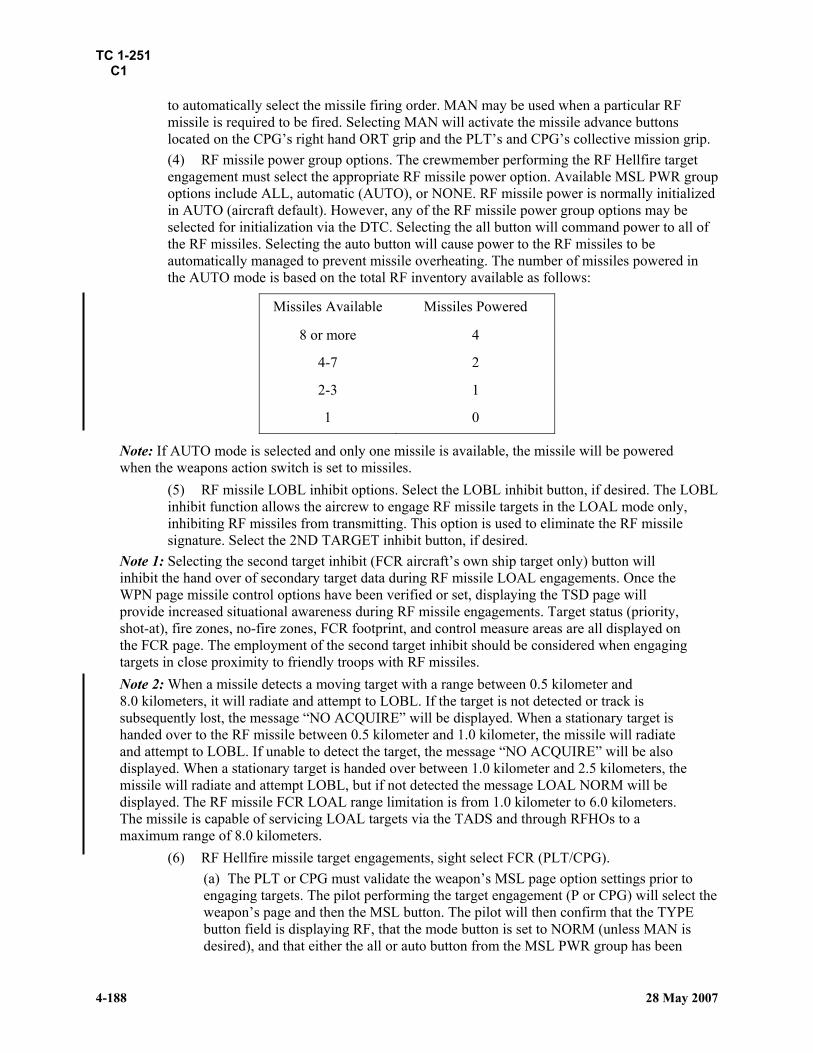
TC 1-251 C1
4-188 28 May 2007
to automatically select the missile firing order. MAN may be used when a particular RF missile is required to be fired. Selecting MAN will activate the missile advance buttons located on the CPG’s right hand ORT grip and the PLT’s and CPG’s collective mission grip. (4) RF missile power group options. The crewmember performing the RF Hellfire target engagement must select the appropriate RF missile power option. Available MSL PWR group options include ALL, automatic (AUTO), or NONE. RF missile power is normally initialized in AUTO (aircraft default). However, any of the RF missile power group options may be selected for initialization via the DTC. Selecting the all button will command power to all of the RF missiles. Selecting the auto button will cause power to the RF missiles to be automatically managed to prevent missile overheating. The number of missiles powered in the AUTO mode is based on the total RF inventory available as follows:
Missiles Available Missiles Powered
8 or more 4
4-7 2
2-3 1
1 0
Note: If AUTO mode is selected and only one missile is available, the missile will be powered when the weapons action switch is set to missiles.
(5) RF missile LOBL inhibit options. Select the LOBL inhibit button, if desired. The LOBL inhibit function allows the aircrew to engage RF missile targets in the LOAL mode only, inhibiting RF missiles from transmitting. This option is used to eliminate the RF missile signature. Select the 2ND TARGET inhibit button, if desired.
Note 1: Selecting the second target inhibit (FCR aircraft’s own ship target only) button will inhibit the hand over of secondary target data during RF missile LOAL engagements. Once the WPN page missile control options have been verified or set, displaying the TSD page will provide increased situational awareness during RF missile engagements. Target status (priority, shot-at), fire zones, no-fire zones, FCR footprint, and control measure areas are all displayed on the FCR page. The employment of the second target inhibit should be considered when engaging targets in close proximity to friendly troops with RF missiles. Note 2: When a missile detects a moving target with a range between 0.5 kilometer and 8.0 kilometers, it will radiate and attempt to LOBL. If the target is not detected or track is subsequently lost, the message “NO ACQUIRE” will be displayed. When a stationary target is handed over to the RF missile between 0.5 kilometer and 1.0 kilometer, the missile will radiate and attempt to LOBL. If unable to detect the target, the message “NO ACQUIRE” will be also displayed. When a stationary target is handed over between 1.0 kilometer and 2.5 kilometers, the missile will radiate and attempt LOBL, but if not detected the message LOAL NORM will be displayed. The RF missile FCR LOAL range limitation is from 1.0 kilometer to 6.0 kilometers. The missile is capable of servicing LOAL targets via the TADS and through RFHOs to a maximum range of 8.0 kilometers.
(6) RF Hellfire missile target engagements, sight select FCR (PLT/CPG). (a) The PLT or CPG must validate the weapon’s MSL page option settings prior to engaging targets. The pilot performing the target engagement (P or CPG) will select the weapon’s page and then the MSL button. The pilot will then confirm that the TYPE button field is displaying RF, that the mode button is set to NORM (unless MAN is desired), and that either the all or auto button from the MSL PWR group has been

TC 1-251 C1
28 May 2007 4-189
enabled. The PLT/CPG may select the LOBL inhibit or 2nd target inhibit buttons if desired. Messages are additionally displayed in the weapon status field of the AND that correspond to messages displayed in the HAD for RF missile engagements. (b) The PLT or CPG will select the appropriate FCR mode (RMAP, GTM, or ATM), activate a scan, and accept or select a target from the FCR page. (c) With the MSL options validated, the pilot performing the target engagement will then press the A/S indicator pushbutton to arm and note the arm/safe status window on the weapon’s page, change to indicate the arm status, and note that the A/S pushbutton amber arm indicator is now displayed. (d) With the WPN system armed, the pilot performing the target engagement will action MSL. The arm/safe status window on both the PLT’s and CPG’s weapon’s page will now be displayed in a crosshatched format along the border to indicate arm status with a weapon actioned. The opposite crewmember will note the pertinent CMSL or PMSL message displayed in his weapon control status field HAD message. One of the following weapon status field HAD messages will be displayed in the MSL weapons action switched crew station on the FCR page, HDU, or ORT HOD/HDD—
• NO ACQUIRE—RF missile has completed its attempts to acquire the target and has returned to the standby mode (LOAL).
• RF MSL TRK—RF missile is tracking (LOBL). • LOBL INHIBIT—RF missile trajectory is defaulted to LOAL, as the LOBL
inhibit mode has been selected (LOAL). • LOAL NORM—RF missile trajectory is defaulted to LOAL and RF missile
mode is set to NORM (LOAL). • LOAL MAN—RF missile trajectory is defaulted to LOAL and RF missile
mode is set to MAN (LOAL). Either LOBL or LOAL missile constraints symbology, as appropriate, will be displayed on the ORT HOD/HDD, FCR page, and HMD. The NTS target symbol border will change from dashed to solid.
Note 1: The RF missile should only be weapons action switched before or after an FCR scan, not during a scan. This practice permits the FCR to determine the target prioritization from complete scan burst data. The missile will be provided with data for NTS and ANTS targets based on the prioritization of the total target count. If the missile system is weapons action switched during the initiation of a scan, the FCR will hand over the first target detected. Note 2: If a brief period of time has elapsed, consideration should be given to performing a new FCR target acquisition scan to preclude using stale target data. Note 3: RF missile secondary target handover data is restricted to reflect the primary target’s characteristic as a STI. Note 4: Constraints symbology is referenced to the FCR NTS target. Note 5: The highest percentage of kill (Pk) shot is LOBL. Note 6: Shooting a stale STI greatly reduces the probability of detection for the RF missile.
(e) With the weapons system armed and missiles weapons action switched, the P* will then align the aircraft to achieve missile pre-launch constraints. Once satisfied that all pre-launch requirements have been met, the pilot performing the target engagement may then press the weapons trigger. Following the weapons trigger pull, a MSL launch message will be displayed for 2 seconds in the weapon status section of the weapons action switched crewmember’s HAD. HF TOF = NN will replace the launch message

TC 1-251 C1
4-190 28 May 2007
and will be displayed until predicted missile impact. When more than one missile is launched, the initial TOF is that of the first missile until impact followed, in turn, with the remaining TOF for each subsequently launched missile until their respective impact.
Note 1: Either a misfire or hangfire weapons status field message will display anytime that the WP does not detect a missile launch after a trigger pull is made, assuming all launch parameters are otherwise met. Note 2 (AH-64D with radar): When multiple FCR targets are displayed on the FCR and TSD page, the alternate NTS target will become the NTS target. If additional RF missiles are available, HAD messages and constraints symbology will be referenced to the new NTS target. Note 3: The TSD page will provide increased situational awareness during RF missile engagements. Target status (priority, shot-at), fire zones, no-fire zones, FCR footprint, and control measure areas are displayed. Note 4: Both rockets and missiles can be actioned by the crew at the same time. The weapons processor controls each wing store pylon independently of the other pylons. When either a rocket or missile system launch is in progress, all wing stores pylon weapons are inhibited from firing during the launch and for 2 seconds after. An “ALT launch” weapon control status field HAD message will be displayed to both crewmembers when a crewmember attempts to fire wing store weapons during a launch and for 2 seconds after.
(f) To de-action the missile system, select the weapons action switch on the ORT left handgrip (CPG) or cyclic (CPG/PLT) to MSL and observe that the weapon’s MSL page cross-hatch border on the arm/safe status window on the blanks and note that all missile HAD/MSL page messages and HAD symbology have blanked. The opposite crewmember will note that either the PMSL or CMSL weapon control status field message has blanked and that the LOBL/LOAL constraints box is no longer displayed.
(7) RF Hellfire missile target engagements, sight select TADS (CPG). (a) The CPG must validate the weapon’s MSL page option settings in accordance with paragraph 4 of this task and sight select TADS on the ORT RHG prior to engaging targets. The CPG will observe the weapon’s page sight status display showing “sight TADS” and the HAD sight select status field message displaying TADS. The CPG should then select the MSL button and observe the missile inventory icons change from normal to inverse video. The CPG should then ensure that the type is set to RF, that the mode is set to NORM (unless MAN is desired), and that MSL PWR is set to AUTO unless ALL is desired.
Note 1: Secondary target information is not applicable to TADS handover RF missile engagements. Note 2: Use of IAT/LMC will ensure proper target rates when tracking moving targets. Note 3: The CPG must place the NVS mode switch on the NVS mode control panel to OFF before the TADS will activate as a sight. This action will not turn the TADS FLIR sensor off. Note 4: Failure to perform an internal or out-front boresight prior to a TADS to RF missile hand over could result in an erroneous location being transmitted to the missile and a subsequent missile miss. This is more likely to occur when firing LOAL than in the LOBL mode and may be displayed as a broken LOAL box changing to a broken LOBL box despite designating a stationary target.
(b) With the MSL options validated, the CPG should then press the SAFE/ARM pushbutton indicator to arm. The arm/safe status window on the weapon’s page will

TC 1-251 C1
28 May 2007 4-191
change to indicate arm status. The SAFE/ARM pushbutton arm indicator will illuminate on the armament control panel. (c) With the weapons system armed, set the weapons action switch on the ORT left handgrip to MSL. The arm/safe status window on the weapon’s page will now be displayed in a cross-hatched format along the border to indicate ARM status with a weapon actioned. A “Target Data?” message will be displayed in the sight status field of the HAD. A Hellfire missile LOAL out of constraints box symbol will be displayed on flight and weapons symbology formats. The PLT will note the CMSL message displayed in his weapon control status field HAD message. (d) With the weapon’s system armed and missiles weapons action switched, the CPG should now select and operate the MAN TRK controller on the ORT right handgrip to track the target with a centered LOS and engage the IAT or LMC when desired. (e) To accomplish the TADS RF missile handover, the CPG must press the laser trigger to the second detent and hold until target data handover is complete (approximately 3 seconds). The “Target Data?” message displayed in the sight status field of the HAD will blank once TADS target data handover is complete. After TADS target data has been accepted by the RF missile, one of the following messages will be displayed in the weapon status field of the HAD (and Hellfire missile constraints box symbol)—
• NO ACQUIRE—RF missile has completed its attempts to acquire the target and has returned to the standby mode (LOAL).
• RF MSL TRK—RF missile is tracking (LOBL). • LOBL INHIBIT—RF missile trajectory is defaulted to LOAL, as the LOBL
inhibit mode has been selected (LOAL). • LOAL NORM—RF missile trajectory is defaulted to LOAL and RF missile
mode is set to NORM (LOAL). • LOAL MAN—RF missile trajectory is defaulted to LOAL and RF missile
mode is set to MAN (LOAL). Either LOBL or LOAL missile constraints symbology, as appropriate, will be displayed on the ORT HOD/HDD, FCR page, and HMD.
Note: An AH-64D without radar will commonly display the “Target Data?” message in the HAD sight status field. Whenever type is selected as RF, this message will always be present unless an RFHO has been received or a TADS RF handover has been accomplished.
(f) With the weapons system armed and missiles weapons action switched, the P* will then align the aircraft to achieve missile pre-launch constraints. Once satisfied that all pre-launch requirements have been met, the CPG may then press the weapons trigger on the ORT left handgrip. Following the weapons trigger pull, a MSL launch message will be displayed for 2 seconds in the weapon status section of the weapons action switched crewmember’s HAD. HF TOF = NN will replace the launch message and will be displayed until predicted missile impact. When more than one missile is launched, the initial TOF is that of the first missile until impact, followed in turn with the remaining TOF for each subsequently launched missile until their respective impact.
Note 1: Sight will replace the launch message in the weapons status field immediately following an RF missile launch from an AH-64D without radar. To blank the message and enable the TOF countdown, select another sight, for example, TADS. Note 2: Once the target data is replaced with the correct message for missile launch, the crew must ensure that missile launch is performed as soon as possible to increase probability of hit.

TC 1-251 C1
4-192 28 May 2007
Note 3: The WP gives PLT-activated missiles priority over the CPG. Note 4: If using a TADS to RF missile hand over to engage a target, the crew must be aware of the potential problems with laser ranging. If the laser range is erratic or questionable due to environmental conditions or poor technique, the data transferred to the RF missile may be corrupted or may make the RF missile believe a stationary target is moving. Note 5: To decrease the effect of target velocities building up over time, the crew should attempt to fire the LOAL TADS to RF missile hand over no longer than 5 to 7 seconds after the “Target Data ?” message disappears.
(8) RFHOs and engaging TSD NTS target with an RF Hellfire missile. Either the PLT or CPG, in an AH-64D with radar, may transmit an RFHO whenever it is desired to rapidly transmit FCR NTS target information to a primary member. The receipt capability of an RFHO is common to both the AH-64D with radar and the AH-64D without radar, and either the PLT or CPG may accept the RFHO and subsequently engage the presented RFHO target. RFHOs may be engaged with any onboard weapon system.
(a) Receiving RFHOs. See Task 1414 for a description of RFHO receiving procedures. (b) Engaging an RFHO target with RF missiles.
• After the RFHO has been properly received, the PLT or CPG (regardless of whether the aircraft is FCR equipped or not equipped) must sight select the FCR to transfer target data to an RF missile.
• Upon selecting the FCR sight, that crewmember will be provided with a radar range from the receiving own ship to that of the RFHO target. The range will be displayed on both the HAD of the FCR page and the HAD of the HDU or ORT (center MPD) of the receiving crewmember. AH-64Ds, both with and without radar, will additionally be provided with a “RF handover” status window centered on the receiver’s FCR pages. The TSD page will display the RFHO target overlaid with the NTS symbol. The aircrew will evaluate the displayed radar range to the target before launching the missile to ensure that a missile range probability of hit limitation is not violated.
Note 1: It is imperative that an RFHO be engaged immediately due to target latency. Note 2: The “RF handover” status window alerts the crew that the TSD NTS target is representative of the RFHO target. Note 3: Whenever a FCR TGT report is accepted (received), an “IDM target data” status window will be displayed on the receiving aircraft’s FCR page. This message alerts the crew that all the displayed TSD targets are now the FCR TGT Report targets. Note 4: An excessive range readout for an RFHO target will not provide an inhibit for missile firing. Note 5: The only time out associated with the remote hand over is the receiving ship must accept the RFHO within 6 minutes of the RFHO target data being received in the aircraft’s IDM buffer. After 6 minutes, the weapon inhibit “DATA INVALID” will be present and will prevent the crew from accepting the RFHO. Note 6: The target stale times do not continue counting up during an RFHO. RFHO target status does not reflect the true state of the target during an engagement and only reflects that target state at the time it was digitally sent from the transmitting aircraft.
• The PLT or CPG can now engage the NTS target.

TC 1-251 C1
28 May 2007 4-193
Note7: Sight will replace the launch message in the weapons status field immediately following an RF missile launch from an AH-64D without radar. To blank the message and enable the TOF countdown, select another sight (for example, TADS).
TRAINING AND EVALUATION REQUIREMENTS: 1. Training. Training may be conducted in the AH-64D aircraft or AH-64D simulator. The PLT/CPG should enable the weapon page train mode to enhance weapon system training. 2. Evaluation. Evaluation will be conducted in the AH-64D aircraft or AH-64D simulator. Evaluation may be conducted using train mode. Tactical evaluation support system (TESS) may be used to evaluate weapon system proficiency. Note: Live fire is not required for training and evaluation of this task.
REFERENCES: Appropriate common references.

TC 1-251 C1
4-194 28 May 2007
TASK 1462 Engage target with rockets
CONDITIONS: This task includes the following three conditions: 1. In an AH-64D helicopter with the weapon train mode enabled, target acquisition and designation sight (TADS) internal and outfront boresight completed, and weapons systems initialization completed, and if installed, fire control radar (FCR) operational checks completed and the pilot on the controls (P*) fitted with a boresighted helmet display unit (HDU). 2. In an AH-64D helicopter on a gunnery range with live rockets loaded, TADS internal and outfront boresight completed, weapons systems initialization completed, and, if installed, FCR operational checks completed and the P* fitted with a boresighted HDU. 3. In an AH-64D simulator with TADS internal and outfront boresight completed, weapons systems initialization completed, and if installed, FCR operational checks completed and the P* fitted with a boresighted HDU.
Note: Satisfactorily completing any one of the above conditions will satisfy the minimum requirement for the standardization evaluation. Completing any one of the three conditions will satisfy the gunnery tables III and IV requirement for readiness level (RL) 2 progression and an aviator’s task iteration requirement. A task iteration worksheet listing all three conditions separately is not necessary.
STANDARDS: Appropriate common standards and the following: 1. Place the system into operation. 2. Engage the target with pilot (PLT) (backseat crewmember) or copilot-gunner (CPG) (front seat crewmember) independent mode of aerial rocket system (ARS) firing. 3. Engage the target with cooperative mode of ARS firing.
DESCRIPTION: 1. Crew actions.
a. The P* will announce whenever he intends to unmask, remask, climb for diving fire, accelerate/decelerate for running fire, or reposition the aircraft and will maneuver the aircraft into constraints. b. The pilot not on the controls (P) will assist in monitoring the aircraft’s position while the P* maneuvers the aircraft into coincidence with the rocket steering cursor constraints and will provide adequate warning for obstacle avoidance. c. The crew will predetermine who will fire the rockets during a cooperative rocket mode target engagement. The crewmember that is to conduct the target engagement will announce his intention to conduct an independent or cooperative rocket engagement. He will announce the type and quantity of rockets to be fired, when ready to engage, and when the engagement is completed. The opposite crewmember will acknowledge all announcements and will confirm the actions of the first crewmember through the high action display (HAD) or one multipurpose display (MPD) displaying the opposite crewmember’s video select (VSEL) video display option.
Note: Selection and display of the opposite crewmember’s video and sight improves crew coordination and increases situational awareness during the execution of this task.

TC 1-251 C1
28 May 2007 4-213
Note: The allowable registration error is 1 foot in AZ/EL at 90 feet. The open center position of the LOS reticle is equivalent to 1 foot at 90 feet. When there is no other acceptable registration reference object, an individual may be positioned in front of the aircraft within the superimposed head tracker. The individual will require a light visible to both the PLT and CPG. The individual may hold the light at approximately the center of the torso. This allows the PLT and CPG to determine the quality of real world and image alignment. By viewing the light, the aviator is able to determine the registration point in a darkened environment.
e. Unity magnification check. Check the unity magnification of the FLIR image and reference object for a 1 to 1 relationship. The NVS TADS FLIR image will appear to be slightly larger than the real world viewed image due to its inherent 1.2 magnification versus the PNVS's 1.1 magnification. f. Infinity focus check. The FLIR’s infinity focus is checked by placing the LOS on the horizon, relaxing the eye, and concentrating on the thermal image, and changing symbology modes. Considering that a gray scale infinity focus was previously accomplished, the symbology should remain in focus. If the symbology is not in focus, use the procedures described in Task 1135. If the FLIR image is not focused out to infinity, contact maintenance personnel and make any appropriate DA Form 2408-13-1 (Aircraft Status Information Record) comments.
Note: Initial infinity focus of symbology is accomplished during gray scale checks. g. Alternate NVS sensor check. The PLT or CPG will announce when he takes control of the alternate sensor and when he completes the check. Set the NVS select switch, on the collective flight grip, to TADS or PNVS as desired. Check selected sensor’s turret movement coincident with real world image. Set the NVS select switch, on the collective flight grip, to the primary sensor or as desired.
TRAINING AND EVALUATION REQUIREMENTS: 1. Training may be conducted in the AH-64D aircraft or AH-64D simulator. 2. Evaluation will be conducted in the AH-64D aircraft or AH-64D simulator.
REFERENCES: Appropriate common references.

TC 1-251 C1
4-214 28 May 2007
TASK 2010 PERFORM MULTIAIRCRAFT OPERATIONS
CONDITIONS: In an AH-64D helicopter and given a unit standing operating procedure (SOP).
STANDARDS: Appropriate common standards and the following: 1. Participate in a formation flight briefing according to the unit SOP. 2. Perform formation flight as briefed. 3. React to loss of visual contact according to the unit SOP.
DESCRIPTION: 1. Crew actions.
a. The pilot on the controls (P*) will focus primarily outside the aircraft, keeping track of other aircraft on the route of flight. He will announce any maneuver or movement before execution and inform the pilot not on the controls (P) if visual contact is lost with other aircraft. If visual contact is lost with other aircraft, the crew will immediately notify the flight and begin reorientation procedures. If instrument meteorological conditions (IMC) are encountered, execute inadvertent instrument meteorological conditions (IIMC) break up as briefed. b. The P will provide adequate warning of traffic or obstacles detected in the flight path and identified on the map. He will assist in maintaining aircraft separation. He will inform the P* if visual contact is lost with other aircraft, and if threat elements are detected or sighted. He will perform duties as briefed. He will notify the P* when his attention is focused inside the aircraft. c. The P should frequently assist the P* by communicating his situational awareness perceptions and formation/multiship observations. Additionally, the P should assist the P* by monitoring aircraft systems, by operating the navigation system, and by scanning the air route for possible enemy activity or other hazards and obstacles that could impact the integrity and security of the flight. d. If visual contact with the other aircraft is not reestablished (<5 seconds), then the crew will notify the flight by transmitting their call sign and the proword “BLIND” (for example, “Gun 2 is BLIND”). The flight will then begin reorientation procedures. e. When an aircraft in the flight calls ‘BLIND,” the flight must remain predictable and provide cueing to the BLIND aircraft by transmitting the flights location in reference to an easily/rapidly identifiable manmade, natural, or electronic feature (for example, “Gun 2 is BLIND” -- “Roger, Lead is north of the bridge heading 360 degrees at hard deck altitude maintaining 100 knots true, coming up position lights bright”). f. If instrument meteorological conditions (IMC) are encountered, execute IIMC breakup as briefed.
Note: The most important consideration when an aircraft has lost visual contact with the flight is to immediately notify the flight and execute reorientation procedures. Except for enemy contact, all mission requirements are subordinate to this action.
2. Procedures. Maneuver into the flight formation, changing position as required. Maintain horizontal and vertical separation for the type of formation being flown. If the tactical situation requires, perform techniques of movement as briefed.
a. Takeoff: All helicopters should leave the ground simultaneously. The trailing aircraft must remain at a level altitude or stack up 1 to 10 foot vertically to remain out of the disturbed air of the aircraft in front of them. In the event an aircraft in the flight loses visual contact with the

TC 1-251 C1
28 May 2007 4-215
formation, it will immediately make a radio call to the formation and the P* will initiate a climb above the briefed cruise altitude and attempt reorientation of the formation. b. Cruise: Free cruise formation should be employed when operating at terrain flight altitudes or in a combat environment. This will allow the individual aircraft more flexibility to move within the formation to avoid terrain, obstacles, and enemy threat. During periods of degraded visibility, crews are more susceptible to losing other aircraft in the formation. Crews should consider flying a close formation to maintain orientation on the flight. In the event an aircraft in the flight looses visual contact with others in the flight, it will immediately make a radio call to the lead. The lead will announce the heading, altitude, and airspeed. The lead must maintain this heading, altitude, and airspeed until all aircraft have rejoined the flight. The aircraft that has lost visual contact with the flight will immediately assume the flights heading and airspeed and maintain vertical separation as briefed. The flight will begin reorientation procedures. The most important consideration when an aircraft has lost visual contact with the flight is reorientation. Except for enemy contact, all mission requirements are subordinate to this action. Unit SOPs must state the procedures for reestablishing contact with the flight. Considerations should include but are not limited torally to a known point, use covert/overt lighting, use the FCR (if equipped), and use ground rally. METT-TC, power available, and ambient light will influence how contact is reestablished. When a flight rallies to a known point, the point may be an ACP along the route, a PP sent by lead, or a terrain feature. Situations may occur when an aircraft rejoins the flight in a position other than briefed. Mission commanders may use altitude, a TRP/PFZ, a cardinal direction, or other method to maintain separation. Only after the entire flight is reformed can the mission commander proceed with the mission. c. Approach: The lead aircraft must maintain a constant approach angle so other aircraft in the formation will not have to execute excessively steep, shallow, or slow approaches. Aircraft should not descend below the aircraft ahead of them in the formation to avoid entering their rotor wash. This could result in an over torque, loss of aircraft control, or entering a settling with power condition. In the event an aircraft in the flight loses visual contact with the formation, it will immediately make a radio call to the formation and execute a go-around in the briefed direction.
Note1: The P* must keep the P thoroughly informed to what he is observing and doing throughout the formation flight or multiship operation. Normally, the pilot ([PLT] backseat crewmember) will be on the controls, using the pilot night vision system (PNVS). The copilot-gunner ([CPG] front seat crewmember) may be out of the NVS normal (NORM) position uing target acquisition and designation sight (TADS) or TADS acquisition-gunner helmet sight (ACQ-GHS) on occasions in the narrow and zoom fields of view (FOV) during the execution of his duties. The constricted perceptual limits of narrow and zoom FOVs necessitates the need for the P* to inform the CPG where they are at in time and space. This is especially important in the case of a pilot’s IHADSS failure that requires the CPG to take over aided flight duties. Keeping the CPG informed will reduce the negative effects of transitioning from a TADS narrow or zoom frame of mind to a wide field of view (WFOV) perspective of time and space. The P should frequently assist the P* by communicating his situational awareness perceptions and formation/multiship observations. Additionally, the pilot not on the controls should assist the P* by monitoring aircraft systems and scanning the air route for possible intruders or other hazards and obstacles to the integrity and security of the flight.
Note2: Regardless of the number of aircraft in the formation, the lead/wing concept must be applied. During multiaircraft operations, additional crew actions from Task 2043 (Perform team employment techniques) and Task 1412 (Perform evasive maneuvers) must be considered.
Note3: All multiaircraft operations will be briefed using a unit-approved multiaircraft/mission briefing checklist. The following are mandatory briefing items and must be included in all multiaircraft briefings.

TC 1-251 C1
4-216 28 May 2007
MultiAircraft Operations Briefing Checklist
1. Formation type(s) 2. Altitude 3. Airspeed 4. Aircraft lighting 5. Lead change procedures 6. Loss of visual contact/in-flight linkup 7. Loss of communications procedures 8. IIMC procedures 9. Actions on contact
10. Downed aircraft procedures
NIGHT OR NIGHT VISION DEVICE (NVD) CONSIDERATIONS: Increase the interval between aircraft to a minimum of three to five rotor disks. Keep changes in the formation to a minimum. All crewmembers must avoid fixation by using proper scanning techniques.
1. Night. During unaided night flight, the crew should use formation and position lights to aid in maintaining the aircraft's position in the formation. 2. NVD. The reduced infrared signature of the AH-64D makes multiship operations, in general, and pilot night vision system (PNVS) formation flights challenging tasks initially. The PNVS and NVS NORM TADS-forward-looking infrared (FLIR) presents a two-dimensional image that makes depth determination and rates of closure difficult to detect and measure. When conducting formation flight, the crew must learn to use FLIR cues to maintain visual reference and separation from other aircraft.
NIGHT VISION SYSTEM (NVS) NIGHT VISION GOGGLES (NVG) CONSIDERATIONS:
WARNING
During periods of reduced visibility, crewmembers may lose sight of other aircraft in the formation. If this occurs, the crewmember should announce loss of visual contact and transmit a call to the other aircraft in the formation.

TC 1-251 C1
28 May 2007 4-216.1
1. NVS. The multiship/formation procedures found in TC 1-204 generally apply to NVS operations. However, to exploit advantages and diminish limitations of the AH-64D’s PNVS and NVS-TADS FLIR, certain techniques and procedures should be modified. 2. FLIR optimization. Formation/multiship flight FLIR optimization normally requires dynamic adjustments to the gain and level settings as the flight transitions into and out of the various modes of flight. The night system (NS) crew will normally find it necessary to reoptimize their specific FLIR sensors each time a flight mode transition is made or as changing environmental conditions dictate. 3. NVS NORM operations with the TADS-FLIR will normally require more frequent reoptimization than that of the PNVS. 4. Polarity determination. Many environmental and sensor performance factors will affect the personal determination of which polarity is ideal for application at a specific given place and time. As FLIR images vary in quality and contrast, switching polarities can be a useful tool in maintaining visual contact with the other multiship operation aircraft. This is particularly important when experiencing adverse effects of alternating current (AC) coupling. 5. Performance distinctions between NVS-TADS and PNVS. The capabilities and limitations of the PNVS are fairly well known and documented. However, the pilot in command (PC) and the other PLT or CPG must also possess a basic understanding of performance distinctions that exist between the NVS NORM WFOV TADS-FLIR and the PNVS. 6. NVS multiship formations. In support of the tactical unit’s METL, the aircrew will develop those skills necessary to participate in NVS multiship formation flight. The unit SOP will likely incorporate some variations to the two most common NVS FLIR formations. The first formation, NVS staggered right, is a flight formation designed for deploying a formation of FLIR aircraft at no lower than low level terrain flight mode. The second common formation is NVS free cruise, which is designed for the tactical deployment of NVS aircraft in the NOE and contour terrain flight modes.
a. NVS echelon trail right. The aircrew will fly as part of the NVS staggered right formation when en route to a specific control point or destination at no less than low level flight altitudes. The formation is essentially a highbred trail formation flown with a 20-degree offset (echelon) that takes full advantage of the NVS’s 40-degree field of view. The formation requires a great deal of P* skill and attention. A 20-degree echelon allows for the safe egress of aircraft from the formation and also allows for safe position changes. The aircrew will be prebriefed as to what the required minimum horizontal (normally 3, 5, or 7) and vertical (as desired or SOP), rotor disk separation will be between aircraft. The aircrew will normally participate as part of a team or section. The unit SOP and -T will dictate any horizontal separation of participating teams or sections. Vertical separation will be flown per unit SOP and briefing. If either the PLT or CPG is the P* using the NVS NORM TADS-FLIR, a minimum step up of 5 to 10 feet will be required to maintain aircraft FLIR video intervisibility in turns (roll attitude) due to the negative AC coupling video effect. b. NVS free cruise. The NVS free cruise multiship formation provides participating aircrews with lateral flexibility and greater horizontal distance between aircraft. Combined with an effective scanning technique, NVS free cruise allows more time to scan the terrain and horizon for obstacles, threat, and other aircraft. It will allow flexibility of movement during nap of the earth (NOE) and contour flight. NVS free cruise allows movement up to 45 degrees either side of lead aircraft. During NVS flight, u only the right 45-degree sector simplifies chalk number and team identification. An independent team wingman may find it more effective to be allowed the freedom of maneuver of both 45-degree sectors. Horizontal separation will normally equal 8 to 12 rotor disks until reaching a designated control measure and, from that point, any further separation will be dictated by SOP and mission, enemy, terrain and weather, troops and support available, time available, civil considerations (METT-TC). Vertical separation of teams and sections will vary with terrain, obstacles, and the tactical situation.

TC 1-251 C1
4-216.2 28 May 2007
7. AC coupling effects in rolling (banking) flight. To reduce the adverse effects of AC coupling, reduce the amount of sky visible within the NVS NORM TADS-FLIR (the ALFGL circuited PNVS is not normally affected) field of view. To reduce the visible horizon in a turn or rolling maneuver, depress the NVS sensor just enough to view more of the terrain below the horizon. As part of a formation flight performing a turn (change of heading), a trailing aircraft must reduce the visible horizon by viewing the preceding aircraft from a higher vertical separation aspect, normally 10 feet. This preventative NVS NORM TADS-FLIR technique helps to assure that the limit emitting diodes (LEDs) are operating within their operational limitations by decreasing the drastic signal changes from the infrared (IR) detectors. 8. Night vision goggles (NVG). When conducting NVG formation flight, the crew should use the IR position lights and/or IR strobe lights to maintain aircraft position in the formation (METT-TC dependent). 9. When one crewmember is using NVGs during formation flight, the opposite crewmember should acquisition select the opposite crewmember’s HMD. 10. When using NVGs during formation flight in an urban environment, altitude should stack down to “sky light” the aircraft ahead and prevent loss of visual reference in the city lights (METT-TC dependent). Note1: If visual contact is lost with the aircraft ahead of you, using the FCR in the ATM mode will help facilitate a linkup if your aircraft is FCR equipped. Note2: White-hot polarity provides the best resolution and reference during NVS formations.
TRAINING AND EVALUATION REQUIREMENTS: 1. Training will be conducted in the AH-64D aircraft. 2. Evaluation will be conducted in the AH-64D aircraft.
REFERENCES: Appropriate common references.

TC 1-251 C1
28 May 2007 4-221
d. L-pattern. The L attack pattern (figure 4-7) is most effective against targets requiring a large volume of fire for a short duration. Teams in the L-pattern are capable of attacking linear targets or targets that are masked on one side by natural or man-made obstacles. L-pattern is best suited for two teams attacking sequentially.
Figure 4-7. L–pattern.
NIGHT/NIGHT VISION DEVICE (NVD) CONSIDERATIONS: Under NVD, the crew must maintain situational awareness and spacing between team members. Crew and team coordination becomes imperative. Due to the slow slew rates of the target acquisition and designation sight (TADS), wearing night vision goggles (NVGs) in the front seat could greatly enhance the copilot-gunner’s (CPG) (front seat crewmember) effectiveness. The crew must exercise care when observing the impact of rounds because the flash signature may momentarily degrade the capability of the NVG. When firing rockets, missiles, adjusting indirect fire, or firing the 30-millimeter chain gun off axis, the crew must follow procedures to protect their night vision.
TRAINING AND EVALUATION REQUIREMENTS: 1. Initial training may be conducted in the AH-64D aircraft or AH-64D simulator. 2. Evaluations will be conducted in the AH-64D aircraft.
Note: Crewmembers will ensure that the appropriate authority has authorized any training flights.
REFERENCES: Appropriate common references.

TC 1-251 C1
4-222 28 May 2007
TASK 2045 OPERATE THE IR ZOOM LASER ILLUMINATOR-DESIGNATOR (IZLID) 1000P-W LASER
CONDITIONS: In an AH-64D helicopter with an IZLID 1000P-W laser installed, target acquisition designation sight (TADS) internal and outfront boresight completed (not required with modernized target acquisition designation sight [MTADS]), weapons systems initialization completed, and the pilot using the IZLID (either P* or P) wearing AN/ANVIS-6 night vision goggles.
STANDARDS: Appropriate common standards and the following: 1. Place the system into operation. 2. Conduct IZLID boresight. 3. Employ the IZLID laser for target designation and pointing. 4. Use appropriate night brevity codes according to FM 3-09.32.
DESCRIPTION: 1. Crew actions.
a. The P* will announce when he intends to unmask, remask, or reposition the aircraft and will maneuver the aircraft into position. b. The pilot not on the controls (P) will assist in monitoring the aircraft’s position while the P* maneuvers the aircraft and will provide adequate warning for obstacle avoidance. c. The crewmember will announce when intending to perform target designation and pointing, when operating the IZLID, and when completing the operation. The opposite crewmember will acknowledge all announcements and will confirm the actions of the crewmember performing IZLID laser operations through one multipurpose display (MPD) displaying the opposite crewmember’s video select (VSEL) video display option or looking outside the aircraft to physically locate the laser spot.
Note: Selection and display of the opposite crewmember’s line-of-sight (LOS) reticle improves crew coordination and increases situational awareness during the execution of this task. 2. Procedures.
a. Gun page common settings. (Page setup for using the IZLID 1000P-W laser is similar to Task 1464.)
(1) Select the gun maintained option button. The gun icon will change to inverse video and the gun control option buttons will be displayed. (2) Set the independent gun mode to normal (NORM). The gun mode is initialized by the aircraft default in the NORM mode unless set to FXD on the data transfer cartridge (DTC).
b. IZLID boresighting procedure. Boresight procedure will be IAW current IZLID Laser AWR.

TC 1-251 C1
28 May 2007 4-223
WARNING
The IZLID 1000P-W is a Class IV invisible non-eye-safe laser. All personnel should be alerted to the hazards specific to the IZLID. Avoid direct exposure to the beam to prevent eye injury. The laser is not disabled with the master arm switch, therefore it can be operated with the aircraft weight on wheels. To prevent eye injury, ground personnel should wear eye protection with a minimum optical density of 3.0 at wavelengths of 860 nanometers. Minimum safe skin distance is 43 meters. Use with the precautions of any direct fire weapon.
Note1: During operations with the IZLID laser, and night vision goggles (NVG) are not being worn, a laser-visor or spectacles must be worn for eye protection. When NVG are being worn, CLEPIR spectacles must also be worn for eye protection. Using laser eye protection (spectacles) with NVG may degrade the NVG’s transmissivity.
Note2: Flight testing revealed that the IZLID laser boresight relative to the gun is not maintained during Area Weapons System (AWS) engagements. c. Normal laser operations. The gun mode that may be employed with the IZLID 1000P-W is NORM. The normal mode allows the gun to flex in azimuth and elevation as directed by the weapons processor (WP) for effective laser pointing and target designation while using the P* or P’s HMD or TADS as the selected LOS.
(1) After the WPN’s gun page options have been set or verified, the pilot or CPG desiring to use the IZLID 1000P-W will action the gun and sight select (SEL) HMD on his collective mission grip’s sight SEL switch. The CPG will turn the IZLID power rotary switch to the LOW, HIGH, or PULSE position. The pilot or CPG will insert a manual range of 1,000 meters on the weapons page. The CPG may sight select TADS on his ORT right handgrip instead of HMD. (2) Depending on environmental conditions, the P* or P may see the entire beam or just the flickering of the infrared (IR) pointer on the ground. Used alone or in conjunction with other IR marking devices, IR pointers are very effective for identifying both friendly and enemy positions. The P* or P may point the beam of the laser directly at the target, “rope” the target or friendly location, or use other methods to designate the target. (Other marking procedures can be found in JP 3-09.3.) (3) Any IR pointer will be seriously degraded by high light levels, high humidity, or battlefield obscurants. The low grazing angle inherent with ground or low flying aircraft will result in under spill (appears as multiple spots between the source and the target) or over spill (appears as spots beyond the target).
Note1: The purpose of the IZLID 1000P-W is to provide the crew the capability to confirm target location with ground forces and thereby minimize the potential for fratricide. IZLID laser should be limited to target illumination/pointing and not be used as a means of directing AWS fire. Note2: Energy from the IZLID laser may be reflected back to the crew during use. The minimum safe employment range is 620 meters. Recommend an employment range of greater than 620 meters be maintained to minimize the risk to the crew and ground personnel. The IZLID laser should only be powered when the AWS is the weapon actioned and a target is being designated. Direct view optics (DVO) will increase the minimum safe range.

TC 1-251 C1
4-224 28 May 2007
Note3: To designate targets with the IZLID laser beyond 1,000 meters, a manual range of 1,000 meters must be entered into the WP to prevent the gun barrel from elevating above LOS. Note4: Proper crew coordination must occur between the ilot and for activating and deactivating the IZLID 1000P-W laser, as the IZLID power rotary switch is only located in the CPG’s cockpit.
TRAINING AND EVALUATION REQUIREMENTS: 1. Training may be conducted in the AH-64D aircraft. 2. Evaluation will be conducted in the AH-64D aircraft.
REFERENCES: Appropriate common references plus the following:
AWR 2004D-A51 JP 3-09.3 JP 3-09.32 Task 1138 and Task 1464

TC 1-251 C1
28 May 2007 4-225
TASK 2050 Develop an emergency global positioning system (GPS) recovery procedure
WARNING
This procedure is strictly for recovery under visual meteorological conditions (VMC) for training and for inadvertent instrument meteorological conditions (IIMC) use only and will not be used for a planned IFR flight unless approved by USAASA. This emergency recovery procedure is only authorized to be flown when the situation prevents the use of an approved navigational aid.
Note: This task should be selected for instrument examiners.
CONDITIONS: With a tactical or aeronautical map with current obstruction information. A mission planning system with digital maps and recent CHUM may be used to aid in developing this procedure. STANDARDS:
1. Select a suitable recovery/landing area and coordinate, if required, airspace deconfliction. 2. Select an approach course (degrees magnetic), a missed approach course, final approach
fix (FAF), missed approach point (MAP), intermediate approach fix (IF), initial approach fix (IAF) and missed approach holding fix (MAHF).
3. Determine obstacle clearance for the final, MAHF, missed, intermediate, initial segments, and the MSA.
4. Determine altitudes based on obstacle clearance for FAF, MAHF, MAP, IF, IAP, and MSA.
5. Determine the appropriate obstacles in the missed approach segment and determine 20:1 slope penetration.
6. Establish a 3 nautical mile (NM) holding pattern at the MAHF. 7. Prepare an emergency recovery procedure diagram per the example. 8. Complete a suitability/flyability check—to include loading waypoints—under VMC to
validate the procedure.
Note 1: All altitudes are in eet MSL, all waypoints are LAT/LONG, all distances are NM, and visibility is SM. All obstacles are MSL unless otherwise noted. The FIH has the necessary conversion tables.
WARNING
Ensure coordinates for maps and GPS are the same datum (for example, WGS-84) or the point on the ground may be off significantly and obstacle clearance will be questionable.

TC 1-251 C1
4-226 28 May 2007
Note 2: PPS refers to the GPS precise positioning service. It is Department of Defense (DOD) policy that military aircraft operate with the GPS in the PPS mode.
Note 3: Complete the enclosed figures for determining approach criteria. The width cannot be adjusted.
DESCRIPTION: 1. Most suitable recovery/landing area. Select an area based on mission, enemy, terrain and weather, troops and support available, time available, civil considerations (METT-TC) and obstacles. Ensure proper coordination for airspace deconfliction has been done. 2. Final approach segment. The final approach segment begins at the FAF and ends at the
MAP. a. Determine the MAP (normally associated with the landing area or threshold). b. Determine the FAF. The minimum distance is 3 NM from the MAP. The maximum
length is 10 NM. The optimum length is 5 NM. The width is 2.4 NM (1.2NM on either side of the centerline).
3. The MAHF. Determine the MAHF for the landing area. The minimum distance is 3 NM and the maximum distance is 7.5 NM from the MAP. The optimum distance is 5 NM. The holding pattern leg will not exceed 3 NM. The width is 4 NM (2 NM on either side).
Solution: (A) _____ (rounded up nearest 100 ft) + (B) 1,000 ft = (C) _____ (MAHF altitude)
Note: (A) = Highest obstacle within 10 NM centered on the MAHF
Table 4-1: MAHF altitude calculation table
4. Missed approach segment. a. The missed approach segment will start at the MAP and will end at a holding point
designated by a MAHF. b. Optimum routing is straight ahead (within 15 degrees of the final approach course) to
a direct entry. A turning missed approach may be designated if needed for an operational advantage but is not discussed in this task due to the complexity of determining obstacle clearance.
c. The area of consideration for missed approach surface and the 20 to 1 obstacle clearance evaluation apply for all rotary wing.
5. Intermediate approach segment. The intermediate segment begins at the IF and ends at the FAF. Determine the IF. The minimum distance is 3 NM and the maximum distance is 5 NM from the IF to the FAF. The width is 4 NM (2 NM on either side).
6. Initial approach segment. The initial approach segment begins at the IAF and ends at the IF. Determine the IAF. Up to three IAFs are allowed. The minimum distance is 3 NM from the IF and the maximum distance is 10 NM. The width is 4 NM (2 NM on either side).
7. MSA for the landing area. To determine the MSA for the landing area, use the OROCA or ORTCA elevation from the en route low altitude (ELA) chart for the area of operations, if available. Select the highest altitude within 30 NM of the MAP.
a. If an ELA is not available, the minimum sector altitude will be determined by adding 1,000 feet to the maximum elevation figures (MEFs). When a MEF is not available, apply the 1,000-foot rule to the highest elevation within 30 NM of the MAP.

TC 1-251 C1
28 May 2007 4-227
b. Minimum sector altitudes can be established with sectors not less than 90 degrees° and with sector obstacle clearance having a 4 NM overlap. Use the following for determining MSA.
Solution: (A) _____ (rounded up nearest 100 ft) + (B) 1,000 ft = (C) _____ (MSA)
Note: (A) = Highest obstacle within 30 NM centered on the MAP
Table 4-1.1 MSA calculation table
8. The procedures diagram. The procedure diagram may be computer generated or hand sketched. The diagram need not be as detailed as a DOD-approved chart, but it must provide all data as outlined in the example to execute the procedure.
a. The plan view. The plan view will include the following: (1) The highest obstacle altitude (MSL) in BOLD. (2) The approach course (degrees magnetic), IAF, IF, FAF, MAP, MAHF holding
pattern, obstacles, and MSA. It also includes the following terms: • “FOR VFR TRAINING and EMERGENCY USE ONLY” twice. • “PPS REQUIRED.”
b. Minimums section. The minimums section will include the following. The minimum descent altitude, visibility, and the height above landing (HAL). Use Table 4-1.2 to compute the landing visibility minimum based on HAL.
c. Landing area sketch. The landing area sketch includes a drawing/diagram of the landing area and the elevation of the highest obstacle within the landing area (if applicable).
d. Prior to publication, the diagram will include, as a minimum, all items included in the following diagram.
250 – 475 ft 476 – 712 ft 713 – 950 ft
Landing visibility minimum (SM) ½ ¾ 1.0
9. Flight check. Complete a flight check under VMC in an aircraft to finalize the procedure and validate the diagram. Once a successful flyability/suitability check has been completed, the diagram will be validated by the developer in the lower marginal data area. Once validated by the developer, the procedure must be approved by the appropriate authority in the lower marginal data area prior to publication. The flight should validate the following:
a. Locations—IAF, IF, FAF, MAP, and MAHF. b. Obstacles. c. Approach course. d. Obstacle clearance. e. Altitudes—MDA, FAF, IF, IAF, MSA/holding pattern altitude.
Note: All waypoints (IAF, IF, FAF, MAP, and MAHF) will be verified by two separate GPS NAV systems, for example, DGNS, EGI, PLGR. At least one will have PPS. If unable to complete a suitability/flyability check due to the operational environment, the commander should consider an elevated risk when using this recovery procedure.

TC 1-251 C1
4-228 28 May 2007
TRAINING AND EVALUATION REQUIREMENTS:
1. Training may be conducted academically.
2. Evaluation may be conducted academically.
REFERENCES: Appropriate common references plus the following: FAA Handbook 8260.3 (TERPS Manual) FAA Order 8460.42A (Helicopter GPS Nonprecision Approach Criteria) FAA Order 7130.3 (Holding)

TC 1-251 C1
28 May 2007 4-228.1
Figure 4-8. Final approach fix altitude
Figure 4-8(a). Initial approach fix

TC 1-251 C1
4-228.2 28 May 2007
Figure 4-8(b) Minimum Descent Altitude (MDA)
Figure 4-8(c). Missed approach obstacle clearance

TC 1-251 C1
28 May 2007 4-228.3
Figure 4-8(d). Sample GPS approach

This page intentionally left blank.

TC 1-251 C1
28 May 2007 4-243
TRAINING AND EVALUATION REQUIREMENTS: 1. Training and evaluation will be conducted in the AH-64D aircraft, at night, with a NVG IP/SP. 2. Training and evaluation will be conducted in the AH-64D aircraft, at night, with a NVG IP/SP.
REFERENCES: Appropriate common references

TC 1-251 C1
4-244 28 May 2007
TASK 2127 PERFORM COMBAT MANEUVERING FLIGHT
CONDITIONS: In an AH-64D in an approved training area or simulated tactical environment, with a properly fitted helmet display unit (HDU), and aircraft cleared.
STANDARDS: Appropriate common standards and the following:
1 Perform low altitude warning recovery if aircraft is allowed to descend below predetermined recovery altitude.
CAUTION Do not exceed gravity force (G) limits versus gross weight (GWT) and airspeed limitations outlined in TM 1-1520-251-10, chapter 5 and AWR 2006D-A02.
Note: To avoid undesired control input (for example, force trim overshoot while maneuvering) either maintain the force trim interrupted throughout the maneuver, or leave force trim engaged until maneuver is completed.
DESCRIPTION: 1. Crew actions.
a. The pilot in command (PC) will consider and ensure the crew is aware of the effects of an engine failure during combat maneuvering flight. Airspeed should be maintained between minimum and maximum single engine airspeed. If an engine failure occurs above or below these airspeeds, torque will immediately double, associated with possible target (TGT) limiting, which will result in rapid rotor decay that may not be recoverable. b. The pilot on the controls (P*) will remain primarily focused outside the aircraft throughout the maneuvers. The P* will set the low altitude warning on the radar altimeter to the desired recovery altitude. The P* will make smooth and controlled inputs. Desired pitch and roll angles are best determined by referencing aircraft attitude with the outside horizon and/or helmet display unit (HDU) symbology. The P* will only momentarily divert focus during critical portions of the maneuver to ensure trim, torque, and rotor control are maintained. He will announce the maneuver to be performed and any deviation from the maneuver. He also will announce recovery from the maneuver. c. The P will provide adequate warning to avoid enemy, obstacles, or traffic detected in the flight path and any deviation from the parameters of the maneuver. He will also announce when his attention is focused inside the cockpit (for example, when monitoring airspeed, altitude, attitude, or rotor revolutions per minute [RPM]). d. Low altitude warning recovery. Should at any time the low altitude warning audio sound, the aircrew shall give their sole attention to placing the aircraft back above the minimum altitude. The P* will ensure that the nose of the aircraft is placed equal to or above the horizon prior to adding power to preclude accelerating, descending flight. Tactical play, radio transmissions, and nonessential intercommunication system (ICS) shall cease until the P* states “BACK ABOVE” to the P.
2. Procedures. a. Decelerating turn. The decelerating turn is used to rapidly change the direction of the aircraft at low-level altitudes while trading energy to maintain safe operational altitude.

TC 1-251 C1
28 May 2007 4-245
The angle of bank, airspeed, gross weight, and environmental conditions at the initiation of the maneuver will determine the amount of deceleration necessary to maintain altitude.
(1) During flight with lower forward airspeed, typically below maximum rate of climb airspeed, the deceleration will require an increase of collective, resulting in an increase in torque. While at airspeeds greater than maximum rate of climb, the airspeed may be traded off while adjusting collective to maintain torque within limits and maintain altitude. (2) Apply directional cyclic to initiate turn. As aircraft begins to move about the roll axis, apply aft cyclic as necessary to maintain altitude by trading airspeed. Apply pedal as necessary to maintain aircraft in trim. Adjust collective as necessary to maintain altitude and rotor within limits. To recover, apply opposite and forward cyclic while adjusting collective to maintain torque within limits as the rotor system unloads.
CAUTION 1 Most transient over-torques occur as the aircraft unloads during maneuver recovery (for example, as coning dissipates with left cyclic applied).
CAUTION 2 Close attention must be paid to rotor RPM to prevent rotor over-speed. High GWT, high density altitude, and high G-loading aggravate this.
b. Break turn. The break turn is used at terrain and cruise flight altitudes to rapidly change the direction of the helicopter while maintaining or gaining airspeed. As altitude allows, this turn also enables a simultaneous three-axis change of position and direction. This maneuver is effective when performing evasive maneuver against small arms, radar directed air defense artillery (ADA), or to employ weapons. Its effectiveness is enhanced when used in conjunction with flares or chaff.
(1) At cruise altitudes, apply directional cyclic to initiate turn. As roll rate and angle increases, the nose will begin to fall. Allow this to occur while maintaining trim with pedals. Recovery is affected by applying opposite cyclic when reaching desired heading. Once the aircraft’s wings level in roll, apply collective and aft cyclic when reaching desired airspeed/altitude. (2) At terrain flight altitudes, initiate with aft cyclic to ensure adequate obstacle clearance, followed immediately by directional cyclic. Angles of bank are much lower than those utilized during cruise flight, as much less recovery altitude is available. Adjust collective as necessary to maintain altitude and compensate for transient torque. Maintain trim with pedals. Do not allow the nose to fall far below the horizon, as this is conducive to sink rate build up. Consider desired direction of turn before initiating and seek masking terrain if evading enemy fire. To recover, apply opposite and forward cyclic.

TC 1-251 C1
4-246 28 May 2007
CAUTION 1 Excessive bank angles at terrain flight altitudes may not allow sufficient recovery time. Airspeed (kinetic energy) may not be available to trade for lift and must be evaluated prior to and during the maneuver. This is aggravated as helicopter GWT and density altitude increase.
CAUTION 2 Do not allow high sink rates to develop, as recovery altitude may not be available. This is aggravated as helicopter GWT and density altitude increase.
CAUTION 3 Most transient over-torques occur when initiating break turns to the left or during recovery from a break turn to the right.
c. Cyclic climb to a pushover break. This maneuver is used in conjunction with complex terrain or close-range running fire engagements to rapidly reposition the aircraft when receiving small arms fire and reorient the aircraft weapons on the enemy. Initiate the maneuver from cruise airspeed. Apply aft cyclic to attain sufficient altitude for intervisibility with target. Adjust collective as necessary to compensate for transient torque and main rotor loads while maintaining trim with pedals. Upon attaining intervisibility with target, adjust the controls to align aircraft with target and maintain required torque. Initiate a break turn in the desired direction upon completing or aborting engagement to mask aircraft from threat fires or reorient on appropriate gun-target line.
CAUTION In flight attitudes with high nose-up pitch angles and airspeeds below 45 knots, recovery shall be with forward or forward lateral cyclic. Applications of aft cyclic and/or pedal input could result in damage to the aircraft.
d. Pitch back turn. Pitch back turn is employed to rapidly enable aircraft longitudinal alignment for maneuvering engagement when targets are acquired substantially off the nose of the aircraft. It may be initiated from terrain flight or tactical cruise altitudes. It improves the efficiency of off-axis engagements and decreases the aircrew's vulnerability to enemy fire. The forward airspeed at maneuver initiation is again attained at maneuver completion. The maneuver adds stability to the helicopter and reduces engagement times of weapon systems, particularly rockets. Use of the vertical component in the maneuver results in negligible energy loss and a smaller beaten zone in the target area. This maneuver can also be used as an alternate dive entry technique to align the aircraft with an off axis target. This allows inter-visibility with target and dive angle assessment throughout the maneuver.

TC 1-251 C1
28 May 2007 4-247
(1) The maneuver is initiated from the appropriate airspeed (greater than maximum [max] rate climb/max endurance airspeed) based on tactical requirements. Initiation airspeeds less than 90 knots may not provide sufficient energy to perform this maneuver at terrain flight altitudes. Lower airspeeds result in a reduced climb out, as available energy is lost sooner. This is best accomplished by directing the turn to an easily distinguishable terrain feature, target, or man-made structure. (2) Initiate the maneuver with aft cyclic to attain the desired climb-out angle. As airspeed approaches current max endurance/max rate of climb airspeed, apply cyclic in the desired direction of turn while maintaining trim with pedals. As bank angle is increased, the nose will begin to fall. Adjust cyclic to place aircraft in desired dive angle while continuing the turn to the desired heading. Maintain trim with pedals. Once the desired heading is attained, roll out on selected target. Allow airspeed to build to maneuver initiation airspeed while adjusting controls to keep aircraft on target. Terminate maneuver as in recovery from diving flight.
CAUTION 1 In flight attitudes with high nose-up pitch angles and airspeeds below 45 knots, recovery shall be with forward or forward and lateral cyclic. Applications of aft cyclic and/or pedal input could result in damage to the aircraft.
CAUTION 2 Excessive nose down attitudes will significantly add to recovery altitude required. This is aggravated by high GWT and high density altitude.
CAUTION 3 Most transient over-torques occur as the aircraft unloads at the top of the maneuver or during the roll recovery from a pitch back turn to the right.
CAUTION 4 Do not allow the airspeed to slow below effective transitional lift (ETL), as this may result in backwards movement or insufficient energy to accomplish the turn. This may very well result in excessive tailboom loads and damage to tail rotor components. In addition, it provides a momentary, predictable stationary target for enemy gunners.

TC 1-251 C1
4-248 28 May 2007
e. Dive recovery techniques. (1) Straight ahead dive recovery is rarely tactically feasible. By incorporating a left or right turn into the dive recovery, descent arrest occurs with a change of aircraft direction, thereby avoiding target over-flight. Prior to pulling aft or lateral cyclic causing G loading, the P* will lead with an increase in collective to avoid main rotor speed (Nr) increase. (2) This maneuver is accomplished by turning the aircraft simultaneously as dive pull out is being accomplished. During minimum available power dive recovery, aft cyclic input is reduced as G-loading builds and the aircraft is allowed to fly out of a dive as opposed to attempting to establish a climb. Furthermore, a turn can be combined with a descent to terrain flight altitudes, if masking is desired due to enemy situation.
Note1: Excessive bank angles during recovery offset lift from weight and may require additional recovery altitude. The nose of the aircraft should be raised to the horizon prior to initiation of a turn to arrest the rate of decent of the dive. Note2: If dive angles exceed 45 degrees, the weapons system will be inhibited and the message “ACCEL LIMIT” will appear in the Weapons Inhibit Status Field and the weapons will be inhibited from firing.
NIGHT VISION SYSTEM (NVS) CONSIDERATIONS: 1. Rapid evasive maneuvers will be more hazardous due to division of attention and limited
visibility. Be particularly aware of aircraft altitude and three-dimensional position in relation to threat, obstacles, and hazards. Proper sequence and timing is critical in that the P* must announce prior to initiating any maneuvers that might cause spatial disorientation. Making a stored point the active acquisition source for orientation on threat or friendly troops will aid in maintaining situational awareness (SA). Consider using cruise mode symbology to have the pitch ladder available for orientation.
2. As airspeed increases, altitude above the obstacles should also increase. Bank angles should be commensurate with ambient light and altitude above the terrain. Use of NVGs without symbology display will require greater crew coordination to monitor torque, airspeed, trim, and rates of descent information not present in the NVGs.
TRAINING AND EVALUATION REQUIREMENTS: 1. Initial training will be conducted by an IP and evaluated in the aircraft. Continuation training may be conducted by qualified crewmembers in the AH-64D simulator or aircraft. 2. Evaluation. Evaluations will be conducted in the aircraft. Note: Crewmembers will ensure that the appropriate authority has authorized any training flights. REFERENCES: Appropriate common references.

TC 1-251 C1
28 May 2007 4-249
TASK 2128 PERFORM CLOSE COMBAT ATTACK
CONDITIONS: In an AH-64D helicopter, an AH-64D simulator, or academically.
STANDARDS: Appropriate common standards and the following: 1. Participate in a close combat attack (CCA) briefing on the mission. 2. Develop and transmit or receive a CCA briefing. 3. Correctly identify friendly locations. 4. Target hand over terminology, if using either laser designator or infrared (IR) laser pointer, will be according to FM 3-09.32. 5. Transmit to the team member the attack plan, using TPM-R format or unit standing operating procedure (SOP).
DESCRIPTION: 1. Crew actions.
a. Throughout the close combat attack mission, the pilot on the controls (P*) will remain focused outside the aircraft to avoid obstacles. b. The pilot not on the controls (P) will assist the P* as necessary and will announce when his attention is focused inside the cockpit. c. The crew will establish communications with ground forces in contact on a predetermined frequency and receive or request information using the CCA briefing checklist provided in figure 4-9 or in accordance with the unit SOP. d. The crew will positively identify friendly unit locations. e. The crew will formulate an attack plan and transmit it to other team members. As a minimum, techniques, patterns, munitions, and ranges will be briefed and understood.
2. Procedures. Using Army attack/armed reconnaissance aircraft to support a ground maneuver element in contact is considered a close combat attack. In today’s world, this could take place anywhere on the battlefield in close or deep operations and in any terrain. Friendly ground troops that are within 1,000 meters of the enemy are doctrinally considered to be in contact with the enemy. Attacking enemy forces that are within 1 kilometer (km) of the friendlies requires special procedures to minimize fratricide. During any operation in close proximity to troops, it is imperative that you understand who you are working with and have direct communication with the troops on the ground. a. Danger close is defined as a probability of incapacitation ([PI] = 0.1 percent) or a 1 in 1,000 chance of friendlies being wounded. The ground commander must be informed that he assumes responsibility for friendly casualties when a target is danger close. The ground commander must approve danger close fires by transmitting his initials to the firing crew. These “risk estimate distances” are for PI of 0.1 percent. They are for combat only and assume shooting parallel to friendlies.
High explosive rockets (HE RKTS) 240 meters
30-mm high explosive/dual purpose (HEDP) 40 meters
Hellfire 105 meters

TC 1-251 C1
4-250 28 May 2007
Note: Shooting perpendicular to friendly locations exposes ground forces to great risk due to the likelihood of rounds landing short or long, and the danger of ricochets.
b. The air mission commander must have direct communication with the ground commander on the scene to provide direct fire support. After receiving the CCA brief from the ground troops, the pilots must be able to positively identify the location of the friendlies prior to shooting. Methods for marking the location of friendlies and the enemy include, but are not limited to: laser handover, tracer fire, marking rounds (flares or mortars), smoke grenades, signal mirrors, VS-17 panels, infrared (IR) strobe lights, laser pointers, or chemical sticks (can be tied on to a string and swung over head, “buzz saw”).
Note 1: If the troops in contact do not have a CCA briefing checklist, the CAS briefing (9-line) minus the first 4 lines will suffice. Pilots must also be prepared to request the information when working with inexperienced ground personnel. Note 2: When throwing smoke, the pilot will call out the color of the smoke and the ground commander will confirm. Never call the color of the smoke before it is thrown. Note 3: At no time should the crew insert friendly locations as a Target/Threat. Only insert the friendly location as a waypoint or control measure during the conduct of a CCA.
c. Once the crew has identified both the enemy and friendly locations, flight lead will formulate a plan and brief his other team members. Using the acronym TPM-R or unit SOP will aid in conveying the plan to other team members.
(1) Techniques. Techniques of fire include running, diving, or hover fire. Type of threat, terrain, visibility, winds, density altitude, gross weight of the aircraft, and the proximity to friendly troops will be considered when selecting a mode of fire. Another technique could be running fire with a bump to acquire targets. (2) Patterns. When selecting a pattern, refer to Task 2042. They include, but are not limited to: race track, cloverleaf, L-attack, or figure 8 pattern. Direction of turns and direction of breaks must be briefed also. When performing hovering fire, brief standard or nonstandard stack. (3) Munitions. Munitions selected must be appropriate for the target and provide the most standoff capability. Accuracy and reliability must be considered when firing near friendly troops. Collateral damage could be another consideration in some areas of operation. (4) Range. When briefing range, include distance from target where inbound engagement will initiate and at what range the break will be executed to prevent over flying the target and staying outside of the enemy’s engagement range.
Note: Critical to the success of the CCA mission, aircrews must have a clearly defined “end-state” for any engagement. Crews must understand the target, threat, and desired effects to develop an attack plan that best meets the desired end-state while minimizing risk to the aircrews and collateral damage around the target.

TC 1-251 C1
28 May 2007 4-251
CLOSE COMBAT ATTACK BRIEFING (Ground to Air)
1. Observer / Warning Order: “__________, THIS IS _____________, FIRE MISSION, OVER. (AH-64D C/S) (Observer C/S) 2. Friendly Location/Mark: “MY POSITION ____________ MARKED BY________________.” (TRP, Grid, etc.) (Strobe, Beacon, IR Strobe, etc) 3. Target Location: “______________________________________”. (Bearing [magnetic] & Range [meters], TRP, Grid, etc) 4. Target Description / Mark: “__________________, MARKED BY ______________ OVER.” (Target Description) (IR Pointer, Tracer, etc) 5. Remarks: “_______________________________________________________”. (Threats, Danger Close Clearance, Restrictions, At My Command, etc) AS REQUIRED 1. Clearance: Transmission of the fire mission is clearance to fire (unless danger close). Danger close ranges are in accordance with FM 3-09.32. For closer fire, the observer must accept responsibility for increased risk. State “CLEARED DANGER CLOSE” (with commander’s initials) on line 5. This clearance may be preplanned. 2. At my command: For positive control of the gunship, state “AT MY COMMAND” on line 5. The gunship will call “READY TO FIRE” when ready. LEAD - WING ATTACK BRIEF (TPM-R)
Technique: - Running - Diving - Hovering
Pattern/Attack Direction: - Racetrack - Cloverleaf - Figure 8 - 45-degree offset
Munitions: - Appropriate for Target - Minimize Collateral Damage - Maximize Standoff
Range: - Bump Point - Start Fire - Break/Stop Fire - IP/Reattack Point
Figure 4-9. Close combat attack briefing.

TC 1-251 C1
4-252 28 May 2007
NIGHT/NIGHT VISION DEVICE (NVD) CONSIDERATIONS: 1. Situation awareness becomes very critical, and marking of friendly troops becomes harder to accomplish. Night vision goggles (NVG) in the front seat will aid in identifying friendlies. Every effort must be made to avoid fratricide. If a grid coordinate to the friendly location is entered into the aircraft, extreme care must be taken so the location is not inadvertently used for targeting. The crew must exercise care when observing the impact of rounds because the flash signature may momentarily degrade the capability of the NVG. When firing rockets, missiles, adjusting indirect fire, or firing the 30-millimeter chain gun off axis, the crew must follow procedures to protect their night vision. 2. Significant errors in aiming may occur if the HMD is used as a sight while using NVG without a valid boresight. Failure to have a valid boresight may result in the death or damage to unintended targets and or fratricide. Usage the HMD as a sight without a valid boresight while using NVG is prohibited. 3. IR pointers can be effectively used by ground personnel and aircraft to point out potential targets. Optimum IR pointer employment requires geometry similar to that of a laser designator. The type and capability of IR pointers varies greatly. IR pointer’s effectiveness will be seriously degraded by high light levels, high humidity, or battlefield obscurants. The low grazing angle inherent with low flying aircraft and personnel on the ground will result in underspill(appears as multiple spots between the source and the target) and overspill(appears as spots beyond the target). In addition, handheld operation will result in large spot, jitter-making target acquisition difficult.
WARNING
To avoid eye damage, ensure that proper LASER safety procedures are applied when using IR pointers. IR pointers should not be directed at the cockpit of friendly aircraft that are inside the ocular hazard distance of the pointer being used.
TRAINING AND EVALUATION REQUIREMENTS: 1. Training may be conducted in the aircraft or AH-64D simulator. 2. Evaluation will be conducted in the AH-64D aircraft, AH-64D simulator, or
academically.
REFERENCES: Appropriate common references and the following: FM 3-09.32 FM 17-95 FM 90-21 JP 3-09.03 TC 1-201 Unit SOP

TC 1-251 C1
28 May 2007 4-253
TASK 2162 Call for indirect fire
CONDITIONS: In an AH-64D helicopter, an AH-64D simulator, or academically.
STANDARDS: 1. Use artillery/aerial indirect fire method (voice). 2. Remain oriented on the target while repositioning the aircraft. 3. Mask and unmask the aircraft as required. 4. Adjust indirect fire or provide precision coded laser energy on the target, using the
appropriate call-for-fire element. 5. Receive and process an aerial indirect fire (rocket [RKT]/30-millimeter [mm]) mission
request. 6. Conduct indirect aerial fire, and perform any subsequent adjustments as necessary.
DESCRIPTION: Note: A call for fire is not wholly specific to artillery units; it is also used during the conduct of indirect aerial fires. The precision navigation (embedded global positioning inertial navigation system [EGI]) capabilities of the AH-64D and advanced weapons processors allows for precise indirect fire engagements with rockets, 30-millimeter, remote semiactive laser (SAL) Hellfire engagements, and other laser guided munitions (for example, the Copperhead). 1. Crew actions.
a. The pilot on the controls (P*) will remain focused outside the aircraft to clear the aircraft throughout the maneuver. The P* will mask and unmask the aircraft as required, ensuring he does not use the same location more than one. The P* will remain oriented on the target while repositioning the aircraft. b. The pilot not on the controls (P) will make the call using the procedures in FM 6-30 and FM 3-04.140 as applicable. The P will indicate target location by either grid coordinates or shift from a known point and make subsequent adjustments. The P may request flight time of the rounds, or “splash,” for a warning of 5 seconds before the impact. He will send an “end of mission” message with a battle damage assessment or an “unable to observe” message. c. The target observing crew will determine the need to call for indirect artillery, indirect aerial (rocker [RKT]/30-millimeter), or a remote SAL missile. The P will normally make the call. He will indicate the target location through grid coordinates, a shift from a known point, or request fire on a preplanned point. The P will adjust indirect artillery or indirect aerial fire, or conduct SAL remote Hellfire. d. The target observer/designator P* will remain focused outside the aircraft to avoid obstacles during the maneuver. He should not unmask the aircraft in the same location more than once. The P should normally request the time of flight for artillery fire. Time of flight requests for indirect aerial fire and remote SAL missiles will be determined by the situation. Time of flight information can be used by the P to know when to direct the P* to unmask for observation of rounds impact. Alternatively, the P may request “splash,” which provides a 5-second alert before impact, or “laser on” for a remote Hellfire laser delay. e. The mission receiving crewmember will acknowledge and process the observer/ designator’s indirect aerial fire or remote SAL missile request. He will either accept or

TC 1-251 C1
4-254 28 May 2007
not accept the request according to the tactical situation and weapons capabilities. When an aircrew accepts a remote SAL missile request, a SAL missile or missiles will be launched on the correct code(s) according to the designator’s mission request.
2. Procedures. a. Planned targets. Planned targets may be scheduled or on call. They should be planned against confirmed, suspected, or likely enemy locations and on prominent terrain to serve as reference points for shifting fires onto targets of opportunity. b. Unplanned targets. Targets of opportunity are engaged by grid or shift from a known point. Subsequent indirect artillery adjustments are made based on a reference line and indirect aerial fires can be adjusted similarly. An improved data modem (IDM) target handover is the preferred technique, followed by the grid method as the preferred voice technique. When requesting indirect aerial fire from another AH-64D, unplanned target locations should be transmitted to appropriate IDM subscribers using any of the applicable methods described in task 1471.
Note: When an indirect aerial fire bold adjustment is necessary, the observer should send a new IDM target to the firing aircraft. The target data is representative of the rounds impact adjustment. The observer should note the firing aircraft’s location (target line aspect) on the tactical situation display (TSD) and then lase, store, and send the necessary correction.
c. Call-for-fire elements. The call-for-fire elements are— (1) Observer identification (appropriate call sign). (2) Warning order (type mission; for example, adjust fire, fire for effect, suppression, immediate suppression). (3) Location of target (grid coordinates, known location designation, shift with appropriate reference line). (4) Description of target. (5) Method of engagement (type adjustment, trajectory, ammunition, or distribution desired). (6) Method of fire and control (for example, “At my command” or “When ready”).
Note 1: Compass directions are sent to the fire direction center (FDC) in mils. If the direction is in degrees, the observer must so indicate. Note 2: When using a spotting line for adjustments, the FDC will assume that the gun-target line is used unless otherwise specified by the observer. Note 3: If the observer is using a spotting line and repositions the aircraft, he must inform the FDC if the spotting line changes by 5 degrees or more. Note 4: High action display time of flight information and associated SAL missile messages are dynamically adjusted for the current temperature.
d. Remote SAL missile target call for fire method (voice). The remote SAL missile launch aircraft will perform weapon system and firing operations with ask 1458. Refer to FM 3-04.140 for a description. The description is supplemented as follows:
(1) Designator identification and warning order. The designator identification tells the launch aircraft who is calling for the missiles, and clears the net for the mission.
Note1: The sender’s call for fire warning order element should include “remote SAL” in the verbiage and the number of missiles when desiring more than one. If more than one missile is desired, the designator will state missile separation time.

TC 1-251 C1
28 May 2007 4-255
(2) Target location. This gives the location of the target. For target location, the designating aircraft may reference from a known point (the target reference line or the engagement area), or use grid coordinates, a digitally sent stored target, or a spot with a laser (for example is “120 degrees at 2,800 meters” or “offset left 030 degrees [code]”). (3) Target description. This defines what the target is, what the target is doing, and the number of elements in the target. (4) Method of engagement. The method of engagement gives the launch aircraft the number of missiles, the delivery mode, and the requested laser code. This line also informs the firing crew—
• Of the designator’s location and altitude via grid or laser target line. • Of the distance and altitude to ensure that the designator is not within the
safety fan (both lateral and vertical) of the missile. Note2: If the observer’s grid location is unknown, the observer should send the laser target line (LTL) and observer’s range to the target along with the target altitude (if applicable).
(5) Accept or reject. This call informs the designating aircraft whether the launch aircraft will accept or reject the call for fire. See the following checklist.
The following checklist is an example of a standardized procedure for analyzing Hellfire engagements for the shooter to ensure that all items are systematically verified. This procedure can be used for remote or autonomous engagements, and LOAL or LOBL shots. Some steps are not required for some types of engagements as noted.
• Analyze the mission. Assuming the tactical decision to employ a Hellfire has already been assessed, the crew will determine if the particular target is a feasible Hellfire target based on the following technical parameters: Launcher/designator angle. Determine if the angle created by drawing a line
between the observer/designator to the target and then back to the shooter is equal to or less than the maximum allowable. If the tactical situation allows, the shooter may have to reposition to meet requirements to accept the mission. (Remote engagements only, not applicable (NA) for autonomous engagements).
Number of missiles. Determine if the number of missiles requested or required is available. For a remote engagements if the requested number exceeds the number available, the mission may still be accepted with the number of missiles the shooter has available transmitted to the requestor in the accept message.
Minimum/maximum range. Determine if the range to the target is within the allowable range for the type of shot to be performed. If the tactical situation allows, the shooter may have to reposition or may adjust the type of shot (LOAL direct/low/high or LOBL) to meet requirements to accept the mission.
Safety fan. The safety fan is predetermined, based on an angle either side of a line from the shooter to the target. Ensure that the designator is not within the minimum angle allowable. Ensure that the designator is not within the shooters safety fan. If the tactical situation allows, the shooter may have to reposition to ensure that the designator is outside of the safety fan. Figures 4-10(a) and 4-10(b) are aids that can be used to determine the designator safety fan. Instructions for using each chart are located below each chart respectively.
Obstacle clearance. Determine if the missile can clear any obstacles on the gun-target line for the type of shot to be performed. The shooter may have to

TC 1-251 C1
4-256 28 May 2007
reposition, if the tactical situation allows, or may adjust the type of shot (LOAL low/high) to meet requirements to accept the mission.
Cloud height. The crew should attempt to determine if the missile will remain out of the clouds for the type of shot to be performed. This can be done by visually confirming the cloud ceiling, based on the forecast. If cloud ceiling is a concern, the lowest trajectory can be achieved by shooting LOAL direct with maximum laser delay.
Note 3: If the shooter must reposition to meet the requirements to accept the mission, the accept message may be sent prior to moving.
(6) Ready call and time of flight. This notifies the designating aircraft that the shooting aircraft is prepared to fire and provides the missile time of flight.
Note 4: Other coordinating calls may have to be made by the mission receiving aircraft prior to the “ready” call. (For example, if safety or performance constraints cannot be immediately achieved, an aircraft reposition or other adjustment is necessary.)
(7) Execution call. The designator will transmit “Fire, over.” The launch aircraft will transmit “Shot, over” but will not launch the missile until the designator transmits “Shot, out.” (8) Battle damage assessment. The designating aircraft will send an “end of mission” (EOM) with a battle damage assessment (BDA) call to the launch aircraft.
Note 5: Launch aircraft must be prepared to fire additional missiles due to a miss, malfunction, or multiple targets. Designator will transmit “Repeat, over” to launch aircraft if another missile is required. The launch aircraft will transmit “Shot, over” and will launch the missile when the designator transmits “Shot, out.” If more than one additional missile is desired, the call should include the number of missiles and missile separation time (for example, “Repeat, three missiles, 20 seconds, over”). Note 7: If another target is located in the same area, an additional missile can be fired if the designator transmits “repeat, over” to the launching aircraft. If more than one additional missile is desired, the call should include the number of missiles (for example, “Repeat, three missiles, over”).

TC 1-251 C1
28 May 2007 4-256.1
REMOTE HELLFIRE REQUEST – VOICE (Spoken portions of procedure are in BOLD TEXT or inside BOLD “ “)
1. Alert: “___________________ this is: _____________________ Remote, over! ” 2. Target Location: “________________________________, over” (Grid, target number, or distance & bearing) 3. Target Description: “_______________________, over”. 4. Method of Engagement: a. Number of missiles: “______________________________________________” b. Time interval between missiles: “_____________ _______________________” c. Delivery mode: “__________________________________________________” d. Laser code: “____________________________ ________________________” e. Laser target line and distance or designator grid _________________________” (Note: Line e may be sent either via voice or digitally.) f. Designator altitude ____________________(May be sent either voice or digitally)” 5a. The firing aircraft should evaluate the request and respond to the designating aircraft with— “_____________________this is _________________________, “accept” or “reject,” “Over.” 5b. If accepted, the firing aircraft must position itself as necessary to make the shot, obtain firing constraints, and respond as follows: “________________ this is _________________, Ready. Time of flight _________, over.” 6. When the designating aircraft is ready for the missile, it will respond as follows: “This is ____________, Fire, over.” 7. The firing aircraft should announce: “Shot, over.” 8. Designating aircraft will reply “Shot, out.” (The firing aircraft will not launch the missile until this transmission has been received.) 9. Designating aircraft should “Lase” the target until impact or for 20 seconds beyond the expected missile time on target. 10. If another target is located in the same area, an additional missile can be fired if the designator transmits “Repeat, over” to the launching aircraft. If more than one additional missile is desired, the call should include the number of missiles (for example “Repeat, three missiles, over.”) 11. Battle damage assessment: “End of Mission ________________ Destroyed, over.”
Figure 4-10. Sample remote hellfire request–voice

TC 1-251 C1
4-256.2 28 May 2007
Figure 4-10(a). Hellfire remote-engagement safety fan chart
SAFETY FAN CHART OFFSET ANGLE
10 15 20 25 30 35 40 45 50 55 60 8 6223 5657 5222 4883 4619 4414 4257 4141 4062 4015 4000
7.5 5834 5303 4895 4578 4330 4138 3991 3882 3808 3764 3750 7 5445 4950 4569 4273 4041 3862 3725 3623 3554 3513 3500
6.5 5056 4596 4243 3968 3753 3586 3459 3365 3300 3262 3250 6 4667 4243 3916 3662 3464 3310 3193 3106 3046 3011 3000
5.5 4278 3889 3590 3357 3175 3034 2926 2847 2792 2761 2750 5 3889 3536 3264 3052 2887 2758 2660 2588 2539 2510 2500
4.5 3500 3182 2937 2747 2598 2483 2394 2329 2285 2259 2250 4 3111 2828 2611 2442 2309 2207 2128 2071 2031 2008 2000
3.5 2723 2475 2284 2136 2021 1931 1862 1812 1777 1757 1750 3 2334 2121 1958 1831 1732 1655 1596 1553 1523 1506 1500
2.5 1945 1768 1632 1526 1443 1379 1330 1294 1269 1255 1250 SHO
OT
ER
RA
NG
E T
O T
AR
GE
T
2 1556 1414 1305 1221 1155 1103 1064 1035 1015 1004 1000
During a remote Hellfire, the designator will give the target GRID, LTL, and DISTANCE to the target.
1. Enter the target grid to determine your HEADING and DISTANCE to the target. 2. Subtract your heading to the target (GTL) from the designator's heading to the target (LTL) to determine the OFFSET ANGLE. 3. Enter the chart at your range to target and follow the column until you intercept the OFFSET ANGLE determined above. The number at the intersection of the two columns is the MINIMUM DISTANCE from the target that the designator must be to remain clear of the 30-degree horizontal safety fan.

TC 1-251 C1
28 May 2007 4-256.3
Figure 4-10(b). Hellfire remote-engagement safety fan chart
NIGHT OR NIGHT VISION GOGGLES (NVG) CONSIDERATIONS: The crew must exercise care when observing the impact of artillery rounds because the flash signature may momentarily degrade the capability of the NVG. The P* should not directly observe the impact of the rounds. If the crew is unaided, their night vision will be impaired for a short time if they directly observe the impact. When adjusting indirect fire, the crew must follow procedures to protect their night vision.
TRAINING AND EVALUATION REQUIREMENTS: 1. Training may be conducted in the AH-64D aircraft, in an AH-64D simulator, or academically. 2. Evaluation will be conducted in the AH-64D aircraft, in an AH-64D simulator, or academically.

TC 1-251 C1
4-256.4 28 May 2007
REFERENCES: Appropriate common references and the following: FM 3-04.140 FM 6-30 FM 3-09.32 Unit SOP

TC 1-251 C1
28 May 2007 4-263
TASK 2170
OPERATE NIGHT VISION GOGGLES WITH THE SDU (SYMBOLOGY DISPLAY UNIT) ATTACHED
CONDITIONS: In an AH-64D helicopter with the pilot (either P* or P) using night NVG with the SDU attached.
STANDARDS: Appropriate common standards plus describe and demonstrate correct terminology and usage of the SDU according to the current SDU AWR and the Exportable Training Package.
DESCRIPTION: Perform operational procedures for the SDU. These include assembly, preparation for use, operating procedures, and equipment shutdown.
TRAINING AND EVALUATION REQUIREMENTS: 1. Training will be conducted in the aircraft. 2. Evaluations will be conducted in the aircraft.
REFERENCES: Appropriate common references plus the following: Exportable Training Package

This page intentionally left blank.

TC 1-251 C1
28 May 2007 5-3
(17) TM 9-1230-476-23. (18) TM 9-1230-476-30. (19) TM 9-1270-221-23. (20) TM 9-1270-416-20 series manuals. (21) TM 9-1427-475-23. (22) TM 9-1270-476-30. (23) Applicable airworthiness directives or messages from AMCOM. 5-2. TASK LIST
a. Standards versus descriptions. MPs and MEs are reminded that task descriptions may contain required elements for successful completion of a given task. When a standard for the task is to “brief the RCM on the conduct of the maneuver,” those crew actions specified in the description are required. Attention to the use of the words, will, should, or may throughout the text of a task description is crucial.
b. Critical tasks. All AH-64D maintenance tasks are critical tasks. Note 1: Situational awareness information needed for the successful accomplishment of these tasks will be provided to each crewmember through their individual HDUs. The PC will approve those instances when it may be desired not to employ the HDU during the conduct of a specific flight maneuver. Note 2: Conduct of maintenance test flights (MTF) under night (N), night vision system (NVS), or night vision goggles (NVG) requires a high degree of proficiency on the part of the MP/ME and the opposite seat RCM. Maintenance test flights that are conducted after official sunset should be carried out by the most experienced crew available. Risk mitigation should be applied during the mission briefing process to ensure that the crew possesses the degree of proficiency required to safely perform all maneuvers required during the MTF. Note 3: Maintenance test pilots (MTPs) who are required to perform night MTFs will be trained by a maintenance examiner (ME) prior conducting night MTFs. Note 4: Performing night MTFs places an increased workload on the crew when compared to day MTF operations. Reduced ambient light levels make it more difficult for the crew to select and maneuver the aircraft to emergency landing areas in the event of an aircraft malfunction. MTF checklist chart interpretation is more difficult and the probability of errors is increased. Note 5: MTPs should consider conducting night MTFs in an area which has been reconnoitered during the day for hazards. When possible, all autorotational RPM checks will be performed over a prepared surface where crash facilities are available.

TC 1-251 C1
5-4 28 May 2007
TASK 4000 Perform prior to maintenance test flight checks CONDITION: In an AH-64D helicopter. STANDARDS: The maintenance test pilot (MP) should direct assistance from the rated crewmember (RCM) or nonrated crewmember (NCM) as appropriate. Appropriate common standards plus the following:
1. Perform the preflight inspection according to TM 1-1520-251-10/TM 1-1520-251-CL. 2. Determine the suitability of the aircraft for flight and the mission to be performed. 3. Determine required maintenance operational checks (MOCs) and maintenance test flight (MTF) maneuvers to be completed. 4. Perform procedures and checks in sequence per TM 1-1520-251-MTF.
DESCRIPTION:
1. Crew actions.
a. The MP will ensure that a thorough preflight inspection is conducted. TM 1-1520-251-CL will be used to conduct the preflight inspection; however the inspection will be conducted to the detail level in chapter 8 of the TM. The MP may direct the RCM if available, to complete such elements of the aircraft preflight inspection as are appropriate, but he will verify that all checks have been completed. The MP will ensure that the aircraft logbook forms and records are reviewed and appropriate entries made as per DA Pam 738-751. The MP will ensure that a thorough evaluation of all maintenance actions has been completed. The MP will determine which MOC/MTF maneuvers will be completed. The MP will review each MOC/MTF maneuver to be completed.
b. The RCM should complete the assigned elements and report the results to the MP. 2. Procedures. Review the aircraft forms and records to determine the necessary checks and tasks to be performed. Use additional publications and references as necessary. Conduct a risk assessment of the mission. Preflight the aircraft with special emphasis on areas or systems where maintenance was performed. Verify all test equipment is correctly installed and secured as applicable.
TRAINING AND EVALUATION REQUIREMENTS: 1. Training may be conducted in the aircraft or academically. 2. Evaluation will be conducted in the aircraft.
REFERENCES: Appropriate common references.

TC 1-251 C1
28 May 2007 5-5
TASK 4001 Perform a maintenance operational check/maintenance test flight crewmember brief CONDITION: Given a maintenance operational check (MOC)/maintenance test flight (MTF) crewmember-briefing checklist. STANDARDS: The maintenance test pilot (MP) should direct assistance from the rated crewmember (RCM) or nonrated crewmember (NCM) as appropriate. Appropriate common standards plus the following:
1. Brief crewmembers on the required actions, responsibilities, and safety considerations for each MOC/MTF maneuver to be completed. 2. Ensure that each crewmember has appropriate safety equipment. For the ground crewmember, these will include eye, hearing, head, and skin protection. Ensure that the flight crewmember has the appropriate equipment for flight. Ensure that all crewmembers understand the importance of their responsibilities during all phases of the MOC/MTF. 3. Ensure that the crewmembers receiving the aircrew mission brief verbally acknowledge a complete understanding of the aircrew mission briefing. 4. Perform procedures and checks in sequence per TM 1-1520-251-MTF.
DESCRIPTION:
1. A designated briefing officer will evaluate and brief key areas of the mission to the MP according to AR 95-1. The MP will acknowledge a complete understanding of the mission brief and initial DA Form 5484-R (Mission Schedule/Brief). Designated briefing officers will use risk management techniques according to AR 95-1 and TC 1-210. 2. If possible, the MP, the RCM, and the ground crewmember should conduct a review of the MOCs/MTF maneuvers to be completed, as a crew. The MP will use the enclosed briefing template or a briefing template similar in content to accomplish the brief. This template includes the minimum information for a MOC/MTF crewmember brief. Units should modify the template as needed to include specific mission requirements or other necessary changes that reflect unit particular items. 3. The crewmembers being briefed will address any questions to the briefer and will acknowledge that they understand their assigned actions, duties, and responsibilities. Lessons learned from previous debriefings should be addressed as applicable during the crew briefing.
Note 1: The MP will brief, in detail, the crewmember actions and responsibilities required when test flights are conducted in other than day VFR according to TM 1-1500-328-23. Note 2: Extreme care should be used when conducting MOCs during hours of darkness as fuel, ai, and oil leaks are difficult to detect. The MP should determine if the specific MOC should be conducted during darkness or daylight hours.
PROCEDURES: 1. Brief the mission using a unit-approved MOC/MTF briefing checklist. Figure 4-1 shows a suggested format for a MOC/MTF crew briefing checklist. Identify mission and flight requirements that will demand effective communication and proper sequencing and timing of actions by the crewmembers.

TC 1-251 C1
5-6 28 May 2007
2. MOCs should be performed in a logical, safe order. Turning on and testing of systems, if not specified in maintenance manuals, will be conducted according to the order of power up as laid out in TM 1-1520-251-CL/TM 1-1520-251-MTF.
a. Ground crewmember (NCM). (1) The MP will ensure that ground crewmembers have appropriate safety clothing/ equipment. The MP should ensure positive and direct means of communications between the crew, and the ground crewmember is provided. (2) All crewmembers should remove jewelry (such as watches, rings, or loose medallions) prior to movement on or around the aircraft. All loose items in pockets should be secured. Pockets should be closed. Communication cords and other equipment/tools should be under positive control at all times when on or around the aircraft. Accountability of all equipment before, during and after completion of MOCs will be completed prior to securing of cowlings/panels. A foreign object damage (FOD) inspection will also be completed. (3) If communications is lost between the MTP and ground crewmembers, ground crew should re-establish communications prior to MOCs resuming. All crewmembers should remain in visual contact unless direct communications are provided.
b. Rated crewmember (RCM). (1) The MTF will be conducted according to TM 1-1520-251-CL/TM 1-1520- 251-MTF. Both crewmembers will be familiar with the maneuvers to be accomplished and their individual duties. (2) Duties will be performed as per the crew brief or as dictated by the MP if a situation arises that was not covered by the mission brief. (3) The MP will ensure that a final walk-around inspection has been completed prior to flight.
MOC/MTF CREW BRIEFING CHECKLIST
1. Mission Overview a. Purpose of the test flight and maneuvers to be performed. b. Route of flight.
2. Flight Plan. 3. Weather (Departure, En Route, Destination, and Void Time). 4. Airspace Surveillance Procedures (FCR/Non-FCR) (Task 1026). 5. Required Items, Mission Equipment, and Personnel.
a. Special/test equipment – security, location, and operation 6. Crew Actions, Duties, and Responsibilities.
a. Transfer of flight controls and two challenge rule. b. Emergency actions (those pertaining to the crew).
(1) Dual engine failure (2) Dual hydraulic failure/emergency hydraulic button (3) Fuel PSI ENG 1 and ENG 2 (4) Engine failure OGE hover (5) Loss of tail rotor (6) Actions to be performed by P* and P (7) Portable fire extinguisher (8) First aid kits (9) Egress procedures and rendezvous point (10) Canopy jettison

TC 1-251 C1
28 May 2007 5-7
(11) Emergency stores jettison (12) Power lever manipulation (13) CHOP button (14) Engine and APU fire buttons/extinguishing bottles (15) Loss of ICS/CIU (16) Unusual attitude recovery (17) Simulated emergencies
c. Communications plan. d. Mission considerations. e. Inadvertent IMC. f. Egress procedures and rendezvous point. g. Actions to be performed by P* and P. h. Checklist usage. i. Refuel/Re-arm procedures j. Night and NVS MTF considerations.
7. General Crew Duties. a. Pilot on the controls (P*)
VMC (1) Fly the aircraft with primary focus inside and cross-check outside while performing
MTF maneuvers. (2) Fly with primary focus outside while not performing MTF maneuvers. (3) Avoid traffic and obstacles. (4) Cross-check systems and instruments. (5) Monitor/transmit on radios as directed by the PC.
b. Pilot not on the controls (P) (1) Primary focus outside while performing MTF maneuvers. (2) Provide traffic and obstacle avoidance/advisories. (3) Manage radio network presets, and set transponder. (4) Copy clearances, ATIS, and MTF data as directed by the MP. (5) Cross-check MPD pages (for example, ENG/SYS, PERF, FLT) and/or instruments
(PLT). (6) Monitor/transmit on radios as directed by the MP. (7) Read and complete checklist items as required. (8) Set/adjust pages/switches and systems as required. (9) Announce when focused inside for more than 3-4 seconds (VMC) or as appropriate
to the current situation. 8. Crew station (PLT/CPG) specific.
a. MPD setting considerations b. WPNs, FCR and ASE considerations (as applicable) c. Record test flight data as directed by MP.
9. Analysis of the aircraft. a. Logbook and preflight deficiencies b. Performance planning (AMPS, PPC, aircraft PERF page)
(1) ETF/ATF (2) Recomputation of PPC (3) GO/NO GO data

TC 1-251 C1
5-8 28 May 2007
(4) Single-engine capability (Min/Max) c. Mission deviations required based on aircraft analysis. d. Armed aircraft operations e. Special mission equipment considerations
10. Risk assessment considerations. 11. Ground crewmember.
a. Duties required b. Emergency actions (those affecting the NCM) c. Oil, air, and fuel leaks d. Movement on or about the aircraft e. Communications (normal and emergency) f. Tools/test equipment – security, location, operation g. Warnings affecting crew chief—
(1) Pylon movement (2) Hot elements (3) Turning rotors (4) Canopy jettison (5) Armed aircraft operations
12. Crewmember questions, comments and acknowledgement of briefing.
TRAINING AND EVALUATION REQUIREMENTS
1. Training will be conducted academically and orally. 2. Evaluation will be conducted academically and orally.
REFERENCES: Appropriate common references plus the following: AR 95-1 FM 1-300 TM 1-1520-251-10 TM 1-1520-251-CL Unit SOP

TC 1-251 C1
28 May 2007 5-13
d. Environmental control system (ECS) check. (1) Both crewmembers should check airflow in all vents for each crewstation. Both crewmembers should select DMS UTIL page, then ECS page, then CKPIT on one MPD and an AIRCRAFT UTIL page on the other MPD.
Note: Crewstation ECS CKPIT page indications may not change as indicated below if cockpit air temperature is within 2 degrees of set temperature.
(2) The RCM in the CPG station will adjust temperature to full cold (50º F) and note the appropriate changes indicated below:
(a) THERMAL CONTROL VALVE is full open. (b) HEAT MODULATION valve for ECS 1 should be at 0 percent. (c) Note the position of the HEAT SHUTOFF VALVE, INTERCONNECT, and APS BLOWER status for appropriate indications for crew station selections.
(3) The RCM in the PLT station will adjust the temperature to full cold (50º F) and note the appropriate changes indicated below:
(a) THERMAL CONTROL VALVE is full open. (b) HEAT MODULATION valve for ECS 2 should be at 0 percent. (c) Note the position of the HEAT SHUTOFF VALVE, INTERCONNECT, and APS BLOWER status for appropriate indications for crew station selections.
(4) The RCM in the CPG station will adjust the temperature to full hot (90º F) and note the appropriate changes indicated below:
(a) THERMAL CONTROL VALVE indicates 0 percent. (b) HEAT MODULATION valve for ECS 1 should read a positive percentage. (c) The HEAT SHUTOFF should show OPEN, the INTERCONNECT CLOSED, and the APS BLOWER ON.
(5) The RCM in the PLT station will adjust the temperature to full hot (90º F) and note the appropriate changes indicated below:
(a) THERMAL CONTROL VALVE indicates 0 percent. (b) HEAT MODULATION valve for ECS 2 should read a positive percentage. (Lot 6/Lot 7 aircraft will not read a percentage in the ECS 2 column.) (c) The HEAT SHUTOFF should show OPEN, the INTERCONNECT CLOSED, and the APS BLOWER should show OFF now that both crew stations are in the heating mode.
(6) The RCM in the CPG station will adjust the temperature to full cold (50º F) and note the appropriate changes indicated below:
(a) THERMAL CONTROL VALVE is full open. (b) HEAT MODULATION valve for ECS 1 should be at 0 percent. (c) Note the position of the HEAT SHUTOFF VALVE, INTERCONNECT, and APS BLOWER status for appropriate indications for crew station selections.
(7) Both crewmembers adjust the crew station temperatures to comfortable ranges on the AIRCRAFT UTIL page. Note appropriate indications on the ECS pages.
e. Flight controls sweep and force trim checks. (1) Ensure that all flight controls are centered. Ensure that the opposite crewmember is clear of all controls and that both PLT and CPG collective frictions are set at zero. (2) Interrupt the force trim and displace the cyclic full forward. Move the cyclic through full sweep either clockwise or counterclockwise. Note freedom of movement, no binding and correlating blade pitch changes in all blades.

TC 1-251 C1
5-14 28 May 2007
Return the cyclic to the center position. Both crewmembers will verify cyclic stick movement correlation through full range of travel. (3) With the force trim interrupted, displace the directional control pedals full left. Confirm with the ground crewmember outside that the tail rotor swash plate is full in and has correlating blade movement. Displace the directional control pedals full right and confirm with the ground crewmember outside that the tail rotor swash plate is full out and has correlating blade movement. During both pedal movements, note freedom of movement no binding. The ground crewmember should confirm smooth motion in and out of the tail rotor swash plate assembly with no ratcheting. (4) Pull the collective full up and then full down. Verify freedom of movement no binding and correlating blade movement outside. (5) Without interrupting the force trim, start with the cyclic. From the center position, displace the cyclic approximately 1 to 2 inches from center forward, left, right, and aft, verifying freedom of movement and the feel spring tension in each direction. (6) Interrupt the force trim and displace the cyclic to one control quadrant while displacing pedals left or right. Release the force trim interrupt. Verify equal feel spring tension in all directions while moving the cyclic approximately 1 to 2 inches forward, left, right, and aft. Relax the control pressures and allow the cyclic to return to the trimmed position. Push in the opposite pedal from the displaced pedal position and note that the feel spring pressure pushes the pedal back to the trimmed setting. Interrupt the force trim, displace the cyclic to a different control quadrant, and set the pedals to the opposite pedal input. Release the force trim. Verify the equal feel spring tension in all directions while moving the cyclic approximately 1 to 2 inches forward, left, right, and aft. Relax the control pressures and allow the cyclic to return to the trimmed position. Push in the opposite pedal from the displaced pedal position and note that the feel spring pressure pushes the pedal back to the trimmed setting. Interrupt the force trim; reset the controls back to the centered position. Release the force trim. (7) Repeat steps 1 through 6 in the opposite crew station. Trim checks in the opposite crew station should check two opposite quadrants.
TRAINING AND EVALUATION REQUIREMENTS: 1. Training may be conducted in the aircraft, an AH-64D simulator, or academically. 2. Evaluation will be conducted in the aircraft.
REFERENCES: Appropriate common references.

TC 1-251 C1
28 May 2007 5-23
TASK 4160 PERFORM HOVER MANEUVERING CHECKS
CONDITIONS: In an AH-64D helicopter, or AH-64D simulator, and the pilot on the controls (P*) fitted with a boresighted helmet display unit (HDU).
STANDARDS: Appropriate common standards plus the following: 1. Do not exceed a 30 degree per second turn rate. 2. Maintain a 5 to 10-foot main wheel height during hovering turns, forward and sideward hover flight, and a 10 to 15-foot main wheel height when performing rearward hover flight. 3. Maintain minimal aircraft drift. 4. Maintain heading ± 10 degrees. 5. Perform procedures and checks in sequence per TM 1-1520-251-MTF.
DESCRIPTION: 1. Crew actions.
a. The maintenance test pilot (MP) will perform the checks in sequence and remain focused outside during hover operations. The MP may direct assistance from the rated crewmember (RCM) as necessary. b. The RCM should assist the MP as directed.
2. Procedures. Direct the RCM to assist with clearing the aircraft and providing warning of obstacles, unusual drift, or altitude changes. Direct the RCM to confirm instruments and symbology are functioning properly during the maneuvers. Establish a 5 to 10-foot hover height into the wind. Announce your intent to perform left and right 90-degree pedal turns from initial heading without re-trimming. During the hovering turns, verify aircraft controllability and response, and proper functioning of instrumentation and symbology. Confirm the aircraft heading is maintained within ±5 degrees of the newly selected heading. Announce your intent to perform a forward, lateral, and rearward hovering flight maneuver and remain focused outside the aircraft. The execution speed of the maneuvers should not exceed hover symbology saturation. Without re-trimming, apply cyclic input in the desired direction of flight; note that no excessive inputs are required, and that the desired aircraft response and controllability are achieved. Confirm the symbology correlates to the aircraft movement and then relax control pressure and allow the cyclic to return to the trimmed position. The aircraft should drift to a stop.
TRAINING AND EVALUATION REQUIREMENTS: 1. Training may be conducted in the aircraft, an AH-64D simulator, or academically. 2. Evaluation will be conducted in the aircraft.
REFERENCES: Appropriate common references plus task 1038.

TC 1-251 C1
5-24 28 May 2007
TASK 4162
PERFORM FMC/ATTITUDE HOLD CHECKS
CONDITIONS: In an AH-64D helicopter, or an AH-64D simulator, and the pilot on the controls (P*) fitted with a boresighted helmet display unit (HDU).
STANDARDS: Appropriate common standards plus the following: 1. Maintain hover at a 5 to10-foot wheel height. 2. Maintain minimal aircraft drift. 3. Maintain altitude ± 20 feet out-of-ground effect (OGE) (80-feet above ground level [AGL] or higher). 4. Perform procedures and checks in sequence per TM 1-1520-251-MTF.
DESCRIPTION: 1. Crew actions.
a. The maintenance test pilot (MP) will perform the checks in sequence and remain focused outside during hover operations. The MP may direct assistance from the rated crewmember (RCM) as necessary. b. The RCM should assist the MP as directed.
2. Procedures. Direct the RCM to assist in clearing the aircraft and to provide adequate warning of obstacles, unusual drift, or altitude changes. Establish a stabilized 5 to 10-foot hover height into the wind. Note the aircraft stability for reference. Cycle the ATT HOLD mode through engage and disengage verify the flight control tone and correct symbology displays. Repeat the check for ALT HOLD mode. Engage ATT and ALT HOLD. Note any tendency of the aircraft attitude and altitude to change from the selected position. The MP will state force landing plan, ensure both crew members are familiar with conditions conducive to settling with power, and verify availability of OGE power. Without displacing the pedals, increase collective to 15 to 20 percent above hover torque and climb to a stabilized OGE hover at 80 feet or above the highest obstacles verify ALT HOLD disengages and that the flight control tone is heard. Check that aircraft maintains heading ± 5 degrees. Reduce collective and re-establish a stabilized 5 to 10-foot hover height. Re-engage ALT HOLD mode, momentarily select the force trim/hold mode switch to the 6 o'clock position and confirm ATT and ALT HOLD mode disengages. Verify the flight control tone and correct symbology displays. Announce termination of the maneuver.
Note 1: Maintain sufficient distance from obstacles to allow for a safe maneuvering area in the event of a single engine failure. Note 2: OGE power is required for this maneuver. Note 3: Conditions during this maneuver could be conductive to setting with power.
TRAINING AND EVALUATION REQUIREMENTS: 1. Training may be conducted in the aircraft, an AH-64D simulator, or academically. 2. Evaluation will be conducted in the aircraft.
REFERENCES: Appropriate common references plus task 1038.

TC 1-251 C1
28 May 2007 5-25
TASK 4182
PERFORM VISIONIC SYSTEMS CHECKS
CONDITIONS: In an AH-64D helicopter, or AH-64D simulator, with target acquisition and designation sight (TADS) drift null check completed, and the pilot on the controls (P*) fitted with a boresighted helmet display unit (HDU).
STANDARDS: Appropriate common standards plus the following: 1. Maintain hover at 5- to 10-foot wheel height. 2. Do not allow drift to exceed 3 feet. 3. Maintain a constant rate of turn not to exceed 30 degrees per second. 4. Perform procedures and checks in sequence per TM 1-1520-251-MTF.
DESCRIPTION: 1. Crew actions.
a. The maintenance test pilot (MP) will perform the checks in sequence and remain focused outside the aircraft during hover operations. The MP may direct assistance from the rated crewmember (RCM) as necessary. b. The RCM should assist the MP as directed.
2. Procedures. Direct the RCM to assist in maintaining obstacle clearance and providing feedback advising of any unusual drift or altitude changes. Direct the RCM to slew the TADS to a target at a distance of 500 meters or more, and select narrow field of view (NFOV) in either the day television (DTV) or the forward looking infrared (FLIR), maneuver the aircraft heading to align with the TADS LOS (line of sight), and minimize turret drift. Brief the RCM not to attempt to re-center the cross hairs on the target during the remainder of the maneuver. Announce your intent to perform 90° left and right pedal turns from TADS LOS, while pivoting about the TADS. The target should remain within narrow field of view during the check.
TRAINING AND EVALUATION REQUIREMENTS: 1. Training may be conducted in the aircraft, an AH-64D simulator, or academically. 2. Evaluation will be conducted in the aircraft.
REFERENCES: Appropriate common references plus task 1038

TC 1-251 C1
5-26 28 May 2007
TASK 4184
PERFORM HOVER BOX DRIFT CHECK
CONDITIONS: In an AH-64D helicopter, or AH-64D simulator, and the pilot on the controls (P*) fitted with a boresighted helmet display unit (HDU).
STANDARDS: Appropriate common standards plus the following: 1. Maintain hover at a 5 to 10-foot wheel height. 2. Maintain heading ± 10 degrees. 3. Perform procedures and checks in sequence per TM 1-1520-251-MTF.
DESCRIPTION: 1. Crew actions.
a. The maintenance test pilot (MP) will perform the checks in sequence and remain focused outside during hover operations. The MP may direct assistance from the rated crewmember (RCM) as necessary. b. The RCM should assist the MP as directed.
2. Procedures. Confirm that the embedded global positioning inertial navigation system (EGI) is keyed and a minimum of four satellites are being tracked. Announce your intent to perform the hover box drift check. Engage the ATT and ALT HOLD mode, select bob-up with the SYM SEL switch mode, and remain focused outside the aircraft. Minimize movement of the velocity vector and acceleration cue to the extent possible. Hover the aircraft for 1 minute and note the amount of hover box drift from the original position. A 5-meter radial error is allowed. Deselect the bob-up with the SYM SEL switch mode. Deselect the ATT and ALT HOLD mode.
TRAINING AND EVALUATION REQUIREMENTS: 1. Training may be conducted in the aircraft, an AH-64D simulator, or academically. 2. Evaluation will be conducted in the aircraft.
REFERENCES: Appropriate common references plus task 1038.

TC 1-251 C1
28 May 2007 5-27
TASK 4208
PERFORM INITIAL TAKEOFF CHECKS
CONDITIONS: In an AH-64D helicopter, or AH-64D simulator, with the hover power and before takeoff checks completed, and the aircraft cleared, and the pilot on the controls (P*) fitted with a boresighted helmet display unit (HDU).
STANDARDS: Appropriate common standards plus the following: 1. Initiate the takeoff from an appropriate hover altitude, ± 2 feet. 2. Maintain the takeoff heading ±10°degrees. 3. Maintain trim ± 1 ball width. 4. Maintain ground track alignment with the takeoff direction, with minimal drift. 5. Maintain the aircraft in trim above 50 feet AGL throughout the check. 6. Perform procedures and checks in sequence per TM 1-1520-251-MTF.
DESCRIPTION: 1. Crew actions.
a. The maintenance test pilot (MP) will perform the checks in sequence and remain focused outside during takeoff. The MP may direct assistance from the rated crewmember (RCM) as necessary. b. The RCM should assist the MP as directed.
2. Procedures. Announce the initiation of the takeoff, and any intent to abort or alter the takeoff as the situation warrants. Select night vision system (NVS) mode switch to the FIXED or NORM position and verify normal sensor operation on the HDU or multipurpose display (MPD) video underlay. Direct the RCM to select the NVS mode switch to the FIXED or NORM position, confirm normal sensor operation using the HDU or MPD video underlay. Select the NVS mode switch to OFF prior to departure if it is not being used for NVS flight. Ensure that the hold modes are disengaged. If the aircraft is fire control radar (FCR) equipped, the backseat crewmember should select FCR as the active sight, select the air targeting mode (ATM)/ air surveillance mode, wide field of view (WFOV), and initiate continuous scan (CS). Both crewmembers should select C-SCP to maximize airspace surveillance. Select ENG SYS page to monitor stabilator scheduling during takeoff. Direct the RCM to announce when ready for takeoff and remain focused outside the aircraft to assist in clearing and providing adequate warning of obstacles. During takeoff, confirm normal stabilator scheduling, flight control positioning, and aircraft response; note vibration levels and entry airspeed at which encountered, instrument indications and that engine torque matching is maintained within 5 percent.
Note: Avoid nose-low accelerative attitudes in excess of 10°degrees.
TRAINING AND EVALUATION REQUIREMENTS: 1. Training may be conducted in the aircraft, an AH-64D simulator, or academically. 2. Evaluation will be conducted in the aircraft.
REFERENCES: Appropriate common references plus the following: Task 1026, Task 1038 and Task 1040

TC 1-251 C1
5-28 28 May 2007
TASK 4220
PERFORM MAXIMUM POWER CHECK
CONDITION: In an AH-64D helicopter, or an AH-64D simulator, with ENG ETF page selected, and the pilot on the controls (P*) fitted with a boresighted helmet display unit (HDU).
STANDARDS: Appropriate common standards plus the following: 1. Do not exceed the aircraft torque limits. 2. Maintain entry airspeed 120, ±10 knots true airspeed (KTAS). 3. Determine the appropriate test altitude. 4. Maintain the aircraft in trim. 5. Maintain test altitude ±200 feet. 6. Maintain the selected heading ±10°degrees throughout the check. 7. Take engine readings at the performance limit. 8. Calculate the engine and aircraft torque factor. 9. Perform procedures and checks in sequence per TM 1-1520-251-MTF.
DESCRIPTION: 1. Crew actions.
a. The maintenance test pilot (MP) will remain focused primarily inside the aircraft throughout the maneuver to avoid exceeding aircraft limitations. The MP will brief the rated crewmember (RCM) on the conduct of the maneuver and any specific crew actions or duties to be performed. b. The RCM will remain focused primarily outside the aircraft when assisting the MP as directed.
2. Procedures. a. Select the BLEED AIR to OFF for the test engine on the UTIL page. Select the FLT SET button and set the altimeter to 29.92 in Hg or select ENG ETF page for PA reference. Select the ENG ETF page on the MPD. On the ETF page, select ENG 1 or ENG 2. Ensure that ANTI-ICE is selected MANUAL. Select an appropriate heading for an unrestricted climb. Brief the RCM to remain focused outside the aircraft and maintain airspace surveillance.
Note 1: Failure to disable the aircraft survivability equipment (ASE) automatic (AUTO) page may result in the loss of the ENG page during this maneuver. Note 2: Do not engage HOLD modes during this maneuver. Note 3: Airspeed and heading may be adjusted during the climb based on environmental conditions.
b. Limiting method. (1) Establish a climb at 120 KTAS and 100 percent dual-engine or MAX TQ AVAILABLE, whichever is less. Adjust the collective as necessary to maintain this torque setting until one of the three following conditions occur: (2) The engine being checked reaches the normal dual engine TGT limit and is identified as power limiting within the specified TGT limiter range.
TC 1-251 C1
28 May 2007 5-29
(3) The engine being checked reaches a fuel flow limit or NG limiting. This condition is indicated by power limiting below the normal TGT limit and usually occurs at colder ambient temperatures. (4) Ambient conditions prevent flight to an altitude at which power limiting would occur. Refer to the nonlimiting method (Task 4221). (5) Stop the climb and level out at or above the altitude that power limiting was observed. Establish level cruise flight with NP/NR at 101 percent. Maintain altitude by allowing the forward airspeed to increase, and smoothly increase the collective until the dual engine torques are approximately 80 to 85 percent. Maintain altitude by adjusting the cyclic as necessary throughout the remainder of the maneuver. Select and slowly retard the power lever on the engine not being checked until one of the three following conditions occur:
(a) The engine not being checked reaches 60 percent TORQUE. (b) The engine being checked reaches 100 percent TORQUE. (c) The TGT on the engine being checked reaches the normal dual engine TGT limiter setting, or fuel flow/NG limiting occurs.
Note 4: A minimum torque split of 10 percent should be maintained between engines to prevent torque oscillations.
(6) to confirm that the engine being checked is power limiting, slightly increase the collective or retard the power lever on the engine not being checked until a NP/NR droop of approximately 2 percent is observed. If a 2 percent droop is not achieved, maintain altitude by allowing forward airspeed to increase and smoothly increase the collective until a 2-percent reduction in NP/NR is observed. If a 2-percent droop still cannot be achieved and weather conditions do not permit climbing to a higher altitude, perform the maximum power check using the nonlimiting method (Task 4221). (7) Upon establishing a 2-percent droop in NP/NR, monitor the TGT indications of the engine being checked for fluctuations. If the TGT does not stabilize within the normal dual-engine limiter range (within 10 to 15 seconds after the last collective or power lever input), discontinue the maximum power check.
Note 5: The engine may power limit due to fuel flow limiting or as a result of NG limiting. This condition would be recognized by the engine power limiting and a 2-percent droop being established with TGTs lower than the normal TGT ranges for -701 and -701C engines with colder ambient outside air temperatures.
(8) Depending on the method used to induce the 2-percent NP/NR reduction, either gradually decrease the collective pitch or advance the power lever enough on the engine not being checked to reestablish the NP/NR at 100 percent to 101 percent, while maintaining the TGT at the observed limiter setting. Allow the engine instrument indications to stabilize for 30 seconds and then select TEST from the ETF PAGE or request that the RCM record the airspeed (KIAS), NG, TGT, TORQUE, OAT, and PA indications as you call them out to him.
c. Contingency power check. The contingency power check may be in conjunction with the maximum power check power limiting was a result of the TGT limiter and not fuel flow/NG limiting. To perform the contingency power check
(1) Reduce the collective until the combined TORQUE of both engines is below the TORQUE of the engine being checked when TGT limiting was established.
TC 1-251 C1
5-30 28 May 2007
(a) Retard the power lever of the engine not being checked to IDLE and confirm that the engine indications are stable at idle.
(2) Increase the collective to the previously noted TORQUE setting at which TGT limiting was observed. Continue to gradually increase the collective until the TGT is a minimum of 10°degrees above the previously observed normal limiter setting.
Note 6: While increasing the collective to achieve a TGT increase of 10 degrees above the normal limiter setting, monitor the NP/NR to verify there is no NP/NR droop.
Note 7: When increasing the collective back to the previously noted torque setting, you must move the collective slowly due to torque doubling on the test engine.
(3) Advance the power lever of the engine not being checked to FLY. Reestablish cruise flight. (4) Repeat the maximum power check and contingency check for the other engine as required. (5) On completion of check, select AIRCRAFT UTIL page, BLEED AIR 1 and/or 2 ON. (6) Calculate the ETF and ATF using TM 1-2840-248-23 or an AMCOM approved computer based ETF/ATF calculator and record the data on the MTF check sheet. Update the aircraft DMS, forms and records with new ETF/ATF data.
NIGHT AND NIGHT VISION DEVICE (NVD) CONSIDERATIONS: Execution of this task under night or NVD conditions requires extra vigilance on the part of both RCMs due to high pilot workload. The crew brief must include detailed delineation of crew duties during the entire procedure. The MP will be primarily focused inside the aircraft while manipulating engine / flight controls and monitoring instrumentation. The RCM will remain focused primarily outside the aircraft except when assisting the MP as directed.
TRAINING AND EVALUATION REQUIREMENTS: 1. Training may be conducted in the aircraft, an AH-64D simulator, or academically. 2. Evaluation will be conducted in the aircraft.
REFERENCES: Appropriate common references.

TC 1-251 C1
28 May 2007 5-31
TASK 4221
PERFORM MAXIMUM POWER CHECK NONLIMITING METHOD
CONDITION: In an AH-64D helicopter, or an AH-64D simulator, with ENG ETF page selected, and the pilot on the controls (P*) fitted with a boresighted helmet display unit (HDU).
STANDARDS: Appropriate common standards plus the following: 1. Establish entry airspeed of 120 knots true airspeed (KTAS) ± 10. 2. Do not exceed the engine torque limits. 3. Determine the appropriate test altitude. 4. Maintain the aircraft in trim. 5. Maintain the selected test altitude ± 200 feet. 6. Maintain the selected heading ±10°degrees throughout the check. 7. Take engine readings at the performance limit. 8. Calculate the engine and aircraft torque factor. 9. Perform procedures and checks in sequence per TM 1-1520-251-MTF.
DESCRIPTION: 1. Crew actions.
a. The maintenance test pilot (MP) will remain focused primarily inside the aircraft throughout the maneuver to avoid exceeding aircraft limitations. The MP will brief the rated crewmember (RCM) on the conduct of the maneuver and any specific crew actions or duties to be performed. b. The RCM should assist the MP as directed.
2. Procedures. Establish level flight, in trim, at the highest altitude that will allow the test engine to develop 101 percent NP/NR. Select the BLEED AIR to OFF for the test engine on the UTIL page. Select the FLT SET button and set the altimeter to 29.92 in Hg, or select ENG ETF page for PA reference. Ensure ANTI-ICE is selected to MANUAL. Select the ENG ETF page on the MPD. ETF page – select ENG 1 or ENG 2. Brief the RCM to remain focused outside and maintain airspace surveillance.
Note 1: Failure to disable the aircraft survivability equipment (ASE) automatic AUTO page may result in the loss of the ENG page during the maneuver. Note 2: The contingency power check will not be accomplished in conjunction with the nonlimiting method maximum power check. Note 3: Do not engage HOLD during this maneuver.
a. While maintaining a constant pressure altitude, adjust the collective pitch to obtain a dual engine TORQUE indication of 80 to 85 percent. Gradually retard the power lever of the engine not being checked until the engine being checked indicates 100 percent TORQUE, with the NP/NR at 101 percent. Do not retard the power lever of the engine not being checked to a position that would result in a TORQUE indication of less than 60 percent for that engine.
Note 4: The nonlimiting method assumes a power setting of 100 percent TORQUE on the test engine and is designed to allow a maximum power check to be performed at TGT less than normal dual engine limiter setting. It is not necessary to droop the ENG-RTR RPM to perform this non-limiting procedure.

TC 1-251 C1
5-32 28 May 2007
b. If a TORQUE of 100 percent is not achieved, maintain pressure altitude, and allow forward airspeed to increase as you gradually increase collective until a 100 percent TORQUE indication is observed on the engine being checked. Adjust the power lever of the engine not being checked to maintain TORQUE above 60 percent.
Note: A minimum torque split of 10 percent should be maintained to prevent torque oscillations. c. Allow the engine instrument indications to stabilize for 30 seconds, and then select TEST from the ETF page or request that the RCM record the airspeed (KIAS), NG, TGT, TORQUE, OAT, and PA indications as you call them out to him. Advance the power lever of the engine not being checked to FLY. Reestablish cruise flight. d. Repeat the maximum power check for the other engine as required. On completion of check, select aircraft (AIRCRAFT) UTIL page, BLEED AIR 1 and/or 2 – ON. Calculate the ETF and ATF using TM 1-2840-248-23 or an AMCOM-approved computer-based ETF / ATF calculator and record the data on the MTF check sheet for later inclusion in the aircraft forms and records.
NIGHT OR NIGHT VISION DEVICE (NVD) CONSIDERATIONS: Execution of this task under night or NVD conditions requires extra vigilance on the part of both RCMs due to high pilot workload. The crew brief must include detailed delineation of crew duties during the entire procedure. The MP will be primarily focused inside the aircraft while manipulating engine / flight controls and monitoring instrumentation. The RCM will remain focused primarily outside the aircraft except when assisting the MP as directed.
TRAINING AND EVALUATION REQUIREMENTS: 1. Training may be conducted in the aircraft, an AH-64D simulator, or academically. 2. Evaluation will be conducted in the aircraft.
Note: For evaluations, the ETF / ATF will be calculated using TM 1-2840-248-23.
REFERENCES: Appropriate common references.

TC 1-251 C1
28 May 2007 5-35
temperature (OAT) to stabilize. Record the PA, FAT, and fuel quantity. Calculate the target autorotation RPM using the charts in section V of the MTF.
CAUTION Under various combinations of PA, FAT, and aircraft gross weight (GWT); single engine maximum torque available will not support level flight at 90 KTAS. In these circumstances, the entry altitude must allow time for a collective reduction below one-half of the dual engine maximum torque available and the reduction of one power lever to idle. The aircraft may be in a slight descent. After verifying that the engine is operational at idle, continued entry into the autorotation.
c. Climb a minimum of 1,000 feet above the record altitude and establish level flight at 90 KTAS. Reduce the collective to less than 54 percent dual-engine torque or half of the maximum dual engine torque for that day (whichever is less). Select and retard one engine power lever to IDLE, and confirm the appropriate NP/NR split and that the NG of the engine selected to IDLE is above 63 percent and stable.
Note 5: When each power lever is retarded to the idle position, verify the main XMSN sprag clutch disengagement by monitoring NP indications to ensure that the NP drops below NR.
d. Confirm that the intended forced landing area is within gliding distance. Reduce the collective to the full-down position and monitor the NR to confirm that it does not exceed limitations. With the NR stabilized, retard the other engine power lever to IDLE while observing rotor RPM for excessive decay or overspeed. Confirm the second engine NP/NR for appropriate split and that NG is above 63 percent and stable. e. Establish and maintain a stabilized 90 KTAS autorotational descent, in trim, before reaching the record altitude. Note any abnormal vibrations and verify that aircraft controllability remains normal. Confirm the NR is within 94 to 110 percent. If limits for NR, aircraft trim, or airspeed may be exceeded, announce any corrective actions you intend to take. f. At record altitude, ensure steady state autorotation and record the percent NR and fuel remaining. g. Announce “Power Recovery” and advance both power levers to FLY and adjust collective if necessary to maintain NR and NP below 110 percent. Increase the collective as necessary to climb ensuring that torque matching is apparent (clutches engaged) before increasing the collective to approximately 60 percent TORQUE. Monitor the systems instruments for indications of excessive rotor decay.
Note 6: A 2 percent to 4 percent NR droop is acceptable. Excessive rotor decay during a normal power recovery may indicate an inoperable or misadjusted collective potentiometer. Note 7: When possible, all autorotation RPM checks will be performed over a prepared surface where crash facilities are available.
NIGHT OR NIGHT VISION GOGGLES (NVG) CONSIDERATIONS: Using NVG may aid the copilot gunner (CPG) to detect obstacles within the emergency landing area that are difficult or impossible to identify with the forward looking infrared (FLIR) sensors.

TC 1-251 C1
5-36 28 May 2007
NIGHT VISION SYSTEM (NVS) CONSIDERATIONS: 1. The flight characteristics of the aircraft remain the same for the performance of the task using the FLIR systems. The crew will have greater situational awareness through the FLIR imagery and displayed helmet display unit (HDU) symbology. Under normal circumstances, the FLIR system field of regard will allow the crew to maintain visual contact with the emergency landing area during the descent. 2. Establish the aircraft at the appropriate entry point with reference to the cruise or transition flight symbology modes displayed on the HDUs and with reference to the FLIR imagery. 3. During initial reduction of the collective, the P* will cross-check the FLIR imagery and reference the displayed flight symbology to maintain aircraft heading and trim. 4. Selection of cruise symbology with 29.92 set in the altimeter will aid in determining the entry altitude and recovery altitude. The MP may also elect to use the ETF page for reference to PA. 5. Ue FLIR imagery and visual cues provided through the FLIR system to maintain emergency landing area alignment and aid in estimation of rate of closure. 6. Crews must be aware that the suitability of an emergency landing area may be difficult to determine during NVS operations at autorotational RPM check altitudes. The crew should consider performing this check only after a thorough reconnaissance of the emergency landing area is conducted. The MP may direct the CPG to use the TADS to verify suitability.
TRAINING AND EVALUATION REQUIREMENTS: 1. Training may be conducted in the aircraft, an AH-64D simulator, or academically. 2. Evaluation will be conducted in the aircraft.
REFERENCES: Appropriate common references.
TC 1-251 C1
28 May 2007 5-37
TASK 4238
PERFORM ATTITUDE HOLD CHECK
CONDITIONS: In an AH-64D helicopter, or AH-64D simulator, with an AIRCRAFT UTIL page selected in crewstation of pilot not on the controls (P), and the pilot on the controls (P*) fitted with a boresighted helmet display unit (HDU).
STANDARDS: Appropriate common standards plus the following: 1. Maintain airspeed 120, ±10 knots true airspeed (KTAS). 2. Maintain the aircraft in trim. 3. Maintain the selected check altitude ± 100 feet. 4. Perform procedures and checks in sequence per TM 1-1520-251-MTF.
DESCRIPTION: 1. Crew actions.
a. The maintenance test pilot (MP) will perform the checks in sequence and primarily remain focused outside to avoid traffic or obstacles. The MP may direct assistance from the rated crewmember (RCM) as necessary. b. The RCM should assist the MP as directed.
Note: The MASTER CAUTION tone will out-prioritize the flight control tone during the following check. If the MASTER CAUTION is reset prior to reengaging the stability and command augmentation system (SCAS) channels, the flight control tone will sound at MASTER CAUTION reset. If the MASTER CAUTION is not reset, the flight control tones will sound after all SCAS channels are reengaged.
2. Procedures. Establish straight-and-level flight at 120 KTAS, in trim. Select the ATT/HOLD switch to ON; note the proper symbology and UFD advisory messages. Relax control pressures, and verify that the aircraft attitude is reasonably maintained. Select the ALT/HOLD switch to ON, note proper symbology and up-front display (UFD) advisory messages. Relax control pressures, and verify that the aircraft altitude is reasonably maintained. Actuate the cyclic flight management computer (FMC) release switch and verify that all FMC channels and hold modes disengage, the FMC DISENG caution message is displayed on the UFD, flight control tones are present and that the aircraft becomes less stable but remains controllable. Reengage all FMC channels as required, and resume normal cruise flight. Perform left and right 20-degree bank angle turns, without retrimming and observe that the aircraft maintains trim within one-half of the ball width. Reestablish level flight at 120 KTAS.
TRAINING AND EVALUATION REQUIREMENTS: 1. Training may be conducted in the aircraft, an AH-64D simulator, or academically. 2. Evaluation will be conducted in the aircraft.
REFERENCES: Appropriate common references.

TC 1-251 C1
5-38 28 May 2007
TASK 4240
PERFORM MANEUVERING-FLIGHT CHECKS
CONDITIONS: In an AH-64D helicopter, or AH-64D simulator, with FLT page and ENG page selected, and the pilot on the controls (P*) fitted with a boresighted helmet display unit (HDU).
STANDARDS: Appropriate common standards plus the following: 1. Maintain airspeed 120 ±10 knots true airspeed (KTAS). 2. Maintain the aircraft in trim. 3. Perform procedures and checks in sequence per TM 1-1520-251-MTF.
DESCRIPTION: 1. Crew actions.
a. The maintenance test pilot (MP) will perform the checks in sequence and primarily remain focused outside the aircraft to avoid traffic or obstacles. The MP may direct assistance from the rated crewmember (RCM) as necessary. b. The RCM should assist the MP as directed.
2. Procedures. Establish straight-and-level flight at 120 KTAS, in trim, and note vibration levels and control positions. Confirm that the maneuver area is clear, and reduce the collective to a 20-percent TORQUE indication while coordinating the cyclic as necessary to maintain airspeed. Note any rotor instability, vibrations, or abnormal control positioning. Continue to maintain 120 KTAS and initiate a climb by increasing the collective to attain maximum continuous power. Note any rotor instability or unusual control positioning. Resume normal cruise flight at 120 KTAS.
Note: Do not engage altitude or attitude hold during this maneuver.
TRAINING AND EVALUATION REQUIREMENTS: 1. Training may be conducted in the aircraft, an AH-64D simulator, or academically. 2. Evaluation will be conducted in the aircraft.
REFERENCES: Appropriate common references.

TC 1-251 C1
28 May 2007 5-41
CAUTION Do not exceed 110 percent single engine or combined 200 percent dual engine torques when conducting the Turbine Gas Temperature (TGT) limiter check. Do not exceed 122 percent single engine torque or maximum single engine torque available when conducting the contingency power check.
b. Identify and retard the power lever of the engine not being checked until a torque split of at least 10 percent between engines is observed, or until a 2 percent droop of NR/NP is achieved, which ever occurs first. As the power lever is retarded, expect the torque on the engine being checked to increase. Do not allow the TORQUE on the engine being checked to exceed 110 percent or the TORQUE on the engine not being checked to drop below 60 percent. Do not allow the NR to droop more than 4 percent.
c. Continue to retard the engine not being checked until a 2 percent droop of NP/NR is established. If a 2 percent droop in NP/NR cannot be established at 60 percent torque on the engine not being checked, increase collective to attain the droop. Do not exceed 110 percent TORQUE on the engine being checked, or allow the TORQUE of the engine not being checked to exceed 75 percent. If the 75 percent torque limit is approached with the collective application, it may be necessary to further reduce the non-test engine power lever to avoid exceeding the torque limit. Allow the engine indications to stabilize at the limiter setting for 10 seconds.
d. Direct the RCM to record the TGT and TORQUE value of the engine being checked.
e. Reduce the collective until the combined TORQUE of both engines is less than the indicated TORQUE of the engine being checked when TGT limiting was established.
f. Retard the power lever of the engine not being checked to IDLE. Confirm that the engine not being checked remains stable at IDLE.
Note 4: When contingency power is enabled, TGT responds rapidly to small collective changes.
Note 5: When increasing collective back to the previously noted torque setting the collective must be moved slowly due to torque doubling on the test engine.
g. Increase the collective to the previously noted TORQUE setting at which TGT limiting was observed. Continue to gradually increase the collective until the TGT is a minimum of 10°degrees above the observed normal limiter setting.
Note 6: The ability to increase TGT at least 10° above the determined TGT limiting value is a valid indication of a correctly performing engine control system.
Note 7: While increasing the collective to achieve a TGT increase of 10o above the normal limiter setting, monitor the NP/NR to verify there is no excessive NP/NR droop.
h. Reduce the collective and advance the power lever of the engine at IDLE to FLY.
i. Repeat the procedure for the other engine as required.
j. Select the ANTI-ICE to the OFF on the UTIL page. Verify that the messages extinguish and ENG 1 and ENG 2 TGTs decrease.
k. Reestablish cruise flight

TC 1-251 C1
5-41.0 28 May 2007
TRAINING AND EVALUATION REQUIREMENTS: 1. Training may be conducted in the aircraft, an AH-64D simulator, or academically. 2. Evaluation will be conducted in the aircraft.
REFERENCES: Appropriate common references.

TC 1-251 C1
28 May 2007 5-41.1
TASK 4262
Perform communication and navigation equipment checks
CONDITIONS: In an AH-64D helicopter or AH-64D simulator, and the pilot on the controls (P*) fitted with a boresighted helmet display unit (HDU).
STANDARDS: Appropriate common standards plus the following: 1. Maintain entry airspeed 120, ±10 knots true airspeed (KTAS). 2. Maintain the aircraft in trim. 3. Maintain selected check altitude ± 100 feet. 4. Maintain the selected heading ±10°degrees throughout the check. 5. Perform procedures and checks in sequence per TM 1-1520-251-MTF.
DESCRIPTION: 1. Crew actions.
a. The maintenance test pilot (MP) will remain focused outside the aircraft during the procedures, maneuver as appropriate for the procedure, and maintain airspace surveillance. The MP will perform the ADF radio check and direct the assistance from the rated crewmember (RCM) in accomplishing the additional communication and navigation checks. b. The RCM should assist the MP as directed.
2. Procedures. Brief the RCM on the check procedures and direct the RCM to assist with maintaining airspace surveillance. a. Tune the ADF receiver to a known station and verify that the ADF bearing pointer indicates a steady lock and points to the selected station. Confirm that the ADF bearing pointer indicates appropriately during station passage. b. Verify the EGI 1 and 2 position confidence values, Doppler data, satellites, and global positioning system (GPS) key status windows as required. c. Confirm with air traffic control (ATC) or a tactical radar site that the transponder is transmitting the appropriate information on all available modes. d. Adjust all available communication radios to the appropriate frequencies and establish communications to verify acceptable transmission and reception ranges. If possible, attempt communications contact at extended ranges to confirm proper transmission output and squelch settings. Conduct a check of the improved data modem (IDM) system as required. The copilot-gunner (CPG) will perform waypoint update and target store procedures.
TRAINING AND EVALUATION REQUIREMENTS: 1. Training may be conducted in the aircraft, an AH-64D simulator, or academically. 2. Evaluation will be conducted in the aircraft.
REFERENCES: Appropriate common references.

This page intentionally left blank.

TC 1-251 C1
28 May 2007 6-5
j. Crewmember actions are mutually cross-monitored. This quality addresses the extent to which a crew uses cross monitoring as a mechanism for breaking error chains that lead to accidents or degraded mission performance. Crewmembers must be capable of detecting each other’s errors. Such redundancy is particularly important when crews are tired or overly focused on critical task elements and thus more prone to make errors. Specific goals include the following:
(1) Crewmembers acknowledge that crew error is a common occurrence and the active involvement of the entire crew is required to detect and break the error chains that lead to accidents. They constantly watch for crew errors affecting flight safety or mission performance. They monitor their own performance as well as that of others. When they note an error, they quickly and professionally inform and assist the crewmember committing the error.
(2) The crew thoroughly discusses the two-challenge rule before executing the mission. When required, they effectively implement the two-challenge rule with minimal compromise to flight safety.
Note: The two-challenge rule allows one crewmember to automatically assume the duties of another crewmember that fails to respond to two consecutive challenges. For example, the P* becomes fixated, confused, task overloaded, or otherwise allows the aircraft to enter an unsafe position or attitude. The pilot not on the controls (P) first asks the P* if he is aware of the aircraft position or attitude. If the P* does not acknowledge this challenge, the P issues a second challenge. If the P* fails to acknowledge the second challenge, the P assumes control of the aircraft.
k. Supporting information and actions are offered by the crew. This quality addresses the extent to which crewmembers anticipate and offer supporting information and actions to the decision maker—usually the PC—when apparently a decision must be made or an action taken. Specific goals include the following:
(1) Crewmembers anticipate the need to provide information or warnings to the PC or P* during critical phases of the flight. They provide the required information and warnings in a timely manner.
(2) Crewmembers anticipate the need to assist the PC or P* during critical phases of flight. They provide the required assistance when needed.
l. Advocacy and assertion are practiced. This quality concerns the extent to which crewmembers are proactive in advocating a course of action they consider best, even when others may disagree. Specific goals include the following:
(1) While maintaining a professional atmosphere, crewmembers state the rationale for their recommended plans and courses of action when time permits. They request feedback to make sure others have correctly understood their statements or rationale. Time permitting, other crewmembers practice good listening habits; they wait for the rationale before commenting on the recommended plans or courses of action.
(2) The PC actively promotes objectivity in the cockpit by encouraging other crewmembers to speak up despite their rank or experience. Junior crewmembers do not hesitate to speak up when they disagree with senior members; they understand that more experienced aviators can sometimes commit errors or lose situational awareness. Every member of the crew displays a sense of responsibility for adhering to flight regulations, operating procedures, and safety standards.
m. Crew-level after-action reviews are conducted. This quality addresses the extent to which crewmembers review and critique their actions during or after a mission segment, during periods of low workload, or during the mission debriefing. Specific goals include the following:

TC 1-251 C1
6-6 28 May 2007
(1) The crew critiques major decisions and actions. They identify options and factors that should have been discussed and outline ways to improve crew performance in future missions.
(2) The critique of crew decisions and actions is professional. “Finger pointing” is avoided; the emphasis is on education and improvement of crew performance.
6-4. CREW COORDINATION OBJECTIVES. The crew coordination elements and basic qualities are measured to determine if the objectives of the crew coordination program have been met. The objectives of the program have been defined by five crew coordination objectives. The five objectives are as follows:
a. Establish and maintain team relationships. Establish a positive working relationship that allows the crew to communicate openly and freely and to operate in a concerted manner. b. Mission planning and rehearsal. Explore, in concert, all aspects of the assigned mission and analyze each segment for potential difficulties and possible reactions in terms of the commander’s intent. c. Establish and maintain workloads. Manage and execute the mission workload in an effective and efficient manner with the redistribution of task responsibilities as the mission situation changes. d. Exchange mission information. Establish intra-crew communications using effective patterns and techniques that allow for the flow of essential data between crewmembers. e. Cross monitor performance. Cross monitor each other’s actions and decisions to reduce the likelihood of errors impacting mission performance and safety.
6-5. STANDARD CREW TERMINOLOGY. To enhance communication and crew coordination, crews should use words or phrases that are understood by all participants. They must use clear, concise terms that can be easily understood and complied with in an environment full of distractions. Multiple terms with the same meaning should be avoided. Department of Defense (DOD) flight information publications (FLIP) contain standard terminology for radio communications. Operator’s manuals contain standard terminology for items of equipment. Table 6-1 is a list of other standard words and phrases that crewmembers may use.
Table 6-1. Examples of standard words and phrases.
Standard Word or Phrase Meaning of Standard Word or Phrase
Air Target Fire control radar (FCR) detected fast mover (flyer) or helicopter.
Back above The aircraft has been placed above the minimum altitude.
Bandit An identified enemy aircraft.
Blind The wingman has lost sight of the lead.
Bogey An unidentified aircraft assumed to be the enemy.
Braking Announcement made by the pilot who intends to apply brake pressure.
Break Immediate action command to perform a maneuver to deviate from the present ground track; will be followed by “right” or “left.”

TC 1-251 C1
28 May 2007 6-7
Table 6-1. Examples of standard words and phrases.
Standard Word or Phrase Meaning of Standard Word or Phrase
Call out Command by the P* for a specified procedure to be read from the checklist by another crewmember.
Cease fire Command to stop firing but continue to track.
Clear
No obstacle present to impede aircraft movement along the intended ground track. Will be preceded by the word “nose,” “tail,” or “aircraft” and followed by a direction; for example, “right” or “slide left.” Also indicates that ground personnel are clear to approach the aircraft.
Come up/down Command to change altitude up or down.
Correct Confirms a statement as being accurate or right. Do not use the word “right” to indicate correct.
Drifting An alert of the unannounced movement of the aircraft; will be followed by direction.
Egress Immediate action command to get out of the aircraft.
Execute Initiate an action.
Expect Anticipate further instructions or guidance.
Fire light Announcement of illumination of the master fire warning light.
Firing Announcement that a specific weapon is to be fired.
Go plain/red Command to discontinue secure operations.
Go secure/green Command to activate secure operations.
Hold Command to maintain present position.
I have the controls Used as a command or announcement by the rated crewmember (RCM) assuming control of the flight controls.
Inside Primary focus of attention is inside the aircraft.
In sight Preceded by the word “traffic,” “target, ” “obstacle,” or descriptive term. Used to confirm the traffic, target, or obstacle is positively seen or identified.
Jettison Command for emergency release of an external load or stores; when followed by “door,” indicates the requirement to perform emergency door removal.
Laser threat Alert announcement following the audio and symbolic cues of the laser signal detection set (AN/AVR-2A[V]1).
Maintain Command to keep or continue the same.
Mask Command to conceal aircraft.
Move forward/backward
Command to hover the aircraft forward or backward, followed by distance. Also used to announce intended forward or backward movement.
Outside The primary focus is outside the aircraft.

TC 1-251 C1
6-8 28 May 2007
Table 6-1. Examples of standard words and phrases.
Standard Word or Phrase Meaning of Standard Word or Phrase
Put me up Command to place the P*’s radio transmit selector switch to a designated position or to place a frequency in a specific radio.
Report Command to notify.
RFI target Alert to a target detected by the (AN/APR-48A[V]) radar frequency interferometer (RFI).
Right Used to indicate a direction only, not to be used in place of “correct.”
Slide left/right Command to hover the aircraft left or right; will be followed by distance. Also used to announce intended left or right movement.
Slow down Command to decrease ground speed.
Speed up Command to increase ground speed.
Stop Command to go no further; halt present action.
Strobe Indicates that the AN/APR-39 has detected a radar threat; will be followed by a clock position.
Target An alert that a ground target has been spotted.
Traffic Refers to any friendly aircraft that presents a collision hazard; will be followed by a clock position, distance, and reference to altitude.
Turn Command to deviate from the current heading; will be followed by the word “right” or “left” and a specific heading or rally term.
Unmask Command to position the aircraft above terrain features.
Up on Indicates the radio selected; will be followed by the position number on the intercommunication system (ICS) panel (for example, “Up on 3”).
Weapons hot/cold/off Indicates weapon switches are in the ARMED, SAFE, or OFF position.
You have the controls Used as a command or announcement by the RCM relinquishing the flight controls.

TC 1-251 C1
28 May 2007 A-1
Appendix A
Symbology Display Unit
QUALIFICATION TRAINING
A-1. Qualification training will provide the aviators with the knowledge, skills, and techniques required to integrate SDU operations into NVG flight. Training in the aircraft will be with the aviator at a station with access to the flight controls, wearing ANVIS with a SDU attached. A SDU qualified IP, SP, or UT will be at the other station with access to the flight controls. SDU qualification training may be conducted concurrently during NVG qualification, refresher, and mission training.
Note1: Academic training and training flights may be conducted by a NVG UT designated by the commander to conduct SDU training. A SDU-qualified NVG IP/SP must conduct the evaluation.
Note2: Once qualified, the RCM has no currency requirements for SDU operations unless specified by the commander. Only one RCM may fly with the SDU IAW the current SDU AWR. Academic training must be completed before flight training begins.
ACADEMIC TRAINING A-2. Use the SDU Exportable Training Package (ETP) for the academic training. The trainee will receive instruction in the following subject areas:
a. SDU system components. b. SDU system operations (adjusting and operating). c. SDU tactics, techniques, and procedures.
FLIGHT TRAINING
A-3. The minimum flight hour requirement for SDU qualification is 1.0 aircraft hours. Some RCMs may require additional flight time to achieve a satisfactory level of proficiency with the ANVIS SDU. The minimum maneuvers required to be performed for an RCM to be considered SDU qualified include those maneuvers marked as an NVG task in table 2-4. In addition to those tasks listed, additional tasks that must be completed include Tasks 1132 , 1462 , and 1464 using the ANVIS SDU as the line of sight.
Note1: Extreme care must be taken prior to weapons engagement when using dissimilar sensor types (for example, NVG and NVS) to prevent the chance of fratricide. Proper aircrew coordination must be used.
Note2: Ensure that the RCM has completed the proper IHADSS video adjustments to achieve correct unity magnification prior to resuming flight with the HMD FLIR.

TC 1-251 C1
A-2 28 May 2007
TRAINING DOCUMENTATION
A-4. After crewmembers complete SDU initial qualification, units will ensure that an entry is made on the crewmember's DA Form 7122-R (Crew Member Training Record) and transcribed to the DA Form 759 (Individual Flight Record and Flight Certificate—Army)

TC 1-251 C1
28 May 2007 B-1
APPENDIX B
Modernized Target Acquisition and Designation Sight /
Pilot Night Vision Sensor (M/TADS/PNVS)
QUALIFICATION TRAINING B-1. Qualification training will provide the aviators with the knowledge, skills, and techniques required to effectively operate the modernized target acquisition and designation sight/pilot night vision sensor. Training in the aircraft will be with the aviator at a station with access to the flight controls fitted with a boresighted HDU. A MTADS/PNVS qualified IP or SP will be at the other station with access to the flight controls.
ACADEMIC TRAINING B-2. Academic training as developed by the MTADS new equipment fielding team (NET) will be completed prior to flight training. FLIGHT TRAINING
B-3. The RCM will show proficiency to an MTADS/PNVS qualified IP or SP on the following tasks:
• Task 1026 MAINTAIN AIRSPACE SURVEILLANCE • Task 1028 PERFORM HOVER POWER CHECK • Task 1038 PERFORM HOVERING FLIGHT • Task 1041 PERFORM TRAFFIC PATTERN FLIGHT • Task 1064 PERFORM ROLL–ON LANDING or Task 1075 PERFORM SINGLE-
ENGINE LANDING • Task 1114 PERFORM ROLLING TAKEOFF • Task 1134 Perform integrated helmet and display sight system operations • Task 1138 Perform target acquisition designation sight boresight (F) • Task 1139 Perform target acquisition designation sight operational checks (F) • Task 1140 Perform target acquisition designation sight sensor operations (F) – with
emphases on image automatic tracking, linear motion compensation, multitarget tracking, and range focus operation.
Note1: The RCM must also show proficiency in performing the Scene Assisted Nonuniformity Correction (SANUC) according to TC 1-1520-251-10.
Note2: Any portion of the entire requirement of paragraph B-3 above is waiverable by the first O6 in the chain of command.
Note 3: Flight using the MTADS suffices for MPNVS qualification.

TC 1-251 C1
B-2 28 May 2007
TRAINING DOCUMENTATION B-4. After crewmembers complete M/TADS/PNVS initial qualification, units will ensure that an entry is made on the crewmember's DA Form 7122-R (Crew Member Training Record) and transcribed to the DA Form 759 (Individual Flight Record and Flight Certificate—Army)

TC 1-251 C1
28 May 2007 Index-1
Index academic evaluation topics, 3-3 leadership, 6-2 after-action reviews, 6-6 mission training, 2-3
checklist performance task, 2-5 aircrew briefing, 4-8 premission planning, 6-2
chemical, biological, radiological, qualification training, 2-1 and nuclear training, 2-11 refresher training, 2-2 continuation training, 2-4 situational awareness, 6-4 crew coordination, 6-1 statements and directives, 6-4 crew terminology, 6-6 task conditions, 4-1 crewmember evaluation, 3-2 task description, 4-4 cross-monitoring, 6-5 task list, 2-6 currency requirements, 2-14 task standards, 4-2 decisionmaking techniques, 6-3 technical task, 2-5 evaluation unexpected events, 6-3
debriefing, 3-8 workload distribution, 6-3 principles, 3-1 sequence, 3-3
evaluators selection of, 3-1
flight evaluation, 3-7 grading considerations, 3-2

This page intentionally left blank.

This page intentionally left blank.

This page intentionally left blank.


PIN: 082702-001