Embed Size (px)
Citation preview

JOURNAL OF THE OPTICAL SOCIETY OF AMERICA
Change of blaze wavelength as a function of position on the surface of aconcave grating
Donald J. MichelsE. 0. Hulburt Center for Space Research, Naval Research Laboratory, Washington, D. C. 20375
(Received 5 September 1973)
Conventional ruling of a concave diffraction grating with blaze angle constant relative to the optical axisproduces a grating whose blaze wavelength changes continuously with displacement across the face of theruled area. A simple explanation of the effect is given in terms of geometrical optics, and quantitativeexpressions are developed that relate the expected blaze-wavelength shift to the grating constant andaperture ratio. Results are compared with experimental efficiency measurements, and the magnitude of theeffect in a typical grating is discussed.
Index Headings: Gratings; Diffraction.
Conventional ruling engines used in the manufactureof blazed diffraction gratings are constructed so thatthe angular setting of the ruling diamond, and thereforethe blaze angle of the resulting groove facets, remainsfixed with respect to the grating optical axis throughoutthe entire ruling. The result of this is that the wave-length of optimum blaze changes when various portionsof the ruled area are illuminated. Although this is afact of considerable importance to spectroscopists anddesigners of optical equipment, the literature does notcontain an adequate description of the effect, and theconcept is sometimes troublesome for grating users.'
It is of interest, therefore, to examine and give asimple explanation for the continuously changingblaze across the surface of concave reflection gratings,along with some efficiency measurements that illustratethis effect for an actual grating.
Diffraction gratings were ruled with some controlover groove shape very early in this century by Wood,2
after a suggestion by Rayleigh.3 The importance ofgroove shape in controlling the intensity distributionin the diffraction pattern is now generally recognized.Stroke has presented a treatment based on electromag-netic theory,4 and continuing theoretical efforts are mostpromising.' However, effectively blazed gratings haveonly recently become common, and the results of anyparticular ruling attempt are not always predictable,especially with gratings blazed for the ultraviolet, forwhich very shallow grooves with small blaze angles areneeded. The shift of blaze with position on the gratingsurface has been noted,6' 7 but not in detail. The purposeof this paper is to show the significance of the effect,and to offer for it a simple explanation that can be usedto interpret and predict blaze-wavelength shifts.
We wish to relate the groove angle to the blazewavelength, and to determine how the latter varies asa function of position on the grating surface. Withruling engines in use today, the blaze angle appropriatefor a given wavelength can be produced at only oneposition on any continuously ruled area.
1. BLAZE SHIFT AS A FUNCTION OF THE ANGLESOF INCIDENCE AND DIFFRACTION
Figure 1 represents a concave grating mounted onthe Rowland circle. The slit and its diffracted mono-chromatic image are indicated by S and S'x, respec-tively. P is at the center of the ruled area, and 0 is thecenter of curvature of the grating; the line OP definesthe grating normal (NG) and the optical axis. Thearrangement illustrated, in which the incident anddiffracted beams are nearly coincident, is the Eaglemounting.8 An analogous (autocollimation) arrange-ment employed in prism spectrographs is the Littrowmount. It is common practice for grating manufacturersto specify the blaze of a grating in terms of its Littrowblaze wavelength,9 i.e., the wavelength that satisfiessimultaneously both the diffraction condition (gratingequation) and the condition for specular reflectionfrom the groove face (blaze), and meeting the Littrowrequirement that the angle of diffraction a is equal tothe angle of incidence A. Restricting consideration to
i/ -A W
R ,1
FIG. 1. Grating on the Rowland circle. At point P the gratingis blazed for light of wavelength N. S is the slit and S'x its diffractedmonochromatic image. For point P', two diffracted rays areshown. One, of wavelength X, is imaged at S'x. The other, denotedby X'B, is the blaze wavelength for point P'.
662
VOLUME 64, NUMBER 5 MAY 1974
May1974 CHANGE OF BLAZE WAVELENGTH OF CONCAVE GRATING
the plane of the Rowland circle,'0 we may write thediffraction and blaze conditions,
mX = d (sina+sini3), (la)
(a+3)/2=O. (lb)
Here d is the grating constant or distance betweenadjacent grooves; m is the spectral order; 0 is the blazeangle, i.e., the angle between the normal to the grooveface (NF) and the grating normal (NG)- Substitutingthe Littrow condition, a=f3, into Eqs. (la) and (lb),we have
XL = 2 (d/r) sinaL, (2)where
aL=OL=O. (3)
We next examine the requirements of Eqs. (1)-(3) inthe context of the two main classes of grating-illumi-nation methods.
A. Concave Grating on the Rowland Circle
The Eagle mounting shown in Fig. 1 is one of anumber of variants, but all Rowland-circle arrange-ments have in common that the source of light (usuallya slit) is mounted at a distance from the grating notexceeding the radius of curvature. Thus, the grating isilluminated by diverging light. In the usual construc-tiop,'0 a and (3 are defined for the central ray; they are,therefore, uniquely determined for any given objectpoint S and image point S'x.
The angle at which radiation is incident upon therulings varies from point to point, however, whenmeasured relative to the groove-facet normal. Raysfrom the slit S are incident on a groove facet at point P(Fig. 1) at a different angle than those incident on afacet at point P'. If we accept the convention that a isconstant, then between P and P' 0 varies by an amount
AO =(POP')==arc tan(Aw/R), (4)
where Aw is the displacement between P and P', andR is the radius of curvature of the grating.
The blaze wavelength at P' may now be calculated.If ( is the diffraction angle that satisfies the blazecondition at point P, and 3' is the corresponding anglefor point P', then from Eq. (lb)
A' =fl+dO =i3+2d0=+2 arc tan(iAw/R). (5)
The blaze wavelength at point P' is then
XB = (d/m)[sina +sini3']= (d/mn)Esina+sin(3+2d0)]= (d/m)[sina+sini3 cos(2d0)+cos/3 sin(2d0)].
Expanding the trigonometric functions and retainingonly first-order terms for small quantities, this re-duces to
X'B = (d/m) [sina+sinO + (cos3) (2d0)] (6)
=XB+[2(d/m) cos#] dO. (7)
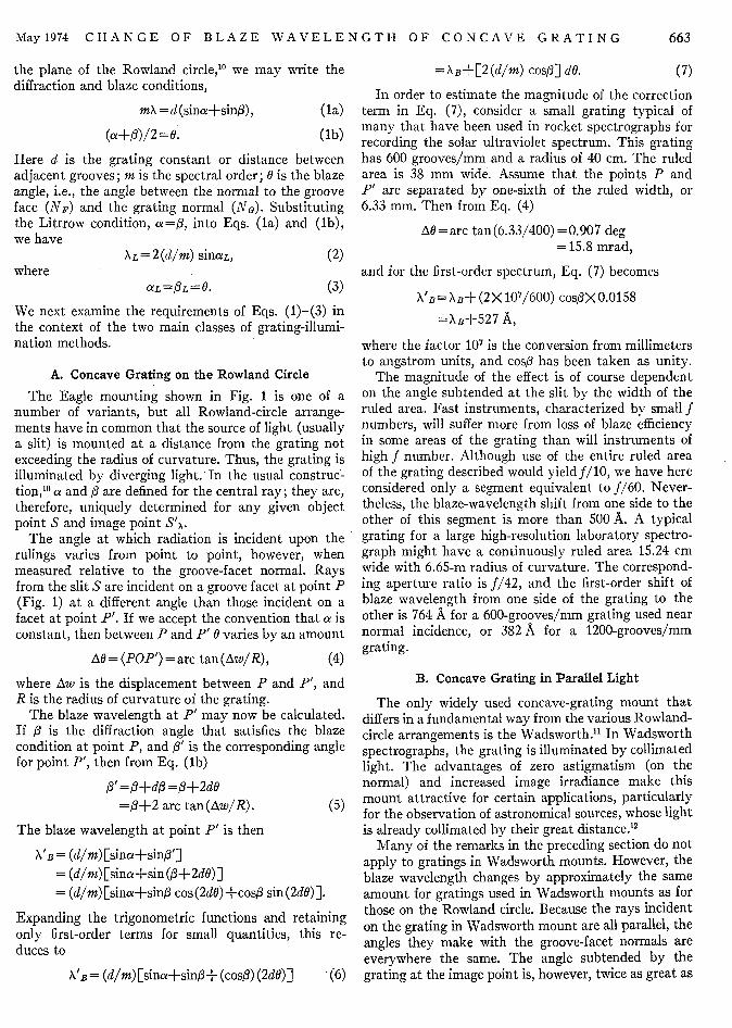
In order to estimate the magnitude of the correctionterm in Eq. (7), consider a small grating typical ofmany that have been used in rocket spectrographs forrecording the solar ultraviolet spectrum. This gratinghas 600 grooves/mm and a radius of 40 cm. The ruledarea is 38 mm wide. Assume that the points P andP' are separated by one-sixth of the ruled width, or6.33 mm. Then from Eq. (4)
AO=arc tan(6.33/400)=0.907 deg= 15.8 mrad,
and for the first-order spectrum, Eq. (7) becomes
XB = XB+ (2 X 10⁷/600) cosfX 0.0158
=XB+ 5 2 7 A,
where the factor 107 is the conversion from millimetersto angstrom units, and cosf has been taken as unity.
The magnitude of the effect is of course dependenton the angle subtended at the slit by the width of theruled area. Fast instruments, characterized by small fnumbers, will suffer more from loss of blaze efficiencyin some areas of the grating than will instruments ofhigh f number. Although use of the entire ruled areaof the grating described would yieldf/10, we have hereconsidered only a segment equivalent to f/60. Never-theless, the blaze-wavelength shift from one side to theother of this segment is more than 500 A. A typicalgrating for a large high-resolution laboratory spectro-graph might have a continuously ruled area 15.24 cmwide with 6.65-m radius of curvature. The correspond-ing aperture ratio is f/42, and the first-order shift ofblaze wavelength from one side of the grating to theother is 764 A for a 600-grooves/mm grating used nearnormal incidence, or 382 A for a 1200-grooves/mmgrating.
B. Concave Grating in Parallel Light
The only widely used concave-grating mount thatdiffers in a fundamental way from the various Rowland-circle arrangements is the Wadsworth." In Wadsworthspectrographs, the grating is illuminated by collimatedlight. The advantages of zero astigmatism (on thenormal) and increased image irradiance make thismount attractive for certain applications, particularlyfor the observation of astronomical sources, whose lightis already collimated by their great distance.'
Many of the remarks in the preceding section do notapply to gratings in Wadsworth mounts. However, theblaze wavelength changes by approximately the sameamount for gratings used in Wadsworth mounts as forthose on the Rowland circle. Because the rays incidenton the grating in Wadsworth mount are all parallel, theangles they make with the groove-facet normals areeverywhere the same. The angle subtended by thegrating at the image point is, however, twice as great as
663

DONALD J. MICHELS
I- ZR/2-Z
FIG. 2. Grating in Wadsworth mount.
that subtended by the same grating at an i]near the normal on the Rowland circle, bfocal length in the Wadsworth mount is appR/2, or half the Rowland normal focal dista
The Wadsworth mount is shown in Figof blaze wavelength, X, incident on the grais diffracted in the direction of speculartoward S'x. For light incident on the rulingsdiffracted rays are shown. One, of wavelEdiffracted to the monochromatic image pcray of different wavelength, indicated by Iline, is diffracted in the direction of specula(toward S'B). The angle between these rays
AO = (PS'xP')= arc tan (Aw/ (R/2)'
For the image at S'B, we can then write
fl'=i3+A0,3B+2 arc tan(Aw/R),
Figure 3 shows the results of such a measurement on agrating of the type described in Sec. I A. The verticalscale is calibrated directly in grating efficiency, i.e., theratio of irradiance diffracted in the direction of observa-
-. - - tion to the irradiance of the grating surface.' 6 Thehorizontal scale represents displacement across theruled area. A millimeter scale is included.
Grating manufacturers, long aware of the continuouschange of blaze wavelength across the rulings, some-times partially compensate for the effect by resettingthe diamond angle at intervals during the ruling ofcertain gratings. Because present technology cannotaccomplish phase matching after such resetting, theresulting grating consists of two or three separaterulings on a single blank; the resolving power cannotexceed that of any one of the ruling panels, but the
nage point irradiance of the spectrum may be substantiallyecause the improved.roximately The grating shown here, Bausch & Lomb No.nce.13 573A10, is a tripartite aluminum replica. The dimen-
r. 2. LightLting at P,
reflectionat P', twongth X, ismint S'k. Athe brokenr reflectionis
I.
(8)
which is identical to Eq. (5) for the Rowland-circlemount. The remainder of the calculation is the same asit was for the other case, and the blaze-wavelength shiftfor a given linear displacement across the rulings isthe same, to within the limits of the approximationsintroduced in Eqs. (6) and (8).
II. EXPERIMENTAL OBSERVATION OFBLAZE-WAVELENGTH SHIFT
The apparatus developed at the Naval ResearchLaboratory for evaluation of optical grating perform-ance in the vacuum ultraviolet has recently beendescribed."4 It consists of an optical system that illumi-nates the test grating with a narrow monochromaticbeam. The grating efficiency at a given wavelength isrecorded as a function of position on the rulings bymoving the grating along a carefully machined trackin such a manner that the effect is a sliding motion ofthe grating over the surface of the sphere of which it isa segment. This method gives a point-by-point effi-ciency measurement in a mode of illumination thatclosely approximates a near-normal-incidence Rowland-circle mounting."
0-
-eo
U-
LU
0
38 mm |
FIG. 3. Tripartite grating, B&L No. 573A10. (Upper portion)Dimensions of the ruled area and of the light patch used to scanits surface. (Lower portion) Efficiency map of the grating at736 I The horizontal axis represents displacement across thegrating's ruled area. The distance scale is the same as in the upperpart of the figure. The small divisions beneath the horizontalaxis are 1 mm apart. At 736 A, each of the ruling panels shows adistinct maximum of efficiency near the center. Efficiency de-creases to about half the maximum at the edges of the panels.
664 Vol. 64
May1974 CHANGE OF BLAZE WAVELENGTH OF CONCAVE GRATING
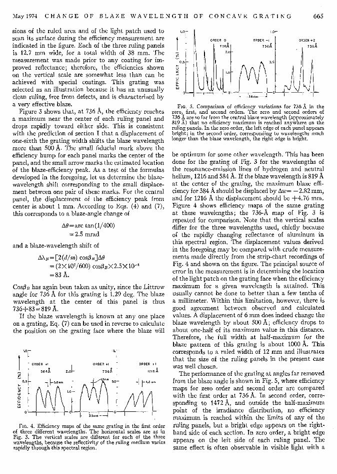
sions of the ruled area and of the light patch used toscan its surface during the efficiency measurement areindicated in the figure. Each of the three ruling panelsis 12.7 mm wide, for a total width of 38 mm. Themeasurement was made prior to any coating for im-proved reflectance; therefore, the efficiencies shownon the vertical scale are somewhat less than can beachieved with special coatings. This grating wasselected as an illustration because it has an unusuallyclean ruling, free from defects, and is characterized bya very effective blaze.
Figure 3 shows that, at 736 A, the efficiency reachesa maximum near the center of each ruling panel anddrops rapidly toward either side. This is consistentwith the prediction of section I that a displacement ofone-sixth the grating width shifts the blaze wavelengthmore than 500 A. The small fiducial mark above theefficiency hump for each panel marks the center of thepanel, and the small arrow marks the estimated locationof the blaze-efficiency peak. As a test of the formulasdeveloped in the foregoing, let us determine the blaze-wavelength shift corresponding to the small displace-ment between one pair of these marks. For the centralpanel, the displacement of the efficiency peak fromcenter is about 1 mm. According to Eqs. (4) and (7),this corresponds to a blaze-angle change of
AO= arc tan(1/400)
=2.5 mrad
and a blaze-wavelength shift of
AXB = [2 (d/m) COSI3B]AG
= (2 X 10⁷/600) COSO3B X 2.5 X 10-3
=83 A.
COSlB has again been taken as unity, since the Littrowangle for 736 A for this grating is 1.29 deg. The blazewavelength at the center of this panel is thus736+83 = 819 A.
If the blaze wavelength is known at any one placeon a grating, Eq. (7) can be used in reverse to calculatethe position on the grating face where the blaze will
1.0 10.
l ORDER +1 ORDER +1 ORDER +1
584A 2.0 -736A 1216A
0.5 j 38mm DLO -5 .* mm
w 1.0
00 K-0
FIG. 4. Efficiency maps of the same grating in the first orderof three different wavelengths. The horizontal scales are as inFig. 3. The vertical scales are different for each of the threewavelengths, because the reflectivity of the ruling medium variesrapidly through this spectral region.
1.0 1.0
ORDER 0 ORDER +1 ORDER +2
736A 7364 73642.0-
0.5 0.5
ZO O
00
FIG. 5. Comparison of efficiency variations for 736 A in thezero, first, and second orders. The zero and second orders of736 A are so far from the central blaze wavelength (approximately819 A) that no efficiency maximum is reached anywhere on theruling panels. In the zero order, the left edge of each panel appearsbright; in the, second order, corresponding to wavelengths muchlonger than the blaze wavelength, the right edge is bright.
be optimum for some other wavelength. This has beendone for the grating of Fig. 3 for the wavelengths ofthe resonance-emission lines of hydrogen and neutralhelium, 1216 and 584 A. If the blaze wavelength is 819 Aat the center of the grating, the maximum blaze effi-ciency for 584 A should be displaced by Aw= -2.82 mm,and for 1216 A the displacement should be +4.76 mm.Figure 4 shows efficiency maps of the same gratingat these wavelengths; the 736-A map of Fig. 3 isrepeated for comparison. Note that the vertical scalesdiffer for the three wavelengths used, chiefly becauseof the rapidly changing reflectance of aluminum inthis spectral region. The displacement values derivedin the foregoing may be compared with crude measure-ments made directly from the strip-chart recordings ofFig. 4 and shown on the figure. The principal source oferror in the measurement is in determining the locationof the light patch on the grating face when the efficiencymaximum for a given wavelength is attained. Thisusually cannot be done to better than a few tenths ofa millimeter. Within this limitation, however, there isgood agreement between observed and calculatedvalues. A displacement of 6 mm does indeed change theblaze wavelength by about 500 A; efficiency drops toabout one-half of its maximum value in this distance.Therefore, the full width at half-maximum for theblaze pattern of this grating is about 1000 A. Thiscorresponds to a ruled width of 12 mm and illustratesthat the size of the ruling panels in the present casewas well chosen.
The performance of the grating at angles far removedfrom the blaze angle is shown in Fig. 5, where efficiencymaps for zero order and second order are comparedwith the first order at 736 A. In second order, corre-sponding to 1472 A, and outside the half-maximumpoint of the irradiance distribution, no efficiencymaximum is reached within the limits of any of theruling panels, but a bright edge appears on the right-hand side of each section. In zero order, a bright edgeappears on the left side of each ruling panel. Thesame effect is often observable in visible light with a
665

DONALD J. MICHELS
grating held in the hand and illuminated by a brightlamp. Coupled with the elementary considerationsoutlined in the foregoing, it can frequently be used todispel doubts that sometimes arise regarding theorientation of the blaze of a grating.
III. DISCUSSION
Conventional ruling of concave diffraction gratingswith blaze angle constant relative to the optical axisproduced gratings whose blaze wavelength changescontinuously with displacement across the face of theruling. The effect can be large, even for spectrographsof moderate aperture ratios. In fast instruments, withlow f numbers, most of the light that forms the spectralimage for a particular wavelength may come from adifferent portion of the grating ruling than that whichdiffracts light into the image for another wavelength.This possibility should be taken into account in apply-ing various focusing procedures. For example, it some-times happens, especially in the ultraviolet, that thelight source available for focusing emits over onlya small portion of the bandwidth covered by theinstrument. Optimizing the focus for this limitedwavelength region assures that the slit and image lieon a Rowland circle tangent to the grating face at thecenter of that portion of the ruling where the blazeis optimal for these wavelengths. Images formed inlight of other wavelengths, diffracted predominantlyfrom other portions of the grating, may not lie on thesame focal curve. The effect of varying blaze wave-length should also be considered in designing the coatingand partial masking of gratings for certain applications,in the initial choice of blaze angle, and in estimates ofthe maximum resolving power that can be expectedat a given wavelength.
In this paper, formulas have been developed thatrelate the blaze-wavelength shift to the grating con-stant, radius of curvature, and ruling width. Efficiencymeasurements on a typical grating have illustrated theeffect. Agreement is good between calculated andexperimentally measured blaze shifts.
ACKNOWLEDGMENTS
The author would like to express his sincere apprecia-tion to S. G. Tilford and W. R. Hunter of the NavalResearch Laboratory for reading the manuscript andoffering many helpful suggestions, and to E. G. Loewenof the Bausch & Lomb Diffraction Grating Laboratoryfor his assistance and encouragement. A portion of thiswork was supported by the National Aeronautics andSpace Administration under NASA Grant No. R-107.
REFERENCES
'E. G. Loewen, Director, Bausch & Lomb Diffraction GratingLaboratory (private communication).
2R. W. Wood, Phil. Mag. 20, 770 (1910).'Lord Rayleigh's suggestion is mentioned without reference by
R. W. Wood in Physical Optics, 3rd ed. (Macmillan, NewYork, 1934), p. 264.
4G. W. Stroke, in Handbuch der Phtysik, Vol. 29, edited by S.FilUgge (Springer, Berlin, 1967), pp. 426-754; cf. especiallypp. 570-599.
5R. C. McPhedran and M. D. Waterworth, Opt. Acta 20, 177(1973).
6J. A. R. Samson, J. Opt. Soc. Am. 52, 525 (1962).'R. J. Meltzer, in Applied Optics and Optical Engineering, Vol.
5, edited by R. Kingslake (Academic, New York, 1969), pp.65-67.
8A. Eagle, Astrophys. J. 31, 120 (1910); cf. also T. Namioka,J. Opt. Soc. Am. 49, 460 (1959).
'Diffraction Grating Handbook (Bausch & Lomb, Rochester,N. Y., 1970), pp. 23-26.
0T. Namioka, J. Opt. Soc. Am. 49, 446 (1959). As Namiokapoints out, the Rowland circle is but a special case of a moregeneral Rowland cylinder.
"1F. L. 0. Wadsworth, Astrophys. J. 3, 47 (1896)."R. Tousey, Space Sci. Rev. 2, 3 (1963)."R. A. Sawyer, Experimiental Spectroscopy, 2nd ed. (Prentice-
Hall, New York, 1951), p. 137.14D. J. Michels, T. L. Mikes, and W. R. Hunter, Appl. Opt.
13, 1223 (1974).5G. W. Stroke (Ref. 4, p. 474.)"This definition differs from that used by Stroke (Ref. 4) and
some others, in that no attempt is made here to separate theefficiency of the ruling from the reflectivity of the ruledmaterial. Although it is customary to specify the efficiencyof gratings for the visible and infrared with reference to anideal mirror, such an approach poses grave experimentalproblems for far-ultraviolet optics, because ultraviolet reflect-ances are highly variable. The ratio used here is the quantityof practical importance to the grating user.
666 Vol. 64