Embed Size (px)
Citation preview

Page 1 of 69
Changes to the Florida Building Code-Residential, 6th Edition (2017)
Section Requirement Change
Chapter 1: Scope and Administration
R101.2
Scope
Scope revised to increase the maximum height of accessory structures to 3 stories. Previously, the definition of “Accessory Structure” limited these structures to not more than 2 stories. This definition has also been revised.
Exception 1 has been revised to limit the applicability to Live/work units that are located in townhouses.
Chapter 2: Definitions
R202
Definitions: Accessory Structure
Definition revised to remove technical criteria. Section R101.2 increases the maximum height of accessory structures from 2 stories to 3 stories.
R202
Definitions: Alternating Tread Device
New definition added for alternating tread device consistent with the definition in the FBCB.
R202
Definitions: Alteration
Definition revised to building, electrical, gas and plumbing systems to the scope of the definition.

Page 2 of 69
R202
Definitions: Attic
Definition revised to clarify that an attic can be on parts of a building other than the just the top story.
R202 Definitions: Backflow Preventer Definition revised for clarity and consistency with the FBCP.
R202
Definitions: Building-integrated Photovoltaic Product
New definition applicable to products that incorporate PV modules and functions as a component of the building envelope.
R202 Definitions: Circulating Hot Water System New definition.
R202
Definitions: Collection Pipe
New definition applicable to unpressurized pipe that drains nonpotable water to a storage tank by gravity.
R202 Definitions: Conditioned Space Definition revised for clarity and consistency with the FBCEC and FBCM.
R202
Definitions: Contamination
Definition revised to clarify that contamination of the water supply is a high hazard or health hazard impairment of the quality of potable water.

Page 3 of 69
R202 Definitions: Continuous Insulation New definition applicable to the residential provisions of the FBCEC.
R202 Definitions: Cross-laminated Timber New definition applicable to prefabricated engineered wood products.
R202 Definitions: Direct System New definition applicable to a type of solar heating system.
R202 Definitions: Drain-back System New definition applicable to a type of solar heating system.
R202 Definitions: Engineered Wood Rim Board New definition applicable to a specific prefabricated engineered wood product.
R202 Definitions: ERI Reference Design New definition applicable to the residential provisions of the FBCEC.
R202 Definitions: Factory-made Air Duct New definition added.
R202
Definitions: Fiber-cement (Backerboard, Siding, Soffit, Trim and Underlayment) Products
Definition revised to be consistent with ASTM C 1154 which governs these types of products.

Page 4 of 69
R202 Definitions: Fire Separation Distance Definition revised to clarify that the fire separation distance measurement for zero lot line
developments on apply to jurisdictions that permit zero lot line developments.
R202 Definitions: Flexible Air Connector New definition added for a term used in the code.
R202
Definitions: Gypsum Board
New definition added for a term used in the code. Definition is consistent with the way the term is defined in the FBCB.
R202
Definitions: Gypsum Panel Product
New definition added for a term used in the code. Definition is consistent with the way the term is defined in the FBCB.
R202
Definitions: Historic Building
New definition added for a term used in the code. Definition is consistent with the way the term is defined in the FBCB.
R202 Definitions: Indirect System New definition applicable to a type of solar heating system.
R202 Definitions: Insulated Siding New definition added for a type of continuous insulation.

Page 5 of 69
R202
Definitions: Insulated Vinyl Siding
New definition added for a vinyl cladding product with manufacturer-installed foam plastic insulating material.
R202 Definitions: Masonry Unit Definition revised to include architectural cast stone as a masonry unit.
R202
Definitions: Mechanical Joint
New definition for describing what constitutes a mechanical connection between pipes, fitting, or pipes and fittings.
R202
Definitions: Metal Roof Panel, or Metal Roof Shingle Manufacturer
New definition describing the party responsible for forming sheet metal raw materials into the metal roof panels and/or shingles.
R202
Definitions: Mezzanine
Definition revised for consistency with the FBCB and new provisions in Section R325 for mezzanines.
R202
Definitions: Nailable Substrate New definition applicable to new provisions added to Chapter 7 for exterior wall coverings.
R202 Definitions: On-site Nonpotable Water Reuse Systems New definition applicable to new provisions in Section P2911

Page 6 of 69
R202
Definitions: Photovoltaic Module
New definition added for a term used in the code. Definition is consistent with the way the term is defined in the FBCB.
R202
Definitions: Photovoltaic Panel
New definition added for a term used in the code. Definition is consistent with the way the term is defined in the FBCB.
R202
Definitions: Photovoltaic Panel System
New definition added for a term used in the code. Definition is consistent with the way the term is defined in the FBCB.
R202 Definitions: Photovoltaic Shingles Definition revised for clarity and consistency with the FBCB.
R202 Definitions: Plumbing Systems Definition revised for consistency with the FBCP.
R202 Definitions: Polypropylene Side New definition for a new exterior wall cladding now regulated by Chapter 7.
R202
Definitions: Pollution
Definition revised to enable a better determination of the type of backflow prevention assembly, backflow prevention device, means or method required.

Page 7 of 69
R202 Definitions: Reclaimed Water New definition applicable to new provisions in Section P2913
R202
Definitions: Registered Design Professional
Definition revised to clarify that the term includes and design professional so long as they are practicing with the scope of their license.
R202 Definitions: Roof Replacement New definition applicable to the reroofing provisions of Chapter 9.
R202 Definitions: Shingle Fashion New definition describing the method of applying moisture control layers such as roof underlayment and water-resistive barriers.
R202 Definitions: Stairway, Spiral New definition for spiral stairway consistent with the definition in the FBCB.
R202
Definitions: Townhouse
Revised to limit townhouses to a maximum of 3 stories to be consistent with Florida Statutes.
R202
Definitions: Waste Receptor
New definition added for a term used in the code. Definition is consistent with the way the term is defined in the FBCP.

Page 8 of 69
R202 Definitions: Plastic Composite Definition revised for clarity.
Chapter 3: Building Planning
R301.2.1.1 Wind limitations and wind design required
Revised to clarify that specific prescriptive provisions in the FBC-R do not apply to construction in the State of Florida. In previous editions of the FBC-R, the prescriptive provisions that did not apply were deleted. In the FBC-R 6th Edition (2017) those prescriptive provision remain in the code but Section R301.2.1.1 state that they do not apply where Vult equals or exceeds 115 m[j (all of Florida). The prescriptive provisions include Sections R502, R503, R505, R602, R603, R606s, R802, and R804. New language clarifies that the roof sheathing attachment provisions of Section R803 do not apply.
R301.2.1.1.1 Sunrooms Section revised to clarify the applicable loads on elements that qualify as components and cladding and those that qualify as part of the main wind-force resisting system.
Table R301.2(2)
Component and Cladding Loads for a Building with a Mean Roof Height of 30 feet Located in Exposure B (ASD)
Design and wind pressures in the table have been adjusted to ASD-level loads. New Note f clarifies that the pressures have already been multiplied by 0.6 to convert them to ASD-level loads.
R301.2.1.2 Protection of openings
Exception for using wood structural panels for opening protection in wind-borne debris regions has been revised based on research funded by the Florida Building Commission. The maximum span is reduced from 8 feet to 44 inches. New prescriptive attachment methods are provided for wood, masonry, and concrete construction. The prescriptive fastening table has been deleted.
Table R301,2,1,2
Wind-borne Debris Protection Fastening Schedule for Wood Structural Panels
Table deleted.

Page 9 of 69
R301.2.1.2 Basic wind speed Section requiring wind speed lines to be determined by local ordinance using recognized physical landmarks such as major roads, canals, rivers and lake shores has been deleted.
R301.2.4 Floodplain construction New language adds buildings sustaining substantial damage. Specifies buildings and structures located in more than one flood hazard area are to comply with the most restrictive flood hazard area provisions.
Table R301.7
Allowable Deflection of Structural Members
Table revised to clarify the exterior wall deflection limits are due to wind loads. Also revised to clarify that the allowable deflection for ceilings with flexible finishes, which includes gypsum wallboard, is L/240. Note a has been revised for consistency with the tabulation of ASD-level wind pressures in Table R301.2(2).
R302.1 Exterior walls (fire resistant construction)
Exception 7 has been revised to clarify that the zero lot line exception only applies Where zero lot line construction is permitted by local regulations.
Table
R302.1
Exterior Walls
New Note b permits required the roof-eave fire-resistance rating to be omitted where fireblocking is installed. New Note c permits required the roof-eave fire-resistance rating to be omitted where gable vent openings are not installed.
R302.2.2 Parapets for townhouses The exception has been revised to require that the Class C rating of the roof covering has to be determined by tests in accordance with ASTM E 108 or UL 790.
R302.6 Dwelling-garage fire separation New language added requiring that gypsum board required in Table R302.6 is required to be attached in accordance with Table R702.3.5.
R302.10.1 Insulation (flame spread and smoke- developed index) Exception 2 is revised to specifically state cellulose fiber loose-fill insulation.

Page 10 of 69
R302.11.1 Fireblocking materials Item 8 revised to require cellulose insulation to be tested in accordance with ASTM E 119 or UL 263.
R302.13 Fire protection of floors
Provisions relocated from Chapter 5 to have all fire resistance provisions in one location. Provisions require a membrane to be placed on underside of floor framing members and addresses requirements for materials. Provisions apply to floors not required elsewhere in code to provide a fire resistance rating. New language is added allowing penetrations including ducts, vents, electrical outlets, lighting and other items.
R303.1 Habitable rooms Revised to permit the use of skylights for natural ventilation.
R303.5.1 Intake openings Section editorially reformatted for clarity.
R303.7 Interior stairway illumination
Stairway illumination requirements divided into 2 sections for clarity.
R303.8 Exterior stairway illumination
R304.1 Minimum area
The requirement that all dwelling units have at least one habitable room with a floor area of not less than 120 square feet has been deleted. Minimum area of 70 square feet for other rooms, except kitchen, retained.
R304.2
Other rooms
Page 11 of 69
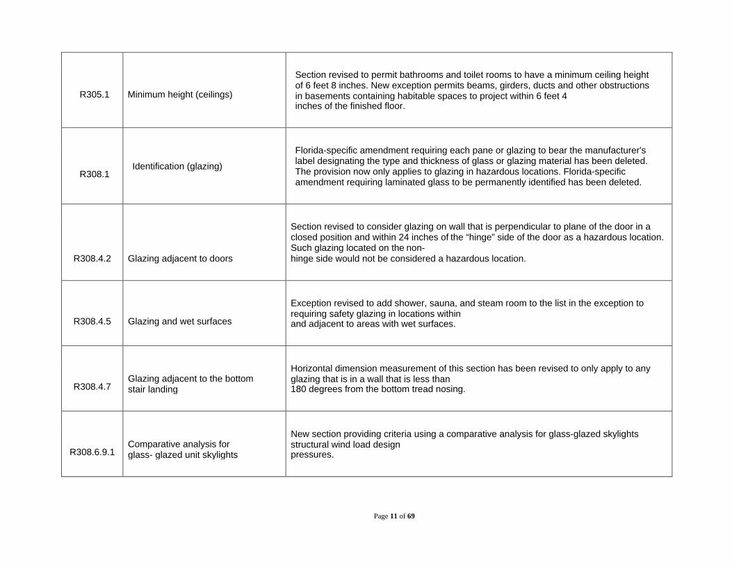
R305.1 Minimum height (ceilings)
Section revised to permit bathrooms and toilet rooms to have a minimum ceiling height of 6 feet 8 inches. New exception permits beams, girders, ducts and other obstructions in basements containing habitable spaces to project within 6 feet 4 inches of the finished floor.
R308.1
Identification (glazing)
Florida-specific amendment requiring each pane or glazing to bear the manufacturer's label designating the type and thickness of glass or glazing material has been deleted. The provision now only applies to glazing in hazardous locations. Florida-specific amendment requiring laminated glass to be permanently identified has been deleted.
R308.4.2
Glazing adjacent to doors
Section revised to consider glazing on wall that is perpendicular to plane of the door in a closed position and within 24 inches of the “hinge” side of the door as a hazardous location. Such glazing located on the non- hinge side would not be considered a hazardous location.
R308.4.5
Glazing and wet surfaces
Exception revised to add shower, sauna, and steam room to the list in the exception to requiring safety glazing in locations within and adjacent to areas with wet surfaces.
R308.4.7
Glazing adjacent to the bottom stair landing
Horizontal dimension measurement of this section has been revised to only apply to any glazing that is in a wall that is less than 180 degrees from the bottom tread nosing.
R308.6.9.1
Comparative analysis for glass- glazed unit skylights
New section providing criteria using a comparative analysis for glass-glazed skylights structural wind load design pressures.

Page 12 of 69
R310
Emergency escape and rescue openings
Section reorganized for clarity and to clarify the doors are also a viable emergency escape and rescue option.
R310.1.1
Operational constraints and opening control devices
New language permits the use of window opening control devices on windows serving as required emergency escape and rescue openings.
R310.2.5 Replacement windows
New section exempting replacement windows from the minimum sill height requirements for emergency escape and rescue openings provided the replacement window meets the following criteria: 1. Window is manufacturer’s largest standard size window that will fit within the existing frame or existing rough opening. 2. The replacement window is the same operating style as the existing window or a style allowing an equal or greater opening than the existing window. 3. The replacement window is not part of a change of occupancy.
R310.5 Dwelling additions New section requiring dwelling additions that contain sleeping rooms or basements to have an emergency escape and rescue opening. Two exceptions are provided.
R310.6 Alterations or repairs of existing basements
New section stating that an emergency escape and rescue opening is not required for a basement undergoing an alteration or repair unless new sleeping rooms are created.
R311.1 Means or egress Section revised to clarify the required egress is required to open directly into a public way or to a yard or court that opens to a public way.
R311.3.2 Floor elevations for other exterior doors
Exception revised to clarify that the top landing is not required in accordance with the exception.
Page 13 of 69
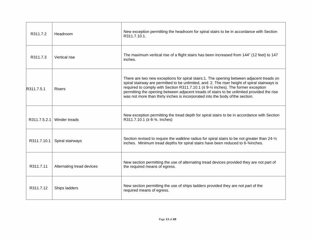
R311.7.2 Headroom New exception permitting the headroom for spiral stairs to be in accordance with Section R311.7.10.1.
R311.7.3 Vertical rise The maximum vertical rise of a flight stairs has been increased from 144” (12 feet) to 147 inches.
R311.7.5.1 Risers
There are two new exceptions for spiral stairs:1. The opening between adjacent treads on spiral stairway are permitted to be unlimited, and: 2. The riser height of spiral stairways is required to comply with Section R311.7.10.1 (≤ 9-½ inches). The former exception permitting the opening between adjacent treads of stairs to be unlimited provided the rise was not more than thirty inches is incorporated into the body of the section.
R311.7.5.2.1
Winder treads
New exception permitting the tread depth for spiral stairs to be in accordance with Section R311.7.10.1 (≥ 6-¾. Inches)
R311.7.10.1 Spiral stairways Section revised to require the walkline radius for spiral stairs to be not greater than 24-½ inches. Minimum tread depths for spiral stairs have been reduced to 6-¾inches.
R311.7.11
Alternating tread devices
New section permitting the use of alternating tread devices provided they are not part of the required means of egress.
R311.7.12 Ships ladders New section permitting the use of ships ladders provided they are not part of the required means of egress.

Page 14 of 69
R311.8.1 Maximum slope (ramps) Revised to require only ramps serving the required egress door to have a maximum slope of 1:12. All other ramps are permitted to have a maximum slope of 1:8.
R312.1.1 Where required (guards) The horizontal location of guards from the open side has been changed from within 36 inches to the open side to within 24 inches of the open side.
R312.1.2 Height The requirement to consider adjacent fixed seating when measuring the height of guards has been deleted.
R312.2.1 Window sills Section covering window fall protection is reorganized for clarity. Exceptions are revised to apply to windows whose openings will not allow the passage of a 4-inch-diameter sphere, windows with fall protection complying with ASTM F 2090, and windows with window opening control devices complying with Section R312.2.2.
R314 Smoke alarms Section reorganized in a more logical order for clarity.
R314.4.3
Location
New language requires smoke alarms to be installed not less than 3 feet from the door or opening of a bathroom that contains a bathtub or shower.
R314.3.1 Installation near cooking appliances New section limiting the location of smoke alarms with respect to cooking appliances.
Surface burning characteristics Revised to require the product to also be tested in the maximum density as well as

Page 15 of 69
R316.3 (foam plastic) the maximum thickness.
R316.4
Thermal barrier
Section revised to permit the use of 23/32- inch wood structural panel as a thermal barrier.
R316.5.3 Attics Section reorganized to clarify that the thermal barrier is not required when foam plastic insulation is tested in accordance with Section R316.6. 1/4 -inch fiber cement panel, soffit or backer board is added as an ignition barrier.
R316.5.4
Crawl spaces
Section reorganized to clarify that the thermal barrier is not required when foam plastic insulation is tested in accordance with Section R316.6.
R316.5.11 Sill plates and headers Section revised to allow the use of spray- applied foam in the perimeter of joist spaces without a thermal barrier.
R316.5.12
Sheathing
New language requires foam plastic insulation used as an exterior wall sheathing to comply with the wind resistance requirements of new Section R316.8.
R316.8
Wind resistance
New section requiring foam plastic insulation used as an exterior wall sheathing to comply with SBCA FS 100 for wind resistance.
R317.1.4
Wood columns
New exception added for deck posts supported by concrete piers or metal pedestals projecting not less than 1 inch above a concrete floor or 6 inches above exposed earth.

Page 16 of 69
R317.3
Fasteners and connectors in contact with preservative-treated and fire- retardant-treated wood
Revised to require stainless steel driven fasteners to be in accordance with ASTM F 1667.
R319 Site address Section revised to require address numbers to be alphanumeric and not be spelled out.
R322.1 General (flood-resistant construction) Section revised to add Coastal A zone, substantial improvement and restoration of substantial damage to the scope of this section. Requires buildings and structures located in more than one flood hazard area to comply with most restrictive flood hazard area.
R322.1.5 Lowest floor Revised for clarity and to match NFIP regulations.
R322.1.8 Flood-resistant materials Revised to require materials used below the elevations required in Section R322.2 or R322.3 to be in accordance with FEMA TB-2.
R322.2 Flood hazard areas (including A zones) Revised to require Coastal A zones to comply with Section R322.3.
R322.2.1 Elevation requirements (A zones) Expands requirement to elevate lowest floors to or above the base flood elevation (BFE) plus 1 foot or the design flood elevation (DFE), whichever is higher to all flood hazard areas. Formerly applied solely to Coastal A Zones.

Page 17 of 69
R322.2.2 Enclosed area below design flood elevation Section reorganized to put all of the installation requirements in a separate section,
separating installation from the requirements that apply to the openings themselves. Clarifies that the area of enclosures is to be measured from the outside and that the net open area calculation has to take into account if there are louvers, blades, screens and faceplates because their presence affects the flow of water.
R322.2.2.1 Installation of openings.
R322.2.4
Tanks
New section specifying anchorage requirements for underground and above- ground tanks
R322.3
Coastal high-hazard areas (including V Zones and Coastal A Zones, where designated)
Revised to add Coastal A Zones to the scope of this section.
R322.3.2 Elevation requirements (V zones and Coastal A zones)
Expands requirement to Coastal A Zone and modifies requirement from elevating the lowest structural members supporting floors to or above the DFE. Modified to require lowest structural member supporting floors to be elevated to the base flood elevation (BFE) plus 1 foot or the design flood elevation (DFE), whichever is higher.
R322.3.3 Foundations New exception for stem wall foundations supporting a floor system in Coastal A zones that meet the requirements of the exception.
R322.3.4
Walls below design flood elevation New language requires walls intended to break away under flood loads to have flood openings that meet the criteria in Section R322.2.2, Item 2.

Page 18 of 69
R322.3.5.1
Protection of building envelope
New section requiring exterior doors that comply with the wind load requirements of Section R609 to be installed at the top of stairs that provide access to the building and that are enclosed with walls designed to break away.
R322.3.7
Tanks New section specifying anchorage requirements for underground and above- ground tanks
R324
Solar Energy Systems
New section providing general requirements for solar energy systems including roof- mounted photovoltaic systems, building- integrated photovoltaic systems, and ground-mounted photovoltaic systems.
R325
Mezzanines
New section providing criteria related to mezzanine size, height, means of egress, and openness based on the mezzanine provisions in the FBCB.
R326 Swimming Pools, Spas and Hot Tubs New general section requiring that the design of pools and spas to comply with Chapter 45.
Chapter 4: Foundations
R402.2.1 Materials for concrete New general section referencing Section R608.5.1 for concrete materials.
R402.4
Masonry
New section requiring masonry to have a minimum specified compressive strength of 1500 psi.

Page 19 of 69
Table R403.1(1)
Minimum Width and Thickness for Concrete Footings for Light-Frame Construction
The prescriptive provisions for minimum size of concrete footings based on gravity loads have been revised by replacing the existing Table R403.1 with three new tables that account for additional roof live load conditions and additional load bearing values of soil.
Table R403.1(2)
Minimum Width and Thickness for Concrete Footings for Light-Frame Construction with Brick Veneer
Table
R403.1(3)
Minimum Width and Thickness for Concrete Footings with Cast-In-Place Concrete or Fully Grouted Masonry Wall Construction
R403.1.6 Foundation anchorage Section revised to clarify the foundation anchorage requirements for cold-form steel framing. Requires anchor bolts to be located in the middle third of the width of the plate.
R404.1.1 Design of masonry foundation walls The reference to NCMA TR68 A for the design and construction of masonry foundation walls has been deleted.
Table R404.1.1
(1) Plain Masonry Foundation Walls The minimum thickness for wall heights of 8 and 9 feet were revised to be consistent with
TMS 402/ACI 530/ASCE 5 section 5.6.3 and Table 5.6.3.1.
R404.4 Retaining walls
Revised to increase the limits for when retaining walls have to be design. The scope now applies to retaining walls that retain in excess of 48 inches of unbalanced fill or retaining walls that exceed 24 inches in height. New language clarifies that this section does not apply to foundation walls supporting buildings.

Page 20 of 69
R405.1 Concrete or masonry foundations (foundation drainage)
New language limiting the use of filter membranes on perforated drains where not recommended by the drain manufacturer.
R406.1
Concrete or masonry foundation dampproofing
Section revised to require foundation walls that retain earth and enclose interior spaces and floors below grade to be dampproofed from the higher of “(a) the top of the footing or (b) 6 inches below the top of the basement floor.”
R406.2 Concrete or masonry foundation waterproofing
Section revised to require in areas with a high-water table or other severed soil-water conditions are known to exist, foundation walls that retain earth and enclose interior spaces and floors below grade to be waterproofed from the higher of “(a) the top of the footing or (b) 6 inches below the top of the basement floor.”
Chapter 5: Floors
R502.1.1
Sawn lumber
Section revised to clarify the process by which lumber design values are certified and recognized in the code.
R502.1.4 Structural log members Section revised to require structural log members to comply with ICC-400.
R502.1.6
Cross-laminated timber
New section requiring cross-laminated timber to manufactured and identified as required by ANSI/APA PRG 320.
Page 21 of 69
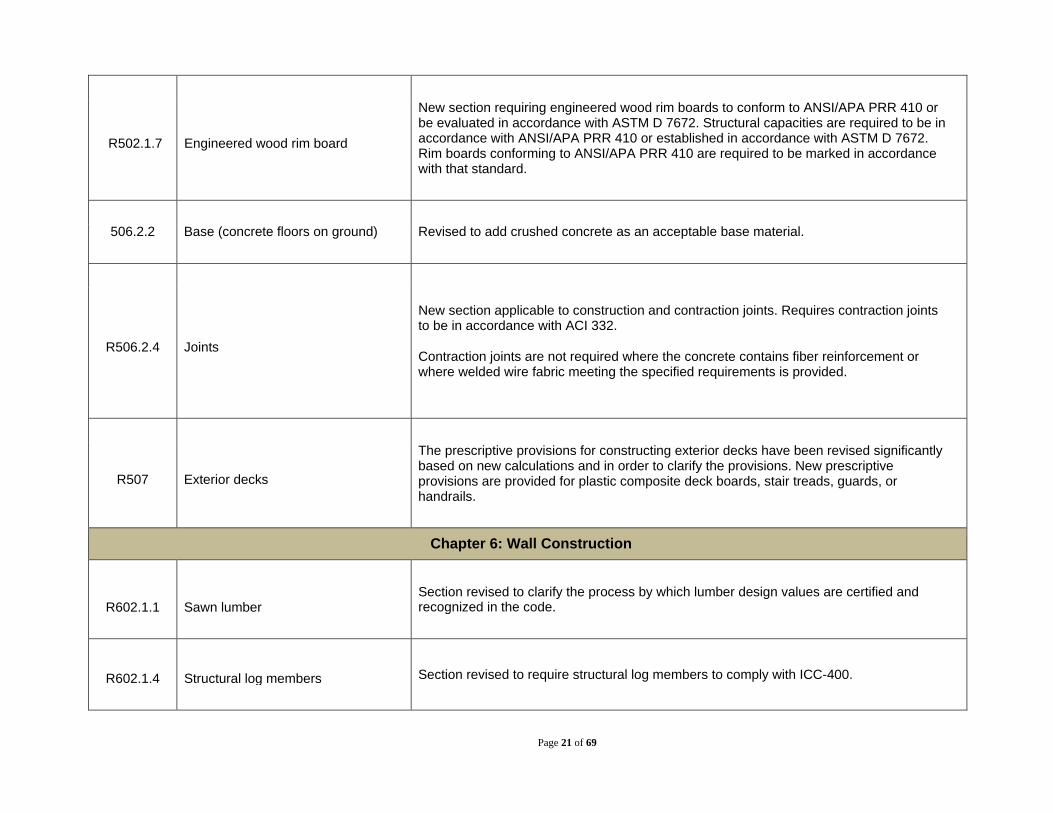
R502.1.7 Engineered wood rim board
New section requiring engineered wood rim boards to conform to ANSI/APA PRR 410 or be evaluated in accordance with ASTM D 7672. Structural capacities are required to be in accordance with ANSI/APA PRR 410 or established in accordance with ASTM D 7672. Rim boards conforming to ANSI/APA PRR 410 are required to be marked in accordance with that standard.
506.2.2 Base (concrete floors on ground) Revised to add crushed concrete as an acceptable base material.
R506.2.4 Joints
New section applicable to construction and contraction joints. Requires contraction joints to be in accordance with ACI 332. Contraction joints are not required where the concrete contains fiber reinforcement or where welded wire fabric meeting the specified requirements is provided.
R507 Exterior decks
The prescriptive provisions for constructing exterior decks have been revised significantly based on new calculations and in order to clarify the provisions. New prescriptive provisions are provided for plastic composite deck boards, stair treads, guards, or handrails.
Chapter 6: Wall Construction
R602.1.1
Sawn lumber
Section revised to clarify the process by which lumber design values are certified and recognized in the code.
R602.1.4 Structural log members Section revised to require structural log members to comply with ICC-400.

Page 22 of 69
R602.1.6 Cross-laminated timber New section requiring cross-laminated timber to manufactured and identified as required by ANSI/APA PRG 320.
R602.1.7 Engineered wood rim board
New section requiring engineered wood rim boards to conform to ANSI/APA PRR 410 or be evaluated in accordance with ASTM D 7672. Structural capacities are required to be in accordance with ANSI/APA PRR 410 or established in accordance with ASTM D 7672. Rim boards conforming to ANSI/APA PRR 410 are required to be marked in accordance with that standard.
R602.1.9 Particleboard New section requiring particleboard to conform to ASTM A208.1.
R602.1.10 Fiberboard New section requiring fiberboard to conform to ASTM C 208.
R604.3 Installation (wood structural panels) Language recognizing wood structural panels marked Exposure 1 or Exterior as water-repellant sheathing has been deleted as wood structural panels are not recognized as a weather-resistive barrier.
Page 23 of 69
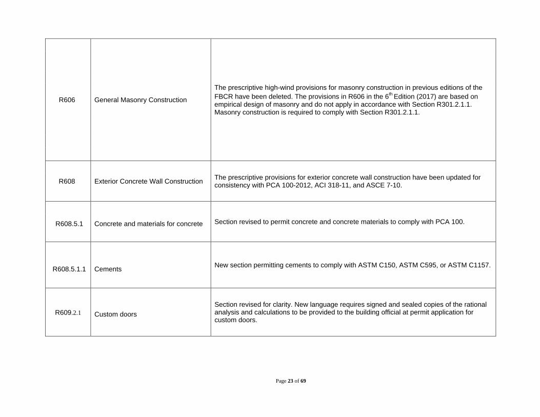
R606 General Masonry Construction
The prescriptive high-wind provisions for masonry construction in previous editions of the FBCR have been deleted. The provisions in R606 in the 6th Edition (2017) are based on empirical design of masonry and do not apply in accordance with Section R301.2.1.1. Masonry construction is required to comply with Section R301.2.1.1.
R608 Exterior Concrete Wall Construction The prescriptive provisions for exterior concrete wall construction have been updated for consistency with PCA 100-2012, ACI 318-11, and ASCE 7-10.
R608.5.1 Concrete and materials for concrete Section revised to permit concrete and concrete materials to comply with PCA 100.
R608.5.1.1
Cements New section permitting cements to comply with ASTM C150, ASTM C595, or ASTM C1157.
R609.2.1 Custom doors Section revised for clarity. New language requires signed and sealed copies of the rational analysis and calculations to be provided to the building official at permit application for custom doors.
Page 24 of 69
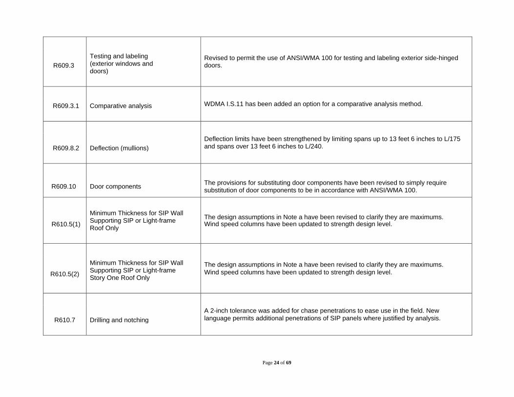
R609.3
Testing and labeling (exterior windows and doors)
Revised to permit the use of ANSI/WMA 100 for testing and labeling exterior side-hinged doors.
R609.3.1 Comparative analysis WDMA I.S.11 has been added an option for a comparative analysis method.
R609.8.2
Deflection (mullions)
Deflection limits have been strengthened by limiting spans up to 13 feet 6 inches to L/175 and spans over 13 feet 6 inches to L/240.
R609.10 Door components The provisions for substituting door components have been revised to simply require substitution of door components to be in accordance with ANSI/WMA 100.
R610.5(1)
Minimum Thickness for SIP Wall Supporting SIP or Light-frame Roof Only
The design assumptions in Note a have been revised to clarify they are maximums. Wind speed columns have been updated to strength design level.
R610.5(2)
Minimum Thickness for SIP Wall Supporting SIP or Light-frame Story One Roof Only
The design assumptions in Note a have been revised to clarify they are maximums. Wind speed columns have been updated to strength design level.
R610.7
Drilling and notching
A 2-inch tolerance was added for chase penetrations to ease use in the field. New language permits additional penetrations of SIP panels where justified by analysis.

Page 25 of 69
R614
Combined Concrete, Masonry, or ICF and Wood Exterior Wall Construction
Section deleted.
Chapter 7: Wall Covering
R702.3.3 Cold-formed steel framing (gypsum board)
Section revised to require nonload-bearing cold-formed steel to also comply with AISI S220 and load-bearing cold-formed steel to also comply with AISI S200.
Table R702.3.5
Minimum Thickness and Application of Gypsum Board
Note e, which required the use of 5/8” Type X gypsum board on garage ceilings when there are habitable rooms above has been relocated to a new row directly in the table for clarity.
R702.3.7 Water-resistant gypsum backing board
Section revised to delete the requirement that limits framing spacing for water- resistant gypsum backing board installed on ceilings to not exceed 12 inches on center for 1/2-inch-thick or 16 inches for 5/8-inch- thick gypsum board.
R702.4.2 Backer board
Section reorganized to reference permitted backer board materials in a new table for clarity.
Table R702.4.2 Backer Board Materials

Page 26 of 69
Table R702.7.1 Class III Vapor Retarders
Insulated sheathing is replaced with Continuous sheathing for consistency with new definition in Chapter 2 and ASHRAE 90.1. The use of spray foam in accordance with Note a has been revised to deleted the minimum density of 2 lbs/ft3 and replaced with a maximum permeance of 1.5 perms.
R703.1 General (exterior covering) New exception added for log walls designed and constructed in accordance with ICC 400.
R703.1.2 Wind resistance Section revised to clarify that wall coverings, backing materials, and their attachments have to be designed for wind loads based on wall loads and an effective wind area of 10 square feet.
R703.1.2.1 Wind resistance of soffits Section revised to clarify that soffits and their attachments have to be designed for wind loads based on wall loads and an effective wind area of 10 square feet.
R703.2 Water-resistive barrier Exceptions 2 and 3 have been deleted as they are addressed elsewhere in the code.
Table R703.3(1)
Siding Minimum Attachment and Thickness
Entire table has been reformatted and reorganized. Many of the table notes have been relocated as new sections for clarity.
R703.5 Wood, hardboard and wood structural panel siding
Revised to require hardboard siding used as architectural trim to comply with CPA/ANSI A 135.7.

Page 27 of 69
R703.3.3 Attachment Section deleted. Wood, hardboard and wood structural panel siding required to be installed in accordance with Table R703.3(1).
R703.3.4 Minimum thickness (wood, hardboard and wood structural panel siding)
Section deleted. Wood, hardboard and wood structural panel siding required to be the minimum thickness specified in accordance with Table R703.3(1).
R703.3 Nominal thickness and attachments Section reorganized as part of reorganization of Table R703.3(1). New language clarifies that the attachment requirements Table R703.3(1) are for wood frame construction. New language refers to New Table R703.3(2) for cold-formed steel frame construction.
R703.3.1 Wind limitations Wind limitations to using the prescriptive siding attachment table have been located to a new section. References new Table R703.3.1 in addition to a maximum design pressure of 30 psf.
Table R703.3.1
Limits for Attachment Per Table R703.3.1
New table specifies maximum heights for using the prescriptive siding attachment table based on wind speed and exposure.
Table
R703.3.2
Optional Siding Attachment Schedule for Fasteners Where No Stud Penetration Necessary
New table providing prescriptive attachment for exterior wall coverings to wood structural panel sheathing in lieu of driving fasteners directly into studs.
Table R703.3(2)
Screw Fastener Substitution for Siding Attachment to Cold-formed Steel Light Frame Construction
New table providing screw substitution sizes for cold-form steel based on the nail sizes specified in Table R703.3(1)

Page 28 of 69
R703.6.1
Application (wood shakes and shingles)
The minimum spacing required for expansion has been changed to 1/8 to ¼ inch for adjacent shingles and 3/8 to ½ inch for adjacent shakes.
R703.6.3 Attachment
Minimum fasteners permitted to be used for wood shake and shingle exterior wall coverings has been strengthened. New tables specify minimum fastener dimensions based on the product type.
Table R703.6.3(1) Single Course Sidewall Fasteners
Table R703.6.3(2) Double Course Sidewall Fasteners
R703.7.4 Application (exterior plaster) Exception for applications installed in accordance with ASTM C 926 has been revised to include the reference in ASTM C 926 Section 8 to Section X1.4.2 of the Appendix.
R703.7.5 Curing (exterior plaster) New exception for applications installed in accordance with ASTM C 926 and includes the reference in ASTM C 926 Section 8 to Section X1.4.2 of the Appendix.
R703.8 Anchored stone and masonry veneer, general
The term “anchored” has been added to the charging language to clarify the distinction between adhered veneers. The wind speed limiting the use of the prescriptive provisions of Section R703.8 has been changed from Vasd less than 130 mph to Vult less than 165 mph.
Figure R703.8 Typical Masonry Veneer Wall Details New footnote to the figure clarifies that Figure R703.8 provides typical construction details
and for actual mandatory requirements to see the indicated sections of text.

Page 29 of 69
R703.8.2.1 Support by steel angle Section revised to permit the steel angle supporting masonry to be anchored to cold- formed steel framing with the connections specified.
R703.8.2.2 Support by roof construction Section revised to permit the steel angle supporting masonry to be anchored to cold- formed steel framing with the connections specified.
R703.9.1 Exterior insulation and finish system (EIFS)
Section revised to clarify the EIFS systems without drainage are only permitted to be used over concrete or masonry wall assemblies.
R703.9.2 Exterior insulation and finish system (EIFS) with drainage
Section revised to clarify the EIFS systems with drainage are required on all wall assemblies except concrete or masonry wall assemblies. The provisions of Section R703.9.2.1, R703.9.2.2, R703.9.3, R703.9.4, R703.9.4.1, and R703.9.4.2 have been merged into Section R703.9.1 and R703.9.2 as applicable.
R703.10.1 Panel siding (fiber cement siding) Section revised to permit fiber cement panel siding to comply with ISO 8336, Category A, minimum Class 2.
R703.10.2 Lap siding (fiber cement siding) Section revised to permit fiber cement lap siding to comply with ISO 8336, Category A, minimum Class 2.
R703.11.1.1 Fasteners (vinyl siding)
Fastening requirements for vinyl siding have been clarified and relocated from Notes to Table R703.3(1) to stand-alone sections.
R703.11.1.2 Penetration depth (vinyl siding)

Page 30 of 69
R703.11.1.3 Spacing (vinyl siding)
R703.11.2 Installation over foam plastic sheathing (vinyl siding)
Section revised to include insulated vinyl siding to the scope of this section. Requires vinyl siding to have a wind pressure rating in accordance with new Table R703.11.2 when installed over foam plastic sheathing.
Table
R703.11.2
Adjusted Minimum Design Wind Pressure Requirement for Vinyl Siding
The adjustment factors for the design wind pressure rating for vinyl siding installed over foam plastic sheathing have been deleted and new Table R703.11.2 specifies minimum design wind pressure ratings based on wind speed, exposure, and whether interior gypsum wallboard installed or not. The new required design wind pressure ratings are calculated using the previous adjustment factors.
R703.13 Insulated vinyl siding New section requiring insulated vinyl siding to comply with ASTM D 7793. New subsection requires insulated vinyl siding and accessories to be installed in accordance with the manufacturer’s instructions.
R703.14 Polypropylene siding New section requiring polypropylene siding to comply with ASTM D 7254. New subsections address installation, fastener requirements, and fire separation.
R703.15 Cladding attachment over foam sheathing to wood framing
New section providing prescriptive requirements for attaching cladding over foam sheathing to wood framing. New Tables R703.15.1 and R703.15.2 specify maximum foam thicknesses of foam sheathing for direct attachment to framing and attachment to furring respectively.
R703.16 Cladding attachment over foam sheathing to cold-formed steel framing
New section providing prescriptive requirements for attaching cladding over foam sheathing to cold-formed steel framing. New Tables R703.15.1 and R703.15.2 specify maximum foam thicknesses of foam sheathing for direct attachment to framing and

Page 31 of 69
attachment to furring respectively.
R703.17 Cladding attachment over foam sheathing to masonry or concrete wall construction.
New section providing prescriptive requirements for attaching cladding over foam sheathing to masonry or concrete wall construction.
Chapter 8: Roof-Ceiling Construction
R802.1.1
Identification
Section revised to clarify the process by which lumber design values are certified and recognized in the code.
R802.1.3 Structural log members Section revised to require structural log members to comply with ICC-400.
R802.1.6 Cross-laminated timber New section requiring cross-laminated timber to manufactured and identified as required by ANSI/APA PRG 320.
R802.1.7 Engineered wood rim board
New section requiring engineered wood rim boards to conform to ANSI/APA PRR 410 or be evaluated in accordance with ASTM D 7672. Structural capacities are required to be in accordance with ANSI/APA PRR 410 or established in accordance with ASTM D 7672. Rim boards conforming to ANSI/APA PRR 410 are required to be marked in accordance with that standard.
R802.10.2.1 Applicability limits (wood trusses) New language limits truss roof framing constructed in accordance with this section sites subjected to a maximum wind speed of 140 mph for Exposure B or C.

Page 32 of 69
R803.2.3.1 Sheathing fastenings (roof sheathing) The minimum dimensional requirements for ring shank nails have been deleted and replaced with a reference to RSRS-01 nails in accordance with ASTM F1667.
R806.1 Ventilation required (roof ventilation) Exception permitting attic ventilation to not be required when determined not necessary by the code official due to atmospheric or climatic conditions has been deleted.
R806.5 Unvented attic and unvented enclosed rafter assemblies
Section revised for clarity and to align the provisions with the FBCB.
Table R806.5 Insulation for Condensation Control
New Note b provides a calculation procedure to determine rigid board or air impermeable insulation R-values for roof assemblies that have different ceiling insulation R-values.
R807.1 Attic access Section revised to clarify that the volume of space required for an attic access is to be measured based on the actual usable space.
Chapter 9: Roof Assemblies
R903.2 Flashing New language clarifies that flashing is required to be used to seal roofing systems where the system is interrupted or terminated
R904.5.1 Nails Section revised to include TAS 114 Appendix E for corrosion resistance and delete ASTM A641 reference which is a requirement in ASTM F1667.

Page 33 of 69
R904.5.3 Clips Section revised to require stainless steel clips to conform to ASTM A240/A240M
R905.1.1 Underlayment
New section for underlayment. Underlayment requirements for all roof coverings consolidated into a single location in Section R905.1.1. Requires compliance with Table R905.1.1 for standards, application, and attachment, New Exception provides for the use of synthetic underlayment and requires approval as an alternate to ASTM D 226 Type II and a minimum tear strength of 20 lbs. in accordance with ASTM D 1970 or SATM D 4533. Attachment is required to comply with the appropriate method of Table R905.1.1 applicable to the type roof covering and slope. Metal cap nails are required where Vult equals or exceeds 150 mph.
Table R905.1.1 Underlayment Table
Required type, installation, and fastening requirements for underlayment for roof coverings are consolidated into new Table R905.1.1. Underlayment complying with ASTM D 226 Type II or ASTM D 4869 Type IV (ASTM D 6757 for some roof coverings) is now required for all roof coverings where the roof slope is 4:14 and greater.
R905.2.4 Asphalt shingles ASTM D 225 has been deleted as an option for asphalt shingles
R905.2.5 Fasteners
New exception permits an alternate method of attachment complying with the wind load requirements of Chapter 16 of the Florida Building Code, Building if the architectural appearance is to be preserved from below. The alternative attachment is required to be prepared, signed and sealed by a Florida-registered architect or a Florida- registered engineer, which architect or engineer shall be proficient in structural design.
R905.2.6.1
Classification of asphalt shingles
Section revised to clarify that Shingles classified as ASTM D 3161 Class D or ASTM D 7158 Class G are acceptable for use where “Vasd is equal to or less than 100-mph.”
Page 34 of 69
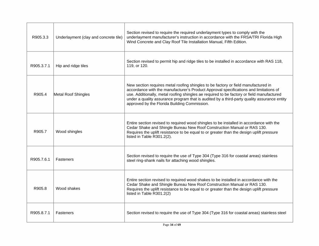
R905.3.3 Underlayment (clay and concrete tile) Section revised to require the required underlayment types to comply with the underlayment manufacturer’s instruction in accordance with the FRSA/TRI Florida High Wind Concrete and Clay Roof Tile Installation Manual, Fifth Edition.
R905.3.7.1
Hip and ridge tiles
Section revised to permit hip and ridge tiles to be installed in accordance with RAS 118, 119, or 120.
R905.4 Metal Roof Shingles
New section requires metal roofing shingles to be factory or field manufactured in accordance with the manufacturer’s Product Approval specifications and limitations of use. Additionally, metal roofing shingles ae required to be factory or field manufactured under a quality assurance program that is audited by a third-party quality assurance entity approved by the Florida Building Commission.
R905.7 Wood shingles
Entire section revised to required wood shingles to be installed in accordance with the Cedar Shake and Shingle Bureau New Roof Construction Manual or RAS 130. Requires the uplift resistance to be equal to or greater than the design uplift pressure listed in Table R301.2(2).
R905.7.6.1 Fasteners Section revised to require the use of Type 304 (Type 316 for coastal areas) stainless steel ring-shank nails for attaching wood shingles.
R905.8 Wood shakes
Entire section revised to required wood shakes to be installed in accordance with the Cedar Shake and Shingle Bureau New Roof Construction Manual or RAS 130. Requires the uplift resistance to be equal to or greater than the design uplift pressure listed in Table R301.2(2)
R905.8.7.1 Fasteners Section revised to require the use of Type 304 (Type 316 for coastal areas) stainless steel

Page 35 of 69
ring-shank nails for attaching wood shakes.
R905.10 Metal Roof Panels
New section requires metal roofing panels to be factory or field manufactured in accordance with the manufacturer’s Product Approval specifications and limitations of use. Additionally, metal roofing panels ae required to be factory or field manufactured under a quality assurance program that is audited by a third-party quality assurance entity approved by the Florida Building Commission for that purpose.
R905.10.4 Attachment The specific fasteners previously required for metal roof panels are now only required in the absence of manufacturer’s installation instructions. For copper roofs, the use of copper (not hard) brass, and bronze fasteners are now permitted.
R905.14
Sprayed polyurethane foam roofing
Section revised to permit sprayed polyurethane foam roofing to be installed in compliance with RAS 109 and 109A.
R905.14.2 Material standards (sprayed polyurethane foam roofing)
Section revised to permit sprayed polyurethane foam insulation to comply with ASTM D 7425.
R905.14.3 Protective Coating Material Standards New table specifies applicable material standards for liquid protective coatings applied following the application of the foam.
Page 36 of 69
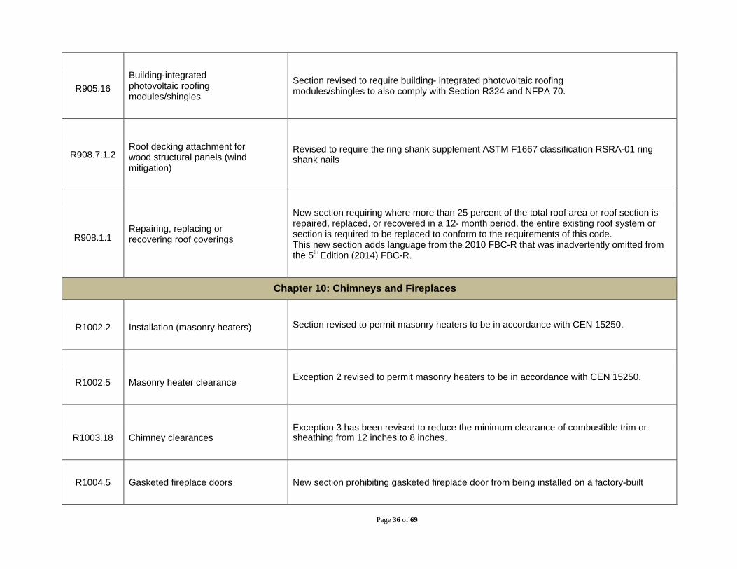
R905.16 Building-integrated photovoltaic roofing modules/shingles
Section revised to require building- integrated photovoltaic roofing modules/shingles to also comply with Section R324 and NFPA 70.
R908.7.1.2 Roof decking attachment for wood structural panels (wind mitigation)
Revised to require the ring shank supplement ASTM F1667 classification RSRA-01 ring shank nails
R908.1.1 Repairing, replacing or recovering roof coverings
New section requiring where more than 25 percent of the total roof area or roof section is repaired, replaced, or recovered in a 12- month period, the entire existing roof system or section is required to be replaced to conform to the requirements of this code. This new section adds language from the 2010 FBC-R that was inadvertently omitted from the 5th Edition (2014) FBC-R.
Chapter 10: Chimneys and Fireplaces
R1002.2 Installation (masonry heaters) Section revised to permit masonry heaters to be in accordance with CEN 15250.
R1002.5
Masonry heater clearance Exception 2 revised to permit masonry heaters to be in accordance with CEN 15250.
R1003.18
Chimney clearances
Exception 3 has been revised to reduce the minimum clearance of combustible trim or sheathing from 12 inches to 8 inches.
R1004.5 Gasketed fireplace doors New section prohibiting gasketed fireplace door from being installed on a factory-built

Page 37 of 69
fireplace except where the fireplace system has been specifically tested, listed and labeled for such use in accordance with UL 127.
R1006.2 Exterior air intake Section revised to require the exterior air intake to not be located at an elevation higher than the firebox for other than listed factory-built fireplaces.
R1006.5 Outlet Section revised to require the exterior air outlet shall be located in the back or side of the firebox chamber or be located outside of the firebox, at the level of the hearth and not greater than 24 inches (610mm) from the firebox opening.
Chapter 13: General Mechanical System Requirements
M1305.1 Appliance access for inspection service, repair and replacement
Requirement that room heaters have at least 18 inches of working space has been deleted.
M1305.1.3.1 Electrical requirements Section revised to require exposed lamps to be protected from damage by location of lamp guards.
M1305.1.4.3 Electrical requirements Section revised to require exposed lamps to be protected from damage by location of lamp guards.
M1306.2.1 Labeled assemblies (clearance reduction)
New section permitting reduced clearance using approved reduced clearance protective assemblies listed and labeled in accordance with UL 1618.

Page 38 of 69
M1308.2 Protection against physical damage
Section reorganized into 3 new sections for clarity. New section added addressing protection for piping based on the proximity to the piping to the edge of the face of the framing member to which a membrane will be attached.
M1308.2.1 Piping through bored holes or notches
M1308.2.2 Piping in other locations .
Chapter 14: Heating and Cooling Equipment and Appliances
M1401.1
Installation
Section revised to require air-handling units installed in attics to comply with Section R403.3.6 of the FBCEC.
M1401.3 Equipment and appliance sizing
Section revised to permit heating and cooling equipment and appliances to be sized in accordance with approved sizing methodologies other than ACCA Manual S. Two new exceptions permit heating and cooling equipment and appliances to not be limited to the capacities determined in accordance with Manual S where either of the listed criteria is met.
M1403.1 Heat pumps The minimum unobstructed total area of the outside and return air ducts or openings to a heat pump has been deleted. UL/CSA/ANCE 60335-2-40 has been added as option for listing and labeling heat pumps.
403.2 Foundations and supports Section deleted.

Page 39 of 69
M1410.1
General (vented room heaters)
Section revised to clarify that vented room heaters comply with ASTM E 1509 are for pellet-fuel burning.
M1410.2
Floor mounting
Exception 1 has been revised to required floor protectors to be listed and labeled in accordance with UL 1618.
M1411.3.2 Drain pipe materials and sizes Polybutylene has been deleted as a component of the condensate disposal system and PE-RT and polypropylene have been added. Section revised to clarify that the condensate waste and drain line size is required to be not less than ¾ inch nominal diameter.
M1411.3.3 Drain line maintenance New section requiring condensate drain lines to be configured to permit the clearing of blockages and performance of maintenance without requiring the line to be cut.
M1411.4 Condensate pumps New section requires condensate pumps located in uninhabitable spaces, such as attics and crawl spaces, to be connected to the appliance or equipment served such that when the pump fails, the appliance or equipment will be prevented from operating.
1411.6 Insulation of refrigerant piping Insulation for piping and fittings for refrigerant vapor lines has been changed to have a thermal resistivity of not less than R-4.
M1411.7 Location and protection of refrigerant piping
New section requiring refrigerant piping installed within 1 ½ inches of the underside of roof decks to be protected from damage caused by nails and other fasteners.

Page 40 of 69
M1411.8 Locking access port caps New exception for locking-type tamper- resistant caps if ports are located inside the condensing unit cabinet.
M1412.1 Approval of equipment (absorption systems)
Section revised to permit absorption systems to comply with UL/CSA/ANCE 60335-2-40.
M1413.1 General (evaporative cooling equipment
Section revised to permit evaporative cooling equipment and appliances to comply with UL/CSA/ANCE 60335-2-40.
Chapter 15: Exhaust Systems
M1502.4.1 Material and size (clothes dryer exhaust)
New exception permits exhaust ducts to be 4 inches nominal in diameter Schedule 40 PVC when horizontally run beneath the slab.
M1502.4.4 Dryer exhaust duct power ventilators New section requiring domestic dryer exhaust duct power ventilators to be listed and labeled to UL 705.
M1502.4.5.3 Dryer exhaust duct power ventilator New section limiting the length of dryer exhaust duct power ventilator in accordance with the manufacturer’s installation instructions.
M1502.4.6 Length identification Section revised to require identification of the exhaust duct equivalent length where the equivalent length exceeds 35 feet.

Page 41 of 69
M1503.2 Duct material Exceptions for using schedule 40 PVC pipe for ducts for domestic cooking appliances equipped with down-draft exhaust systems has been revised to require the PVC duct to extend not more than 8 inches above grade outside the building.
M1503.4 Makeup air required Section revised to clarify that makeup air can be mechanically or naturally provided. Also clarifies that electrically-operated and gravity dampers can be used to limit the amount of conditioned air that leaves the building when the exhaust is not running.
M1503.4.1 Location (kitchen exhaust makeup air)
New section requiring kitchen exhaust makeup air do be discharged into the same room in which the exhaust system is located or into rooms or duct systems that communicate through one or more permanent openings with the room in which such exhaust system is located. Openings are required to have a net cross-sectional area not less than the required area of the makeup air supply openings.
M1506.2 Duct length (exhaust ducts and exhaust openings)
New section requiring the length of exhaust and supply ducts used for ventilating equipment to not exceed the maximum lengths determined in accordance with new Table M1506.2. New exception to maximum duct length permitted when complying with the manufacturer’s design criteria and other method.
Table M1506.2
Duct Length
New table limiting duct length based on the type of duct, diameter, and flan airflow rating.
Chapter 16: Duct Systems
Table M1601.1.1
Duct Construction Minimum Sheet Metal Thickness for Single Dwelling Units
Table has been revised to recognize 30-gauge sheet metal as being appropriate for round ducts 14 inches or less diameter in single dwelling units. Consistent with the 2007 FBC-R.

Page 42 of 69
M1601.3 Duct insulation materials. Section revised to permit external reflective duct insulation in accordance with ASTM C 1668. Identification requirements also specified.
M1601.4.1 Joints, seams and connections
Section revised to clarify that “closure systems” are tapes and mastic. Also revised to require tapes and mastics used to seal fibrous glass ductwork shall be listed and labeled in accordance with UL 181A and be marked. Requires tapes and mastics used to seal metallic ducts shall comply with UL 181B and be marked. Language requiring round metallic ducts to be mechanically fastened has been deleted.
Exception 3 has been revised to state that snap-lock and button-lock do not qualify for the exception to additional closure systems.
M1601.4.2 Duct lap New section requiring crimp joints for round and oval metal ducts to be lapped not less than one inch and the male end of the duct to extend into the adjoining duct in the direction of airflow.
M1601.4.4 Support
Duct support materials and intervals have deleted. Factory made ducts listed in accordance with UL181 required to be supported in accordance with the manufacturer’s installation instructions. Field- and shop-fabricated fibrous glass ducts required to be supported in accordance the SMACNA Fibrous Glass Duct Construction Standards or the NAIMA Fibrous Glass Duct Construction Standards. Field- and shop fabricated metal and flexible ducts required to be supported in accordance with the SMACNA HVAC Duct Construction Standards—Metal and Flexible.
M1602.1 Outdoor air openings
Sections have been reorganized for clarity and to delete outdated language.
M1602.2 Return air openings
Chapter 18: Chimneys and Vents

Page 43 of 69
M1804.4 Door swing New section limiting the location of vent terminals to locations such that doors cannot swing within 12 inches horizontally of the vent terminals. Door stops and closures are not permitted to be used to obtain this clearance.
Chapter 19: Special Appliances, Equipment and Systems
M1901.3 Prohibited location Section prohibiting cooking appliances designed, tested, listed and labeled for use in commercial occupancies to not be installed within dwelling units or within any area where domestic cooking operations occur has been deleted.
Chapter 20: Boilers and Water Heaters
M2001.1.1 Standards (boilers) Standards for boilers have been updated.
M2002.5 Boiler low-water cutoff) New exception to the low-water cutoff control for coil-type and water-tube-type boilers that require forced circulation of water through the boiler and that are protected with a flow sensing control.
M2002.6 Operation Revised to require the low-water cutoff controls and flow sensing controls to automatically stop the combustion operation when water circulation stops.
M2005.1 General (water heaters) Section revised to require water heaters to be installed in accordance with Chapter 28.
Chapter 21: Hydronic Piping
Table Hydronic Piping Materials Polyethylene (PE) pipe, tubing and fittings (for ground source heat pump loop systems) have been removed from Table M2101.2 and relocated to new Section M2105 and Table
Page 44 of 69
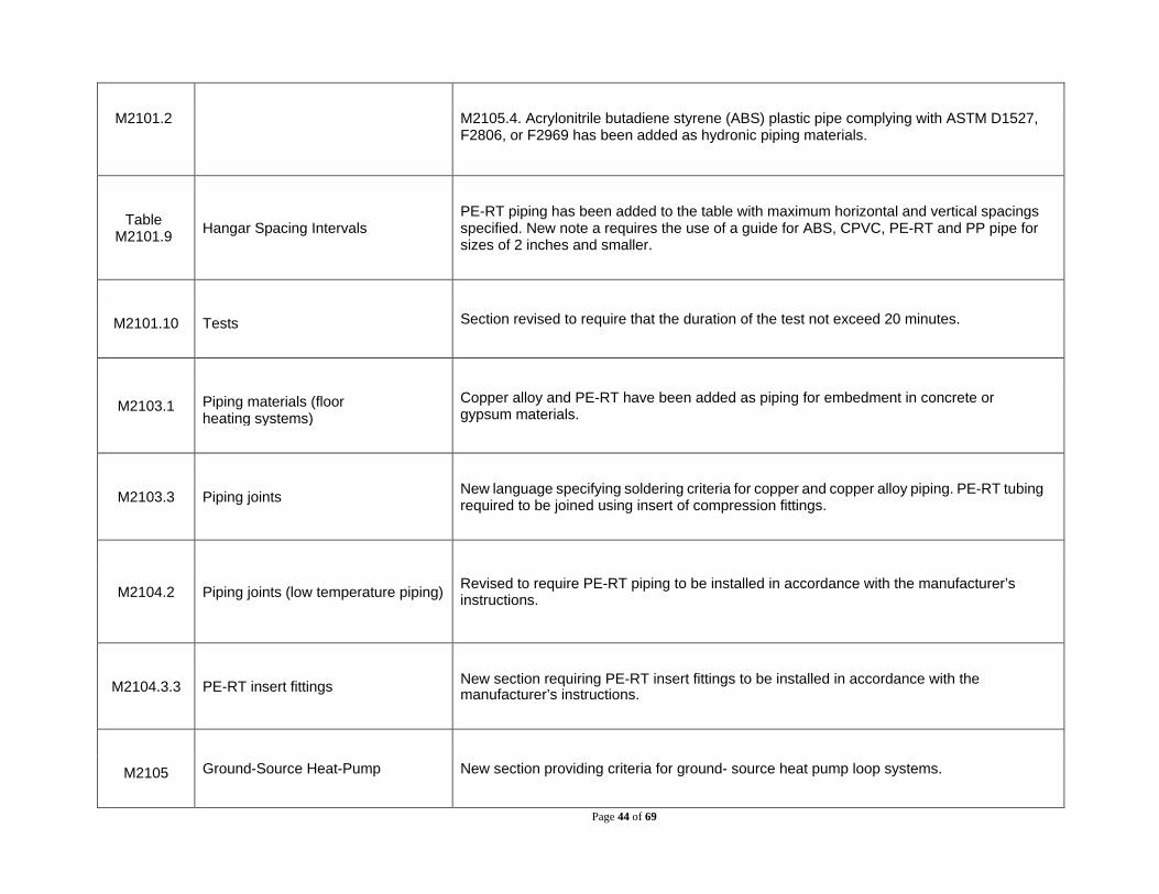
M2101.2 M2105.4. Acrylonitrile butadiene styrene (ABS) plastic pipe complying with ASTM D1527, F2806, or F2969 has been added as hydronic piping materials.
Table M2101.9 Hangar Spacing Intervals
PE-RT piping has been added to the table with maximum horizontal and vertical spacings specified. New note a requires the use of a guide for ABS, CPVC, PE-RT and PP pipe for sizes of 2 inches and smaller.
M2101.10 Tests Section revised to require that the duration of the test not exceed 20 minutes.
M2103.1 Piping materials (floor heating systems)
Copper alloy and PE-RT have been added as piping for embedment in concrete or gypsum materials.
M2103.3 Piping joints New language specifying soldering criteria for copper and copper alloy piping. PE-RT tubing required to be joined using insert of compression fittings.
M2104.2 Piping joints (low temperature piping) Revised to require PE-RT piping to be installed in accordance with the manufacturer’s instructions.
M2104.3.3 PE-RT insert fittings New section requiring PE-RT insert fittings to be installed in accordance with the manufacturer’s instructions.
M2105 Ground-Source Heat-Pump New section providing criteria for ground- source heat pump loop systems.

Page 45 of 69
System Loop Piping
Chapter 22: Special Piping and Storage Systems
M2202.1 Materials (oil piping, fitting and connections)
Copper alloy pipe has been added for oil piping, fittings, and connections.
Chapter 23: Solar Thermal Energy Systems
M2301.2 Design and installation Revised to clarify that Section M2301.2 also applies to the design of solar energy systems and that this section and its subsections apply specifically to thermal solar energy systems (not photovoltaics).
M2301.2.2 Collector sensors New section requiring collector sensor installation, location, and protection of wires from ultraviolet light to be in accordance with SRCC 300.
M2301.2.3 Pressure and temperature relief valves and system components
Section revised to clarify when temperature and pressure relief valves or pressure relief valves are required and refers to Section P2804 and SRCC 300 for additional requirements. It also requires that system components have a pressure rating that is not less than that of the setting of the pressure relief device.
M2301.5 Piping insulation New section requiring piping insulation to be in accordance with the FBCEC. Three exceptions apply.
M2301.2.7 Storage tank sensors New section requiring storage tank sensors shall comply with SRCC 300.

Page 46 of 69
M2301.2.8 Expansion tanks
Section revised to require expansion tanks in solar systems to be installed in solar collector loops that contain pressurized heat transfer fluid. Requires expansion tank systems to be design in accordance with SRCC 300. New exception for expansion tanks in drain-back systems.
M2301.2.10 Description and warning labels New section requiring solar thermal systems to comply with the description label and warning label requirements of Section M2301.2.11.2 and SRCC 300.
M2301.2.11.2 Drain and fill valve labels and caps New section requiring labels for drain and fill valve caps. Requires drain caps to be installed at drain and fill valves.
M2301.3.1 Collectors and panels Revised to require solar thermal collectors and panels to be listed and labeled in accordance with SRCC 100 or SRCC 600.
M2301.4 Heat transfer gasses or liquids and heat exchangers
Section revised to prohibit the use of ethylene glycol as a heat transfer fluid. Heat exchangers required to be in accordance with Section P2902.5.2 and SRCC 300. Requires heat transfer gases and liquids to be rated to withstand the system’s maximum design temperature under operating conditions without degradation.
M2301.6 Filtering New section requiring air provided to occupied spaces that passes through thermal mass storage systems by mechanical means to be filtered for particulates at the outlets of the thermal mass storage system.
M2301.7 Solar thermal systems for heating potable water New provisions addressing the use of solar thermal systems for heating potable water.
Page 47 of 69
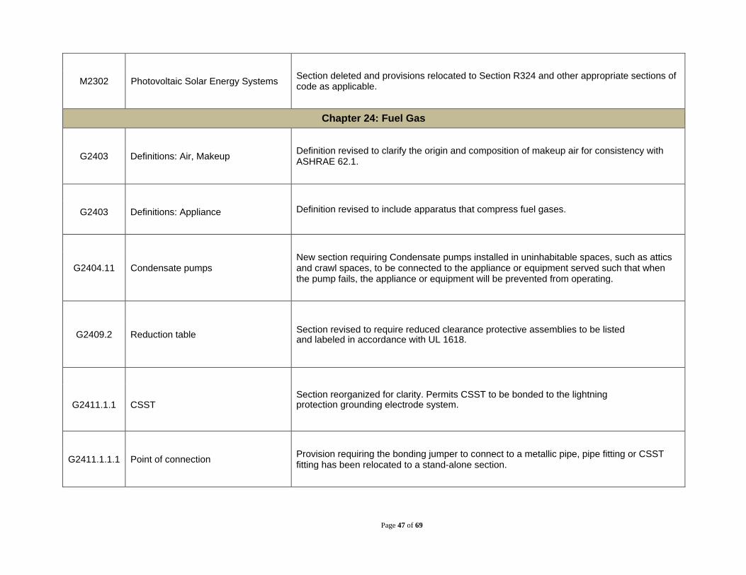
M2302 Photovoltaic Solar Energy Systems Section deleted and provisions relocated to Section R324 and other appropriate sections of code as applicable.
Chapter 24: Fuel Gas
G2403 Definitions: Air, Makeup Definition revised to clarify the origin and composition of makeup air for consistency with ASHRAE 62.1.
G2403 Definitions: Appliance Definition revised to include apparatus that compress fuel gases.
G2404.11 Condensate pumps New section requiring Condensate pumps installed in uninhabitable spaces, such as attics and crawl spaces, to be connected to the appliance or equipment served such that when the pump fails, the appliance or equipment will be prevented from operating.
G2409.2 Reduction table Section revised to require reduced clearance protective assemblies to be listed and labeled in accordance with UL 1618.
G2411.1.1
CSST
Section reorganized for clarity. Permits CSST to be bonded to the lightning protection grounding electrode system.
G2411.1.1.1 Point of connection Provision requiring the bonding jumper to connect to a metallic pipe, pipe fitting or CSST fitting has been relocated to a stand-alone section.

Page 48 of 69
G2411.1.1.2
Size and material of jumper
Provision requiring the bonding jumper to be no smaller than 6 AWG copper wire has been relocated to a stand-alone section.
G2411.1.1.3 Bonding jumper length New section limiting the length of the bonding jumper between the connection to a gas piping system and the connection to a grounding electrode system to 75 feet.
G2411.1.1.4 Bonding connections New section requiring bonding connections to be in accordance with NFPA 70.
G2411.1.1.5 Connection devices New section requiring devices used for making the bonding connection to be listed for the application in accordance with UL 467.
G2412.9 Identification
Exception to identifying pipe, tubing, and fittings has been revised to include steel pipe section 2 feet and less in length and cut from longer sections of pipe, steel pipe fittings 2 inches and less in size, where identification is provided on the packaging or crating, and where other approved documentation is provided.
G2412.10 Piping material standards New section requiring piping, tubing and fittings to be manufactured to the applicable criteria specified in Section G2414 and identified in accordance with Section G2412.9.
G2413.2 Maximum gas demand Reference to Table G2413.2 for estimating volumetric flow rate of gas when input ratings are not indicated has been deleted. Adjustment for altitude is now only required where the

Page 49 of 69
installation is above 2000 feet in elevation.
Table G2413.2
Approximate Gas Input for Typical Appliances Table deleted.
G2414.6 Plastic pipe, tubing and fittings New language prohibits the use of PVC and CPVC plastic pipe, tubing and fittings for supplying fuel gas.
G2410.10.4 Metallic fittings Brass fittings removed from the scope of this section. New criteria added for pipe fittings that are drilled and tapped in the field.
G2415.5 Fittings in concealed locations Section revised to specify the applicable standards for fittings listed for use in concealed locations. The prohibition on right and left couplings has been removed.
G2415.6 Underground penetrations Section revised to permit underground piping, where installed through the outer foundation or basement wall of a building, provided the piping is encased in a protective sleeve or protected by an approved device or method.
G2415.7 Protection against physical damage Section reorganized into 4 new sections for clarity. New section added addressing protection for piping based on the proximity to the piping to the edge of the face of the framing member to which a membrane will be attached.
G2415.7.1 Piping through holes or notches

Page 50 of 69
G2415.7.2 Piping installed in other locations
G2415.7.3 Shield plates
G2415.18 Pipe cleaning New section prohibiting the use of a flammable or combustible gas to clean or remove debris from a piping system.
G2417.5.1 Leak detection methods Language prohibiting the use of matches, candles, open flames or other methods that could provide a source of ignition has been deleted.
G2421.2 MP regulators Section revised to require additional criteria for MP regulators. Where MP regulators are connected to rigid piping, a union is required to be installed within 1 foot of either side of the MP regulator.
G2422.1 Connecting appliances Section revised to Add a requirement that a Z21.54 listed connector be used to connect portable outdoor appliances to the house piping system.
G2411.1.5
Movable appliances
Section revised to address movable appliances that are not commercial cooking appliances that would be subject to periodic moving.

Page 51 of 69
G2426.7.1 Door swing New section prohibiting appliance and equipment vent terminals from being located such that doors swing within 12 inches (305 mm) horizontally of the vent terminal. Door stops or closures are not permitted to be used to obtain this clearance.
G2427.4.1 Plastic piping Section revised to require appliances that use plastic piping for venting to be listed for use with such venting material and for the installation instructions to identify the specific plastic piping material.
G2427.6.9.3 Category II, III, and IV appliances New language added requiring that the sizing of plastic pipe that is specified by the appliance manufacturer as a venting material for Category II, III, and IV appliances to be in accordance with the manufacturer’s instructions.
G2427.8 Venting system termination location New clearance provisions have been added for category IV appliance side wall vent terminations to adjacent building openings.
G2439.4 Dryer exhaust duct power ventilators New section requiring domestic dryer exhaust duct power ventilators to be listed and labeled to UL 705 for use in dryer exhaust duct systems.
G2439.7.2 Duct installation Section revised to permit ducts to be joined with screws or similar fasteners provided they do no protrude more than 1/8 inch into the inside of the duct.
G2439.7.4.3 Dryer exhaust duct power ventilator length
New section permitting the maximum length of the exhaust duct to be determined by the dryer exhaust duct power ventilator manufacturer’s installation instructions.
Page 52 of 69
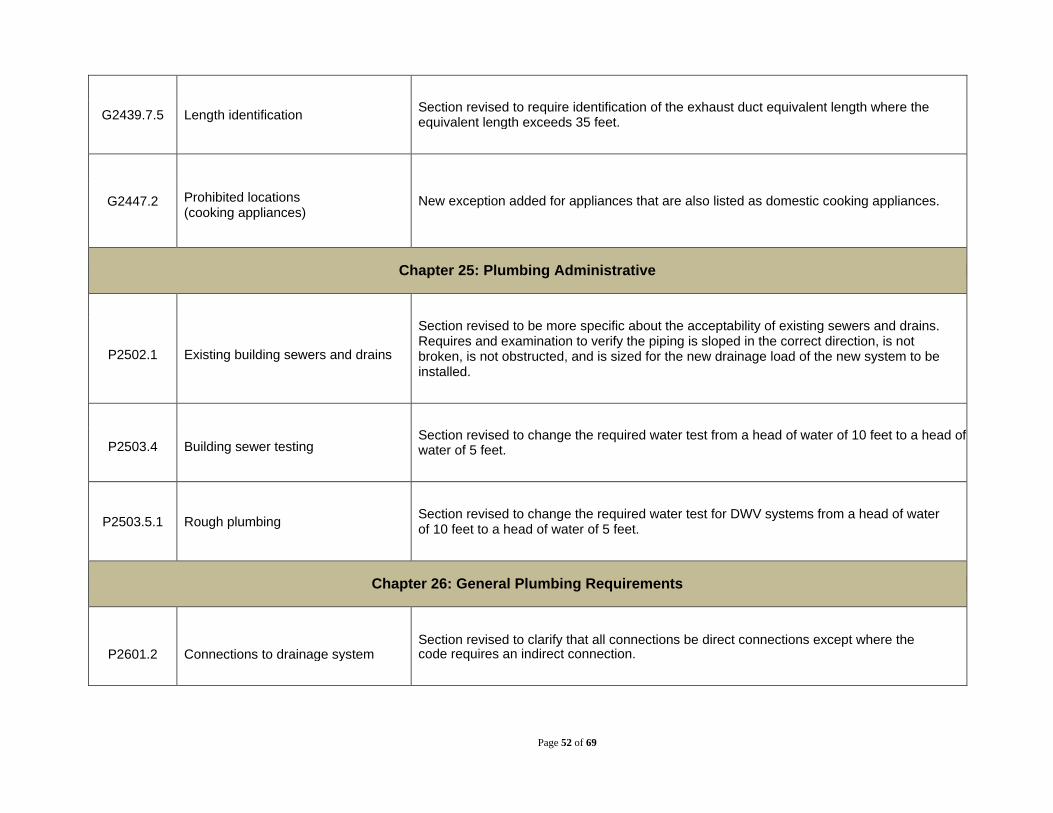
G2439.7.5 Length identification Section revised to require identification of the exhaust duct equivalent length where the equivalent length exceeds 35 feet.
G2447.2 Prohibited locations (cooking appliances)
New exception added for appliances that are also listed as domestic cooking appliances.
Chapter 25: Plumbing Administrative
P2502.1 Existing building sewers and drains
Section revised to be more specific about the acceptability of existing sewers and drains. Requires and examination to verify the piping is sloped in the correct direction, is not broken, is not obstructed, and is sized for the new drainage load of the new system to be installed.
P2503.4 Building sewer testing Section revised to change the required water test from a head of water of 10 feet to a head of water of 5 feet.
P2503.5.1 Rough plumbing Section revised to change the required water test for DWV systems from a head of water of 10 feet to a head of water of 5 feet.
Chapter 26: General Plumbing Requirements
P2601.2
Connections to drainage system
Section revised to clarify that all connections be direct connections except where the code requires an indirect connection.

Page 53 of 69
P2603.2.1
Protection against physical damage
For pipes installed through holes or notches in studs, joists or rafters, the minimum distance from the nearest edge that doesn’t require a shield plate has been reduced from 1½ inches to 1¼ inches.
P2603.3
Protection against corrosion
Section rewritten for clarity. Clarifies that Where sheathing protects piping that penetrates concrete or masonry walls or floors, the sheathing is required to be installed in a manner that allows movement of the piping within the sheathing.
P2604.4 Protection of footings Section revised to more specifically define the bearing plane.
Fig. 2604.4 Pipe Location with Respect to Footings Figure deleted.
Table P2605.1 Piping Support
PEX and PE-RT piping with diameters 1¼ and larger have been added to the table with maximum horizontal and vertical spacings. Brass piping material has been deleted as it is covered under copper alloys. Note b has been revised to specifically define what a mid-story guide is.
P2607.1 Pipes penetrating roofs Existing section has been separated into two sections for clarity. The phrase “watertight” has been deleted and replace with specific requirements for flashings and waterproof sealants.
P2607.2 Pipes penetrating exterior walls

Page 54 of 69
P2609.1 Identification (materials evaluation and listing)
New language permits nipples created from the cutting and threading of approved pipe to not be identified. New section permits identification to be printed on the item packaging or other documentation where pipe fittings and pipe nipples are too small to be marked with the manufacturer identification.
P2609.4 Third-party certification
Revised to clarify that only plumbing products and materials required by the code to be in compliance with a referenced standard are required to be listed by a third-party certification agency.
Chapter 27: Plumbing Fixtures
P2701.1 Quality of fixtures Section revised for clarity and to provide a direct reference to Table P2701.1
Table P2701.1
Plumbing Fixtures, Faucets and Fixture Fittings
Standard for plastic fixtures, ANSI Z24 has been revised to reflect Z24.1 and Z24.2 have been combined into a single standard.
P2702.1 Plumbing fixtures Exception has been revised to permit the strainer to be omitted on hub drains that receive clear water waste.
P2706.1 General (wasted receptors) Section revised to permit the strainer to be omitted on hub drains that receive clear water waste. Redundant language has been deleted. Exception 1 has been relocated as stand-alone Section P2706.1.1 for clarity.
P2706.1.1 Hub drains

Page 55 of 69
P2708.2 Shower drain New section requiring shower drains to have an outlet size of not less than 1½ inches in diameter.
P2709.2 Lining required (shower receptors)
A new exception has been added to the lining requirement: 3. Shower compartments where the finished shower drain is depressed a minimum of 2 inches (51 mm) below the surrounding finished floor on the first-floor level and the shower recess is poured integrally with the adjoining floor.
P2710.1
Shower walls
Revised to clarify that this section also applies to walls above bathtubs that have a wall-mounted shower head.
P2712.1 Approval (water closets) New language requires water closets equipped with a dual flushing tank to comply with ASME A112.19.14.
P2716.2 Water supply required Unenforceable language regarding adequate supply of water at a sufficient flow rate has been deleted.
P2717.1 Protection of water supply (dishwashing machines)
Section revised to provide references for compliance for the required air gap or backflow preventer. The air gap is required to comply with ASME A112.1.3 or A112.1.2. The backflow preventer is required to comply with Section P2902.
P2717.2 Sink and dishwasher Sections combined into a single section for clarity. Requires the combined discharge from a dishwasher and sink to be served by a trap of not less than 1½ inches in outside diameter.

Page 56 of 69
P2725 Nonliquid Saturated Treatment Systems
New section requiring nonliquid saturated treatment systems to comply with NSF 41.
P2716.2 Water supply required Unenforceable language regarding adequate supply of water at a sufficient flow rate has been deleted.
Chapter 28: Water Heaters
P2801.1 Required Section revised to more generally state that hot water is required to be supplied to plumbing fixtures and appliances intended for bathing, washing, or culinary purposes.

Page 57 of 69
P2802 Solar Water Heating Systems New section addressing mixing valves and isolation valves in solar thermal systems.
P2804.6.1 Requirements for discharge pipe
Item 10 has been revised to specify a minimum discharge piping termination of not less than two times the discharge pipe diameter above the flood level rim of the waste receptor. New Item 14 requires relief valve discharge piping construction PEX or PE-RT to be one nominal size larger than the size of the relief valve outlet.
Chapter 26: General Plumbing Requirements
P2901.2 Identification of nonpotable water systems
New section addressing identification of nonpotable water systems for safety reasons.
P2901.2.1 Signage required
P2901.2.2 Distribution pipe labeling and marking
P2901.2.2.1 Color
P2901.2.2.2 Lettering size
P2901.2.2.3 Identification tape
Page 58 of 69
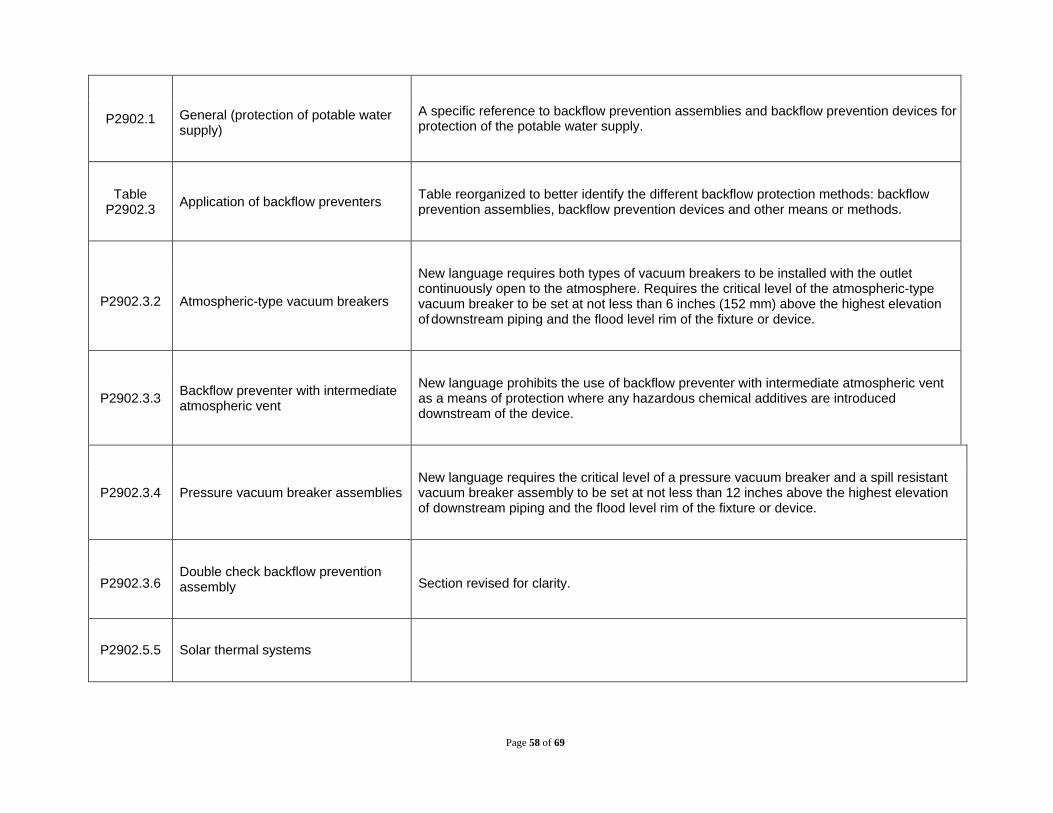
P2902.1 General (protection of potable water supply)
A specific reference to backflow prevention assemblies and backflow prevention devices for protection of the potable water supply.
Table P2902.3 Application of backflow preventers Table reorganized to better identify the different backflow protection methods: backflow
prevention assemblies, backflow prevention devices and other means or methods.
P2902.3.2 Atmospheric-type vacuum breakers
New language requires both types of vacuum breakers to be installed with the outlet continuously open to the atmosphere. Requires the critical level of the atmospheric-type vacuum breaker to be set at not less than 6 inches (152 mm) above the highest elevation of downstream piping and the flood level rim of the fixture or device.
P2902.3.3 Backflow preventer with intermediate atmospheric vent
New language prohibits the use of backflow preventer with intermediate atmospheric vent as a means of protection where any hazardous chemical additives are introduced downstream of the device.
P2902.3.4 Pressure vacuum breaker assemblies New language requires the critical level of a pressure vacuum breaker and a spill resistant vacuum breaker assembly to be set at not less than 12 inches above the highest elevation of downstream piping and the flood level rim of the fixture or device.
P2902.3.6 Double check backflow prevention assembly Section revised for clarity.
P2902.5.5 Solar thermal systems

Page 59 of 69
P2902.5.5.1 Indirect systems
Section revised to clarify that it applies to solar thermal systems. New sections have been added to clarify requirements for direct and indirect systems connected to potable or other than potable water distribution systems.
P2902.5.5.2 Direct systems for potable water distribution systems
P2902.5.5.3 Direct systems for other than potable water distribution systems.
Table P2903.1
Required Capacities at Point of Outlet Discharge
Minimum flow rates for lavatories, showers, and residential sinks have been reduced. New now permits the use of the manufacturer flow rate for shower mixing valves where it is lower than the minimum required by Table 403.1.
P2903.3 Minimum pressure
The minimum static pressure of 40 psf at the building entrance has been deleted. New language requires the use of an elevated water tank, a hydropneumatic pressure booster system or a water pressure booster pump where the water pressure supplied by the public water main or individual water supply system is insufficient to provide for the minimum pressures and quantities for the plumbing pressures in the building.
P2903.8 Gridded and parallel water distribution systems
Section revised to clarify that gridded systems are not permitted for hot water distribution systems.
P2903.8.3 Orientation Section deleted.
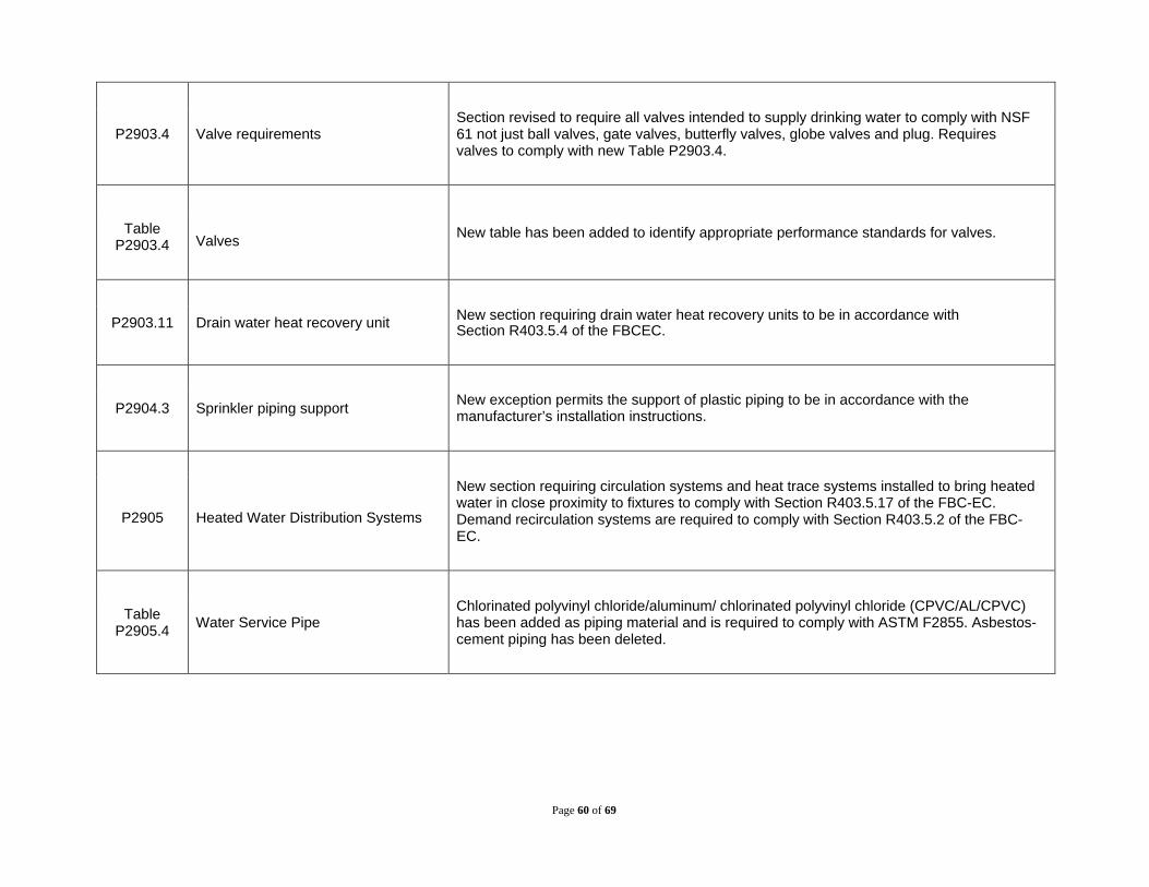
Page 60 of 69
P2903.4 Valve requirements Section revised to require all valves intended to supply drinking water to comply with NSF 61 not just ball valves, gate valves, butterfly valves, globe valves and plug. Requires valves to comply with new Table P2903.4.
Table P2903.4
Valves New table has been added to identify appropriate performance standards for valves.
P2903.11 Drain water heat recovery unit New section requiring drain water heat recovery units to be in accordance with Section R403.5.4 of the FBCEC.
P2904.3 Sprinkler piping support New exception permits the support of plastic piping to be in accordance with the manufacturer’s installation instructions.
P2905 Heated Water Distribution Systems
New section requiring circulation systems and heat trace systems installed to bring heated water in close proximity to fixtures to comply with Section R403.5.17 of the FBC-EC. Demand recirculation systems are required to comply with Section R403.5.2 of the FBC-EC.
Table P2905.4 Water Service Pipe
Chlorinated polyvinyl chloride/aluminum/ chlorinated polyvinyl chloride (CPVC/AL/CPVC) has been added as piping material and is required to comply with ASTM F2855. Asbestos-cement piping has been deleted.

Page 61 of 69
P2902.4 Dual check backflow preventer Terms clarified for consistency with ASSE 1024. Section relocated to section addressing other backflow preventers since the FBCR does not require a backflow preventer on the water supply system.
P2906.4.1 Separation of water service and building sewer Section revised and reorganized for clarity and consistency with the FBCP.
Table
P2906.5
Water Distribution Pipe
Chlorinated polyvinyl chloride/aluminum/ chlorinated polyvinyl chloride (CPVC/AL/CPVC) has been added as piping material and is required to comply with ASTM F2855.
Table P2906.6
Pipe Fittings
New standards for various types of pipe fittings have been added and inappropriate standards have been deleted.
P2905.9.1.2 CPVC plastic pipe Section reorganized for clarity.
P2906.9.1.3 CPVC/AL/CPVC pipe New section addressing joints in CPVC/AL/CPVC pipe.
P2906.18 Press-connect joints Section revised to provide more specification for press-connect joints.

Page 62 of 69
P2905.19.1 Flared joints (PE-RT) Section deleted because PE-RT pipe cannot be flared.
P2910 Nonpotable Water Systems New section addressing the collection, storage, treatment and distribution of nonpotable water systems. Provisions are based on the International Green Construction Code.
P2911 On-site Nonpotable Water Reuse Systems
New section addressing the construction, installation, alteration and repair of on-site nonpotable water reuse systems Provisions are based on the International Green Construction Code.
P2912 Nonpotable Rainwater Collection and Distribution Systems
New section addressing the construction, installation, alteration and repair of rainwater collection and conveyance systems. Provisions are based on the International Green Construction Code
P2913 Reclaimed Water Systems New section addressing the construction, installation, alteration and repair of systems supplying nonpotable reclaimed water. Provisions are based on the International Green Construction Code
Chapter 30: Sanitary Drainage
Table P3002.1(1)
Above-ground Drainage and Vent Pipe
Brass pipe has been deleted from the table since it is covered under copper-alloys. ASTM B43 has been added as an additional standard for copper and copper-alloy pipe.
Table Underground Building Drainage and Asbestos-cement piping complying with ASTM C428 has been deleted.

Page 63 of 69
P3002.1(2) Vent Pipe
Table P3002.2 Building Sewer Pipe Asbestos-cement piping complying with ASTM C428 has been deleted.
Table P3002.3 Pipe Fittings Asbestos-cement piping complying with ASTM C428 has been deleted.
P3002.2.1 Building sewer pipe near the water service
New section provides a pointer to Section P2905.4.1 regarding the proximity of a building sewer to a water service.
P3003.4 Asbestos cement joints Section deleted.
P3003.5 Brass Section deleted.
P3003.5.1 Brazed joints Section deleted.
P3003.5.2 Mechanical joints Section deleted.
P3003.5.3 Threaded joints Section deleted.

Page 64 of 69
P3003.4.3 Mechanical joint coupling (cast iron) Revised to require mechanical joint couplings for hubless pipe and fittings are required to consist of an elastomeric sealing sleeve and a metallic shield that comply with CISPI 310, or ASTM C1277 or ASTM C1540.
P3003.8 Coextruded composite ABS pipe Section deleted.
P3003.8.1 Mechanical joints Section deleted.
P3003.8.2 Solvent cementing Section deleted.
P3003.9 Coextruded composite PVC pipe Section deleted.
P3003.9.1 Mechanical joints Section deleted.
P3003.9.2 Solvent cementing Section deleted.
P3003.6 Copper and copper-alloy pipe and tubing Section revised to include copper-alloy materials within the scope of this section.
P3003.6.1 Brazed joints Section revised to require brazing materials to have a melting point in excess of 1000º F.

Page 65 of 69
P3003.6.3 Soldered joints Section revised to include copper-alloy materials within the scope of this section.
P3003.11 Copper tubing Section deleted.
P3003.11.1 Brazed joints Section deleted.
P3003.11.2 Mechanical joints Section deleted.
P3003.11.3 Soldered joints Section deleted.
P3003.9.2 Solvent cementing (PVC plastic) New exception added specifying conditions where a primer is not required.
P3003.13.1 Copper or copper-alloy tubing to cast- iron The term brass has been changed to copper alloy.
P3003.13.2 Copper or copper-alloy tubing to galvanized steel pipe The term brass has been changed to copper alloy.
P3003.13.3 Cast-iron pipe to galvanized steel or brass pipe The term brass has been changed to copper alloy.

Page 66 of 69
P3005.1.5 Dead ends Section deleted.
P3005.2 through
P3005.2.11
Cleanouts Sections have been reorganized for clarity and more logical format.
P3007.3.2 Sump pit Section revised to require the gas-tight removable cover to be installed above grade level or floor level, or not more than 2 inches (51 mm) below grade or floor level.
P3007.5 Macerating toilet systems and pumped waste systems Section revised to include pump waste systems within the scope of this section.
P3008.1 Sewage backflow New exception for existing buildings permitting fixtures above the elevation of the manhole cover of the next upstream manhole in the public sewer to discharge through a backwater valve.
P3009 Subsurface Landscape Irrigation Systems Section revised based on provisions in the International Green Construction Code.
P3010 Replacement of Underground Sewers by Pipe-Bursting Methods
New section providing criteria for replacement of underground sewers by pipe-bursting methods.
Chapter 31: Vents
P3101.2 Trap seal protection Section revised for clarity.

Page 67 of 69
P3103.1 Roof extension Section revised to require where a roof is used for assembly or as a promenade, observation deck, sunbathing deck or similar purposes, open vent pipes are required to terminate not less than 7 feet above the roof.
P3111.2.2 Connection (combination waste and vent system)
Section revised to clarify what type of a vent must connect to a combination waste and vent system. Also revised to address situations where only stacks connected to a building drain that had a combination waste and vent system connected to it.
P3114.5 Access and ventilation Section revised to remove the requirement that air admittance valves be installed a ventilated space and now simply requires them to be installed in a location that allows air to enter the valve.
P3114.8 Prohibited installations Section revised to allow the use of an AAV in sump and tank vent systems that are designed by an engineer.
P3002.1 Design of traps The term brass has been changed to copper and copper-alloy
Chapter 32: Traps
P3201.2 Trap seals
Section revised to identify all the methods available for protecting the trap seal of emergency floor drain traps or traps subject to evaporation. The four methods available are: water supplied trap seal primers, waste supplied trap primer devices, trap seal protection devices, and reclaimed water.
P3201.2.1 Trap seal protection
P3201.2.1.1 Potable water-supplied trap seal primer

Page 68 of 69
P3201.2.1.2 Reclaimed or gray-water-supplied trap seal primer valve
P3201.2.1.3 Waste-water-supplied trap primer device
P3201.2.1.4 Barrier-type trap seal protection device
P3201.4 Building traps Exemption permitting the use of building traps in special cases where sewer gases are extremely corrosive or noxious, as directed by the building official has been deleted. Section now simply prohibits building traps.
P3201.7 Size of fixture traps Section revised to require the trap size to be the same nominal size as the fixture tailpiece where the tailpiece of a plumbing fixture is larger than that indicated in Table P3201.7.
Table P3201.7 Size of Traps for Plumbing Fixtures
Water closets and note a have been removed from the table since water closets contain an integral trap. Size of traps indicated in the table have been changed from minimum sizes to required sizes.
Chapter 33: Storm Drainage
Table P3302.1 Subsoil drain pipe Asbestos-cement pipe complying with ASTM C 508 has been deleted from the table.
SDR 35 PVC pipe complying with ASTM D 3034 has been added to the table.

Page 69 of 69
Chapter 45: Private Swimming Pools
R4501.6.1 Conformance standard Standards updated to ANSI/APSP/ICC 3 and ANSI/APSP/ICC 7.
R4501.16 Electrical
Section revised to require outlets supplying pool pump motors connected to singles-phase 120-volt through 240-volt branch circuits, whether by receptacle or by direct connection, and outlets supplying other electrical equipment and underwater luminaires operating at voltages greater than the Low Voltage Contact Limit, connected to single-phase, 120 volt through 240 volt branch circuits, rated 15 or 20 amperes, whether by receptacle or by direct connection, to be provided with ground-fault circuit interrupter protection for personnel.