Embed Size (px)
Citation preview
Changing the Start-up Procedure of Francis Reversib le Pump-Turbine to Improve its Stability in Turbine Mo de
Zdenek Cepa 1)
CKD Blansko Engineering, a.s. 2357 Capkova, 67801 Blansko, Czech Republic
Abstract Reversible pump-turbines (RPT) are widely used today because of their ability to balance the power production and consumption at a reasonable cost. Intermittent new renewable power sources, such as wind power and solar energy, are increasingly coming into the energy market. These sources have less ability to control when the energy is to produce and in what amount. Mainly low specific single-stage RPT have problem with stability that slow down the process of synchronization when fast peak power production is required. Compared to classical Francis turbine the pump-turbine four quadrant characteristics (unit torque M11, unit discharge Q11 in dependence on unit speed n11 for constant opening of guide vanes a0) are steeper as a consequence of the compromise involved in designing to operate both as a pump and a turbine. They are formed by the three areas, i.e. turbine, energy dissipation and reverse pumping area with turbine direction of rotation. They play important role for the understanding transient phenomena especially during start up in turbine mode. In the four quadrant characteristics of a single-stage RPT are revolutions at no load conditions close to the runaway characteristic (i.e. zero torque and efficiency) located in or at least close to so called “S region”. In that region the curves of a relative guide vanes opening a0=constant, successively run through a maximum and minimum n11 as the flow and torque is changing with hysteresis as working point is crossing over the quadrants due to instability of the S shape characteristics. As a consequence of this instability are oscillations of revolutions in the vicinity of a rated speed which slow down or even block process of synchronization. The aim of the submitted paper is to present the practical experience of the author with solving of instability at Storage Power Plant (SPP) Dalesice in Czech Republic and SPP Zarnowiec in Poland as well as to propose modification of the start up procedure to stabilize an operating point of the single-stage RPT.
1. Introduction The four quadrant characteristics of RPT might be at certain area statically unstable. It means that operation is not possible in certain region of the flow. When specific parameter is changing (e.g. head, guide vanes opening etc.) then operating point jumps over the area where its position is statically unstable (Figure 1). Let us suppose that generator is connected to the grid and revolutions as well as guide vanes opening are constant. If we express turbine characteristics in the form of (1.1): � � ����� (1.1)

Fig. 1. Part of four-quadrant characteristics Characteristic of the penstock is practically vertical in these coordinates and might intersect “S curve” at three points (Figure 2a) [1]. � � ����� (1.2)
Fig. 2. Characteristics of Q 11 = f(n 11) for constant opening αααα = constant Then stability conditions of the operating point Pi = (Hi, Qi) is given by inequality (1.3) [1].
�������
��
��
�������
��
��
(1.3)
It follows from inequality (1.3) that operating points P1 and P3 are stable while P2 is unstable. In the Figure 2b is depicted by dashed line area of opening α = constant, where location of the operating point is unstable. If the upper part of area IV lies above runaway curve M11 = 0 then it is not possible to reach steady state nominal revolutions and problems with synchronization is expected. If we suppose that guide vanes are closing from point “0” for infinitely long time Tf we reach point “1” from which operating point jumps over to point “2”. To the contrary when guide vanes are opening and operating point jumps over to point “4”. In the interval “1 - 2”, “3 – 4” there is a change of pressure and flow in the spiral casing which are related to changes (∆n11)1,2 and (∆n11)3,4 respectively. If the generator is not connected to the grid, i.e. during start up or load rejection, there is a similar phenomenon which is difficult to control. Operating point jumps over several times from area I to III and vice versa. In that region the curves successively run through a maximum and minimum of n11 as the flow and torque decreases. Pressure oscillations and revolutions are observed having period about 20 s.
Turbine area (I)
Dissipation of energy (II)
Static instability region
(IV)
Reverse pumping (III)
Maximum pressure in the penstock pmax is reached either close to the border of the region I or during transition to area II. Maximum revolutions nmax are reached at curve of runaway speed M11 = 0, i.e. between regions I and II. It typically occurs mainly for higher values of unit speed n11.
As demonstrated by Klemm [4], undesirable performance of pump turbines between turbine part load and turbine reverse pumping can be stabilized by making the guide vane control for two of the guide vanes asynchronous with the remainder, thereby altering the shape of the hydraulic characteristics. The implication of such solution is necessity to verify it with model test to be effective and it includes major changes within very limited space available at the guide vane actuating mechanism of the Unit already installed [4].
2. Modified start-up procedure Literature [5] makes a reference to solutions which are stabilizing turbine idle run. The first one consists in modification of the PID speed governor parameters. The second is based on an artificial head adding at the lower part of the penstock by means of the inlet valve throttling. In this way the turbine operating point is shifted to the higher unit speed n11, outside region of the local instability. The penstock characteristic intersects “S curves” only at one point. We should still keep in mind that we provide stability either at nominal frequency or at a slightly higher frequency without removing the hydraulic instability which is linked with natural frequencies of the elastic water column in the penstock. Both methods have been used to provide adequate stability at nominal frequency of no-load regime of the same type of runner installed at the different SPPs.
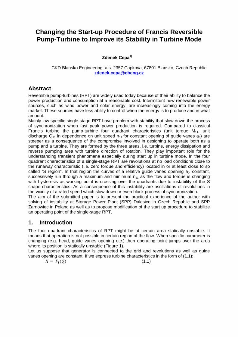
2.2 Modified start-up procedure of SPP Dalesice The behaviour of the single-stage RFT is usually described by a set of characteristics Q11 vs. n11 for flow, and T11 vs. n11 for shaft torque. Except for some step-up curves they are the same for model and prototype see Figure 3.
Fig. 3. Part of measured four-quadrant characteris tics of the model pump-turbine
Turbine Mode I
Q11
Turbine Dissipation II
Reverse Pumping III
T=0 [Nm]
n11

They play important role for understanding and simulation of transient phenomena occurring at the power plants. Sustained oscillations leading to limit cycles could occur for pump-turbines in the S – shaped regions if the stability criterion (1.3) is fulfilled at zero torque (T11=0).
2.2.1 Main technical parameters of SPP Dalesice
Four single-stages RFT are installed at the machine hall having common water intake and four penstocks with inner diameter of 6200 mm and total axis length approximately 319.5 m. Runner diameter 6000mm Range of geodetic heads 59.3m to 90.7m Suction head (max.) -19.28m Maximal discharge in turbine mode 148.3m3.s-1
Maximal output in turbine mode 124.3MW Nominal revolutions 136.36min-1
Penstock factor ∑ ���
�� � � ����.�
��.�� � 10.583�����
2.2.2 Discussion of machine characteristics
Instability of a pump-turbine under no load regime with locked up guide vanes opening can be related to the slope of machine characteristics (see Figure 3) and it is depicted on Figure 4.
Fig. 4. Looking for the pump – turbine region of i nstability with locked GV opening at
a head H = 70m – no load turbine mode Unit speed ��� � �·�
√�� ���.��·�
√��� 97.8 �– � (2.1)
Unit discharge ��� � �
��.√�� ��.��
��·√��� 0.1 �– � (2.2)
Model guide vanes (GV) opening ��� � ��� · ��
�� � 136 · �.���
�.�� 8.1�� (2.3)
Maintaining locked up GV opening; instability can be related to the slopes of discharge-head curves at a runaway and to conduit and machine time constants. Interpolation of machine characteristics is often more revealing in the unit coordinates Q11 - n11. Period of sustained oscillations is about 20s. For a given piping system the instability of the machine can be simply and directly linked to the characteristics of the unit at runaway. The effect of fluid elasticity on the resulting motion and instability can be demonstrated by utilizing the method of characteristic (MOC).
s
0 50 100 150 200 250 300 350 400 450 500 550 600 650 700 750 800 850 900 950 1000 1050 1100
29.55 % 33.87 %
%
125
100
75
50
25
0
kPa
1250
1000
750
500
250
0
kPa
1250
1000
750
500
250
0
Point No. 81 P = 0 MW
Ygv [%] n [%] P [MW] p1 [kPa] p2 [kPa]
29.55 % 33.87 %

Basic values and constants of the particular plant, with respect to analysed non-stationary process, include values that characterize water hammer properties of the penstock and inertia properties of the rotating parts. � Starting time of water in penstock:
This parameter is a measure of the inertia of the mass of water contained in the whole hydraulic system. Is defined as a time TW in which water in penstock of axial length � � ∑ ��
�� � and different cross sections Si reaches from standstill to nominal
speed vi by acting of specific hydraulic energy E or head H
� � ∑ ��·����
���
� �
!·�∑ ��
"� �
� � (2.4)
� Time of water hammer wave reflection:
Defines as a time Tr in which wave due to non-stationary process runs through the penstock of axial length � � ∑ ��
�� � spreading with sound velocity ai from the closing
element up to the upper reservoir with free water level and back
# � 2 · ∑ ��$�
�� � (2.5)
� Unit start up time:
Defined as a time Ta within which unloaded unit starts up from standstill (n=0) and reaches nominal speed n=n0 with acting of constant torque " � �
% , i.e. is determined
by the rate of angular momentum J.ω and torque M
� � &·%
�� &·%�
� (2.6)
2.2.3 Improved control algorithm
The time interval between 845.3 s and 950.4 s was analyzed (see Figure 4). Instantaneous discharge was calculated by MOC from pressure difference ∆p=p1-p2 between reference sections of the penstock G1 and G2 (axial length 168.355m).
Fig. 5. Sustained oscillation for pump-turbine (n 11=97.8 [-], q 11=0.1 [-])
Q = 30.12 m3.s-1, nn = 136.36 min-1

Fig. 6. Dimensionless flow-speed curve showing eff ect of elasticity (time progress
clockwise) After the four-quadrant curves had been updated to reproduce the findings of the no-load tests (see Figure 4), further simulations of the speed control were run by supplier of the turbine and governor. Optimum settings for the no-load parameters of the speed controller resulted from iterative simulations. The final adjustment of the speed controller has been adjusted for head H < 77m, the gain coefficient (proportional constant) Kr = 0.25. Outside of this range the amplification is approximately three times higher i.e. Kr = 0.63. Integration time constant Ti=6s. With such adjustment the synchronization was successful.
2.3 Modified start up procedure of SPP Zarnowiec Based on experience, solving of the instability problem at SPP Dalesice, the first step was modifying of speed control parameters. If the speed set point was at or beyond the hydraulic stability limit, then even the modified turbine governor cannot attain stability. Therefore, in order to ensure stable operation, the hydraulic instability had to be removed. While the low frequency mode of the oscillations is always stabilised, other unstable mode persists in absence of hydraulic stability [5]. They are linked with the natural frequencies of the elastic water column in the penstock.
2.3.1 Main technical parameters of SPP Zarnowiec
Four single-stage Francis reversible pump-turbines are installed at the machine hall having common water intake and four penstocks with inner diameter from 7100mm to 5400mm and total axis length approximately 1150m.
2.3.1.1 Pump-turbine
Runner diameter 6000mm Range of geodetic heads 121m to 101.9m Suction head (max.) -18.72m Maximal discharge in turbine mode 178.5m3.s-1
Maximal output in turbine mode 193MW Nominal revolutions 166.7min-1
Penstock factor ∑ ���
�� � � 36.15934�����
2.3.1.2 Butterfly valve
Upstream of the pump-turbine is installed biplane butterfly valve (BV), having vertical axis. Pressure oil is supplied from high pressure unit (HPU) to two opposite coupled servomotors. Inner diameter 5400mm Number of horizontal coupled servomotors 2
2.3.2 Operating point stability at no load regime
For the benefit of stability, operating point under the lower head conditions Hg<113m (n11>94.1), an artificial head loss was added at the lower end of the penstock by means of partial opened BV. The turbine start as well as synchronization is performed with the BV in a partial open position (32%), which was determined by simulations and optimised by a series of field tests. Only after synchronization the BV is fully opened and at the same time the Unit takes up load with the foreseen ramp. The structure and parameter setting of the speed governor could be retained. For the purpose of the paper briefness only final results and adjustment is discussed here. The detail discussion and test results as well as modification of BV control and complete hydraulic scheme is possible to find out in [8]. Because of the new utilization of the BV is partly different from one described in the technical specifications, it was necessary to verify the implementation of the new method by a series of field tests [8]. � Start up tests with different BV partial opening (throttling);
� Speed control tests with different BV partial opening;
� Tests of automatic start up sequence;
� Synchronization tests;
� Loading of the unit for foreseen ramp;
During these tests [8] the pump-turbine and BV was equipped with additional sensors to measure selected vibrations and pressure pulsations influenced by the partially throttling. Particular attention was paid to the following parameters: � Relative shaft vibrations in turbine guide bearing (Xr, Yr);
� Absolute vibrations of BV upper bearing housing Xa_bv_bear;
� Absolute vibrations of BV support basement Xa_bv_base;
� Absolute axial vibrations of the upper turbine cover Za;
� Pressure in the penstock p1, spiral casing throat p2, vane less space p3 and draft tube p4;
� Parameters from the control system to specify operational point;
2.3.3 Results of the tests
All the modifications were realised and tested within two days. Modification of the HPU concerning BV control was done by the customer in advance as required in [8]. In order to compare directly benefit of performed modification let us discussed the worst case of synchronizing close to a minimal head.
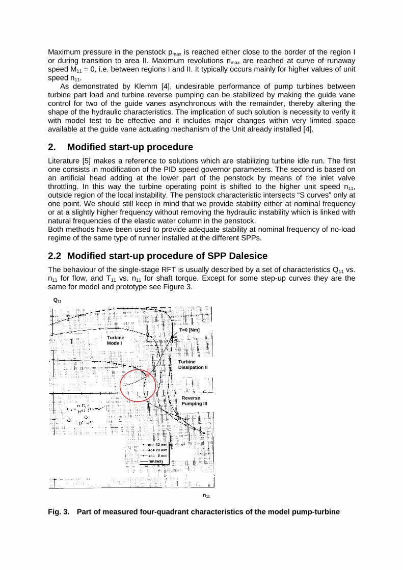
2.3.3.1 Automatic start up without modification of BV automatics Test No. z1 z2 Hg Ybv Ygv Q p1 p2 ∆Hbv
[-] [m asl.] [m asl.] [m] [%] [%] [m3.s-1] [kPa] [kPa] [m]
17 110.9 1.78 109.12 100 32 30.65 1235.3 1227.7 R0.70
Tab. 1 Main parameters of test No. 17
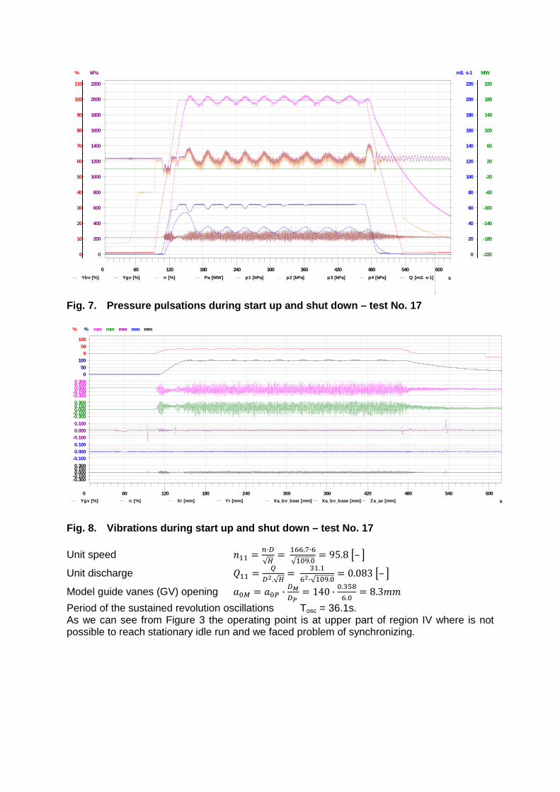
Fig. 7. Pressure pulsations during start up and sh ut down – test No. 17
Fig. 8. Vibrations during start up and shut down – test No. 17 Unit speed ��� � �·�
√�� ���.�·�
√���.�� 95.8 �– �
Unit discharge ��� � �
��.√�� ��.�
��·√���.�� 0.083 �– �
Model guide vanes (GV) opening ��� � ��� · ��
�� � 140 · �.���
�.�� 8.3��
Period of the sustained revolution oscillations Tosc = 36.1s. As we can see from Figure 3 the operating point is at upper part of region IV where is not possible to reach stationary idle run and we faced problem of synchronizing.
s
0 60 120 180 240 300 360 420 480 540 600
%
110
100
90
80
70
60
50
40
30
20
10
0
MW
220
180
140
100
60
20
-20
-60
-100
-140
-180
-220
kPa
2200
2000
1800
1600
1400
1200
1000
800
600
400
200
0
m3. s-1
220
200
180
160
140
120
100
80
60
40
20
0
Ybv [%] Ygv [%] n [%] Pa [MW] p1 [kPa] p2 [kPa] p3 [kPa] p4 [kPa] Q [m3. s-1]
s
0 60 120 180 240 300 360 420 480 540 600
%
100500
%
100500
mm
0.3000.1500.000
-0.150-0.300
mm
0.3000.1500.000
-0.150-0.300
mm
0.1000.000
-0.100
mm
0.1000.000
-0.100
mm
0.3000.1500.000
-0.150-0.300
Ygv [%] n [%] Xr [mm] Yr [mm] Xa_bv_bear [mm] Xa_bv_base [mm] Za_ax [mm]

2.3.3.2 Stabilising effect of the butterfly valve h ead loss
The tests No. 12 through 16 [8] were repeated with several different constant opening of BV positions in the range of ybv = 28.7% to 35.7%. At ybv < 32% the throttling effect was good enough to stabilise operating point but not enough to reach nominal speed. Test No. z1 z2 Hg Ybv Ygv Q p1 p2 ∆Hbv
[-] [m asl.] [m asl.] [m] [%] [%] [m3.s-1] [kPa] [kPa] [m]
16 110.9 1.78 109.12 32.5 34.7 37.3 1237.7 1139.6 R8.21
Tab. 2 Main parameters of test No. 16
Unit speed ��� � �·�
√�� ���.�·�
√��.��� 100.14 �– �
Unit discharge ��� � �
��.√�� ��.�
��·√��.��� 0.103 �– �
Model guide vanes (GV) opening ��� � ��� · ��
�� � 157 · �.���
�.�� 9.4��
Fig. 9. Pressure pulsations during modified start up sequence – Test No. 16
Fig. 10. Detail of start up, synchronizing and loa ding – test No. 16
s
0 60 120 180 240 300 360 420 480 540 600
%
110
100
90
80
70
60
50
40
30
20
10
0
MW
220
180
140
100
60
20
-20
-60
-100
-140
-180
-220
kPa
2200
2000
1800
1600
1400
1200
1000
800
600
400
200
0
m3. s-1
220
200
180
160
140
120
100
80
60
40
20
0
Ybv [%] Ygv [%] n [%] Pa [MW] p1 [kPa] p2 [kPa] p3 [kPa] p4 [kPa] Q [m3. s-1]
s
10 20 30 40 50 60 70 80 90 100 110 120 130 140 150 160 170 180 190 200 210 220 230 240 250
%
110
100
90
80
70
60
50
40
30
20
10
0
MW
220
180
140
100
60
20
-20
-60
-100
-140
-180
-220
kPa
2200
2000
1800
1600
1400
1200
1000
800
600
400
200
0
m3. s-1
220
200
180
160
140
120
100
80
60
40
20
0
Ybv [%] Ygv [%] n [%] Pa [MW] p1 [kPa] p2 [kPa] p3 [kPa] p4 [kPa] Q [m3. s-1]

Fig. 11. Vibrations during modified start up seque nce – test No. 16 The amount of throttling required, about 186kPa close to nominal speed in the most extreme transient case, is a quite acceptable fraction of a rated head. At ybv=32.5% opening the throttling effect was good enough to stabilize the whole range of operating speed but not too strong with regard to pressure pulsations and BV housing vibrations.
3. Conclusions The theory, which was developed principally to illustrate which machine characteristics affect instability, was based upon frictionless flow and rigid water column. Limited elastic analysis indicated that, for certain ratios of the elastic to machine constants, water hammer may be neglected; whereas, for larger ratios fluid elasticity must be considered [2]. The aim of the tests was focused on hydraulic stability of the unit. Two solutions were discussed. The first one consists in modifying of the digital turbine speed governor but it turned out to be insufficient in the case of SPP Zarnowiec. The second solution proved to be simpler and effective to realize. An artificial head loss was added at the lower part of the penstock by means of the BV throttling during start-up of the Unit. BV throttling is hydraulically quite effective to push the stability limit toward higher n11 and is mechanically quite acceptable. This modification has been realized on all four Units, tested and after specific tests had proved that the modified procedure does not entail any mechanical drawback.
s
0 60 120 180 240 300 360 420 480 540 600
%
100500
%
100500
mm
0.3000.1500.000
-0.150-0.300
mm
0.3000.1500.000
-0.150-0.300
mm
0.1000.000
-0.100
mm
0.1000.000
-0.100
mm
0.3000.1500.000
-0.150-0.300
Ygv [%] n [%] Xr [mm] Yr [mm] Xa_bv_bear [mm] Xa_bv_base [mm] Za_ax [mm]

References [1] Sob, F., Pulpitel, L.: Problems of emergency shutdown related to Francis reversible
turbines. In: Paper E7 of HYDROTURBO 81 conference.
[2] Martin, C. S.: Effect of pump-turbine characteristics near runaway on instability.
[3] Martin, C. S.: Stability of pump-turbines during transient operation. In: 5th International Conference on Pressure Surge, Hannover, September 1986.
[4] Klemm, D.: Stabilising of the characteristics of a pump-turbine in the range between turbine part-load and reverse pumping operation. In: Voith Forschung und Konstruction, Vol. 28, 1982.
[5] Dorfler, P. K. at al.: Stable operation achieved on a single-stage reversible pump-turbine showing instability at no-load. In; XIX Symposium of IAHR Section on Hydro Machinery and Cavitation, Singapore 1998.
[6] Staubli, T. et al.: Instability of pump-turbines during start-up in turbine mode.
[7] Cepa, Z.: Report on commissioning after rehabilitation and runner replacement, SPP Dalesice Unit No. 1 in Czech Republic. In: Report of CBE No: 2001-60-006-0486, September 2001.
[8] Cepa, Z.: Report on stabilizing of the characteristics of a pump-turbine in the range between turbine part load and reverse pumping operation, SPP Zarnowiec Unit No. 2 in Poland. In: Report of CBE No. 2006-60-006-0683, September 2006.
Author 1) Zdenek Cepa: Received his Ph.D. degree in 1992 from Czech University of Science and Technology in Brno in the field of Non-destructive diagnostics. When graduated in 1978 he headed the Hydraulic Laboratory in CKD Blansko. Currently he is a Head of Department of the Hydraulic Machinery Tests and Diagnostics in CKD Blansko Engineering (Litostroj Power). He is a member of Czech National Committee IEC TC 4-Water turbines and International Maintenance Team (MT28) for Innovations of discharge method calculations. Main professional interests: Hydraulic transients in closed conduits (discharge calculations, analysis), flow rate measurements in open channels, problems of hydraulic machinery design and operation, experimental modal analysis.


![Francis Turbine [Compatibility Mode]](https://img.pdfslide.net/doc/110x75/55cf92f8550346f57b9ab6be/francis-turbine-compatibility-mode.jpg)