Embed Size (px)
Citation preview
Page 1
123809
Changing the way you work, connected alignments and dynamic offset profiles Ian Philpott Ramboll
Description
AutoCAD Civil3D 2018 introduced a raft of new features. This class looks at two of those new features, Connected Alignments and Dynamic Offset Profiles and how they will change the way you work with Civil3D. We will also look at some innovative ways to use these new features for other things, not just junctions. Who needs the junction wizard anymore? This workflow gives you more control and versatility. Speaker(s)
Ian Philpott is a Technical Associate in the Transport Group of Ramboll UK. Ian has over 20 years’ experience working for both consultants and contractors in a wide variety of roles from design, 3D modelling, co-ordination and BIM process implementation. Civil3D has been Ian's core software platform since 2010, he has supported many users over the last 7 years, presented classes at AU 2014 & 2015 and been involved with Inside the Factory events. Ian's current role is a technical expert providing support to highways and infrastructure teams across the U.K, upskilling those teams with digital engineering skills across many platforms and project complexities including Civil3D, Navisworks and BIM workflows.
Learning Objectives
Understand the capabilities of connected alignments and dynamic offset profiles How this new functionality can be incorporated in to daily workflows Understand the limitations of the new functions Tips and tricks to use the new functions for not just road corridors
Page 2
Introduction
This class looks at two new tools, Connected Alignments and Dynamic Offset Profiles that became available in the 2018 version of Civil3D. We will look at capabilities, limitations and workflows for these new tools before going on to look at some innovative uses aside from standard road corridor creation Dynamic Offset Profiles
Civil3D gained dynamic offset alignments in 2010. 2018 sees the profiles associated with those alignments gain a dynamic relationship to the profile of the parent alignment they were offset from.
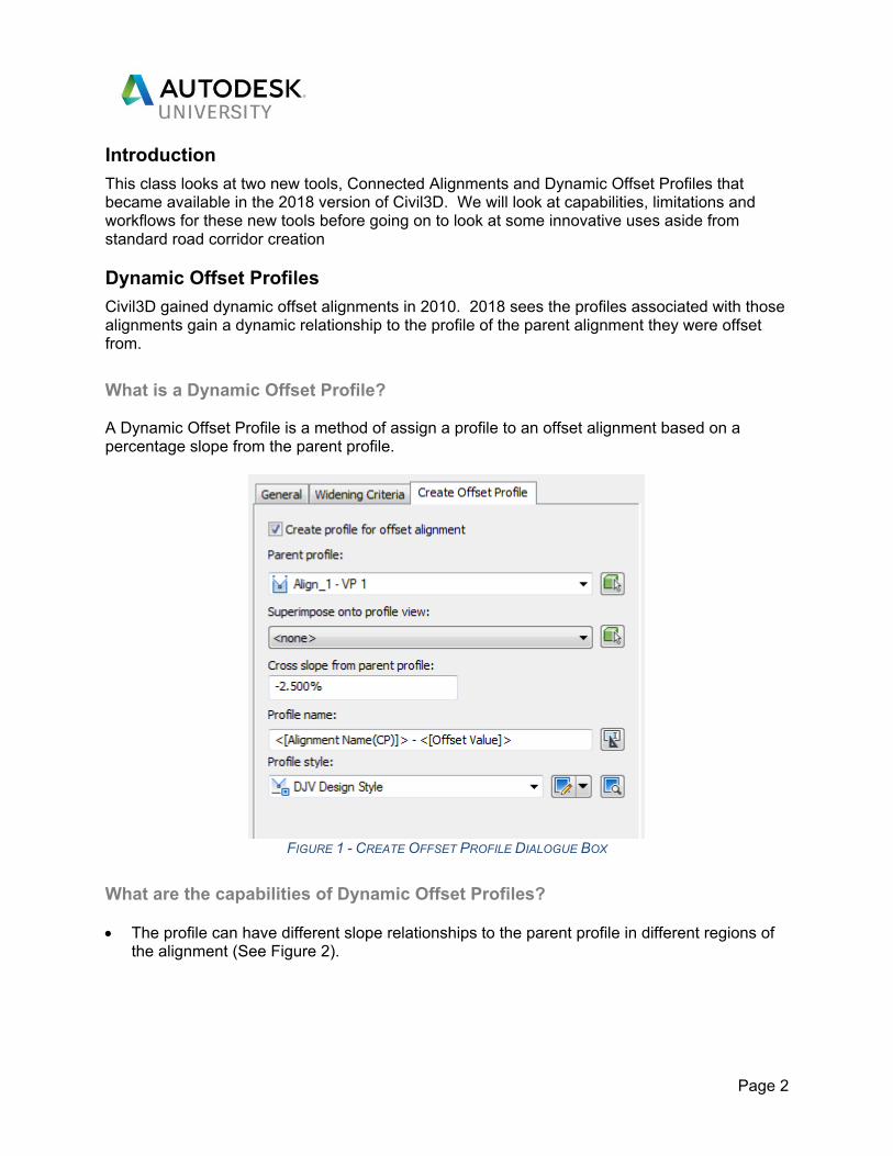
What is a Dynamic Offset Profile? A Dynamic Offset Profile is a method of assign a profile to an offset alignment based on a percentage slope from the parent profile.
FIGURE 1 - CREATE OFFSET PROFILE DIALOGUE BOX
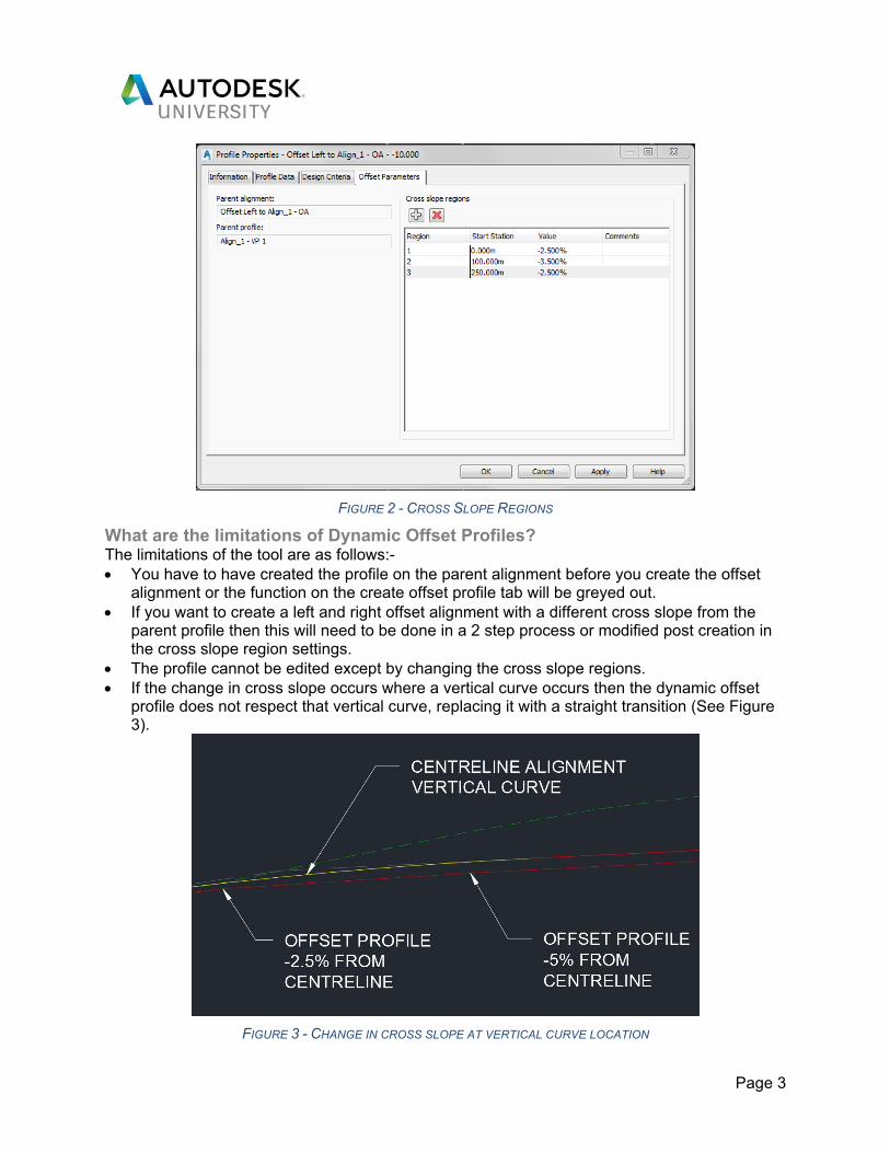
What are the capabilities of Dynamic Offset Profiles? The profile can have different slope relationships to the parent profile in different regions of
the alignment (See Figure 2).
Page 3
FIGURE 2 - CROSS SLOPE REGIONS
What are the limitations of Dynamic Offset Profiles? The limitations of the tool are as follows:- You have to have created the profile on the parent alignment before you create the offset
alignment or the function on the create offset profile tab will be greyed out. If you want to create a left and right offset alignment with a different cross slope from the
parent profile then this will need to be done in a 2 step process or modified post creation in the cross slope region settings.
The profile cannot be edited except by changing the cross slope regions. If the change in cross slope occurs where a vertical curve occurs then the dynamic offset
profile does not respect that vertical curve, replacing it with a straight transition (See Figure 3).
FIGURE 3 - CHANGE IN CROSS SLOPE AT VERTICAL CURVE LOCATION
Page 4
Connected Alignments
When two alignments intersect for example where a junction kerb return is formed it has, until now, not been possible to maintain the relationship when changes are made. In 2018 Connected Alignments gave the user that control.
What is a Connected Alignments? It’s a dynamic alignment that connects two alignments both horizontally and vertically. If you are familiar with the intersections (junctions) wizard you will see that this new tool behaves in a similar way except it has taken those capabilities from within the intersection wizard and exposed them as individual tools, making them simpler and more adaptable to different situations. They can be used in any situation where you want to maintain a tangential single curved arrangement between two alignments.
What are the capabilities of Connected Alignments? The capabilities of the tool are as follows:-
Provides a single radius fillet between two intersecting alignments Creates a dynamic but editable profile based on the profiles of the two connecting
alignments User specified connection overlap
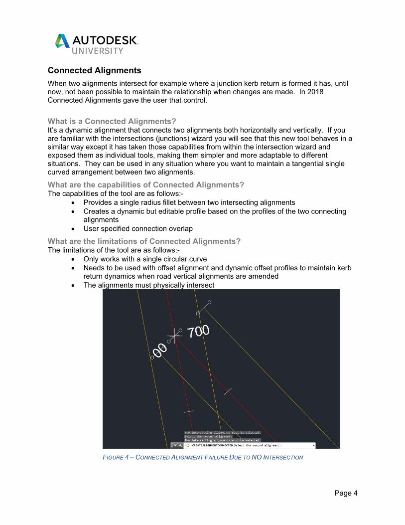
What are the limitations of Connected Alignments? The limitations of the tool are as follows:-
Only works with a single circular curve Needs to be used with offset alignment and dynamic offset profiles to maintain kerb
return dynamics when road vertical alignments are amended The alignments must physically intersect
FIGURE 4 – CONNECTED ALIGNMENT FAILURE DUE TO NO INTERSECTION
Page 5
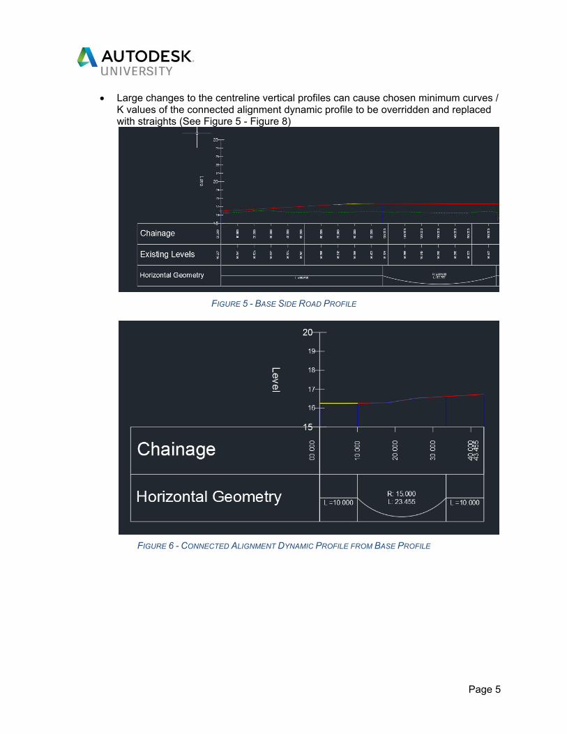
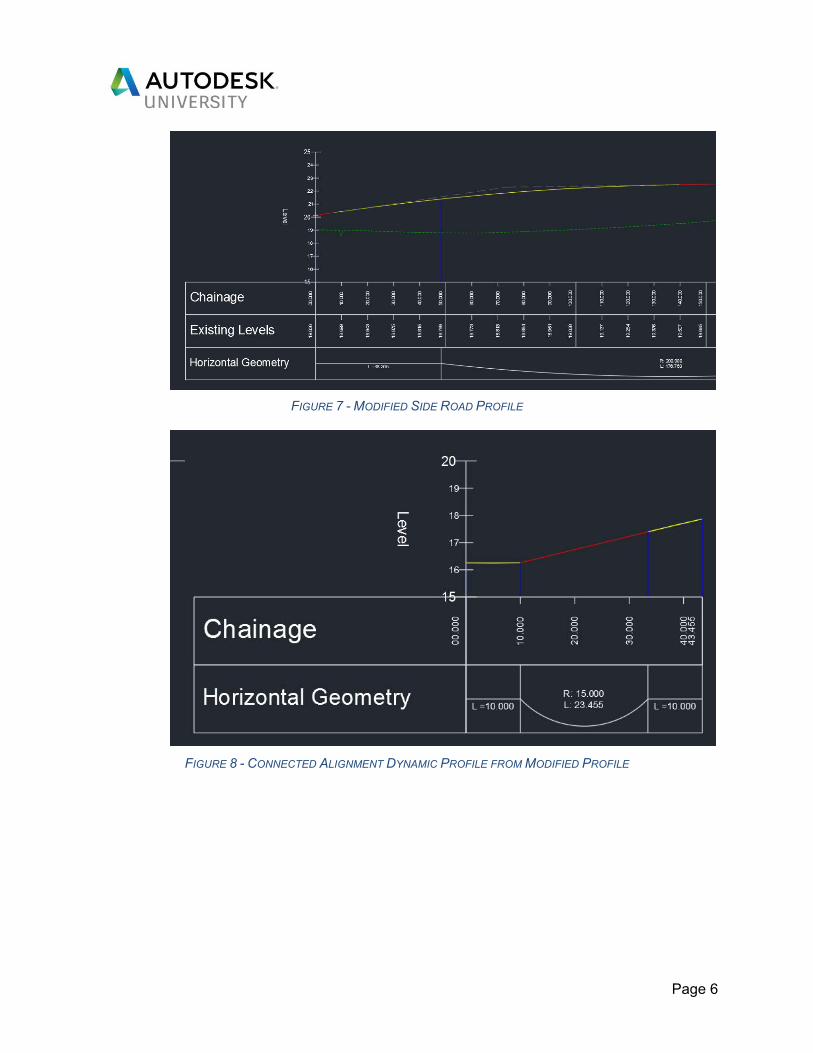
Large changes to the centreline vertical profiles can cause chosen minimum curves / K values of the connected alignment dynamic profile to be overridden and replaced with straights (See Figure 5 - Figure 8)
FIGURE 5 - BASE SIDE ROAD PROFILE
FIGURE 6 - CONNECTED ALIGNMENT DYNAMIC PROFILE FROM BASE PROFILE
Page 6
FIGURE 7 - MODIFIED SIDE ROAD PROFILE
FIGURE 8 - CONNECTED ALIGNMENT DYNAMIC PROFILE FROM MODIFIED PROFILE
Page 7
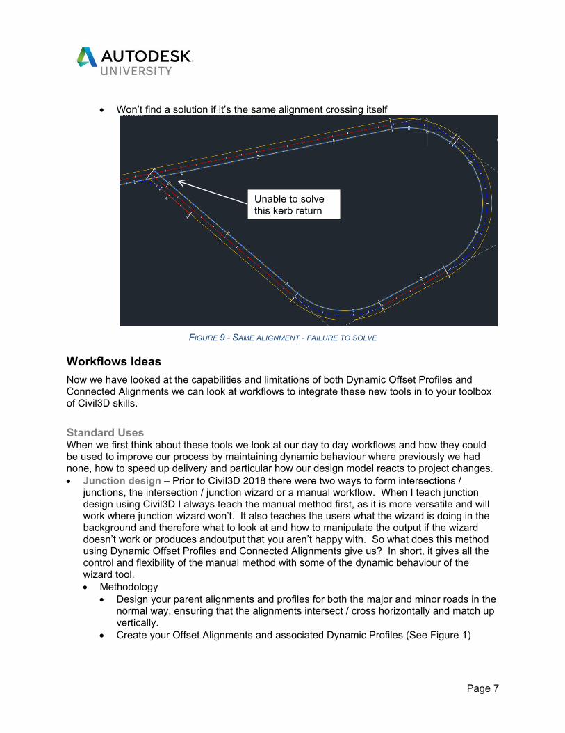
Won’t find a solution if it’s the same alignment crossing itself
FIGURE 9 - SAME ALIGNMENT - FAILURE TO SOLVE Workflows Ideas
Now we have looked at the capabilities and limitations of both Dynamic Offset Profiles and Connected Alignments we can look at workflows to integrate these new tools in to your toolbox of Civil3D skills.
Standard Uses When we first think about these tools we look at our day to day workflows and how they could be used to improve our process by maintaining dynamic behaviour where previously we had none, how to speed up delivery and particular how our design model reacts to project changes. Junction design – Prior to Civil3D 2018 there were two ways to form intersections /
junctions, the intersection / junction wizard or a manual workflow. When I teach junction design using Civil3D I always teach the manual method first, as it is more versatile and will work where junction wizard won’t. It also teaches the users what the wizard is doing in the background and therefore what to look at and how to manipulate the output if the wizard doesn’t work or produces andoutput that you aren’t happy with. So what does this method using Dynamic Offset Profiles and Connected Alignments give us? In short, it gives all the control and flexibility of the manual method with some of the dynamic behaviour of the wizard tool. Methodology
Design your parent alignments and profiles for both the major and minor roads in the normal way, ensuring that the alignments intersect / cross horizontally and match up vertically.
Create your Offset Alignments and associated Dynamic Profiles (See Figure 1)
Unable to solve this kerb return
Page 8
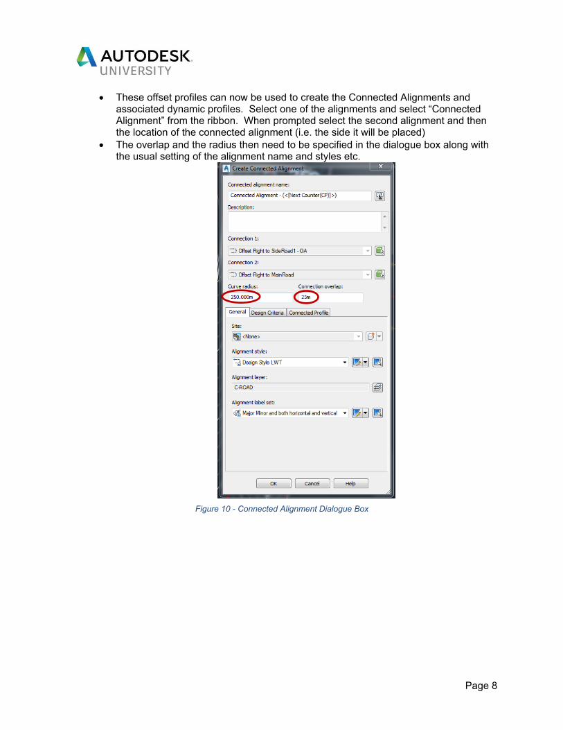
These offset profiles can now be used to create the Connected Alignments and associated dynamic profiles. Select one of the alignments and select “Connected Alignment” from the ribbon. When prompted select the second alignment and then the location of the connected alignment (i.e. the side it will be placed)
The overlap and the radius then need to be specified in the dialogue box along with the usual setting of the alignment name and styles etc.
Figure 10 - Connected Alignment Dialogue Box
Page 9
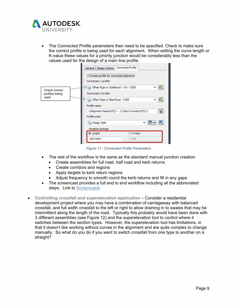
The Connected Profile parameters then need to be specified. Check to make sure
the correct profile is being used for each alignment. When setting the curve length or K-value these values for a priority junction would be considerably less than the values used for the design of a main line profile.
Figure 11 - Connected Profile Parameters
The rest of the workflow is the same as the standard manual junction creation Create assemblies for full road, half road and kerb returns Create corridors and regions Apply targets to kerb return regions Adjust frequency to smooth round the kerb returns and fill in any gaps
The screencast provides a full end to end workflow including all the abbreviated steps. Link to Screencasts
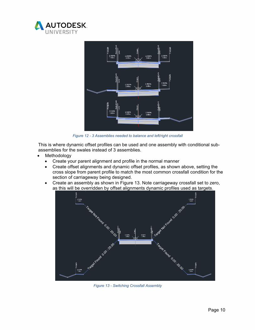
Controlling crossfall and superelevation application – Consider a residential
development project where you may have a combination of carriageway with balanced crossfall, and full width crossfall to the left or right to allow draining in to swales that may be intermittent along the length of the road. Typically this probably would have been done with 3 different assemblies (see Figure 12) and the superelevation tool to control where it switches between the section types. However, the superelevation tool has limitations, in that it doesn’t like working without curves in the alignment and are quite complex to change manually. So what do you do if you want to switch crossfall from one type to another on a straight?
Check correct profiles being used
Page 10
Figure 12 - 3 Assemblies needed to balance and left/right crossfall
This is where dynamic offset profiles can be used and one assembly with conditional sub-assemblies for the swales instead of 3 assemblies. Methodology
Create your parent alignment and profile in the normal manner Create offset alignments and dynamic offset profiles, as shown above, setting the
cross slope from parent profile to match the most common crossfall condition for the section of carriageway being designed.
Create an assembly as shown in Figure 13. Note carriageway crossfall set to zero, as this will be overridden by offset alignments dynamic profiles used as targets.
Figure 13 - Switching Crossfall Assembly
Page 11
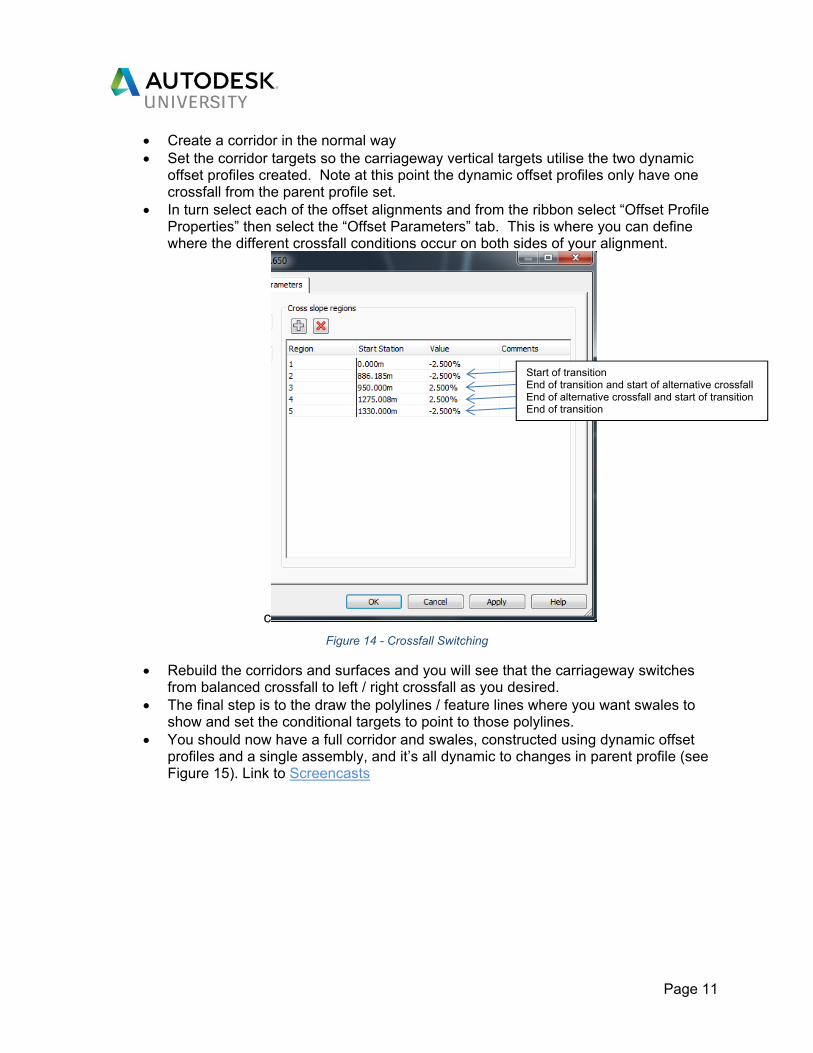
Create a corridor in the normal way Set the corridor targets so the carriageway vertical targets utilise the two dynamic
offset profiles created. Note at this point the dynamic offset profiles only have one crossfall from the parent profile set.
In turn select each of the offset alignments and from the ribbon select “Offset Profile Properties” then select the “Offset Parameters” tab. This is where you can define where the different crossfall conditions occur on both sides of your alignment.
c
Figure 14 - Crossfall Switching
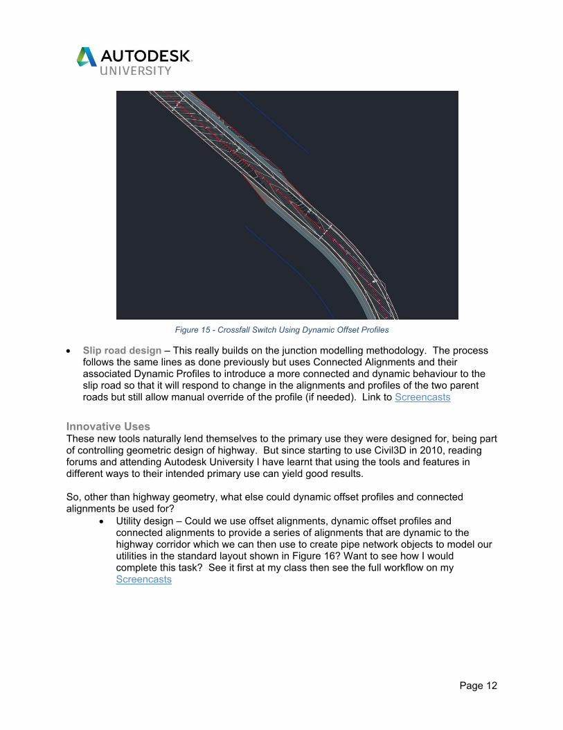
Rebuild the corridors and surfaces and you will see that the carriageway switches from balanced crossfall to left / right crossfall as you desired.
The final step is to the draw the polylines / feature lines where you want swales to show and set the conditional targets to point to those polylines.
You should now have a full corridor and swales, constructed using dynamic offset profiles and a single assembly, and it’s all dynamic to changes in parent profile (see Figure 15). Link to Screencasts
Start of transition End of transition and start of alternative crossfall End of alternative crossfall and start of transition End of transition
Page 12
Figure 15 - Crossfall Switch Using Dynamic Offset Profiles
Slip road design – This really builds on the junction modelling methodology. The process follows the same lines as done previously but uses Connected Alignments and their associated Dynamic Profiles to introduce a more connected and dynamic behaviour to the slip road so that it will respond to change in the alignments and profiles of the two parent roads but still allow manual override of the profile (if needed). Link to Screencasts
Innovative Uses These new tools naturally lend themselves to the primary use they were designed for, being part of controlling geometric design of highway. But since starting to use Civil3D in 2010, reading forums and attending Autodesk University I have learnt that using the tools and features in different ways to their intended primary use can yield good results. So, other than highway geometry, what else could dynamic offset profiles and connected alignments be used for?
Utility design – Could we use offset alignments, dynamic offset profiles and connected alignments to provide a series of alignments that are dynamic to the highway corridor which we can then use to create pipe network objects to model our utilities in the standard layout shown in Figure 16? Want to see how I would complete this task? See it first at my class then see the full workflow on my Screencasts

Page 13
Figure 16 - Extract of NJUG guidelines for utility installation in the UK (NJUG, 2003)
SUDS and flood protection – Sustainable Urban Drainage (SUDS) and flood protection measures are now an integral part of our design process for developments. Consider a development project where some of the land is known to flood in extreme storm events. Your client wants to build a development on part of the land because it’s adjacent to their current facility. They accept the flood potential will need to be managed and has set aside some of the land for flood mitigation but would like a landscape that provides amenity space for the employees but also helps mitigate the flood potential. Your team has a concept idea but it needs to be modelled in 3D to determine the additional flood storage that has been created and to show the client what amenity value can be gained from this area. You are sure there is a solution in there but you know it will need some iterations and changes before it works technically, tweaks to help balance earthworks volumes and further changes before the client signs off on the amenity benefits. Therefore you want a dynamic model that all moves with any changes and minimises rework.

Page 14
How do you model it??? Feature lines? Quick to create a basic model and easy to tweak but relationship
between different elements are not dynamic. Modeller has to remember how the relationships work and adjust the values to suit
Feature lines and grading groups? Adding grading provides some parametric and dynamic behaviour but you are worried about the stability of the model when needing to make multiple changes and having to delete grading to make a change before reapplying the grading
Alignments and corridors? Might be a solution but finishing off little areas where channels end or merge is a manual process.
Civil3D 2018 has lots of new dynamic behaviour, Dynamic Offset Alignments and
Connected Alignments we have focused on in this class. There are also relative feature lines that could be very useful. Want to see how I would complete this task? See it first at my class then see the full workflow on my Screencasts
Page 15
References and Useful Information
Screencasts All of the workflows outlined above have been captured using Autodesk Screencast. These along with any others used in my presentation at AU 2017 will be made available post the presentation (got to keep my tips and tricks to show those who turn up to my class first) – Until then the links below take you to my other Screencast Videos) Junction Design Using Connected Alignments Controlling Crossfall and Superelevation Application Slip Road Design Using Connected Alignments Utility Design Using Dynamic Offset Profiles and Connected Alignments SUDS and Flood Protection
Useful Web Resources There are lots of useful on these new features. Below are some of my favourite online resources. Connected Alignments on Autodesk Knowledge Network Connected Alignments on Cadline Community What's new in Civil3D 2018 on Civil3D Plus Offset Profiles and Connected Alignments on Civil Immersion Blog Dynamic Offset Profiles on Autodesk Knowledge Network Dynamic Offset Profiles Civil 3D 2018 New Feature: Offset Profiles & Connected Alignments - Pt. 1 - By Jeff Bartels Civil 3D 2018 New Feature: Offset Profiles & Connected Alignments - Pt. 2 - By Jeff Bartels Contact
Email: [email protected] Twitter: @Ian_Philpott