Embed Size (px)
Citation preview
Channel Bonding in DOCSIS 3.0Channel Bonding in DOCSIS 3.0
Greg WhiteLead Architect – Broadband AccessCableLabs
2
AgendaAgenda
DS Channel Bonding Protocol• Receive Channel Profiles• US Channel Bonding Protocol• HFC Plant Topologies & Resolution
3
DS Channel Bonding ProtocolDS Channel Bonding Protocol
• Packet-based Bonding• DSIDs
DS Service Extended-Header formats
• ResequencingNetwork SkewResequencing ContextsRapid Loss Detection
• DSIDs and Service Flows• Communicating DSIDs
4
Packet-based BondingPacket-based Bonding
• Entire MAC layer packets are transmitted intact on a selected downstream channel
• CMTS distributes the packets dynamically across the channels in the bonding group
• To ensure in-order delivery, CMTS labels each packet and attaches a sequence number.
CM must re-sequence the packets before forwarding
5
Downstream Service IDs (DSIDs)Downstream Service IDs (DSIDs)
• The 20-bit label used to identify all of the packets in a “resequencing context”.
• Within a resequencing context, packets are numbered sequentially.
• DSIDs are also used to label multicast trafficIn this case they may (or may not) also be used for resequencing.
6
DS EHDR FormatsDS EHDR Formats
• New Extended Header (EHDR) in the DOCSIS MAC-Layer Frame header
• Three formats defined“1-Byte” to carry Traffic Priority tag– Layer 2 priority tagging for non-bonded unicast traffic
“3-Byte” to carry Traffic Priority & DSID– DSID labeling for non-bonded multicast traffic
“5-Byte” to carry Traffic Priority, DSID & Seq. Number– DSID label & Seq. Number for bonded traffic
7
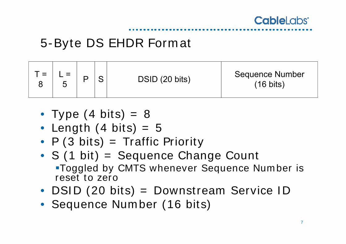
5-Byte DS EHDR Format5-Byte DS EHDR Format
• Type (4 bits) = 8• Length (4 bits) = 5• P (3 bits) = Traffic Priority• S (1 bit) = Sequence Change Count
Toggled by CMTS whenever Sequence Number is reset to zero
• DSID (20 bits) = Downstream Service ID• Sequence Number (16 bits)
8
Resequencing – Network SkewResequencing – Network Skew
• Downstream Channels may not all have the same amount of latency due to:
Internal CMTS processing latency differencesJ.83 Interleaving latency differencesM-CMTS network paths
• The result is that two packets scheduled simultaneously by the CMTS may not arrive simultaneously at the CM
• Packets may get out of sequence• Worst case network skew allowed: 18ms
9
Resequencing ContextsResequencing Contexts
• To return packets to proper order, CM must support resequencing based on DSID and Seq.Number.
• CM must support at least 16 independent resequencing contexts (i.e. 16 DSIDs for resequencing).
• The CM will hold higher numbered packets until all lower numbered packets have arrived
CM MUST support a default 18ms “Resequencing Wait” per DSID (can be configured for less)CM MUST support “rapid loss detection”
10
Rapid Loss Detection ExampleRapid Loss Detection Example
• CM is receiving traffic on 4 channels for a DSID• Packet number X has not been received• Once CM receives a packet with a higher
number than X on all four channels, it can declare X as lost and release buffer contents
11
DSIDs and Service FlowsDSIDs and Service Flows
• In DOCSIS 1.1 & 2.0 a SID and an Upstream Service Flow have a 1:1 correspondence
• The same is NOT true of DSIDs and Downstream Service Flows
Many DS Service Flows can share a single DSIDIn certain cases, multiple DSIDs could be used to label packets for a particular DS Service Flow
• For bonding, the DSID identifies a resequencing context and an associated set of Downstream Channels.
12
Communicating DSIDs (CMTS -> CM)Communicating DSIDs (CMTS -> CM)
• The CMTS needs to inform each CM of the DSIDs that will be used for bonded traffic to that CM
• There are two mechanisms:Registration (REG-RSP)Dynamic Bonding Change (DBC-REQ)
13
Dynamic Bonding ChangeDynamic Bonding Change
• Replacement for DCC in DOCSIS 3.0• Handles:
Receive Channel Set (RCS) changes– Channels received by the CM
Transmit Channel Set (TCS) changes– Channels CM can transmit on
Changes to DSIDs (additions, changes, deletions)– Add/delete DSID for bonded service flows– Add/delete DSID for multicast forwarding– Changes to “Resequencing Channel List” for a DSID– Etc.
14
AgendaAgenda
• DS Channel Bonding ProtocolReceive Channel Profiles
• US Channel Bonding Protocol• HFC Plant Topologies & Resolution
15
Receive Channel ProfilesReceive Channel Profiles
• CM vendors wanted maximum flexibility in designing new CM receiver architectures
• CMTS vendors didn’t want to have to handle arbitrary complexity in CM receiver architectures
• To minimize the complexity in the CMTS, and still allow for CM innovation, the concept of Receive Channel Profiles was created
16
Receive Channel Profiles (cont.)Receive Channel Profiles (cont.)
• Components:A syntax for describing the CM receiver architectureA system to define “standard RCPs”Flexibility for vendors to define “vendor specific RCPs”
• CMTS can choose for CMs to:Only send RCP-IDs Send verbose RCP encodings
• Allows CMTS vendors flexibility to support new CMs in various ways
• CMTS also uses RCP encodings to configure which receiver in the CM is tuned to which downstream channel
Termed a Receive Channel Configuration (RCC)
17
RCP SyntaxRCP Syntax
• RCP-ID• RCP Name• Frequency Spacing (6MHz or 8MHz)• Set of zero or more Receive Modules
Bandwidth (# adjacent channels)Frequency placement limitationsBonding limitationsParameter independence (QAM, Interleave)
• Set of one or more Receive Channels
18
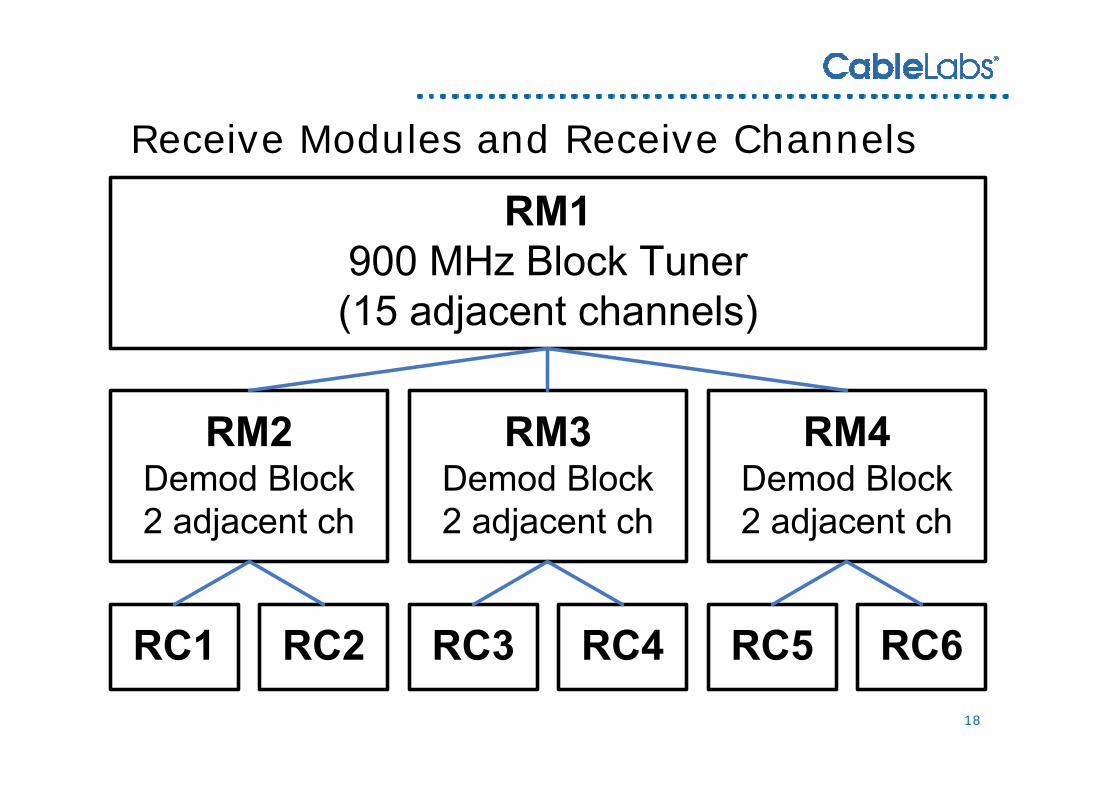
Receive Modules and Receive ChannelsReceive Modules and Receive Channels
19
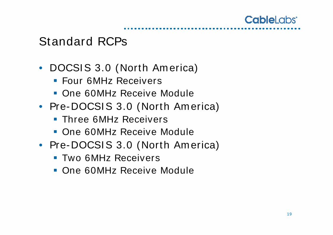
Standard RCPsStandard RCPs
• DOCSIS 3.0 (North America)Four 6MHz ReceiversOne 60MHz Receive Module
• Pre-DOCSIS 3.0 (North America)Three 6MHz ReceiversOne 60MHz Receive Module
• Pre-DOCSIS 3.0 (North America)Two 6MHz ReceiversOne 60MHz Receive Module
20
AgendaAgenda
• DS Channel Bonding Protocol• Receive Channel Profiles
US Channel Bonding Protocol• HFC Plant Topologies & Resolution
21
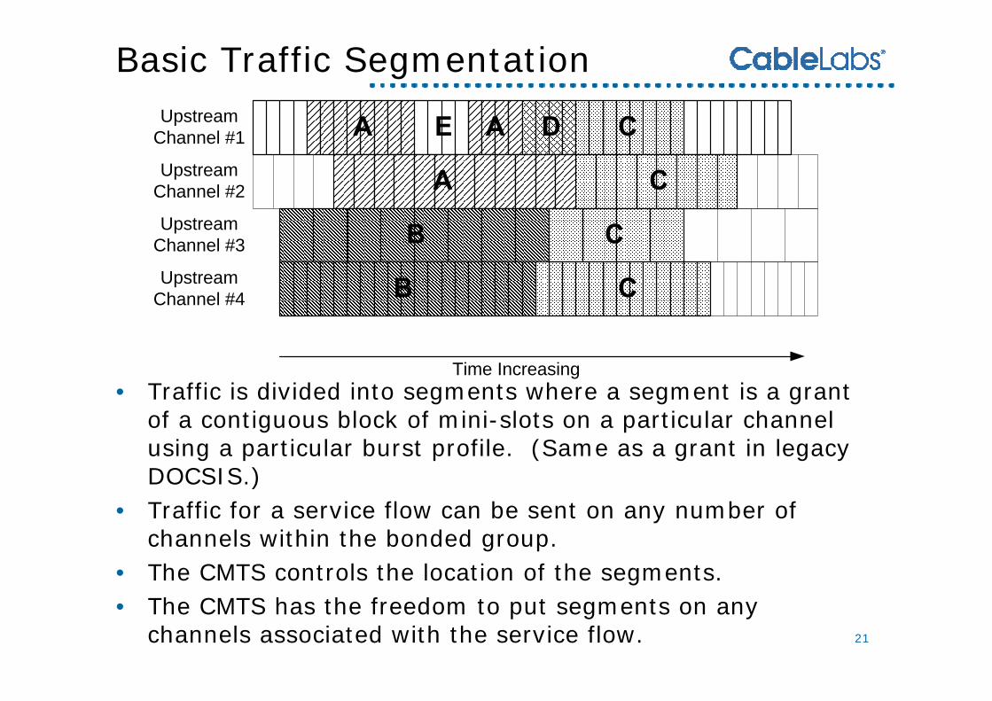
Basic Traffic SegmentationBasic Traffic Segmentation
• Traffic is divided into segments where a segment is a grant of a contiguous block of mini-slots on a particular channel using a particular burst profile. (Same as a grant in legacy DOCSIS.)
• Traffic for a service flow can be sent on any number of channels within the bonded group.
• The CMTS controls the location of the segments.• The CMTS has the freedom to put segments on any
channels associated with the service flow.
Upstream Channel #1
Upstream Channel #2
Upstream Channel #3
Upstream Channel #4
Time Increasing
22
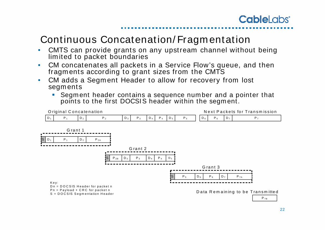
Continuous Concatenation/FragmentationContinuous Concatenation/Fragmentation• CMTS can provide grants on any upstream channel without being
limited to packet boundaries • CM concatenates all packets in a Service Flow’s queue, and then
fragments according to grant sizes from the CMTS• CM adds a Segment Header to allow for recovery from lost
segmentsSegment header contains a sequence number and a pointer that points to the first DOCSIS header within the segment.
G ra n t 2
G ra n t 3
D 1 P 1 D 2 P 2 D 3 P 3 D 4 P 4 D 5 P 5 D 6 P 6
D 1 P 1 D 2
P 2 B D 3 P 3 D 4 P 4
P 5
D 7 P 7
P 2 A
S
S
D 5
S D 6 P 6 D 7 P 7 A
P 7 B
O r ig in a l C o n c a te n a tio n N e x t P a c k e ts fo r T ra n s m is s io n
D a ta R e m a in in g to b e T ra n s m itte d
G ra n t 1
K e y :D n = D O C S IS H e a d e r fo r p a c k e t nP n = P a y lo a d + C R C fo r p a c k e t nS = D O C S IS S e g m e n ta tio n H e a d e r
23
Multiple Transmit Channel Mode Request MechanismMultiple Transmit Channel Mode Request Mechanism• Requesting in mini-slots including the PHY overhead is
not appropriate for multiple channel operation. CM cannot predict which channel the CMTS will provide the grant(s) onEach channel can have a different PHY configuration, so could require a different number of minislots for the same sized packet.
• In DOCSIS 3.0, the CM request is in bytes.CM’s request does not include PHY overhead.
• The CM can have more than one request outstanding per flow. This is called “multiple requests outstanding”.
Reduces MAC latency, allows higher throughput
24
Multiple Requests OutstandingMultiple Requests Outstanding
• The CM can request additional bandwidth before the previous request is granted in full.
• The CM can piggyback for NEW packets at any time (only restricted by service flow parameters).
• To determine when to re-request, the CM monitors the ACK time (as in legacy DOCSIS) to determine if the CMTS should have received the request. If the ACK time “expired” and no grant pending is present, the CM re-requests and is free to include bandwidth for any NEW packets.
25
SID ClustersSID Clusters
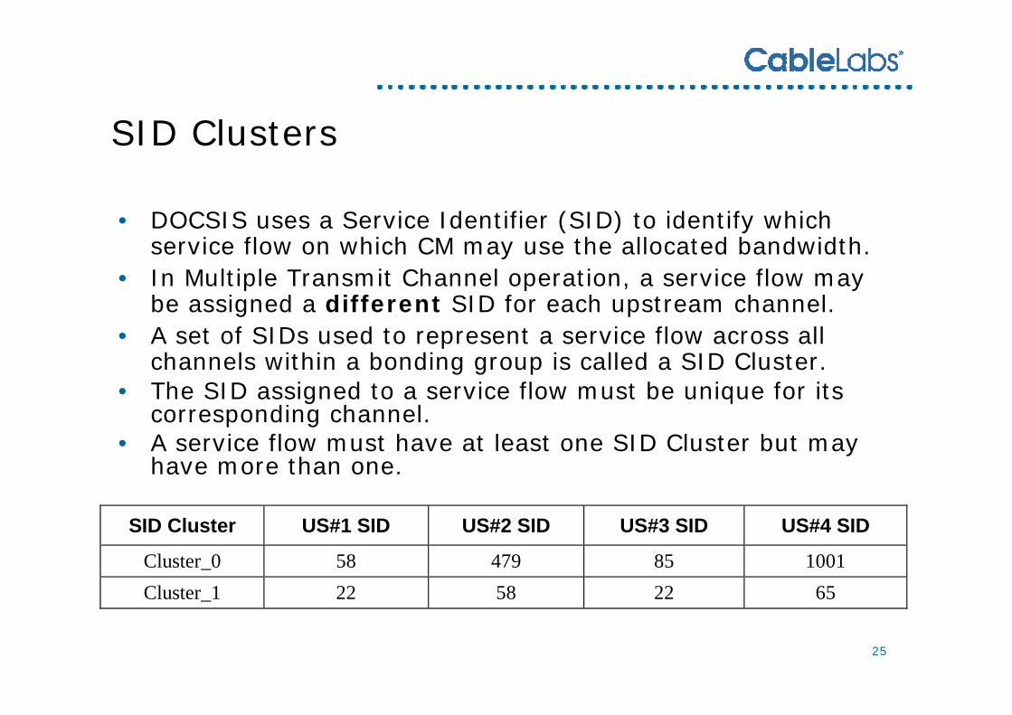
• DOCSIS uses a Service Identifier (SID) to identify which service flow on which CM may use the allocated bandwidth.
• In Multiple Transmit Channel operation, a service flow may be assigned a different SID for each upstream channel.
• A set of SIDs used to represent a service flow across all channels within a bonding group is called a SID Cluster.
• The SID assigned to a service flow must be unique for its corresponding channel.
• A service flow must have at least one SID Cluster but may have more than one.
SID Cluster US#1 SID US#2 SID US#3 SID US#4 SID
Cluster_0 58 479 85 1001 Cluster_1 22 58 22 65
26
Granting BandwidthGranting Bandwidth
• The CMTS uses the legacy MAP structure to send MAPs to cable modems performing upstream channel bonding.
The same MAP is used for legacy and DOCSIS 3.0 CMs.• The CMTS has complete freedom in granting the
bandwidth. It can:Grant any portion or all of the requested bandwidthCombine portions of requests for the same SID Cluster into a single grantGrant on any or all upstream channels associated with the service flow.
• The CMTS grants requests using the requesting SID Cluster’s SID value that is associated with the upstream channel on which the grant is allocated.
• The CMTS sends data grant pendings on at least one channel whenever it has not fulfilled a received request.
• The CMTS adds segmentation overhead and PHY overhead to the grant calculations.
27
AgendaAgenda
• DS Channel Bonding Protocol• Receive Channel Profiles• US Channel Bonding Protocol
HFC Plant Topologies & Resolution
28
Plant Topologies & ResolutionPlant Topologies & Resolution
• DOCSIS 3.0 allows a very flexible deployment path for MSOs
• Supports a wide range of possible plant topologies
• In order to do DS & US channel bonding, CMTS needs to know what channels can physically reach a particular CM
CMTS needs to resolve the CM’s location in the plant topology
29
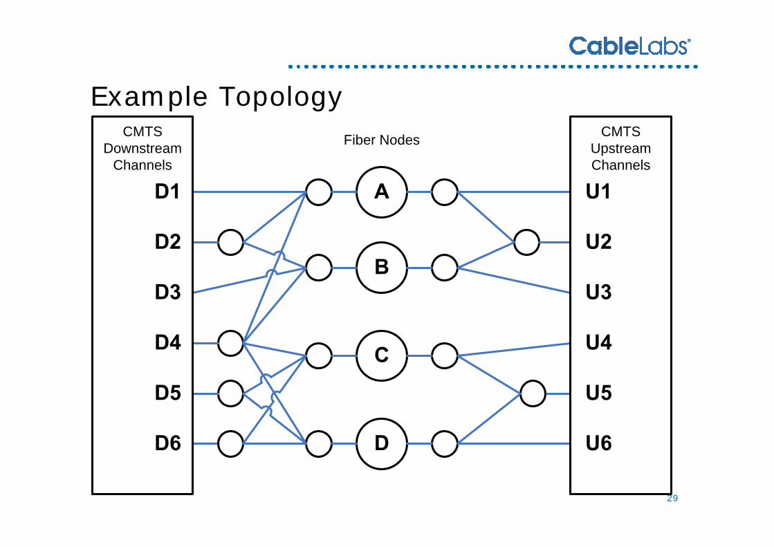
Example TopologyExample TopologyFiber Nodes CMTS
Upstream Channels
CMTSDownstream
Channels
30
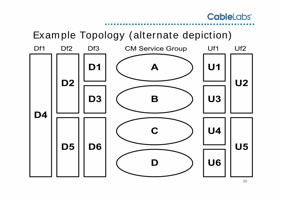
Example Topology (alternate depiction)Example Topology (alternate depiction)
31
Topology Resolution StepsTopology Resolution Steps
• CMTS periodically (every 2 sec) sends a MAC Domain Descriptor (MDD) Message containing:
The Downstream Service Groups in the MAC Domain The Upstream Ambiguity Resolution Channel List
• CM tunes to various channels to determine which Downstream Service Group it is in
• CM selects a channel in the Upstream Ambiguity Resolution Channel List and attempts ranging
• In initial ranging, CM informs CMTS of the resolved DS-SG
• Combination of DS-SG-ID and Upstream Channel are usually enough for CMTS to resolve CM’s location
If not, CMTS can do RNG-RSP channel overrides to further locate the CM
32
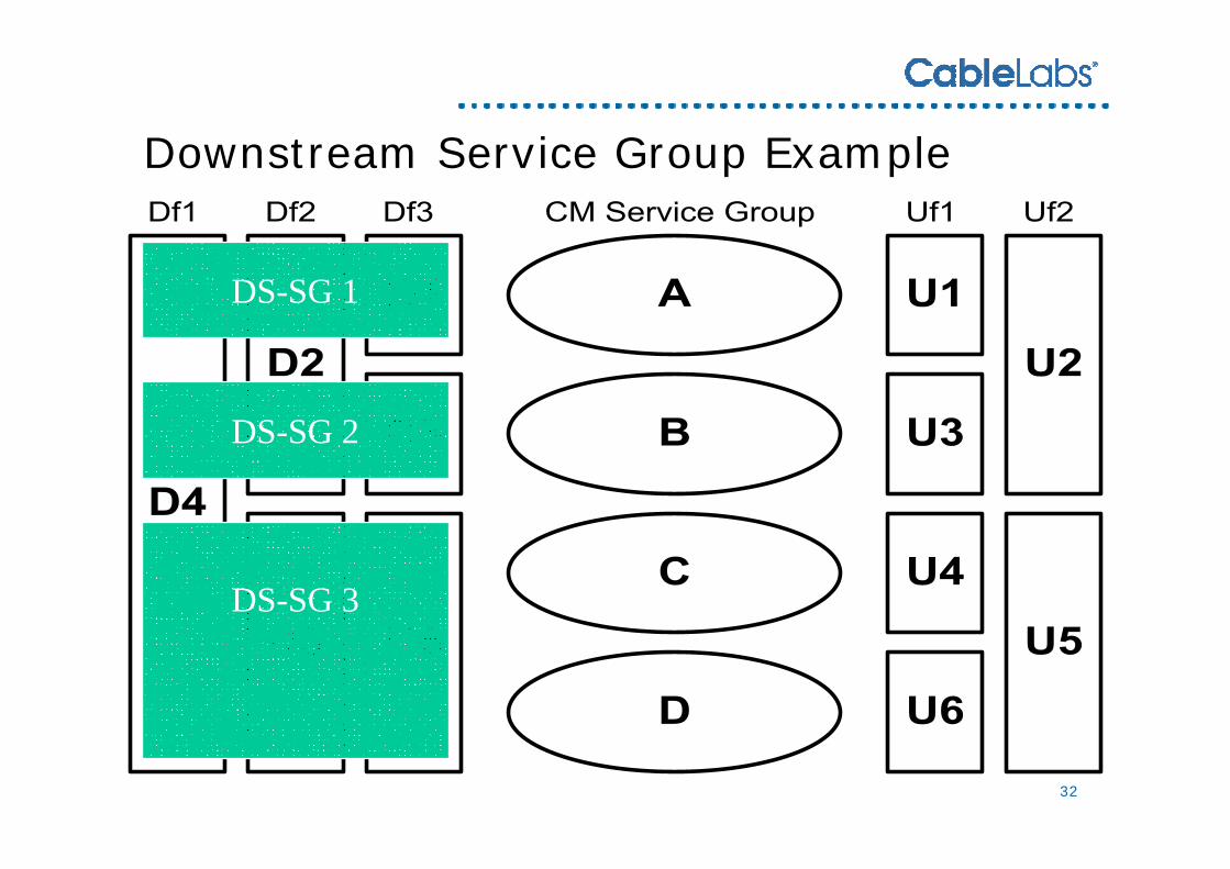
Downstream Service Group ExampleDownstream Service Group Example
DS-SG 1
DS-SG 2
DS-SG 3