Embed Size (px)
DESCRIPTION
The Channel Master CM 3020 is an outdoor TV antenna which will allow you to receive UHF, VHF, FM and HD signals. This antenna has a signal range of 100 miles and will pick up available local channels 2 thru 69. With an HD television you will pick up any crystal clear HD signals being broadcasted in your area.
Citation preview
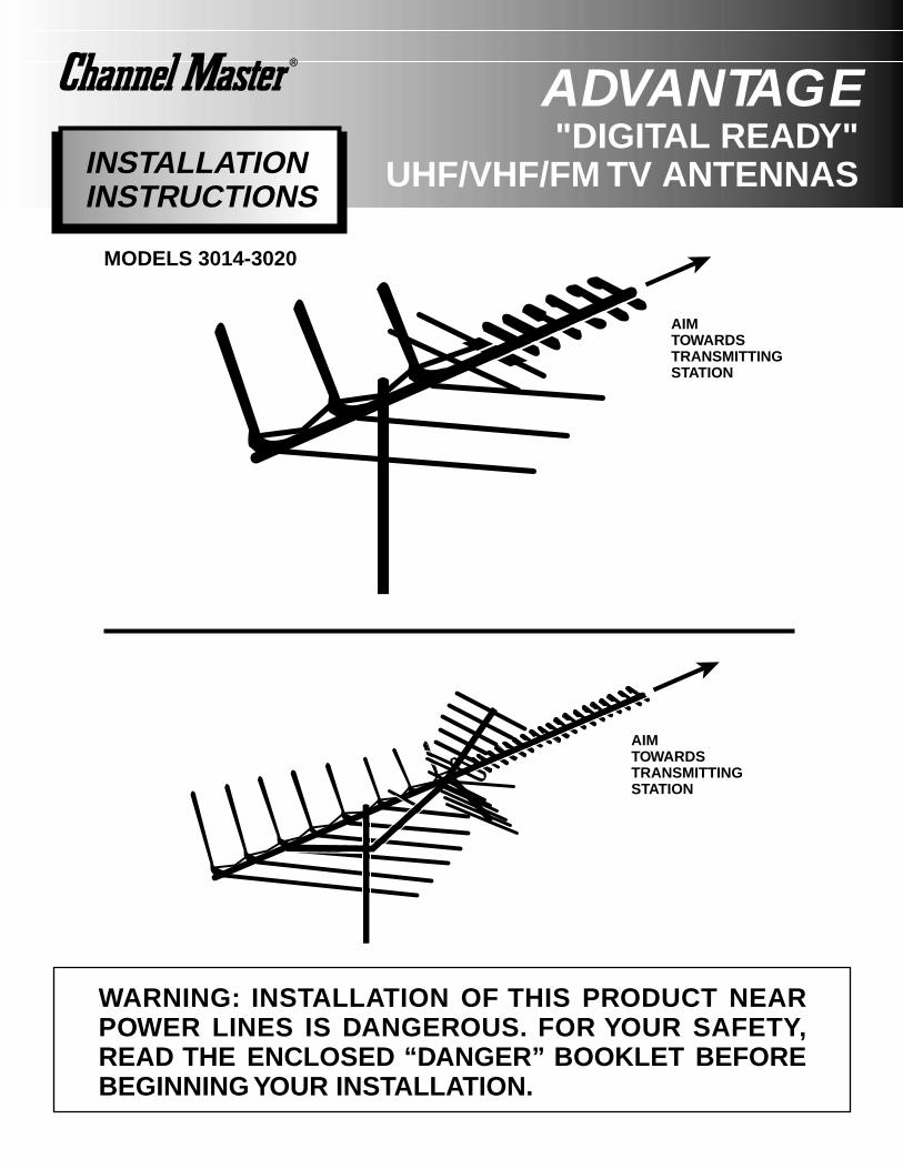
AIMTOWARDSTRANSMITTINGSTATION
AIMTOWARDSTRANSMITTINGSTATION
"DIGITAL READY"UHF/VHF/FM TV ANTENNASINSTALLATION
INSTRUCTIONS
WARNING: INSTALLATION OF THIS PRODUCT NEARPOWER LINES IS DANGEROUS. FOR YOUR SAFETY,READ THE ENCLOSED “DANGER” BOOKLET BEFOREBEGINNING YOUR INSTALLATION.
MODELS 3014-3020
ADVANTAGE
TOOLS YOU WILL FIND HANDY• Large and small blade screwdrivers • Wire Cutters• Adjustable Wrench • Pliers
WHERE TO MOUNT YOUR ANTENNAYour antenna can be mounted on either the chimney, the roof, or on an outside wall or in an attic. Choose themethod that best suits your particular location.
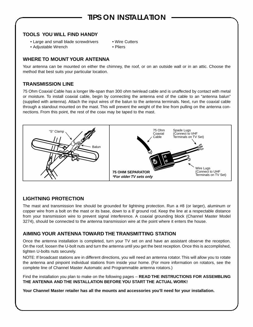
TRANSMISSION LINE75 Ohm Coaxial Cable has a longer life-span than 300 ohm twinlead cable and is unaffected by contact with metalor moisture. To install coaxial cable, begin by connecting the antenna end of the cable to an “antenna balun”(supplied with antenna). Attach the input wires of the balun to the antenna terminals. Next, run the coaxial cablethrough a standout mounted on the mast. This will prevent the weight of the line from pulling on the antenna con-nections. From this point, the rest of the coax may be taped to the mast.
LIGHTNING PROTECTIONThe mast and transmission line should be grounded for lightning protection. Run a #8 (or larger), aluminum orcopper wire from a bolt on the mast or its base, down to a 8’ ground rod. Keep the line at a respectable distancefrom your transmission wire to prevent signal interference. A coaxial grounding block (Channel Master Model3274), should be connected to the antenna transmission wire at the point where it enters the house.
AIMING YOUR ANTENNA TOWARD THE TRANSMITTING STATIONOnce the antenna installation is completed, turn your TV set on and have an assistant observe the reception.On the roof, loosen the U-bolt nuts and turn the antenna until you get the best reception. Once this is accomplished,tighten U-bolts nuts securely.
NOTE: If broadcast stations are in different directions, you will need an antenna rotator. This will allow you to rotatethe antenna and pinpoint individual stations from inside your home. (For more information on rotators, see thecomplete line of Channel Master Automatic and Programmable antenna rotators.)
Find the installation you plan to make on the following pages – READ THE INSTRUCTIONS FOR ASSEMBLINGTHE ANTENNA AND THE INSTALLATION BEFORE YOU START THE ACTUAL WORK!
Your Channel Master retailer has all the mounts and accessories you’ll need for your installation.
TIPS ON INSTALLATION
Spade Lugs(Connect to VHFTerminals on TV Set)
"S" Clamp
Wire Lugs(Connect to UHFTerminals on TV Set)
75 OhmCoaxialCable
75 OHM SEPARATOR*For older TV sets only
Balun

IMPORTANT SAFEGUARDS• Remember, when working on a roof, use two men.• Never walk on a composition roof in cold weather.• Wear sneakers or crepe soles, and use a safety rope.• Always watch for power lines.
ATTIC INSTALLATION:Using a roof mount, attach a short piece of mast to a conven-ient roof rafter. Attach and aim the antenna in the same man-ner as outlined for outdoor installations. NOTE: Antennasshould not be installed in an attic if the roof or walls are metalor are lined with foil backed insulation.
ROOF MOUNT: Used on peaked or flat type roofs.Suggested Height Limit: 10-feet above roof top.Using a roof mount, connect the mast with guy ring and guywires attached, to the mount. Use three or four guy wires,equally spaced around the mast, and anchor the guy wires tothe roof or eaves with eyebolts. The guy ring should beclamped approximately 1-foot below the antenna. Use roofingcompound around the base of the mount, screws and eyeboltsto seal against moisture. After the installation has been com-pleted, mount the extra WARNING LABEL supplied with theantenna hardware to the mast at EYE LEVEL!
CHIMNEY MOUNTING:Suggested Height Limitation: 10 feet above rooftop.First, check your chimney thoroughly for stability to make surethat it is strong enough to support the antenna during severewinds. Do not use a chimney that has loose bricks or mortar.Install the upper bracket just below the top course of bricks andthe lower bracket at least 2¹⁄₂ feet below the top bracket. (Formaximum strength, space the brackets as far apart as possi-ble.) After the installation has been completed, mount the extraWARNING LABEL supplied with the antenna hardware to themast at EYE LEVEL!
WALL MOUNT:Suggested Height Limitation: 10 feet above rooftop.If the roof overhang is not excessive, the side of the house canbe used for mounting. If a wall mounted installation is donefrom the ground up, use a ground mount with a “spike” at theground. Position the wall brackets over a stud if possible; oneabove the other and space a minimum of three feet apart. Formetal siding, mark mounting holes, then drill pilot holesthrough the siding for mounting screws. If you use a 2-piecemast, assemble the pieces as shown, making sure that theya r eproperly locked together. Split between masts should bebetween the two wall brackets. After the installation has beencompleted, mount the extra WARNING LABEL supplied withthe antenna hardware to the mast at EYE LEVEL!
TRIPOD MOUNT: Use on peaked or flat roofs.Suggested Height Limit: 10 feet above roof top.The tripod mount can be mounted to any style roof by adjust-ing the bracket on the center leg. Insert the mast into the tripodmount and place the mount with legs over the roof rafters.Make sure the mast is vertical. Remove the protective coveringfrom one side of the three pitch pads and place under the baseof each tripod leg with the tacky side towards the roof. Securethe tripod mountto the roof using lag screws. After the installation has beencompleted, mount the extra WARNING LABEL supplied withthe antenna hardware to the mast at EYE LEVEL!
ANTENNA REMOVAL:Removal of your antenna should be exactly in reverse of theinstallation instructions. For your own safety, please follow theinstructions for installing the antenna starting with the last stepfirst. This is the only way to safely remove your antenna.
WARNING: INSTALLATION OF THIS PRODUCT NEAR POWER LINES IS DANGEROUS.FOR YOUR SAFETY, READ THE ENCLOSED “DANGER” BOOKLET BEFORE BEGINNING YOUR INSTALLATION.
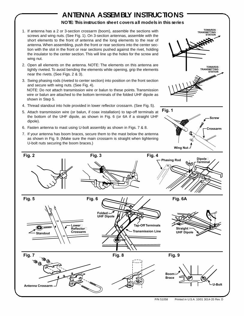
1. If antenna has a 2 or 3-section crossarm (boom), assemble the sections withscrews and wing nuts. (See Fig. 1). On 3-section antennas, assemble with theshort elements to the front of antenna and the long elements to the rear ofantenna. When assembling, push the front or rear sections into the center sec-tion with the slot in the front or rear sections pushed against the rivet, holdingthe insulator to the center section. This will line up the holes for the screw andwing nut.
2. Open all elements on the antenna. NOTE: The elements on this antenna aretightly riveted. To avoid bending the elements while opening, grip the elementsnear the rivets. (See Figs. 2 & 3).
3. Swing phasing rods (riveted to center section) into position on the front sectionand secure with wing nuts. (See Fig. 4).NOTE: Do not attach transmission wire or balun to these points. Transmissionwire or balun are attached to the bottom terminals of the folded UHF dipole asshown in Step 5.
4. Thread standout into hole provided in lower reflector crossarm. (See Fig. 5).
5. Attach transmission wire (or balun, if coax installation) to tap-off terminals atthe bottom of the UHF dipole, as shown in Fig. 6 (or 6A if a straight UHFdipole).
6. Fasten antenna to mast using U-bolt assembly as shown in Figs. 7 & 8.
7. If your antenna has boom braces, secure them to the mast below the antennaas shown in Fig. 9. (Make sure the main crossarm is straight when tighteningU-bolt nuts securing the boom braces.)
ANTENNA ASSEMBLY INSTRUCTIONSNOTE: This instruction sheet covers all models in this series
Crossarm
Screw
Wing Nut
Phasing Rod Dipole�Terminal
Standout
Lower�Reflector�Crossarm
Antenna Crossarm
Boom�Brace
U-Bolt
Straight�UHF Dipole
Folded�UHF Dipole
Tap-Off Terminals
Transmission Line
Fig. 1
Fig. 2 Fig. 3 Fig. 4
Fig. 5 Fig. 6 Fig. 6A
Fig. 7 Fig. 8 Fig. 9
TOWARDS�TRANSMITTING�
STATION
TOWARDS�TRANSMITTING�
STATION
P/N 51058 Printed in U.S.A. 10/01 3014-20 Rev. D