Embed Size (px)
Citation preview

IEEE802.3 4P Task Force
Channel Pair To Pair Resistance Imbalance(End to End System Imbalance)
Ad HocMeeting #1: Rev_001 Monday February 17, 2014Meeting #2: Rev_002 Monday February 24, 2014
March 2014Beijing China
Yair Darshan Microsemi

Channel Pair To Pair Resistance Imbalance (End to End System Imbalance) Ad Hoc rev 001b , March 2014
Yan Zhuang / Huawei
Abramson David / TI
Kousalya Balasubramanian/ Cisco
Leonard Stencel / Bourns
Larsen Wayne / Commscope
Woudenberg Rob / Philips
Picard Jean / TI
Steinke Stephan / Molex
George Zimmerman / CME Consulting / Commscope
Sesha Panguluri/Broadcom
Ken Bennett/ Sifos
Meeting # 1 Attendees (Monday Feb 17,2014)
2
Gaoling Zou / Maxim
Dave Dwelley / LT
Lennart Yseboodt / Philips
Wendt, Matthias / Philips
Christian Beia / ST
David Law / Hp

Channel Pair To Pair Resistance Imbalance (End to End System Imbalance) Ad Hoc rev 001b , March 2014
• Introduction
• Summary of previous work and conclusions
• Cable pair to pair resistance unbalance (P2PRU)
• Channel pair to pair resistance unbalance (C_P2PRU)
• General Channel Model and its components
• Simulation Results
• Sensitivity Analysis
• Conclusions
• What are the parameters that must be define?
• Cable Pair to Pair Resistance Unbalance (P2PRU)
• Channel Pair to Pair Resistance Unbalance (C_P2PRU)
• Analysis Methods and Data-Base
• Analysis Method
• Data Base
• Do we need to specify the following additional parameters or leave it to be
implementation specific as long as C_P2PRU is met?
• PSE PI Pair to Pair Resistance Unbalance (PSE_P2PRU)
• PD PI Pair to Pair Resistance Unbalance (PD_P2PRU)
Proposed Agenda
3

Channel Pair To Pair Resistance Imbalance (End to End System Imbalance) Ad Hoc rev 001b , March 2014
• The purpose of this ad-hoc is to recommend the Task-Force for what is needed to specify the channel pair to pair resistance unbalance while considering not only the formal channel components (Cable and Connector) but also the Power Interface (PI) components at both ends of the 4P PoE system.
• Patent Policy
• All attendees to send mail approving their attendance at the add-hoc today
Introduction
4
Channel Pair To Pair Resistance Imbalance (End to End System Imbalance) Ad Hoc rev 001b , March 2014
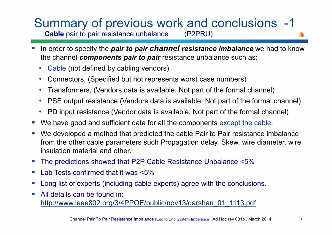
In order to specify the pair to pair channel resistance imbalance we had to know
the channel components pair to pair resistance unbalance such as:
• Cable (not defined by cabling vendors),
• Connectors, (Specified but not represents worst case numbers)
• Transformers, (Vendors data is available. Not part of the formal channel)
• PSE output resistance (Vendors data is available. Not part of the formal channel)
• PD input resistance (Vendor data is available, Not part of the formal channel)
We have good and sufficient data for all the components except the cable.
We developed a method that predicted the cable Pair to Pair resistance imbalance
from the other cable parameters such Propagation delay, Skew, wire diameter, wire
insulation material and other.
The predictions showed that P2P Cable Resistance Unbalance <5%
Lab Tests confirmed that it was <5%
Long list of experts (including cable experts) agree with the conclusions.
All details can be found in:
http://www.ieee802.org/3/4PPOE/public/nov13/darshan_01_1113.pdf
5
Summary of previous work and conclusions -1Cable pair to pair resistance unbalance (P2PRU)

Channel Pair To Pair Resistance Imbalance (End to End System Imbalance) Ad Hoc rev 001b , March 2014
Initial Work to determine channel pair to pair resistance unbalance:
• http://grouper.ieee.org/groups/802/3/4PPOE/public/jul13/beia_1_0713.pdf
• http://grouper.ieee.org/groups/802/3/4PPOE/public/jul13/darshan_2_0713.pdf
• After getting comments from the group and using same worst-case data
base and model:
• http://www.ieee802.org/3/4PPOE/public/nov13/darshan_03_1113.pdf
• http://www.ieee802.org/3/4PPOE/public/nov13/beia_01_1113.pdf
• General Channel Model and its components that we have used: See next
slide.
Summary of previous work and conclusions -2Channel pair to pair resistance unbalance (C_P2PRU)
6

Channel Pair To Pair Resistance Imbalance (End to End System Imbalance) Ad Hoc rev 001b , March 2014
Summary of previous work and conclusions -3General Channel Model and its components that we have used.Updated Model to include equipment connector for accurate end to end worst case analysis.
7
Notes for the general Model:
1. Adding resistors on
positive path for general
model per previous
discussion (Rsp_a and
Rsp_b). It can be set to
zero or >zero pending
the case being
investigated.
2. Adding equipment
connectors per Wayne’s
comment. So total end
to end channel
connectors is 6.
3. The formal channel
definition is marked in
red arrow.
4. Our work addresses
also the internal
application resistance of
known components that
are used
I didn’t include the "equipment connectors"
which is the point of PI=Power Interface
per the specifications language which is
the equipment connectors.
The equipment connectors are not part of
the formal channel HOWEVER you are
correct that I need to include it in worst
case analysis since I include all real
channel affecting factors such
transformers, sense resistors, diodes etc.
As a result, I will include it and recalculate
the worst case pair to pair channel
resistance imbalance.
Actually I have these extra connectors in
the drawings (marked PI ) but I didn’t
include their effect at the simulations.
Drawing 1

Channel Pair To Pair Resistance Imbalance (End to End System Imbalance) Ad Hoc rev 001b , March 2014
Two scenarios have been identified: max wire resistivity Data set 1 (CAT5E cables) and min wire resistivity Data set 2 (CAT6/A cables)
• *Cable pair to pair resistance max unbalance is set to 5%. See darshan_1_1113.pdf. Cable resistance within pair unbalance is max 2%.
• **Connector contact aging will be addressed in other work.
• All parameters are at room temperature and further study is required to address temperature variations
Summary of previous work and conclusions -4Data set that we use as worst case numbers
8
Table 1 Data set 1 (Max Cable resistivity) Data set 2 (Min Cable resistivity)
Cable resistivity 117mOhm/m* (maximum value) (CAT5e)
Pair resistance unbalance: 2%
Minimum wire resistance=0.98*117mΩ/m
Pair to pair resistance unbalance: 5%
Pair resistance max=~(117mΩ/m)/2
Pair resistance min=~(0.95*117mΩ/m)2
66mOhm/m* (CAT6A)
Pair resistance unbalance: 2%
Minimum wire resistance=0.98*66mΩ/m
Pair to pair resistance unbalance: 5%
Pair resistance max=~(66mΩ/m)/2
Pair resistance min=~(0.95*66mΩ/m)2
Transformer winding
resistance
120mOhm min, 130mOhm max 120mOhm min, 130mOhm max
Contact resistance 30mOhm min, **
60mOhm max
30mOhm min, **
60mOhm max
Diode bridge 0.3V+0.4Ohm*Id min;
0.4V+0.5Ohm*id max
0.3V+0.4Ohm*Id min;
0.4V+0.5Ohm*id max
PSE output resistance
(e.g. Rs_a/b=
Rsense+Rdson)
0.25+0.1 Ohm min
0.25+0.2 Ohm max
0.1+0.05 Ohm min
0.1+0.1 Ohm max
From: http://www.ieee802.org/3/4PPOE/public/nov13/beia_01_1113.pdf

Channel Pair To Pair Resistance Imbalance (End to End System Imbalance) Ad Hoc rev 001b , March 2014
Results for Table 1 right column data number set (minimum resistivity cable Type).
Pairs were not limited to 0.6A
Numbers were taken from the pairs with highest and lowest values.
The model that was simulated is with 4 connectors only as in the link below.
http://www.ieee802.org/3/4PPOE/public/nov13/darshan_03_1113.pdf
Summary of previous work and conclusions -5Simulation Results (updates from last meeting)
9
Simulation Results of worst-case analysis
Length[m]
Pair with
minimum
current[mA]
Pair with
maximum
current[mA]
Idiff=Max-Min[mA]
P2PCRunb[%]
1 385 659 275 26.30
10 415 636 221 21.04
100 500 626 126 11.19
inax
inaxPCRUNBP
ImIm
ImIm2
+
−=

Channel Pair To Pair Resistance Imbalance (End to End System Imbalance) Ad Hoc rev 001b , March 2014
Results with 6 connectors Model. -6Simulation Results
10
Results for Table 1 right column data number set (minimum resistivity cable Type).
Pairs were not limited to 0.6A
Numbers were taken from the pairs with highest and lowest values.
The model used is per
Simulation Results of worst-case analysis with 4 connectors
Length[m]
Pair with
minimum
current[mA]
Pair with
maximum
current[mA]
Idiff=Max-Min[mA]
P2PCRunb[%]
1 385 659 275 26.30
10 415 636 221 21.04
100 500 626 126 11.19
Simulation Results of worst-case analysis with 6 connectors TBD
Length[m]
Pair with
minimum
current[mA]
Pair with
maximum
current[mA]
Idiff=Max-Min[mA]
P2PCRunb[%]
1
10
100

Channel Pair To Pair Resistance Imbalance (End to End System Imbalance) Ad Hoc rev 001b , March 2014
See details: http://www.ieee802.org/3/4PPOE/public/nov13/beia_01_1113.pdf
What we did was a sensitivity Analysis to identify the main contributors of lesser power delivery.
We need to do the work for sensitivity analysis for channel pair to pair resistance unbalance regardless of power delivery constrains.
Summary of previous work and conclusions -7
11
Max res scenario
Component
UNB[±]
Effect on power delivery
[-]
Cable
lenght 1m 10m 100m
Rt 4% 0.17% 0.10% 0.01%
Rconn 33.30% 1.02% 0.58% 0.08%
r_cable 5% 0.20% 1.13% 1.68%
Rdiode 11.10% 3.43% 1.96% 0.32%
Vdiode 14.30% 5.72% 3.27% 0.53%
Min res scenario
Component
UNB[±]Effect on power delivery
[-]
Cable
lenght 1m 10m 100m
Rt 4% 0.18% 0.12% 0.03%
Rconn 33.30% 1.06% 0.73% 0.16%
r_cable 5% 0.12% 0.81% 1.79%
Rdiode 11.10% 3.56% 2.48% 0.57%
Vdiode 14.30% 5.94% 4.14% 0.96%
Channel Pair To Pair Resistance Imbalance (End to End System Imbalance) Ad Hoc rev 001b , March 2014
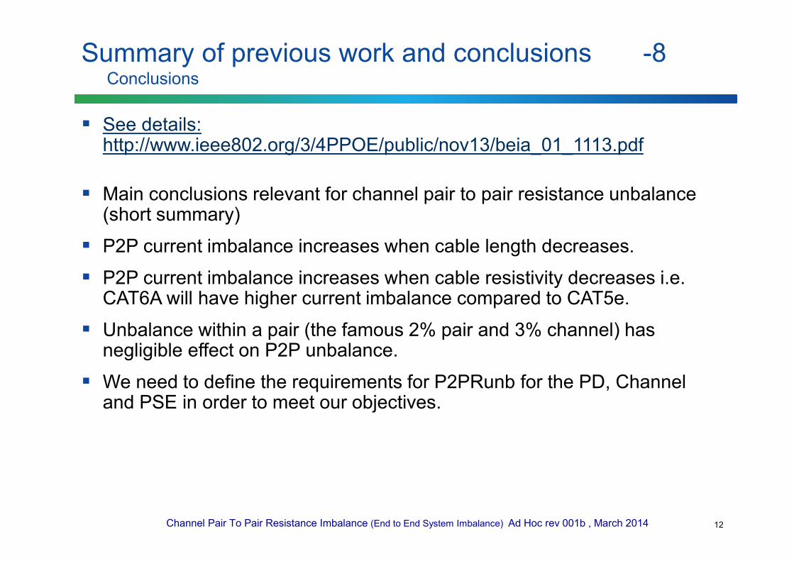
See details: http://www.ieee802.org/3/4PPOE/public/nov13/beia_01_1113.pdf
Main conclusions relevant for channel pair to pair resistance unbalance (short summary)
P2P current imbalance increases when cable length decreases.
P2P current imbalance increases when cable resistivity decreases i.e. CAT6A will have higher current imbalance compared to CAT5e.
Unbalance within a pair (the famous 2% pair and 3% channel) has negligible effect on P2P unbalance.
We need to define the requirements for P2PRunb for the PD, Channel and PSE in order to meet our objectives.
Summary of previous work and conclusions -8Conclusions
12

Channel Pair To Pair Resistance Imbalance (End to End System Imbalance) Ad Hoc rev 001b , March 2014
To analyzed the following scenarios:
• How connector contact aging will affect the results i.e. if min/max contact resistance difference will be increased.
• The current unbalance results as function of operating temperature range
• To analyze the results when there is no hard limit of 600mA on the negative pair.
(Done: See slide “results” and see: http://www.ieee802.org/3/4PPOE/public/nov13/darshan_03_1113.pdf
• To set a worst case conditions for evaluating maximum current imbalance through transformers.
Actually done: Ibias=Iunbalance/2=CP2PRU*Icable_max.
• Consider analyzing P2P current imbalance higher category cables than CAT6A
• To perform sensitivity analysis for P2P current and resistance imbalance.
Summary of previous work and conclusions -9Conclusions
13

Channel Pair To Pair Resistance Imbalance (End to End System Imbalance) Ad Hoc rev 001b , March 2014
• As done in IEEE802.3-2012 (See Annex A) when we define the pair
(wire to wire in the same pair) in the cable pair(s) and in the channel,
we need to do it for the Pair to Pair Resistance Unbalance in the cable
and in the channel.
• Cable Pair to Pair Resistance Unbalance (P2PRU)
• Based on the work done at
http://www.ieee802.org/3/4PPOE/public/nov13/darshan_01_1113.pdf , it is
proposed to specify it to 5% until formal number will be received from
TIA/EIA.
• Channel Pair to Pair Resistance Unbalance (C_P2PRU)
• We need to decide if we can work with the worst case numbers?
• Or we need to add the probability factors to lower them.
What are the parameters that must be define?
14

Channel Pair To Pair Resistance Imbalance (End to End System Imbalance) Ad Hoc rev 001b , March 2014
• Analysis Method
• Worst-Case Analysis
• We did a worst-case analysis for the channel pair to pair resistance unbalance on a proposed worst-case data
• Any comments on the worst-case data base?
– To considering 100BaseT Ethernet devices or switches that do not implement transformers on the spare pairs so the range should be 0 Ohm to 130mOhm.
• In the switch and PD vendor will have to add equivalent resistor to compensate the PSE PI unbalance. To discuss this approach.
• Any comments on the model used
• Next Steps
• Are we Ok with the results obtain and can live with it or we need to do a statistical analysis to lowering the numbers of worst-case analysis?
Analysis Methods and Data-Base
15

Channel Pair To Pair Resistance Imbalance (End to End System Imbalance) Ad Hoc rev 001b , March 2014
• Do we need to specify the following additional parameters or leave it to be implementation specific as long as C_P2PRU is met?
• PSE PI Pair to Pair Resistance Unbalance (PSE_P2PRU)
• PD PI Pair to Pair Resistance Unbalance (PSE_P2PRU)
• In the current standard the pair resistance unbalance was defined to 2% and the channel
(cable and connector only) to 3% (See Annex A).
• It was the responsibility of the equipment vendor to make sure that his design will meet
all system requirement based on the above specification.
• In 802.3at extensive work was done and shows that the actual pair channel resistance
unbalance is higher than 3% (due to other components in the system) and yet system
vendors and components ensure operation under this conditions.
• Now we are addressing the P2P channel Resistance Unbalance and we have the same
question: Do we need to specify the following additional parameters or leave it to be
implementation specific as long as C_P2PRU is met?
• If we do want to define PSE_P2PRU and PD_P2PRU.
• Should we define only PD_P2PRU since it is not always required for the PD (it is PD
power dependent and if defined at PSE it will be required for every port
Do we need to specify PSE and PD PI P2P Resistance Unbalance or leave it to be implementation specific as long as C_P2PRU is met?
16

Channel Pair To Pair Resistance Imbalance (End to End System Imbalance) Ad Hoc rev 001b , March 2014
To ask magnetic component vendors if they can handle the worst-case analysis numbers or we should
do statistical analysis as well.
• If they can, we use the results to define the end to end channel P2P resistance unbalance.
To define 3 new parameters
(1) To define the channel (PI to PI) Resistance unbalance (cables and connectors) with the
contributions of PSE and PD PI P2P Resistance Unbalance.
From (1) to separately define
• PSE PI P2PRUNB and PD P2PRUNB
• To define the channel (PI to PI) Resistance unbalance (cables and connectors).
• As a result component and system vendors could use it for designing their components.
We accept that P2P Cable Resistance Unbalance is 5% until formal number will be received by TIA/EIA
etc.
Yair to work with transformer vendors to get the data we need.
To look for the best cable (lower resistance per meter) expected in the next 10+years and use it in our
worst case data base numbers.
To verify that LDO is covered by PD constant power sink.
To considering 100BaseT Ethernet devices or switches that do not implement transformers on the spare
pairs so the range should be 0 Ohm to 130mOhm.
• In the switch and PD vendor will have to add equivalent resistor to compensate the PSE PI
unbalance. To discuss this approach.
No other comments on previous work done nor on model or database used.
Group to send comments on model and data base and we will update it if found.
Discussions and conclusions
17

Channel Pair To Pair Resistance Imbalance (End to End System Imbalance) Ad Hoc rev 001b , March 2014
To discuss the advantages that PD constant Power Sink allows us.
Background material for considering:
• Worst case Channel Pair to Pair Channel Resistance Unbalance is at short cable (<100m).
• At short cables PD voltage is higher that at 100m channel length and pair/port current is lower
• Not only that the port current is lower, it is <600mA for Type 3 systems below TBD channel length.
• As a result, P2PCRUNB is not an issue.
• At 100m the P2PCRUNB is much smaller than at short channel
• Resulting with less significant contribution to Ibias due to P2PCRUNB and as a result to OCL. This approach was validated in: http://grouper.ieee.org/groups/802/3/4PPOE/public/jul13/darshan_2_0713.pdf and requires further investigation for completing this work.
For next meeting -1
18
Illustration of the behavior.(The curve is not linear. It is just describing the trend.)
Channel Pair To Pair Resistance Imbalance (End to End System Imbalance) Ad Hoc rev 001b , March 2014
We need to define the PD load current on Mode A and Mode B in which below that current, P2P requirements can be ignored.
• Example: if Mode A requires 350mA and Mode B require 113mA than P2P discussion is not relevant to this case.
For next meeting -2
19

Channel Pair To Pair Resistance Imbalance (End to End System Imbalance) Ad Hoc rev 001b , March 2014
To specify test setup as well
PSE_PI Pair to Pair Resistance Unbalance
20
Channel Pair To Pair Resistance Imbalance (End to End System Imbalance) Ad Hoc rev 001b , March 2014
Same concept for PD PI P2P_R_UNB definitions
To specify test setup
PD_PI Pair to Pair Resistance Unbalance
21

Channel Pair To Pair Resistance Imbalance (End to End System Imbalance) Ad Hoc rev 001b , March 2014
The way channel pair (the differences between two wires in a pair) resistance unbalance was defined.
Annex A
22