Embed Size (px)
DESCRIPTION
notes
Citation preview

1
CC603CC603PROJECT MANAGEMENTPROJECT MANAGEMENT
Department of Civil EngineeringDepartment of Civil EngineeringPolytechnic Port DicksonPolytechnic Port Dickson
TOPIC : 3 SITE SUPERVISION AND ORGANISATION
Nawawi Jalil, Azizah Tukiman, Marlya Dahuri, Ahmad Zaidi Mispan

SYLLABUS:SYLLABUS:3.1 UNDERSTAND THE SITE PLANNING & PROGRESS CHART3.1.1Demonstrate the usage of the bar chart & gantt chart.3.1.2 Indicate the arrow method in site planning.3.1.3 Demonstrate the critical path method.3.2 KNOW THE DUTIES OF TECHNICIAN & ASSISTANT ENGINEER3.2.1 Show the duty of a technician or a site supervisor3.2.2 Relate the duty of a technician with an assistant engineer.3.2.3 Prepare a site diary.3.3 KNOW THE PLANKING & STRUTTING FOR SHALLOW
EXCAVATION3.3.1 Define, describe techniques and state the safety precaution for;a. Good slopeb. Moderately firm groundc. Loose soil
2
SYLLABUS:SYLLABUS:3.4 KNOW THE TYPES OF SCAFFOLDING IN CONSTRUCTION3.4.1 Compare, describe the techniques and state the safety precaution for;a. Steps scaffoldingb. Bracket/birdcage scaffoldingc. Single scaffoldingd. Couple scaffoldinge. Cantilever scaffoldingf. Hanging/ suspended scaffolding3.5 KNOW THE TYPES OF STRUT IN CONSTRUCTION3.5.1 Apply, describe the techniques and state the safety precautions for:a. Raking strutb. Horizontal strutc. Vertical/ dead strut.3.6 UNDERSTAND THE CONSTRUCTION OF FORMWORK3.6.1 Illustrate the technique to shoring the formwork.
3
3.1.1Demonstrate the usage of the bar chart & gantt chart.3.1.1Demonstrate the usage of the bar chart & gantt chart.
Develop by Henry Gantt. Definitions
A graphical description of the project consisting of well-defined collection of tasks.
Activity
An activity is a task or closely related group of tasks whose performance contributes to the completion of the overall project. “Excavate Foundation”.
4

Bar Charts are the easiest and most widely used form of scheduling in construction management
Even with other scheduling techniques the eventual schedule is presented the form of a bar chart
A typical Bar chart is a list of activities with the start, duration and finish of each activity shown as a bar plotted to a time scale
The level of detail of the activities depends on the intended use of the schedule.
5

Bar Charts are the easiest and most widely used form of scheduling in construction management
Even with other scheduling techniques the eventual schedule is presented the form of a bar chart
A typical Bar chart is a list of activities with the start, duration and finish of each activity shown as a bar plotted to a time scale
The level of detail of the activities depends on the intended use of the schedule.
6

When scheduling and monitoring tasks within a project.
When communicating plans or status of a project.
When the steps of the project or process, their sequence and their duration are known.
When it’s not necessary to show which tasks depend on completion of previous tasks.
7
When to Use Bar Charts/Gantt Charts??

Advantages
Easy to prepare
Easily understood by all parties
It shows the total plan in impact form.
Good communication tool
Disadvantages
Do not show interrelationships between activities
Managing projects becomes difficult without those relationships between activities
It is difficult to judge the impact of an unexpected event on the rest of the construction process
8
Advantages& Disadvantages Bar Charts/Gantt Charts??

3.1.2 Indicate the arrow method in site 3.1.2 Indicate the arrow method in site planning.planning.
An arrow diagramming method (ADM) is a network diagramming technique in which activities are represented by arrows.
It is used for scheduling activities in a project plan.
The precedence relation between activities is represented by circles connecting to one or more arrows. The length of the arrow represents the duration of the relevant activity.
9

3.1.3 Demonstrate the Critical path 3.1.3 Demonstrate the Critical path method (CPM)method (CPM) Critical Path Method is a network method. In CPM
the project is analysed into different activities whose relationships are shown on the network diagram.
The limitations of the bar charts can be over come with the Critical Path Method. CPM is widely used in construction industry by a number of private and public organisations.
Indicated as Network Diagrams: Any schematic display of the logical relationship
of project activities. Always drawn from left to right to reflect project
chronology. Usually a combination of arrows and nodes.
10

Two types of Critical Path Method : Arrow Diagram (Activity-on-arrow diagram) – AOA
Node Diagram / Precedence Diagram (Activity-on-node diagram)- AON
11
A(3)
B(3)
C(4)
D(6)
E(5)

Arrow Diagrams Activities shown by Arrows. Relationship between activities
shown by nodes / events. Length of arrows does not obey any scale. Start-to-finish relationships. Dummies. Numbering of nodes / events. Milestones
12

Node Diagrams Activities shown by Nodes, relationship between
activities shown by arrows or links. Easier to construct. Generally no need of dummies. Instead dummies
used only to give single start or finish. CPM Calculations similar to Arrow diagrams.
13
A(3)
B(3)
C(4)
D(6)
E(5)

3.20: Know the duties of a technician and 3.20: Know the duties of a technician and assistant engineerassistant engineer
The duty of a technician or a site supervisor : > Supervising construction sites
> Look after the welfare of employees
> Ensure that the materials in good condition
(cement, bricks and others)
14
The duties of an assistant engineer:
> Translate drawings and ensure that work on construction sites in accordance with the drawings
> Solve the problems / confusion about the drawing by the main contractor and sub contractors
> Doing as directed by the construction manager

3.2.3 PREPARE A SITE DIARY3.2.3 PREPARE A SITE DIARY
A Site Diary is a document of "first record“ A formal record of the progress of the works
including any events which may have affected the progress and quality of the finished worked.
This document usually includes: > The date and weather conditions > The numbers of workers in various trade > Materials delivered to the site, the quality
used an retained > Items of plant on site, working or idling,
including reasons for being idle
15

This document usually includes (cont’d):> Any correcting activities, the location and quantity of
the mixes poured. > A brief description of the completed work with the approximate amount done
> Any work carried out in connection with the utility service
> Instruction issued to the contractor Having checked and agreed on all informations which is
entered by the site foremen or the inspector, the site agent who is the contractor’s representative, will sign the site diary.
16
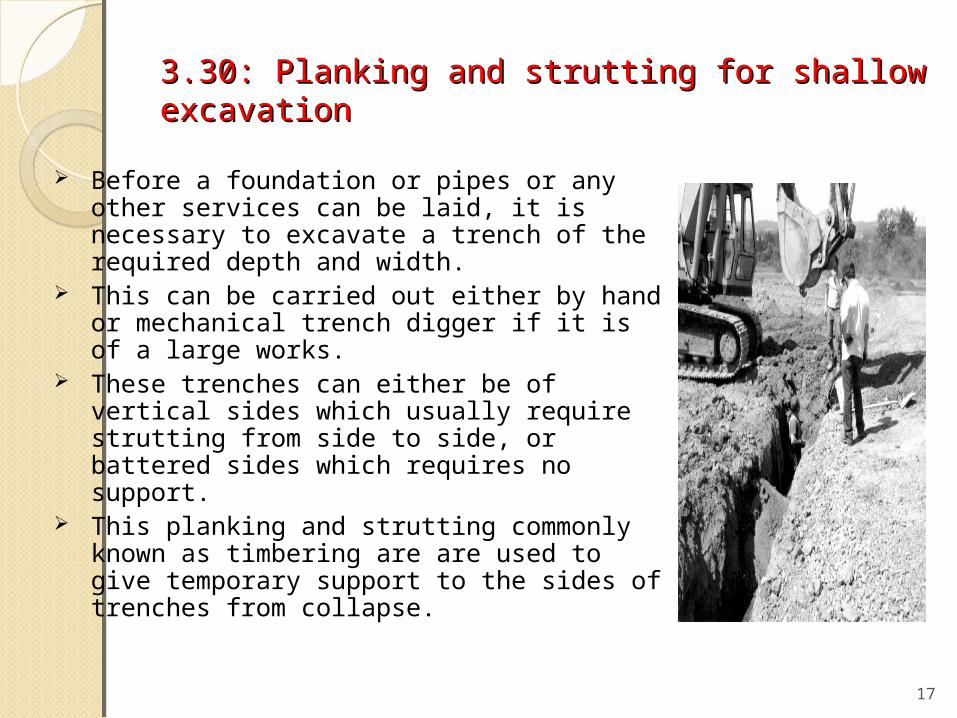
3.30: Planking and strutting for shallow 3.30: Planking and strutting for shallow excavationexcavation
Before a foundation or pipes or any other services can be laid, it is necessary to excavate a trench of the required depth and width.
This can be carried out either by hand or mechanical trench digger if it is of a large works.
These trenches can either be of vertical sides which usually require strutting from side to side, or battered sides which requires no support.
This planking and strutting commonly known as timbering are are used to give temporary support to the sides of trenches from collapse.
17

3.30: Planking and strutting for shallow 3.30: Planking and strutting for shallow excavationexcavation
This sides of some excavations will be need support to:-
- Protect the operative while working in the
excavation
- Keep the excavation open by acting as a
retaining wall to the sides of the trench
Excavations may be classified as shallow, medium or deep in the following manner:-
18
Depth
Shallow Up to 1.5 m
Medium 1.5 to 3.0 m
Deep Over 3.0 m

3.30: Planking and strutting for shallow 3.30: Planking and strutting for shallow excavationexcavation
Planning before digging :
Planning reduces the chance that something
will go wrong when you start a job. Consider
the following before you start excavating:
• Debris near the excavation site that could create a hazard
• How employees will get in and out of the excavation
• How to protect people from falling into the excavation
• How to respond to emergencies
19

3.30 : Planking and strutting for shallow 3.30 : Planking and strutting for shallow excavation excavation
• Location of overhead power lines and underground utility lines
• Possibility of atmospheric hazards in the excavation
• Possibility of water in the excavation
• Stability of soil at the excavation site
• Stability of structures adjacent to the excavation site
• Vehicles and other mobile equipment that will operate near the excavation
• Weather conditions
20

SOIL CATEGORIES - THREE MAIN TYPES
Stiff and Firm Soils – solid soils with substantial cohesion and no water table present (good clay, stiff clay till, medium till). Soils likely to crack or crumble – soils that can be excavated by hand tools, show signs of cracking
after excavating, and possess a low medium moisture content (heavily seamed silty clays, compacted clayey fill, and mixtures of clays and silts).
Soft and loose soils – soils easily excavated by hand with little or no cohesion (i.e. sand,
gravel, silt, organic soil, soft and wet clay and loose fill).
21

Excavation in Excavation in FirmFirm Ground Ground
, called Politics or Poling Boards, are placed in pairs opposite one another against either side of the trench, and are held in position by means of struts.
These struts, which are usually short lengths of 4 inches diameter scaffold poles, or 4 by 4-inch squared timbers, and cut about £ inch longer than the clear distance between a pair of poling boards, are fixed in position in the following manner:
22
The method of timbering a trench in firm ground, in which case short deal and batten "ends," varying from 1 by 4 1/2 inches to 1 1/2 by 9 inches, and about 3 feet long,

These struts, which are usually short lengths of 4 inches diameter scaffold poles, or 4 by 4-inch squared timbers, and cut about £ inch longer than the clear distance between a pair of poling boards, are fixed in position in the following manner:
23
One end of the strut is placed against the middle of one poling board, and the other end is swung vertically downwards against the opposite poling board, and forced tightly against it by means of a few downward taps with a mallet. The struts should not be closer together than 6 feet, otherwise they will prove a considerable inconvenience to the workmen in the trenches

Excavations InExcavations In Loose Loose SoilSoil
Should the looseness of the soil necessitate supports being fixed at closer intervals than 6 feet the system of timbering
In this case it will be noted that the poling boards are supported by long horizontal members about 6 by 4 inches, called Walings or Waling Pieces, which in turn are supported by struts at intervals of 6 feet.
24

3.4 Know the types of scaffolding in 3.4 Know the types of scaffolding in constructionconstruction
Scaffolding is a temporary platform constructed for reaching heights above arms' reach for the purpose of building construction, maintenance, or repair
Scaffolding is generally made of lumber and steel and can range from simple to complex in design, depending on its use and purpose. 25

Millions of construction workers, painters, and building maintenance crews work on scaffolding every day, and due to the nature of its use, scaffolding must be properly constructed and used to ensure the safety of those who use it.
26

FUNCTION As a working platform:
- so that the worker can stand on the platform
do the work easily & safely As a platform for placing material & logistic
needed by the workers to carry out their job As a platform and walking passage:
- scaffolding support the platform that been
used by the worker as their walking path to
transport the material & logistic
27

Factor considered during design stageFactor considered during design stage
Among the factors need to be considered during the design process of scaffold are as
follows:a) Easier to be erectedb) Strongc) Light / Not heavyd) Safee) Suitablef) Passage Link / Passage
connecting to other places28

i. Steps Scaffoldingi. Steps Scaffolding
This scaffold is the most useful ascending aid for activities involving frequent ascent/descent and transport of loads.
Slanting steps reaching from platform to platform with 100 mm deep steps can safely and comfortably be traversed forwards and backwards.
Stairway rails add to the all round safety. No tools required, spacing of platforms by every two meters
ease assembling or dismantling of the tower. 200 mm dia swivel castors with locking device and height
adjusters to cope with uneven surfaces for ease of mobility and handling.
All individual parts are separately available as apares or extension parts.
29

30

ii. ii. Birdcage scaffoldingBirdcage scaffolding
A birdcage scaffold consists of a mass of standards arranged at regular intervals in parallel lines, usually evenly spaced apart.
These standards are laced together with a grid of ledgers and transoms at every lift height.
The top lift is boarded to form the access platform for work on ceilings and soffits, e.g. fix lighting, ventilation or sprinklers over an inside area.
The side bays of the birdcage may also be required to form a normal access scaffold to the walls supporting the soffit.
31

iii. Putlog/Single Scaffolding
32
It consists of a single row of uprights or standards set away from the wall at a distance that will accommodate the required width of the working platform. The standards are joined together with horizontal members called “ledgers” The ledgers are tied to the building with cross members called putlog. It is erected as the building rises & mostly used for buildings of traditional brick construction.

A putlog scaffold consists of a single row of standards, parallel to the face of the building and set as far away from it as is necessary to accommodate a platform of four or five boards wide, with the inner edge of the platform as close to the wall as is practicable.
The standards are connected by a ledger fixed with right angle couplers and the putlogs are fixed to the ledgers using putlog couplers.
The blade end of the putlog tube (or putlog adaptor) is normally placed horizontally on the brickwork being built, taking care to use the maximum bearing area.
33
Putlog Scaffold tied into the brickwork using putlogs or tubes with putlog adaptors

iv. Cantilever Scaffoldingiv. Cantilever Scaffolding
A cantilever scaffold is a scaffold that is supported by cantilevered load-bearing members.
Needles should be secured by through bolting, anchoring, or propping between the needle and the floor above.
Where possible the inboard part of the needle should be at least 3 times the outboard length.
The base of the scaffold should be tied to the needle as close as practical to the locating Uhead jack.
34

All practicable steps need to be taken to protect the area below the cantilever during the erection and dismantling process.
Additional precautions such as full planking and plying the base lift of the scaffold, kickboards and screening should be used to prevent the dislodgement of materials from the working platforms.
35

36
Cantilevered scaffold use of propping tower for weight
transference
Cantilevered scaffold using a beam arrangement

v. v. Hanging/Suspended Scaffolding.Hanging/Suspended Scaffolding.
A suspended scaffold incorporates a suspended platform that is capable of being raised or lowered when in use.
An example of a suspended scaffold is a swing stage scaffold.
These types of scaffolds are commonly associated with the types window washers
Hanging scaffolds are classified as a special duty scaffold and should be designed and notified as such.
Hanging scaffold foundations are opposite to that of a standing scaffold.
Particular attention must be paid to whether the structure the hanging scaffold is to be attached to is able to support the hanging scaffold and its intended loads.
37

3.50 : Know the types of strut in constructio3.50 : Know the types of strut in constructionn
What is shoring It is the method of providing temporary support
(shores) to an unsafe structure. Types of Shoring Horizontal shoring or flying shoring
Vertical shoring or dead shoring Inclined Shoring or flying shoring
The art of shoring comprises the temporary support of buildings, and may become necessary because of the failure or settlement of some portion of the structure or for the purpose of upholding the upper portion while alterations are being made in the lower.
38

Shoring MaterialShoring Material
There are several different forms of shoring, each adapted to suit peculiar circumstances.
Much of the shoring for ordinary cases is done with heavy, roughly sawn timbers strongly braced together, but for especially heavy work steel members may be introduced and prove of great value.
39

i. Raking Shore
40
The most general shoring is the raking shore. It consists of one or more timbers sloping from the face of the structure to be supported and bedded upon the ground. As the ground is usually of a more or less yielding nature, a stout timber plate termed a sole-piece, of sufficient area to withstand being driven into the soil, is placed to receive the base of the raking timber or timbers.

41
A wall-plate, with the object of increasing the area of support, is fixed to the face of the wall by means of hooks driven into the wall. Where space is available, an angle of 60° is the best to adopt for the main shore, the auxiliary members ranging in their slope from 45° to 75°. In many cases, especially in towns, the angle of slope is governed by outside influences such as the width of the footway.

ii. Flying Shoresii. Flying Shores
It is a system of providing temporary supports to the party walls of the two buildings where the intermediate building is to be pulled down and rebuilt.
All types of arrangements of supporting
the unsafe structure in which the shores
do not reach the ground come under this
category. They flying shore consists of wall plates,
needles, cleats, horizontal struts (commonly known as horizontal shores) and inclined struts arranged in different forms which varies with the situation.
42

In this system also the wall plates are placed against the wall and secured to it.
A horizontal strut is placed between the wall plates and is supported by a system of needle and cleats.
The inclined struts are supported by the needle at their top and by straining pieces at their feet.
The straining piece is also known as straining sill and is spiked to the horizontal shore.
43

ii. Horizontal Strut
44
The straining piece is also known as straining sill and is spiked to the horizontal shore. The width of straining piece is the same as that of the strut.When the distance between the walls (to be strutted apart) is considerable, a horizontal shore can not be safe and a trussed framework of members is necessary to perform the function of flying shore.

iii. iii. Dead or Needle ShoringDead or Needle Shoring
Dead or needle shoring, often more simply referred to as propping, is used for supporting existing walls, floors and roofing whilst works are carried out to form openings or remove walls at lower level.
Steel or timber uprights are provided to support loads from a structure, normally in association with wedges or head and sole plates to distribute stresses over larger areas.
45

When opening in the wall are to be made, holes are cut in the wall at such a height as to allow sufficient space for insertion of the beam or girder that will be provided permanently to carry the weight of the structure above.
Distance at which the holes are cut depends upon the type of masonry and it varies from 1.2m to 1.8m centre.
Beams called needles are placed in the holes and are supported by vertical props called dead shores at their ends on either side of the wall.
The needles may be of timber or steel and are of sufficient section to carry the load above.
46