Embed Size (px)
Citation preview
VECTOR MECHANICS FOR ENGINEERS:
DYNAMICS
Seventh Edition
Ferdinand P. Beer
E. Russell Johnston, Jr.
Lecture Notes:
J. Walt Oler
Texas Tech University
CHAPTER
© 2003 The McGraw-Hill Companies, Inc. All rights reserved.
18Kinematics of Rigid Bodies in
Three Dimensions
© 2003 The McGraw-Hill Companies, Inc. All rights reserved.
Vector Mechanics for Engineers: Dynamics
Seven
thE
ditio
n
18 - 2
Contents
Introduction
Rigid Body Angular Momentum in
Three Dimensions
Principle of Impulse and Momentum
Kinetic Energy
Sample Problem 18.1
Sample Problem 18.2
Motion of a Rigid Body in Three
Dimensions
Euler’s Equations of Motion and
D’Alembert’s Principle
Motion About a Fixed Point or a Fixed Axis
Sample Problem 18.3
Motion of a Gyroscope. Eulerian Angles
Steady Precession of a Gyroscope
Motion of an Axisymmetrical Body Under
No Force
© 2003 The McGraw-Hill Companies, Inc. All rights reserved.
Vector Mechanics for Engineers: Dynamics
Seven
thE
ditio
n
18 - 3
Introduction
GG HM
amF
=
=
∑
∑
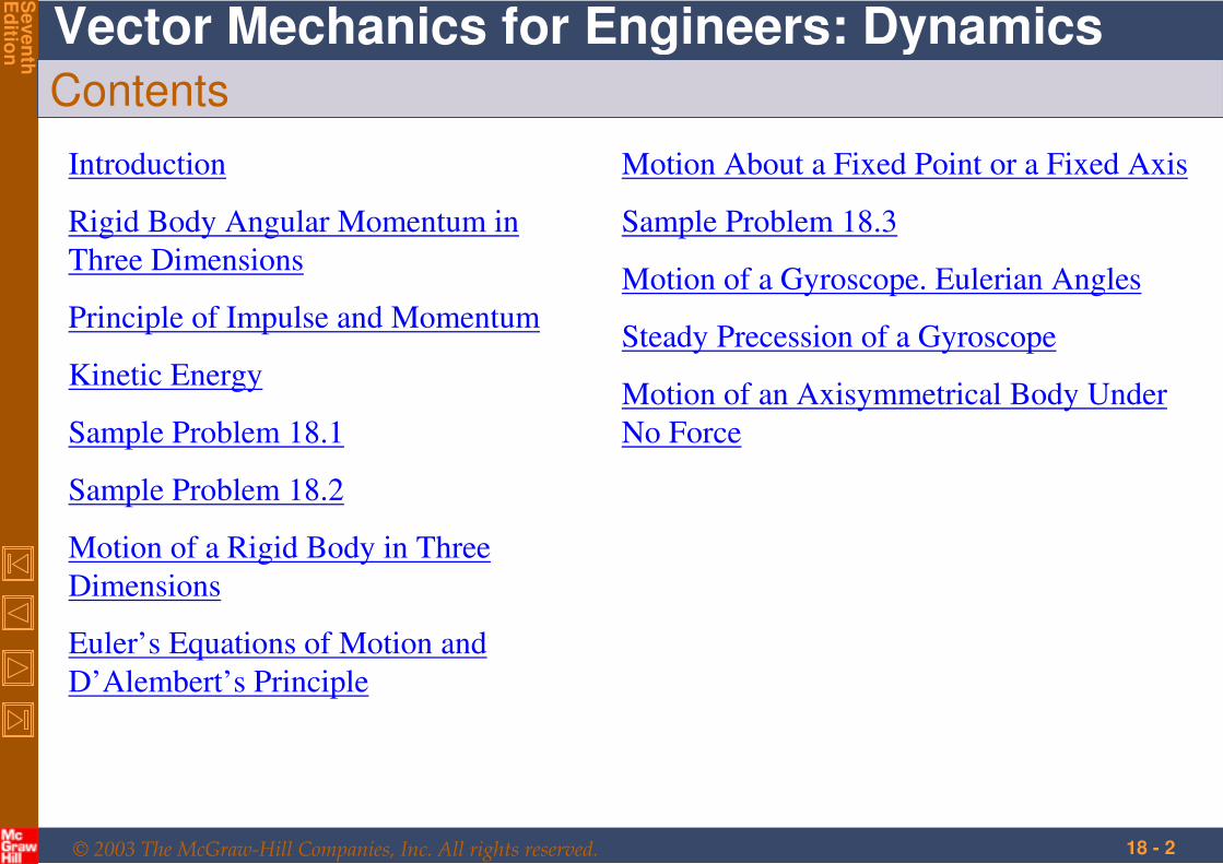
•The fundamental relations developed for
the plane motion of rigid bodies may also
be applied to the general motion of three
dimensional bodies.
•The relation ω
IH G =
which was used to determine the
angular momentum of a rigid slab is not valid
for general three dimensional bodies and
motion.
•The current chapter is concerned with
evaluation of the angular momentum and its
rate of change for three dimensional motion
and application to effective forces, the
impulse-momentum and the work-energy
principles.
© 2003 The McGraw-Hill Companies, Inc. All rights reserved.
Vector Mechanics for Engineers: Dynamics
Seven
thE
ditio
n
18 - 4
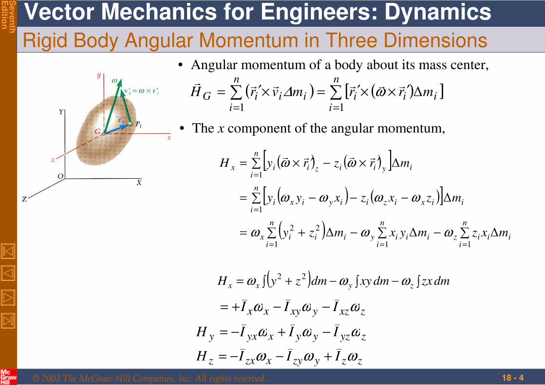
Rigid Body Angular Momentum in Three Dimensions• Angular momentum of a body about its mass center,
( ) ( )[ ]∑∑==
′××′=×′=n
iiii
n
iiiiG mrrmvrH
11
∆
ω∆
• The x component of the angular momentum,
( ) ( )[ ]
( ) ( )[ ]
( ) ∑−∑−∑ +=
∑ −−−=
∑ ′×−′×=
===
=
=
n
iiiiz
n
iiiiy
n
iiiix
n
iiixiziiyixi
n
iiyiiziix
mxzmyxmzy
mzxzxyy
mrzryH
111
22
1
1
∆∆∆
∆
∆
ωωω
ωωωω
ωω
( ) dmzxdmxydmzyH zyxx ∫−∫−∫ += ωωω 22
zxzyxyxx III ωωω −−+=
zzyzyxzxz
zyzyyxyxy
IIIH
IIIH
ωωω
ωωω
+−−=
−+−=
© 2003 The McGraw-Hill Companies, Inc. All rights reserved.
Vector Mechanics for Engineers: Dynamics
Seven
thE
ditio
n
18 - 5
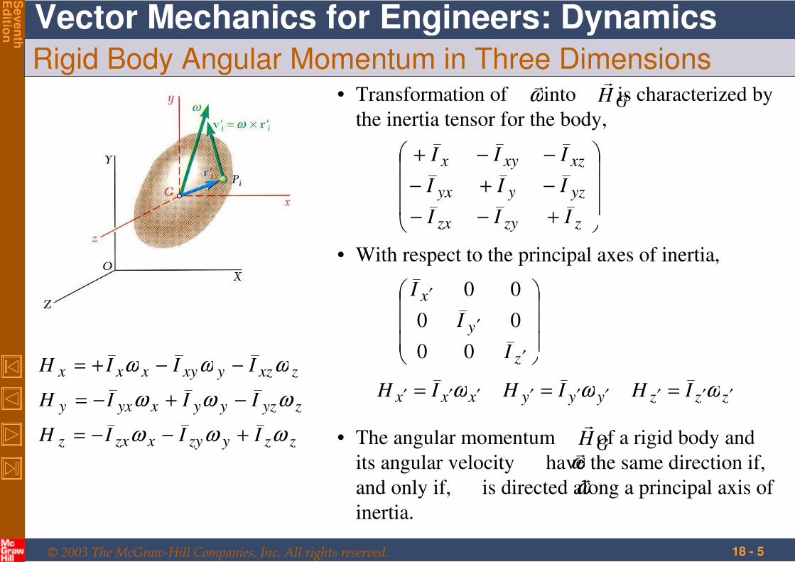
Rigid Body Angular Momentum in Three Dimensions
zzyzyxzxz
zyzyyxyxy
zxzyxyxxx
IIIH
IIIH
IIIH
ωωω
ωωω
ωωω
+−−=
−+−=
−−+=
• Transformation of into is characterized by
the inertia tensor for the body,
ω
GH
+−−
−+−
−−+
zzyzx
yzyyx
xzxyx
III
III
III
• With respect to the principal axes of inertia,
′
′
′
z
y
x
I
I
I
00
00
00
zzzyyyxxx IHIHIH ′′′′′′′′′ === ωωω
• The angular momentum of a rigid body and
its angular velocity have the same direction if,
and only if, is directed along a principal axis of
inertia.
GH
ω
ω
© 2003 The McGraw-Hill Companies, Inc. All rights reserved.
Vector Mechanics for Engineers: Dynamics
Seven
thE
ditio
n
18 - 6
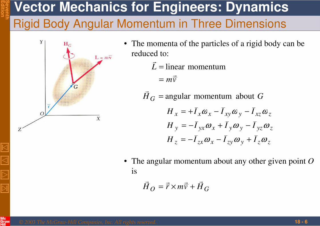
Rigid Body Angular Momentum in Three Dimensions
• The momenta of the particles of a rigid body can be
reduced to:
vm
L
=
= momentumlinear
GH G about momentumangular =
zzyzyxzxz
zyzyyxyxy
zxzyxyxxx
IIIH
IIIH
IIIH
ωωω
ωωω
ωωω
+−−=
−+−=
−−+=
• The angular momentum about any other given point O
is
GO HvmrH
+×=
© 2003 The McGraw-Hill Companies, Inc. All rights reserved.
Vector Mechanics for Engineers: Dynamics
Seven
thE
ditio
n
18 - 7
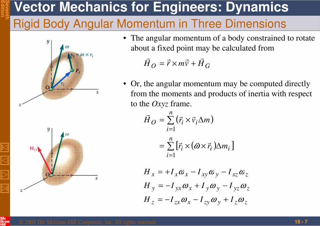
Rigid Body Angular Momentum in Three Dimensions• The angular momentum of a body constrained to rotate
about a fixed point may be calculated from
GO HvmrH
+×=
zzyzyxzxz
zyzyyxyxy
zxzyxyxxx
IIIH
IIIH
IIIH
ωωω
ωωω
ωωω
+−−=
−+−=
−−+=
• Or, the angular momentum may be computed directly
from the moments and products of inertia with respect
to the Oxyz frame.
( )
( )[ ]∑
∑
=
=
××=
×=
n
iiii
n
iiiO
mrr
mvrH
1
1
∆
∆
ω

© 2003 The McGraw-Hill Companies, Inc. All rights reserved.
Vector Mechanics for Engineers: Dynamics
Seven
thE
ditio
n
18 - 8
Principle of Impulse and Momentum
• The principle of impulse and momentum can be applied directly to the three-
dimensional motion of a rigid body,
Syst Momenta1 + Syst Ext Imp1-2 = Syst Momenta2
• The free-body diagram equation is used to develop component and
moment equations.
• For bodies rotating about a fixed point, eliminate the impulse of the
reactions at O by writing equation for moments of momenta and impulses
about O.
© 2003 The McGraw-Hill Companies, Inc. All rights reserved.
Vector Mechanics for Engineers: Dynamics
Seven
thE
ditio
n
18 - 9
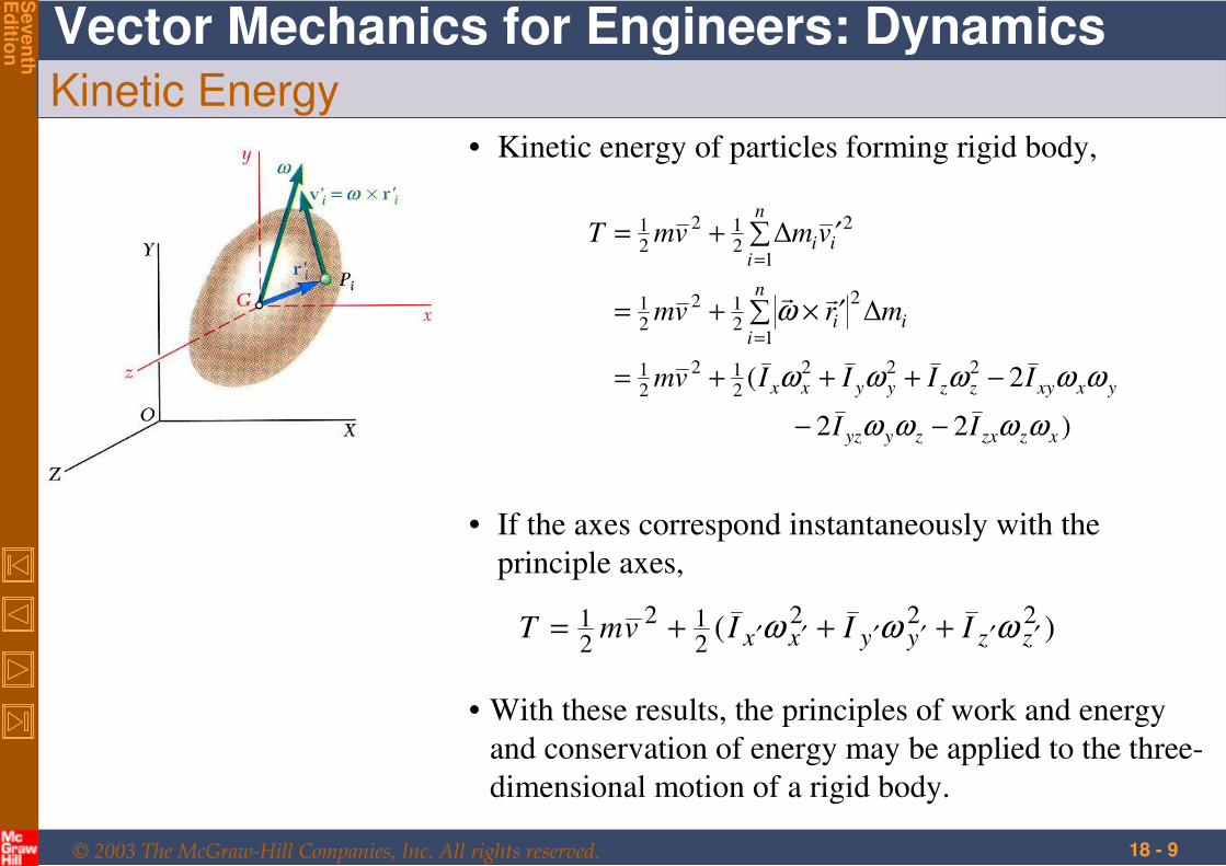
Kinetic Energy• Kinetic energy of particles forming rigid body,
)22
2(
∆
∆
222
212
21
1
2
212
21
1
2
212
21
xzzxzyyz
yxxyzzyyxx
n
iii
n
iii
II
IIIIvm
mrvm
vmvmT
ωωωω
ωωωωω
ω
−−
−+++=
∑ ′×+=
∑ ′+=
=
=
• If the axes correspond instantaneously with the
principle axes,
)( 222212
21
zzyyxx IIIvmT ′′′′′′ +++= ωωω
• With these results, the principles of work and energy
and conservation of energy may be applied to the three-
dimensional motion of a rigid body.
© 2003 The McGraw-Hill Companies, Inc. All rights reserved.
Vector Mechanics for Engineers: Dynamics
Seven
thE
ditio
n
18 - 10
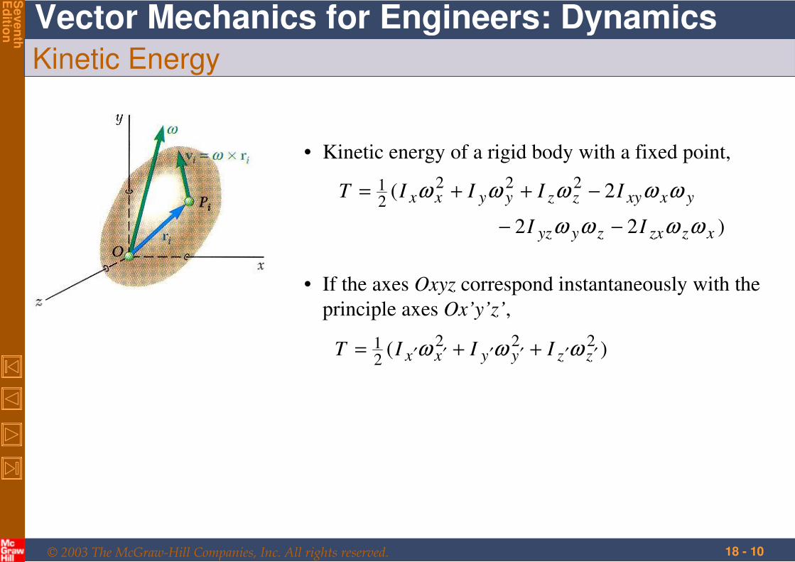
Kinetic Energy
• Kinetic energy of a rigid body with a fixed point,
)22
2( 22221
xzzxzyyz
yxxyzzyyxx
II
IIIIT
ωωωω
ωωωωω
−−
−++=
• If the axes Oxyz correspond instantaneously with the
principle axes Ox’y’z’,
)( 22221
zzyyxx IIIT ′′′′′′ ++= ωωω
© 2003 The McGraw-Hill Companies, Inc. All rights reserved.
Vector Mechanics for Engineers: Dynamics
Seven
thE
ditio
n
18 - 11
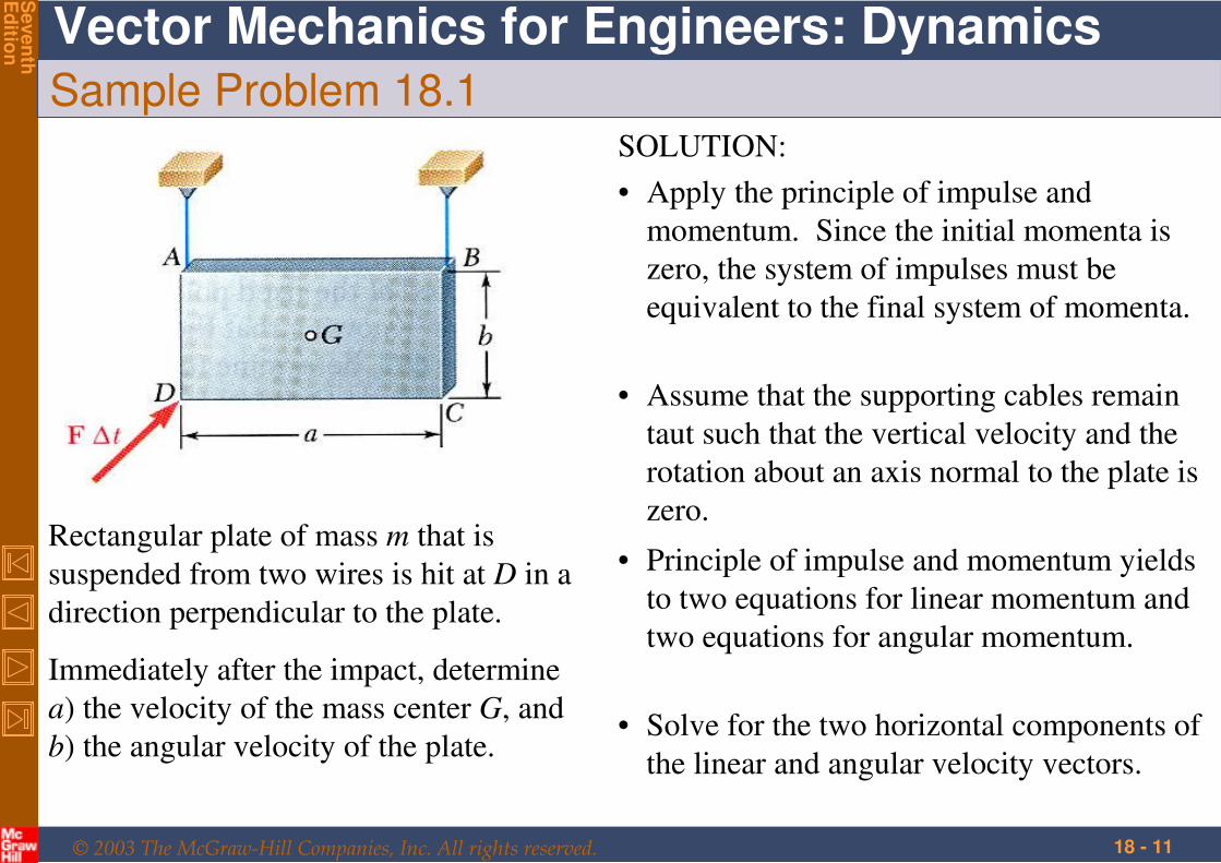
Sample Problem 18.1
Rectangular plate of mass m that is
suspended from two wires is hit at D in a
direction perpendicular to the plate.
Immediately after the impact, determine
a) the velocity of the mass center G, and
b) the angular velocity of the plate.
SOLUTION:
• Apply the principle of impulse and
momentum. Since the initial momenta is
zero, the system of impulses must be
equivalent to the final system of momenta.
• Assume that the supporting cables remain
taut such that the vertical velocity and the
rotation about an axis normal to the plate is
zero.
• Principle of impulse and momentum yields
to two equations for linear momentum and
two equations for angular momentum.
• Solve for the two horizontal components of
the linear and angular velocity vectors.
© 2003 The McGraw-Hill Companies, Inc. All rights reserved.
Vector Mechanics for Engineers: Dynamics
Seven
thE
ditio
n
18 - 12
Sample Problem 18.1
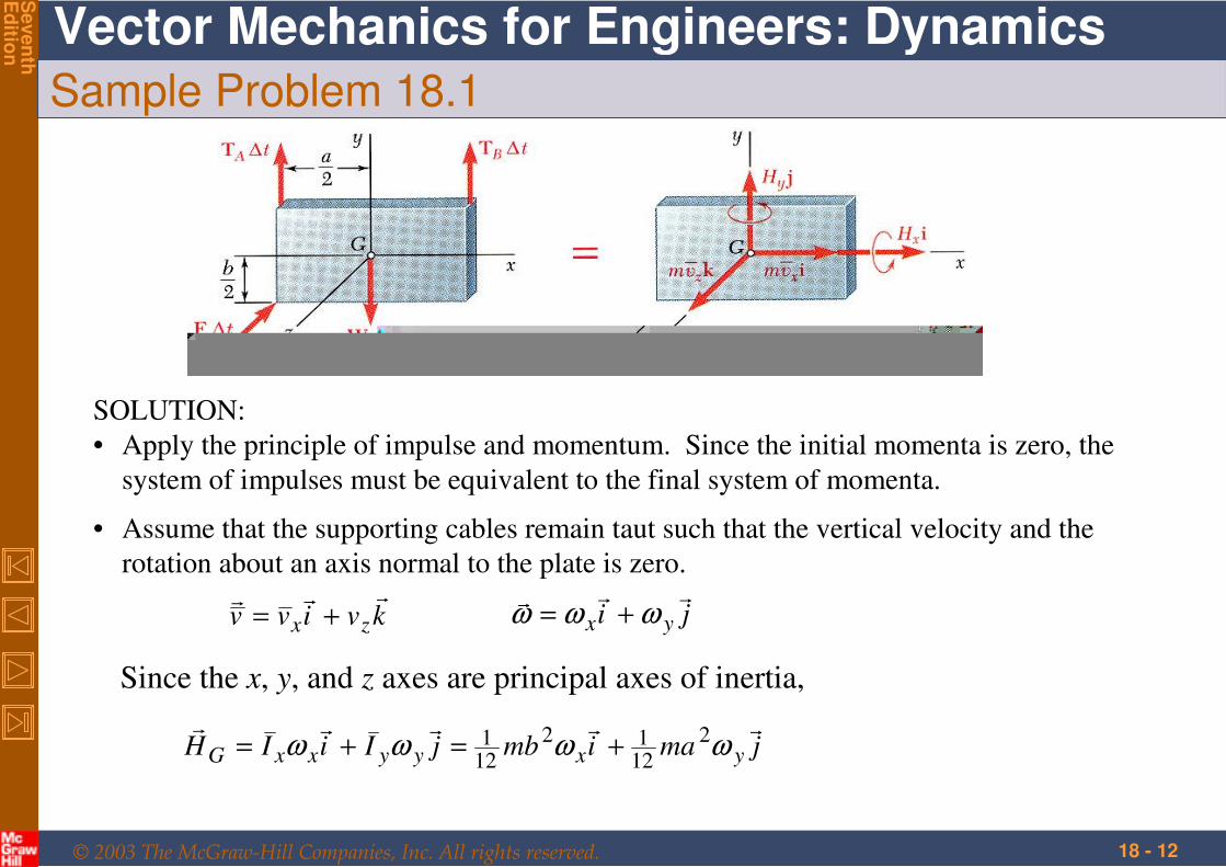
SOLUTION:
• Apply the principle of impulse and momentum. Since the initial momenta is zero, the
system of impulses must be equivalent to the final system of momenta.
• Assume that the supporting cables remain taut such that the vertical velocity and the
rotation about an axis normal to the plate is zero.
kvivv zx
+= ji yx
ωωω +=
Since the x, y, and z axes are principal axes of inertia,
jmaimbjIiIH yxyyxxG
ωωωω 2
1212
121 +=+=
© 2003 The McGraw-Hill Companies, Inc. All rights reserved.
Vector Mechanics for Engineers: Dynamics
Seven
thE
ditio
n
18 - 13
Sample Problem 18.1
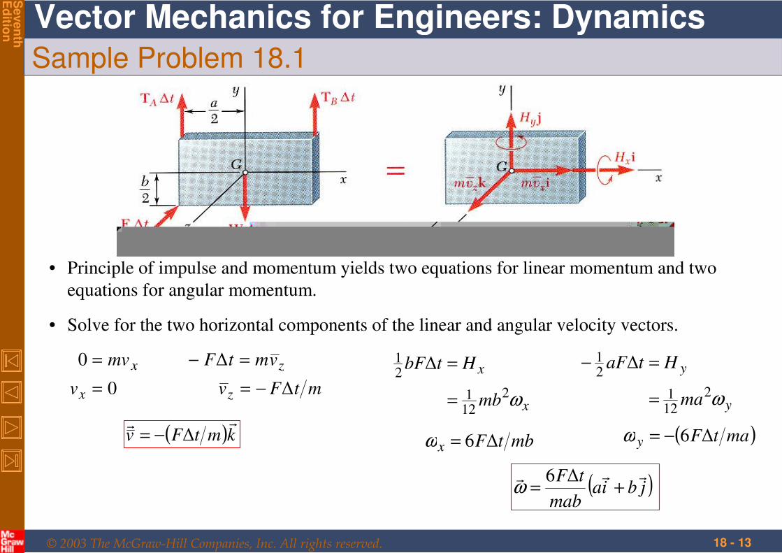
• Principle of impulse and momentum yields two equations for linear momentum and two
equations for angular momentum.
• Solve for the two horizontal components of the linear and angular velocity vectors.
xmv=0
0=xv
zvmtF =− ∆
mtFvz ∆−=
( )kmtFv
∆−=
x
x
mb
HtbF
ω2
121
21
∆
=
=
mbtFx ∆6=ω
y
y
ma
HtaF
ω2
121
21
∆
=
=−
( )matFy ∆6−=ω
( )jbiamab
tF +=
∆6ω
© 2003 The McGraw-Hill Companies, Inc. All rights reserved.
Vector Mechanics for Engineers: Dynamics
Seven
thE
ditio
n
18 - 14
Sample Problem 18.1
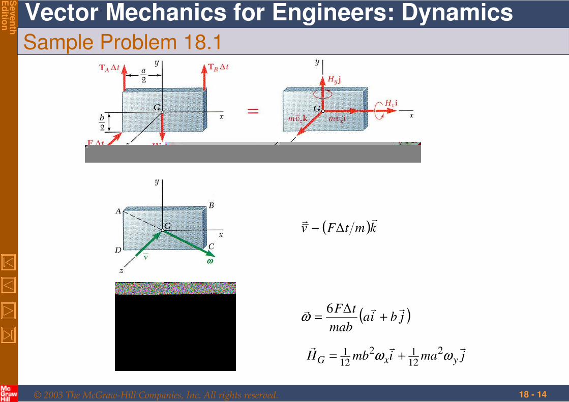
( )kmtFv
∆−
( )jbiamab
tF +=
∆6ω
jmaimbH yxG
ωω 2
1212
121 +=
© 2003 The McGraw-Hill Companies, Inc. All rights reserved.
Vector Mechanics for Engineers: Dynamics
Seven
thE
ditio
n
18 - 15
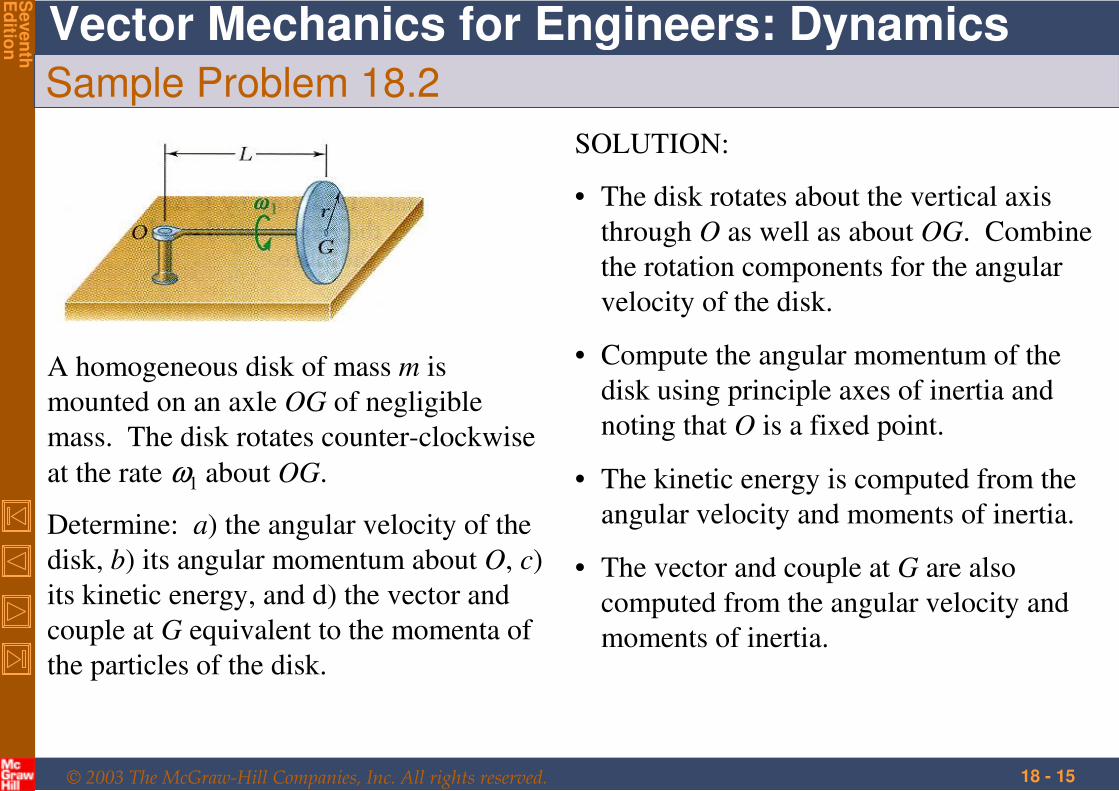
Sample Problem 18.2
A homogeneous disk of mass m is
mounted on an axle OG of negligible
mass. The disk rotates counter-clockwise
at the rate ω1 about OG.
Determine: a) the angular velocity of the
disk, b) its angular momentum about O, c)
its kinetic energy, and d) the vector and
couple at G equivalent to the momenta of
the particles of the disk.
SOLUTION:
• The disk rotates about the vertical axis
through O as well as about OG. Combine
the rotation components for the angular
velocity of the disk.
• Compute the angular momentum of the
disk using principle axes of inertia and
noting that O is a fixed point.
• The kinetic energy is computed from the
angular velocity and moments of inertia.
• The vector and couple at G are also
computed from the angular velocity and
moments of inertia.
© 2003 The McGraw-Hill Companies, Inc. All rights reserved.
Vector Mechanics for Engineers: Dynamics
Seven
thE
ditio
n
18 - 16
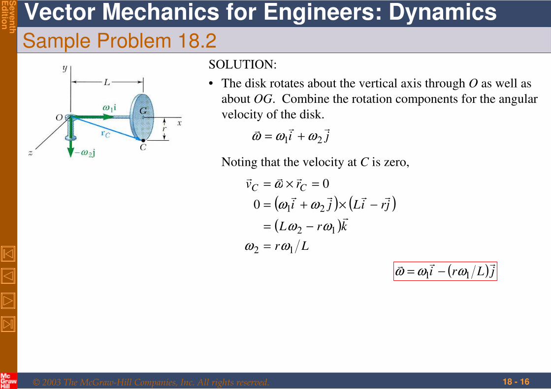
Sample Problem 18.2SOLUTION:
• The disk rotates about the vertical axis through O as well as
about OG. Combine the rotation components for the angular
velocity of the disk.
ji
21 ωωω +=
Noting that the velocity at C is zero,
( ) ( )( )
Lr
krL
jriLji
rv CC
12
12
210
0
ωω
ωω
ωω
ω
=
−=
−×+=
=×=
( ) jLri
11 ωωω −=
© 2003 The McGraw-Hill Companies, Inc. All rights reserved.
Vector Mechanics for Engineers: Dynamics
Seven
thE
ditio
n
18 - 17
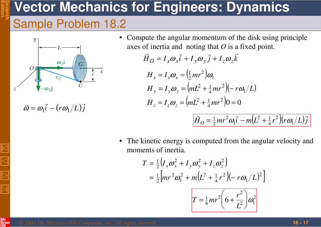
Sample Problem 18.2• Compute the angular momentum of the disk using principle
axes of inertia and noting that O is a fixed point.
( ) jLri
11 ωωω −=
kIjIiIH zzyyxxO
ωωω ++=
( )( )( )
( ) 002
412
12
412
12
21
=+==
−+==
==
mrmLIH
LrmrmLIH
mrIH
zzz
yyy
xxx
ω
ωω
ωω
( )( ) jLrrLmimrHO
12
412
12
21 ωω +−=
• The kinetic energy is computed from the angular velocity and
moments of inertia.
( )( )( )[ ]2
12
4122
12
21
222
21
LrrLmmr
IIIT zzyyxx
ωω
ωωω
−++=
++=
212
22
81 6 ω
+=
L
rmrT
© 2003 The McGraw-Hill Companies, Inc. All rights reserved.
Vector Mechanics for Engineers: Dynamics
Seven
thE
ditio
n
18 - 18
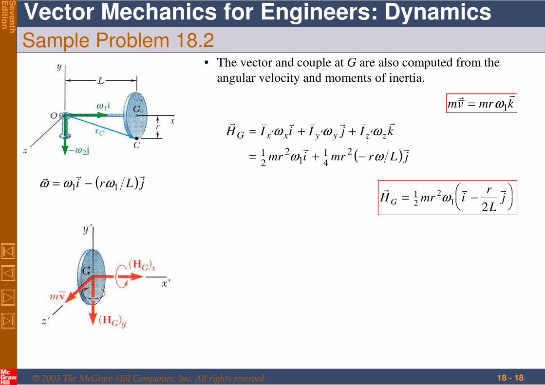
Sample Problem 18.2
( ) jLri
11 ωωω −=
• The vector and couple at G are also computed from the
angular velocity and moments of inertia.
kmrvm
1ω=
( ) jLrmrimr
kIjIiIH zzyyxxG
ωω
ωωω
−+=
++= ′′′
2
41
12
21
−= jL
rimrH G
21
2
21 ω
© 2003 The McGraw-Hill Companies, Inc. All rights reserved.
Vector Mechanics for Engineers: Dynamics
Seven
thE
ditio
n
18 - 19
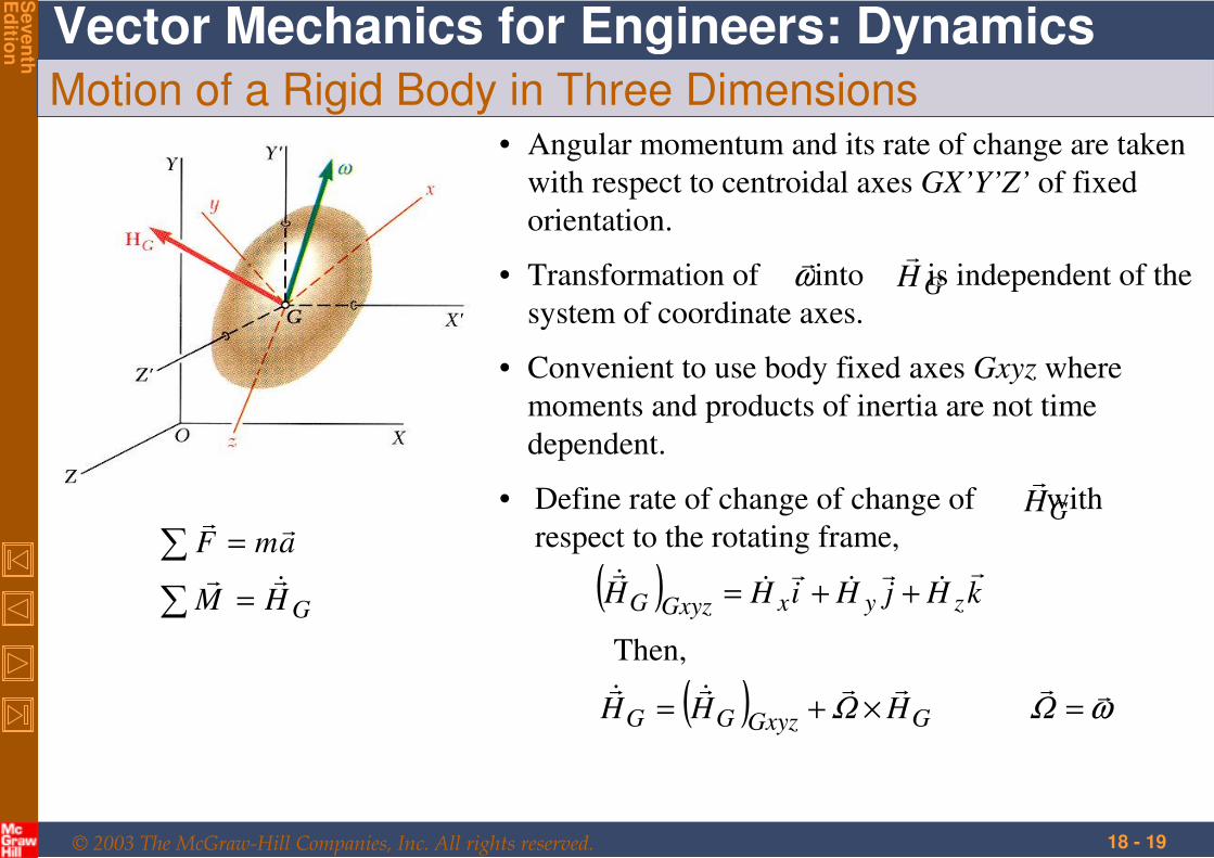
Motion of a Rigid Body in Three Dimensions
GHM
amF
=
=
∑
∑
• Angular momentum and its rate of change are taken
with respect to centroidal axes GX’Y’Z’ of fixed
orientation.
• Convenient to use body fixed axes Gxyz where
moments and products of inertia are not time
dependent.
• Transformation of into is independent of the
system of coordinate axes.
ω
GH
• Define rate of change of change of with
respect to the rotating frame,GH
( ) kHjHiHH zyxGxyzG
++=
Then,
( ) ωΩΩ
=×+= GGxyzGG HHH
© 2003 The McGraw-Hill Companies, Inc. All rights reserved.
Vector Mechanics for Engineers: Dynamics
Seven
thE
ditio
n
18 - 20
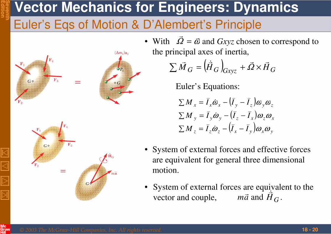
Euler’s Eqs of Motion & D’Alembert’s Principle
( ) GGxyzGG HHM
×+=∑ Ω
• With and Gxyz chosen to correspond to
the principal axes of inertia,
ωΩ
=
( )( )
( ) yxyxzzz
xzxzyyy
zyzyxxx
IIIM
IIIM
IIIM
ωωω
ωωω
ωωω
−−=∑
−−=∑
−−=∑
Euler’s Equations:
• System of external forces and effective forces
are equivalent for general three dimensional
motion.
• System of external forces are equivalent to the
vector and couple, . and GHam
© 2003 The McGraw-Hill Companies, Inc. All rights reserved.
Vector Mechanics for Engineers: Dynamics
Seven
thE
ditio
n
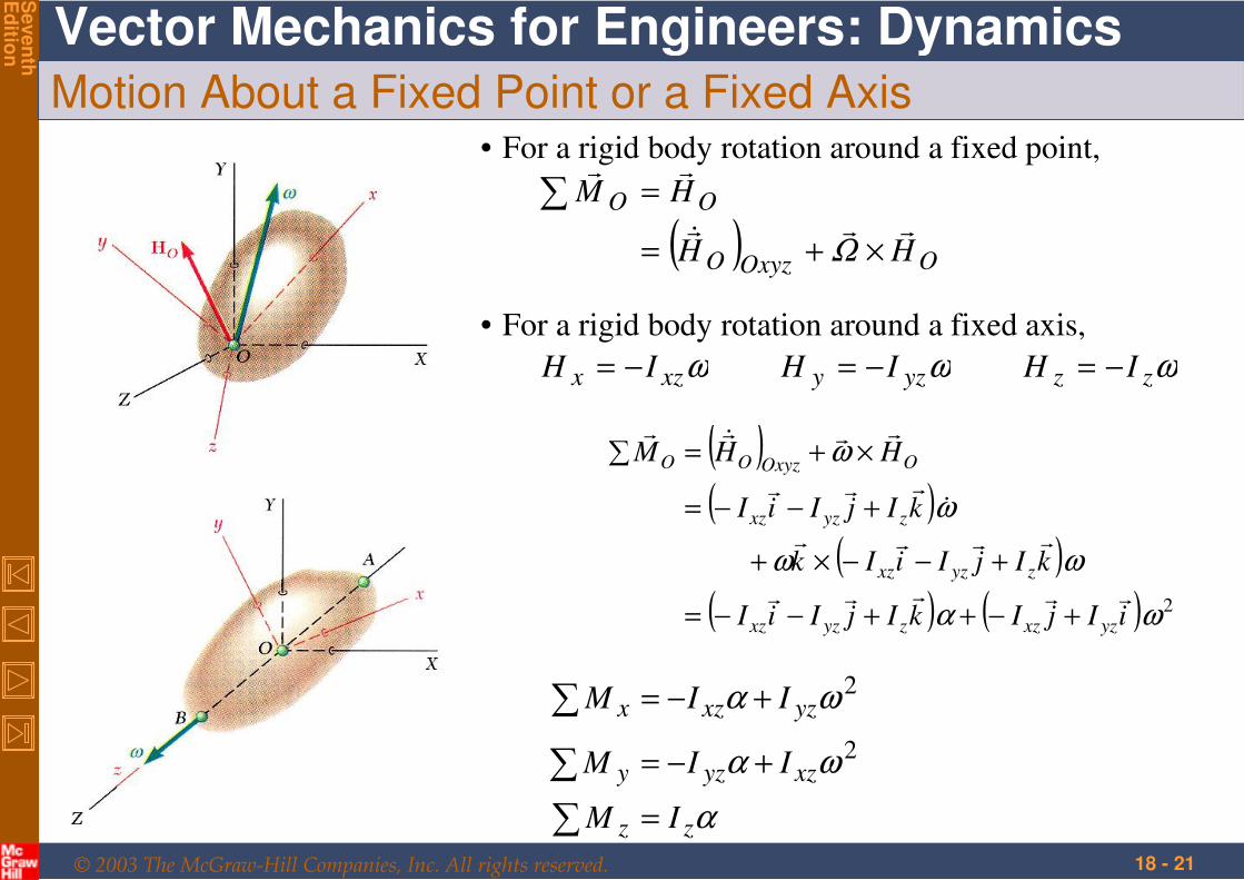
18 - 21
Motion About a Fixed Point or a Fixed Axis• For a rigid body rotation around a fixed point,
( ) OOxyzO
OO
HH
HM
×+=
=∑
Ω
• For a rigid body rotation around a fixed axis,
ωωω zzyzyxzx IHIHIH −=−=−=
( )( )
( )( ) ( ) 2ωα
ωω
ω
ω
iIjIkIjIiI
kIjIiIk
kIjIiI
HHM
yzxzzyzxz
zyzxz
zyzxz
OOxyzOO
+−++−−=
+−−×+
+−−=
×+=∑
α
ωα
ωα
zz
xzyzy
yzxzx
IM
IIM
IIM
=
+−=
+−=
∑
∑
∑2
2
© 2003 The McGraw-Hill Companies, Inc. All rights reserved.
Vector Mechanics for Engineers: Dynamics
Seven
thE
ditio
n
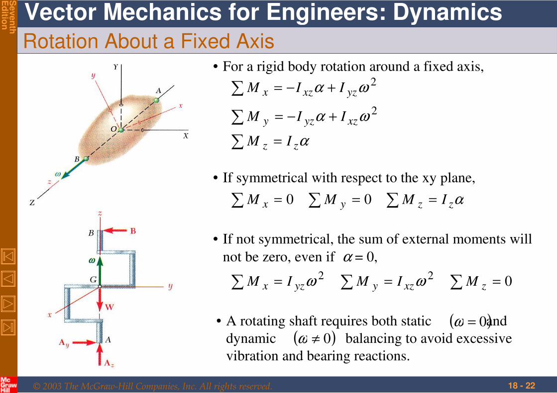
18 - 22
Rotation About a Fixed Axis
α
ωα
ωα
zz
xzyzy
yzxzx
IM
IIM
IIM
=
+−=
+−=
∑
∑
∑2
2
• For a rigid body rotation around a fixed axis,
• If symmetrical with respect to the xy plane,
αzzyx IMMM === ∑∑∑ 00
• If not symmetrical, the sum of external moments will
not be zero, even if α = 0,
022 === ∑∑∑ zxzyyzx MIMIM ωω
• A rotating shaft requires both static and
dynamic balancing to avoid excessive
vibration and bearing reactions.
( )0=ω( )0≠ω
© 2003 The McGraw-Hill Companies, Inc. All rights reserved.
Vector Mechanics for Engineers: Dynamics
Seven
thE
ditio
n
18 - 23
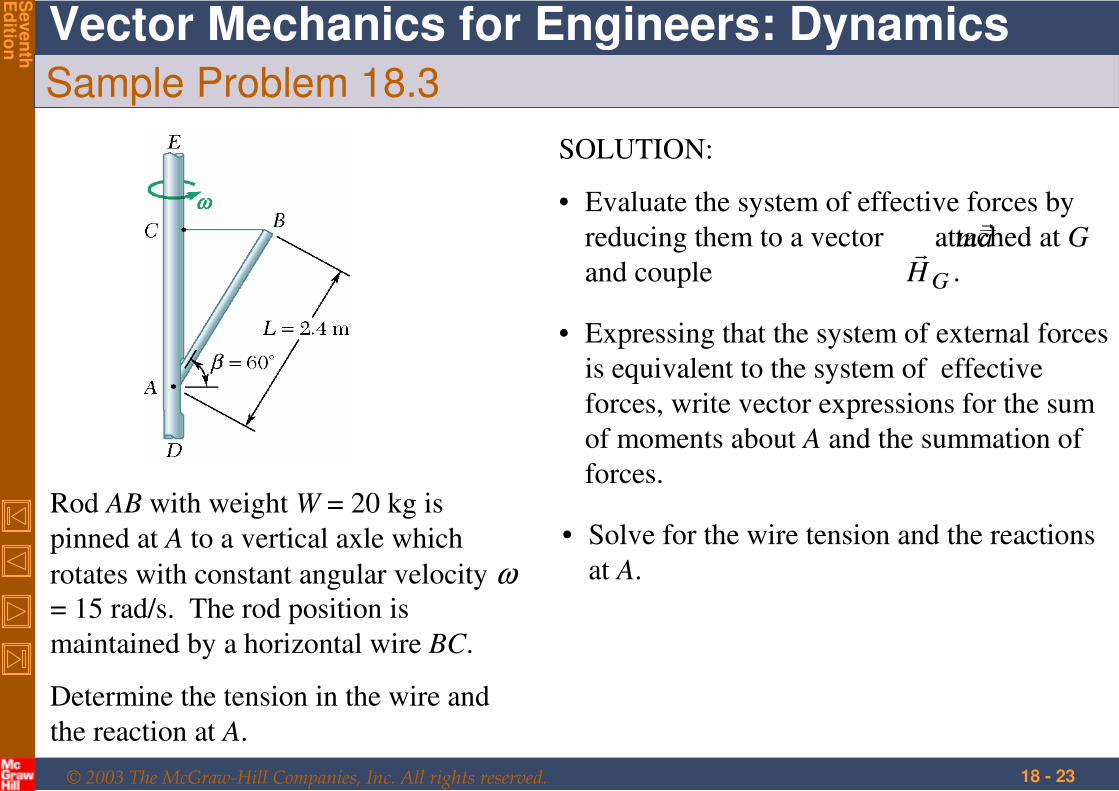
Sample Problem 18.3
Rod AB with weight W = 20 kg is
pinned at A to a vertical axle which
rotates with constant angular velocity ω= 15 rad/s. The rod position is
maintained by a horizontal wire BC.
Determine the tension in the wire and
the reaction at A.
• Expressing that the system of external forces
is equivalent to the system of effective
forces, write vector expressions for the sum
of moments about A and the summation of
forces.
• Solve for the wire tension and the reactions
at A.
SOLUTION:
• Evaluate the system of effective forces by
reducing them to a vector attached at G
and couple
am
.GH
© 2003 The McGraw-Hill Companies, Inc. All rights reserved.
Vector Mechanics for Engineers: Dynamics
Seven
thE
ditio
n
18 - 24
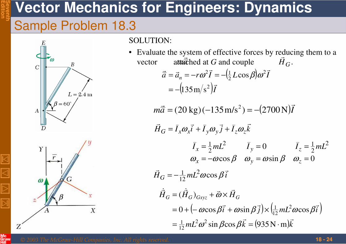
Sample Problem 18.3SOLUTION:
• Evaluate the system of effective forces by reducing them to a
vector attached at G and coupleam
.GH
( )( )I
ILIraa n
2
2
212
sm135
cos
−=
−=−== ωβω
( )Iam
N2700)s/m135()kg20(2 −=−=
kIjIiIH zzyyxxG
ωωω ++=
0sincos
0 2
212
21
==−=
===
zyx
zyx mLIImLI
ωβωωβωω
imLHG
βω cos2
121−=
( ) ( )( )kkmL
imLji
HHH GGxyzGG
mN935cossin
cossincos0
)(
22
121
2
121
⋅==
×+−+=
×+=
ββω
βωβωβω
ω
© 2003 The McGraw-Hill Companies, Inc. All rights reserved.
Vector Mechanics for Engineers: Dynamics
Seven
thE
ditio
n
18 - 25
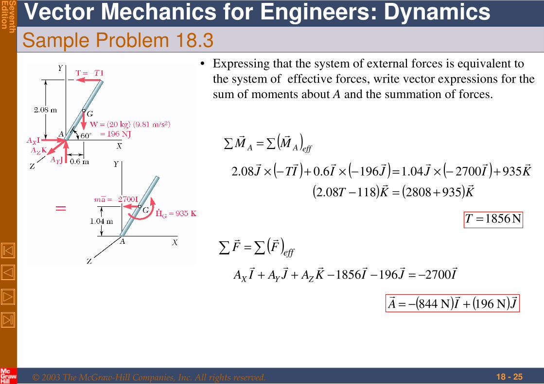
Sample Problem 18.3• Expressing that the system of external forces is equivalent to
the system of effective forces, write vector expressions for the
sum of moments about A and the summation of forces.
( )effAA MM ∑=∑
( ) ( ) ( )( ) ( )KKT
KIJJIITJ
935280811808.2
935270004.11966.008.2
+=−
+−×=−×+−×
N1856=T
( )eff
FF ∑∑ =
IJIKAJAIA ZYX
27001961856 −=−−++
( ) ( )JIA
N 961N 448 +−=
© 2003 The McGraw-Hill Companies, Inc. All rights reserved.
Vector Mechanics for Engineers: Dynamics
Seven
thE
ditio
n
18 - 26
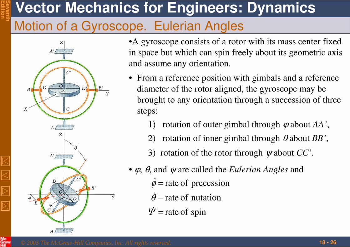
Motion of a Gyroscope. Eulerian Angles•A gyroscope consists of a rotor with its mass center fixed
in space but which can spin freely about its geometric axis
and assume any orientation.
• From a reference position with gimbals and a reference
diameter of the rotor aligned, the gyroscope may be
brought to any orientation through a succession of three
steps:
1) rotation of outer gimbal through ϕ about AA’,
3) rotation of the rotor through ψ about CC’.
• ϕ, θ, and ψ are called the Eulerian Angles and
spin of rate
nutation of rate
precession of rate
=
=
=
Ψ
θ
φ
2) rotation of inner gimbal through θ about BB’,
© 2003 The McGraw-Hill Companies, Inc. All rights reserved.
Vector Mechanics for Engineers: Dynamics
Seven
thE
ditio
n
18 - 27
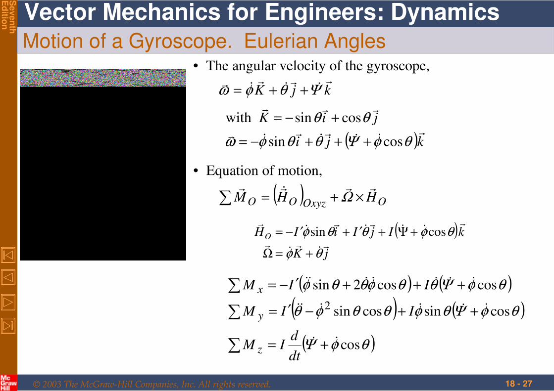
Motion of a Gyroscope. Eulerian Angles• The angular velocity of the gyroscope,
kjK
Ψθφω ++=
( )kji
jiK
θφΨθθφω
θθ
cossin
cossinwith
+++−=
+−=
• Equation of motion,
( ) OOxyzOO HHM
×+=∑ Ω
( )jK
kIjIiIHO
θφ
θφθθφ
+=Ω
+Ψ+′+′−= cossin
( ) ( )
( ) ( )
( )θφΨ
θφΨθφθθφθ
θφΨθθφθθφ
cos
cossincossin
coscos2sin
2
+=
++−′=
+++′−=
∑
∑
∑
dt
dIM
IIM
IIM
z
y
x

© 2003 The McGraw-Hill Companies, Inc. All rights reserved.
Vector Mechanics for Engineers: Dynamics
Seven
thE
ditio
n
18 - 28
Steady Precession of a Gyroscope
Steady precession,
constant are ,, ψφθ
ki
kIiIH
ki
zO
z
θφθφΩ
ωθφ
ωθφω
cossin
sin
sin
+−=
+′−=
+−=
( ) jII
HM
z
OO
θφθφω sincos′−=
×Ω=∑
Couple is applied about an axis
perpendicular to the precession
and spin axes
When the precession and spin axis
are at a right angle,
jIM O
φΨ
θ
=
°=
∑
90
Gyroscope will precess about an
axis perpendicular to both the spin
axis and couple axis.
© 2003 The McGraw-Hill Companies, Inc. All rights reserved.
Vector Mechanics for Engineers: Dynamics
Seven
thE
ditio
n
18 - 29
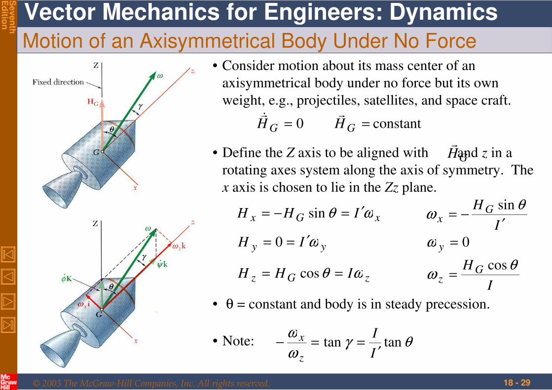
Motion of an Axisymmetrical Body Under No Force• Consider motion about its mass center of an
axisymmetrical body under no force but its own
weight, e.g., projectiles, satellites, and space craft.
constant 0 == GG HH
• Define the Z axis to be aligned with and z in a
rotating axes system along the axis of symmetry. The
x axis is chosen to lie in the Zz plane.
GH
xGx IHH ωθ ′=−= sinI
H Gx ′
−=θ
ωsin
yy IH ω′== 0 0=yω
zGz IHH ωθ == cosI
H Gz
θω
cos=
• θ = constant and body is in steady precession.
• Note: θγω
ωtantan
I
I
z
x
′==−
© 2003 The McGraw-Hill Companies, Inc. All rights reserved.
Vector Mechanics for Engineers: Dynamics
Seven
thE
ditio
n
18 - 30
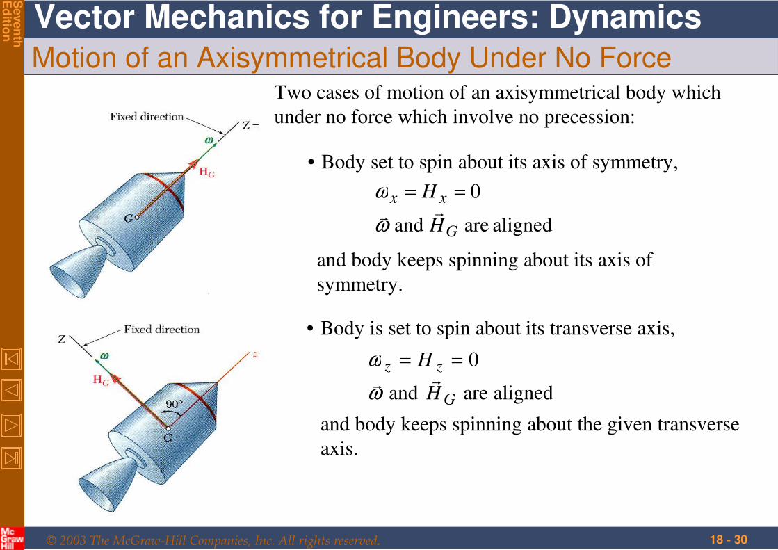
Motion of an Axisymmetrical Body Under No ForceTwo cases of motion of an axisymmetrical body which
under no force which involve no precession:
• Body set to spin about its axis of symmetry,
aligned are and
0
G
xx
H
H
ω
ω ==
and body keeps spinning about its axis of
symmetry.
• Body is set to spin about its transverse axis,
aligned are and
0
G
zz
H
H
ω
ω ==
and body keeps spinning about the given transverse
axis.
© 2003 The McGraw-Hill Companies, Inc. All rights reserved.
Vector Mechanics for Engineers: Dynamics
Seven
thE
ditio
n
18 - 31
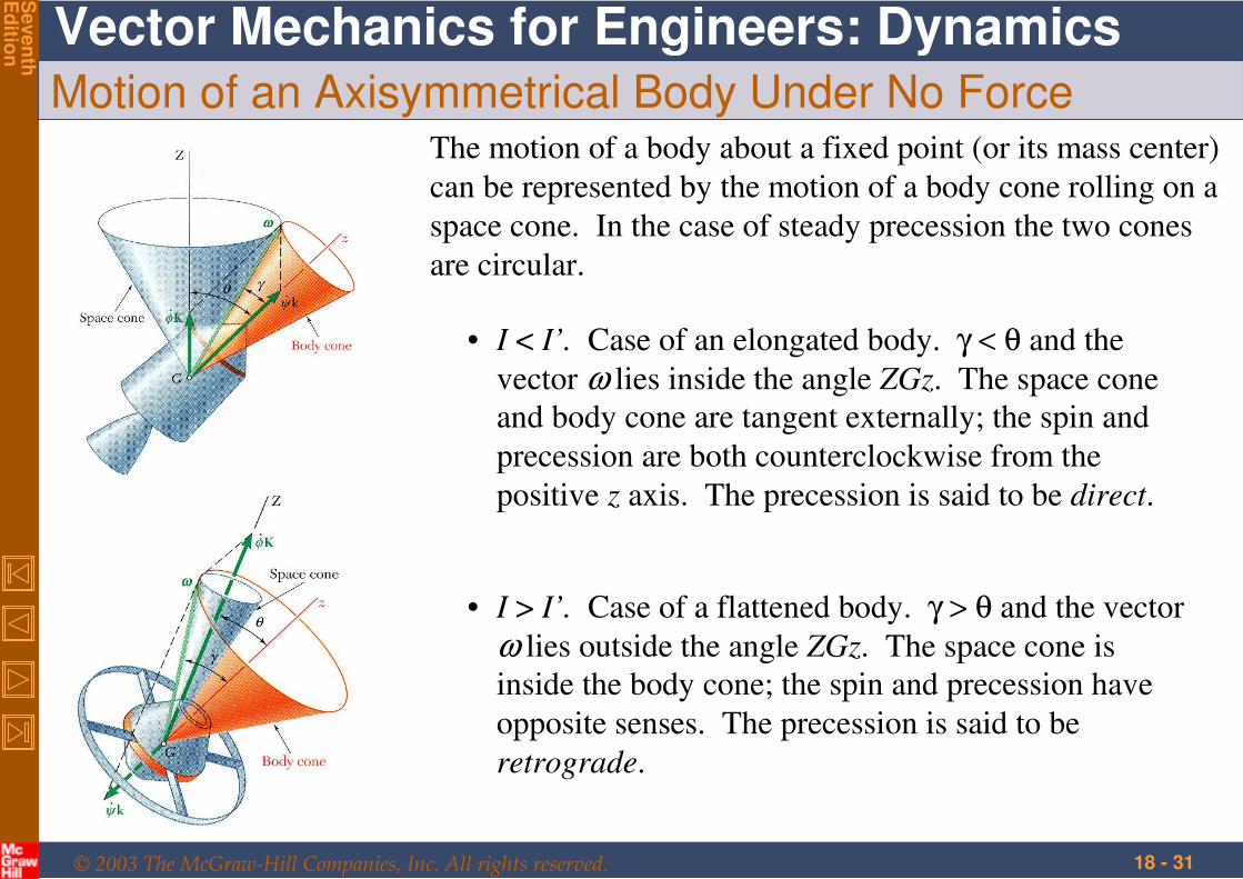
Motion of an Axisymmetrical Body Under No ForceThe motion of a body about a fixed point (or its mass center)
can be represented by the motion of a body cone rolling on a
space cone. In the case of steady precession the two cones
are circular.
• I < I’. Case of an elongated body. γ < θ and the
vector ω lies inside the angle ZGz. The space cone
and body cone are tangent externally; the spin and
precession are both counterclockwise from the
positive z axis. The precession is said to be direct.
• I > I’. Case of a flattened body. γ > θ and the vector
ω lies outside the angle ZGz. The space cone is
inside the body cone; the spin and precession have
opposite senses. The precession is said to be
retrograde.


![Chap18[1] the Statement of Cashflows](https://img.pdfslide.net/doc/110x75/55cf9942550346d0339c7445/chap181-the-statement-of-cashflows.jpg)