Embed Size (px)
DESCRIPTION
nota psas
Citation preview

6.0 AUDIO AMPLIFIER
Slide by Mohd Fairose

OBJECTIVE Understand principle of simple Audio
Amplifier Test the functionality of Audio Amplifier Troubleshoot simple Audio Amplifier Understand the principle of PA system Troubleshoot PA system unit
Fai’11
Menu Next

6.0 AUDIO AMPLIFIER MENU
EXIT
AUDIO AMP VIDEO1AUDIO AMP VIDEO2PRINCIPLE OF AUDIO AMPLIFIER
AUDIO SYSTEM BLOCK DIAGRAMSCHEMATIC DIAGRAM OF AUDIO AMPLIFIERTEST THE FUNCTIONALITY
INPUT AND OUTPUTWAVEFORMTROUBLESHOOT AUDIO AMPLIFIERPRINCIPLE OF PA SYSTEM

PRINCIPLE OF SIMPLE AUDIO AMPLIFIER. Definition electronic amplifier that amplifies low-
power audio signals
between 20 - 20 000 Hz (level suitable for driving loudspeakers)
final stage in a typical audio playback chain.
Menu Next
Fai’11

OBE Exercise
Discus in your group of what is the application of audio amplifier
NextMenu
Fai’11

1
3
2Driver Amplifier
Audio / Power Amplifier
Pre Amplifier
I/P Transducer ex: mic, tape head etc.
Tone control – Bass, Volume, Treble
SpeakerAUDIO SYSTEM BLOCK DIAGRAM
NextMenu
Fai’11

Transducer
converts one type of energy to another
energy types include electrical, mechanical, electromagnetic (including light), chemical and etc
CD/DVD Player, Tape, Radio AM/FM, Microphone, MP3 Player, IPod and etc
FUNCTION OF EACH BLOCKNextMenu
Fai’11

Pre Amplifier prepares a small electrical signal for further
amplification or processing
often placed close to the sensor to reduce the effects of noise and interference
used to boost the signal strength without significantly degrading the signal-to-noise ratio (SNR)
NextMenu
Fai’11

Tone control – Bass, Volume, Treble
equalize the sound produced on the speakers to match the original
Consist of Bass – low pass filter, Treble (high pass filter) and Volume (regulator)
basic principle of setting the tone is obtained by setting the value of R / C resonator in the filter circuit.
NextMenu
Fai’11

Driver Amplifier
amplify signal from tone control
phase splitter & drive the power amplifier to operate.
NextMenu
Fai’11

Audio/Power Amplifier
amplifying the regulatory signal from the tone circuit
vibrate the speaker membrane
main requirement is a low output impedance of 4-16 ohms and high efficiency.
NextMenu
Fai’11

Speaker converts electrical signals into sound
signals
divided into three, namely the woofer (bass), Squeaker (middle), and the tweeter (high),subwoofer able to reproduce the audio signal below the woofer
Impedance of 4 ohm speakers, 8 ohms and 16 ohms.
NextMenu
Fai’11

OBE Exercise
Discus in your group of what is the example of transducer What is the different between Bass
sound and Treble sound.
NextMenu
Fai’11

SCHEMATIC DIAGRAM OF SIMPLE AUDIO AMPLIFIERPre- amp
uPC1032H low noise preamplifier
NextMenu
Fai’11

When we want to use the signals from the tape head, magnetic needle, or a microphone as the input signal, then it must be through a network of small-signal amplifier
all input signal frequencies will be reinforced with multiples of the same magnitude.
In Figure 7.1 below shows a simple network of pre-amplifier. Equalizer network is determined by the values of R1, R2, R3, C2, C3, and C4 to adjust the value of Gain,A.
NextMenu
Fai’11
Tone control
NextMenu
Fai’11

Before the tone control circuit input, there is a transistor amplifier arranged with collector-base configuration feedback
Balance control located at the input transistors, the linear P2.
Bass voice is controlled by P3, whereas the treble voice operated by P4.
NextMenu
Fai’11

Power amplifier (IC TA7230A)
NextMenu
Fai’11
R14, R15, C24, and C25 at the input is a low pass filter network
C15 and C18 are used for input signal and arranged to prevent the voltage at on pins 3 and 8
C16 and C17 is a noun coefficients to the ac signal so that low-frequency sounds are not muted
NextMenu
Fai’11

C19 is a bypass filter to the AF amplifier ripple voltage to it
Amplifier output is taken from pins 2 and 10 through capacitors C22 and C23, while power supply is supplied to the pin1 and 8.
NextMenu
Fai’11

Power amplifier (IC LM386)
Bypass cap-avoid humming
Lowpass filter-adjust Bass
Coupling cap-block DC voltage (DC voltage can heat up and burn the speaker)
C1
C4
C3
C2
R1
R2

C1 and C2 known as bypass capacitor. It always applied at the voltage supplied to avoid humming noise.
C3 and R2 known as lowpass filter. It only let the low frequency pass. This also applied as a Bass sound controller.
C1 known as coupling capacitor. It block DC Voltage and only let AC Voltage through. DC can heat up and burn the speaker.

Power amplifier (IC LM386) operationV+
V-
npn
pnp

Power supply
NextMenu
Fai’11

transformer center tap is used with the rating of 1A, 12-0-12 volts.
Diodes D1 and D2 serve as liters rectifier converts ac voltage the voltage dc and filtered by capacitor C26.
NextMenu
Fai’11

C26 is supplied to the positive point of enforcement, at which point VCC.
Supply power to the network and pre-amplifier tone controls taken from points A and B after the voltage through the filter gyrator R17, C27, R18 and transistor BC 107.
NextMenu
Fai’11

TEST THE FUNCTIONALITY OF AUDIO AMPLIFIER Use Audio generator and oscilloscope to
determine the voltage gain of the amplifier
Use multimeter to measure DC voltage
NextMenu
Fai’11

INPUT AND OUTPUT WAVE FORM FOR EACH STAGE
Block Diagram of CRT Television
NextMenu
Fai’11

TROUBLESHOOT SIMPLE AUDIO AMPLIFIER
Supply line variable voltage transformer (Variac) allows you
to make any power supply variable can be slowly increased while monitoring the
amplifier's output voltage (multimeter). Another useful test tool is a "lamp lead" - a
standard light bulb (usually 100W) wired in series with a mains lead (and properly insulated)
An amp with a short circuit fault will cause the lamp to glow at full brightness, but a normal load will cause the lamp to flash brightly for a moment, then settle down to a steady dull glow.
NextMenu
Fai’11

Coupling component/signal line capacitive coupling is typically achieved
by placing a capacitor in series with the signal to be coupled.
In analog circuits, a coupling capacitor is used to connect two circuits such that only the AC signal from the first circuit can pass through to the next while DC is blocked
Capacitive coupling is also known as AC coupling and the capacitor used for the purpose is known as a coupling or DC blocking capacitor.
NextMenu
Fai’11

Biasing method of establishing predetermined
voltages and/or currents at various points
the point on the output characteristics that shows the direct current (DC), collector-emitter voltage (VCE), and the collector current (IC) with no input signal applied
The term is normally used in connection with devices such as transistors.
NextMenu
Fai’11

Filtering electronic circuits which perform
signal processing functions, specifically to remove unwanted frequency components from the signal, to enhance wanted ones, or both
high-pass, low-pass, bandpass,
NextMenu
Fai’11
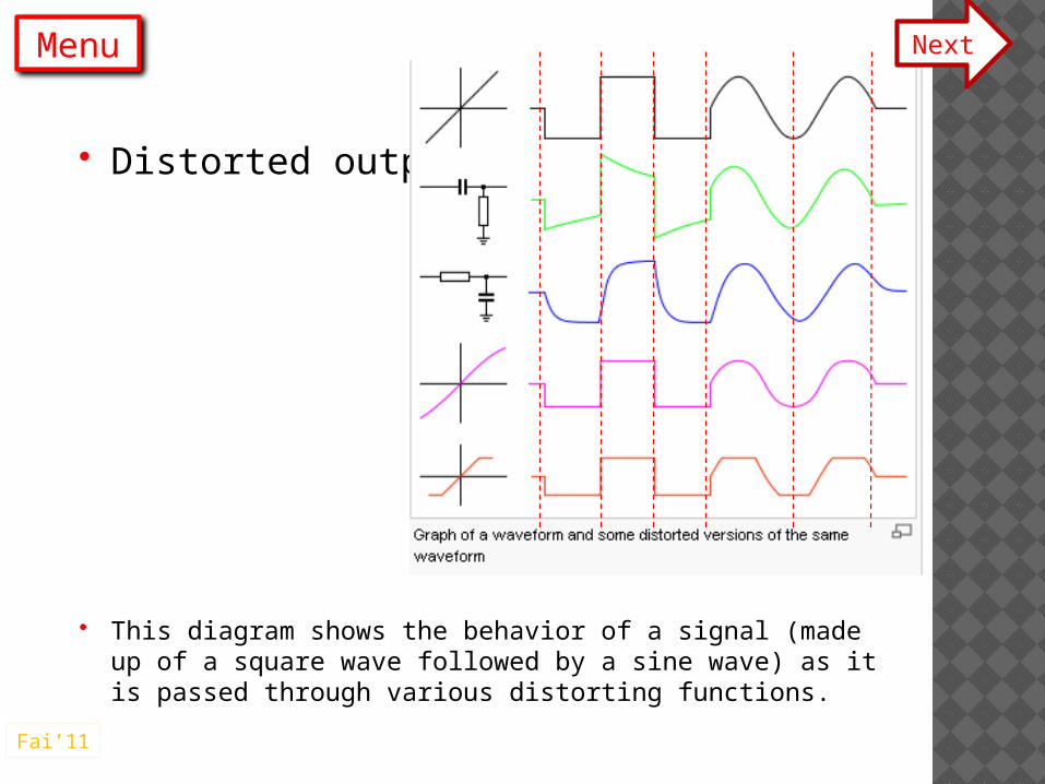
Distorted output
This diagram shows the behavior of a signal (made up of a square wave followed by a sine wave) as it is passed through various distorting functions.
NextMenu
Fai’11

Distorted output The first trace (in black) shows the
input. It also shows the output from a non-distorting transfer function (straight line).
A high-pass filter (green trace) will distort the shape of a square wave by reducing its low frequency components. As the sine wave contains only one frequency, its shape is unaltered.
A low-pass filter (blue trace) will round the pulses by removing the high frequency components.
NextMenu
Fai’11

A slightly non-linear transfer function (purple), this one is gently compressing as may be typical of a tube audio amplifier, will compress the peaks of the sine wave
A hard-clipping transfer function (red) will generate high order harmonics.
Parts of the transfer function are flat, which indicates that all information about the input signal has been lost in this region.
NextMenu
Fai’11

PRINCIPLE OF PA SYSTEM Stage in PA system
Preamplifier
Equalizer/tone control
Driver Power Amplifier
NextMenu
Fai’11

OBE Exercise.Discus in your group what is the purpose of
every stage below
Preamplifier
Equalizer/tone control
Driver
Power Amplifier.
NextMenu
Fai’11

TO BE CONTINUED IN NEXT CHAPTER,…
Menu
Fai’11