Embed Size (px)
Citation preview

“Studies on Radial Tipped Centrifugal Fan” 1
CHAPTER – 1 INTRODUCTION
1.1 Preamble
The world is facing serious challenges in energy. A global revolution is
needed in the ways that energy is produced, supplied and used. Total Energy
consumption by various sectors is shown in Figure 1.1. It shows that industries
consume almost 70% of total energy generated.
Figure 1.1 Energy Consumption by Various Sectors [1]
Manufacturing industries consumes about 85% of total industrial energy
usage. The non-manufacturing industries like agriculture, mining, oil and gas
extraction, and construction accounts for the remainder.
One of the biggest electricity consumers in the industrial sector is the motor
system, which is critical to both production process and facility end-users. For
example, material processing and handling, refrigeration, and compressed air, all use
motor drives to some extent. Figure 1.2, as given below shows the study of electricity
consumption of fan and pump systems in the industries, compared to other motor’s
applications.

Chapter – 1: Introduction
“Studies on Radial Tipped Centrifugal Fan” 2
Figure 1.2 Electricity Consumption of Motor [2]
Within the motor drive sub-set, pumps and fans are significant electricity
consumers and generally account for about 40% of motor system consumption.
Energy is also lost due to inefficiencies in the wide range of equipment used for pre-
process and manufacturing process activities using motors, mechanical drives, process
heaters and coolers and others. Compressors typically lose as much as 80 percent of
energy inputs, pumps and fans typically lose 35 to 45 percent, and motors lose 5 to 10
percent [1].
Electricity consumption by the installed industrial fans and blowers is
estimated at 45–55 terawatt-hours (TWh) per year. Centrifugal fans dominate among
total fan and blower market by consuming 90% of sector energy. Initial field research
suggests that substantial further reductions in industrial fan and blower electricity
consumption are possible at equipment, speed control and system design level as
quantified in Table 1.1.
Table 1.1 Energy Savings Potential for Specific Fan and Blower Systems [2] Equipment 5–15%
Speed Control* 20–50%*
System Design* 5–25%
* Applies to variable flow systems and includes ASDs as well as staging multiple fans to serve a load
response to varying air needs.
All industrial fans can be classified primarily as centrifugal and axial flow
fans. These types are characterized by the path of the airflow through the fan.
Centrifugal fans use a rotating impeller to increase the velocity of an airstream. As the
air moves from the impeller hub to the blade tips, it gains kinetic energy. This kinetic
energy is then converted to a static pressure increase as the air slows before entering
the discharge. Centrifugal fans are capable of generating relatively high pressures.

Chapter – 1: Introduction
“Studies on Radial Tipped Centrifugal Fan” 3
They are frequently used in “dirty” airstreams (high moisture and particulate content),
in material handling applications, and in systems at higher temperatures.
Centrifugal fans have the largest market share at 34%, while axial-flow fans
account for about a 23% of the market, and mixed flow and propeller fans have a
combined market share of about 43% as shown in Figure 1.3. In terms of fan
applications, general application is the largest at about 46% [3].
Figure 1.3 Market Shares of Centrifugal, Axial and Other Fans [3] Figure 1.4 and Table 1.2 shows sales market forecast of number of axial,
centrifugal, cross and box type of fans from the year 1995 to 2020 presenting their
growth trend. It utilizes advanced econometric techniques for short-term and long-
term growth trends. The sales value of the 2005 fan sales was around 5.5 billion euro
(industry turnover).
Figure 1.4 Unit Sales (Million) by Fan Type during 1995-2020 [4]

Chapter – 1: Introduction
“Studies on Radial Tipped Centrifugal Fan” 4
Table 1.2 Fan Sales by Their Types [4]
Fan Type Sales [number of millions]
1995 2000 2005 2010 2015 2020 2025
Axial < 300 Pa 0.90 2.25 2.40 2.62 3.00 3.39 3.78
Axial > 300 Pa 0.93 2.51 2.70 2.86 3.01 3.17 3.33
Centr. FC 0.46 0.66 1.12 1.04 1.20 1.36 1.52
Centr. BC-Free 0.14 0.21 0.33 0.31 0.35 0.39 0.43
Centr. BC 0.14 0.23 0.37 0.34 0.39 0.44 0.49
Cross Flow 0.13 0.23 0.19 0.26 0.30 0.34 0.37
Box 1.53 2.58 2.30 2.91 3.13 3.35 3.57
Roof all 1.99 3.87 3.40 4.10 4.33 4.55 4.78
Total 6.23 12.54 12.81 14.44 15.72 16.99 18.27
100% 113% 123% 133% 143%
This impact assessment identified a stock of 143 million units in 2005, rising
to 227 million in 2020. Figure 1.5 shows the relative stock increase of fan sales
against the 2005 situation.
Figure 1.5 Fan Stocks 1990 – 2025 [4]

Chapter – 1: Introduction
“Studies on Radial Tipped Centrifugal Fan” 5
1.2 Need of Energy Efficient Fan
Further advancement and research study and government measures in the field
of energy efficient fans are carried out all around the globe. On 27 May 2008, the
meeting of the Eco-design Consultation Forum took place and presented a working
document (CSWD) on eco-design requirements related to fans. The technical scope of
axial, centrifugal, cross-flow, box and roof fans is in the power range of
125 W – 500 kW was selected due to their major market share. Improvements in the
energy efficiency of fans should be achieved by applying existing nonproprietary
cost-effective technologies that can reduce the total combined costs of purchasing and
operating them [4].
The eco-design consultation forum considered and proposed the following
minimum efficiency levels by fan type and year of implementation (all referring to
static efficiency) as shown in Table 1.3.
Table 1.3 Average Efficiency and CSWD Minimum Efficiency Requirements (at Base Case Power) [4]
Fan category kW Avg.
Efficiency2010 2011 2012 2020
Axial, ≤ 300 Pa 0.8 30.9% 26.4 26.4 26.4 30.4
Axial, > 300 Pa 1.32 37.1% 30.4 30.4 30.4 34.4
Centrifugal / FC 0.44 32.1% 26.4 26.4 26.4 30.4
Centrifugal / plug 3.76 56.4% 53.4 53.4 53.4 57.4
Centrifugal / BC-AF 3.82 53. 7% 50.6 50.6 50.6 55.6
Cross flow fans 0.42 7.3% 8.0 26.3 26.3 30.3
Box fans 0.37 23.1% 18.2 18.2 18.2 22.2
Roof fans 1.2 43.6% 37.7 37.7 38.1 42.1
The minimum efficiency requirements are based on the function performed by
a fan. The proposed minimum energy performance requirements and the timing for
their introduction of first phase start from the year 2010. Now it is a time to redesign
and manufacture more efficient fans.
Energy-efficiency improvement options specifically on use of fans in cement,
refineries, fertilizers, chlor-alkali and textile industries of India are identified [5]. The
Indian textile industry contributes about 14% to the national industrial output and

Chapter – 1: Introduction
“Studies on Radial Tipped Centrifugal Fan” 6
about 25% to the total national export earnings. Their feasibility report has suggested
that technological up gradation of installed fan or their replacement with use of
improved efficiency fan with variable drive can save maximum energy. Improved
energy efficiency is an important component to increasing national energy security,
reducing the cost of energy, and combating climate change and environmental
degradation.
Above assessment indicates the need of improving design to achieve energy
efficient centrifugal fan used in textile industry. Hence this research work is based on
an industrial requirement of re-designing fume extraction centrifugal fan used in SDS-
9 texturising machine of medium scale textile industry.
1.3 Turbomachines
The word turbo or turbine is of Latin origin and implies that which spins or
whirls around. Turbo-machines are defined as “A device in which energy is
transferred to or from a continuously moving fluid by the dynamic action of a moving
blade row. The blade row rotates and changes the stagnation pressure of the fluid by
either doing work on the fluid (as a fan/ pump) or by having work done on the blade
row by the fluid (as a turbine)” [6,7].
According to the Compressed Air Institute, fans are used where low pressures
(from few mm of water to nearly 7-kPa gauge pressure) and comparatively large
volumes are required to handle. They run at relatively low speeds, the casing and
impeller are usually built from iron sheets. Blowers are defined where a final pressure
is not exceeding 240 kPa. Blower is having higher flow resistance on delivery side
while fan is having such resistance on suction side. Similarly, a centrifugal
compressor is used to compress air or gas to a final pressure above 240 kPa.
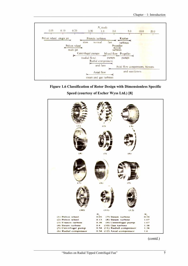
Turbo machines are classified based on principal flow directions such as axial
flow machines, radial flow machines and mixed flow machines. They are also
classified based on specific speed. Sayers [8] have given a much generalized
classification of these machines as shown in Figure 1.6 while Figure 1.7 gives specific
rotor designs with their dimensionless specific speeds.
F
“Stud
Figure 1.6 C
S
dies on Radial
Classificati
Speed (cour
l Tipped Cent
ion of Roto
rtesy of Esc
trifugal Fan”
r Design w
cher Wyss
Ch
with Dimens
Ltd.) [8]
hapter – 1: Int
sionless Spe
(con
troduction
7
ecific
ntd.)

“Stud
Figure 1.7
dies on Radial
7 Rotor De
l Tipped Cent
signs and T
trifugal Fan”
Their Dime [8]
Ch
ensionless S
hapter – 1: Int
Specific Spe
troduction
8
eed

Chapter – 1: Introduction
“Studies on Radial Tipped Centrifugal Fan” 9
The centrifugal machines are further classified based on blade geometry which
governs the loss and their performance, too.
Forward curved blade tips are inclined towards the direction of rotation and
exit blade angle β2 is greater than 90°. This results in large blade angles and higher
flow rate and higher stage pressure rise. Exit whirl component Vu2 is large and is
leading to a higher stage pressure rise. This type of blade is normally used for low
pressure heating, ventilating and air conditioning of domestic furnaces and packaged
air conditioning equipment.
Radial blade has tip (or even the whole blade in the case of paddle bladed
fans) in radial direction at exit having exit blade angle β2 is equal to 90°. Radial blade
with curved surface is known as radial tipped blade. This type of blades is generally
used in material handling applications having dirty or erosive environment.
Backward curved blade tip has its inclination away from the direction of
rotation which causes exit blade angle β2 less than 90°. The blade passage expands
gradually so airflow will decelerate gradually and will have minimum turbulence.
Hydraulic performance of centrifugal fan is governed by inlet and exit velocity
triangle. Velocity triangles for a turbo machine contain peripheral velocity (U) of
rotor blades, the absolute velocity (V) and relative velocity vector (W). These velocity
vectors and blade and flow angles are shown in Figure 1.8 at impeller entry and exit
with tangential direction taken as reference direction, for each case of forward, radial,
and backward curved impeller.

Chapter – 1: Introduction
“Studies on Radial Tipped Centrifugal Fan” 10
Figure 1.8 Velocity Triangles for Different Blade Profiles [9]
1.4 Fan Selection and Performance Characteristic Curves
[10, 11, 12]
In manufacturing, fan reliability is critical for plant operation. The importance
of fan reliability often causes system designers to design fan systems conservatively
by over sizing.
The choice of fan type for a given application depends on the required
magnitudes of flow, static pressure and rotational speed. High speed units are
generally more economical because of their higher hydraulic efficiency and relatively
low cost and smaller in size. However, for low pressure ratios, large sized low-speed

Chapter – 1: Introduction
“Studies on Radial Tipped Centrifugal Fan” 11
units are preferable. The use of a “systems approach” in the fan selection process will
typically yield a quieter, more efficient, and more reliable system.
The operating costs of large fans are often high enough and hence improving
fan system efficiency can offer a quick payback.
Fan characteristics can be represented in form of fan curves. The fan curve is a
performance curve for the particular fan under a specific set of conditions. It is a
graphical representation of a number of inter-related parameters like fan volume,
system static pressure, fan speed and shaft power/BHP required to drive the fan under
the stated conditions. An important aspect of a fan performance curve is the best
efficiency point (BEP). At BEP a fan operates most cost-effectively in terms of both
energy efficiency and maintenance considerations. Operating a fan near its BEP
improves its performance and reduces wear.
The intersection of the system resistance curve and the static pressure curve
defines the operating point. A horizontal line drawn through the intersection with the
power curve will lead to the required power on the right vertical axis. Figure 1.9
shows graphical representation of manufacturer’s test data for a typical fan. In this
Figure, the fan efficiency curve is also presented. It is important to note that a fan
operates along a performance given by the manufacturer only for a particular fan
speed.
Figure 1.9 Manufacturer’s Fan Characteristic/Performance Curves [12]

Chapter – 1: Introduction
“Studies on Radial Tipped Centrifugal Fan” 12
Typical static pressure and shaft power with respect to volume flow for
forward, backward and radial blade type fans are given in the Figure 1.10.
Figure 1.10 Static Pressure, Shaft Power V/s Volume Flow Curves for Different
Types of Blades [12]
Figure 1.11 shows effect of impeller rotational speed on head developed, shaft
power required, total efficiency and discharge. These curves are plotted as a set of
constant speed lines.
Figure 1.11 Centrifugal Fan Characteristic Curves [10]

Chapter – 1: Introduction
“Studies on Radial Tipped Centrifugal Fan” 13
Non dimensional performance parameters like power coefficient
λ P/ρ N3D5), and pressure coefficient (ψ gH/ N2D2), flow coefficient
(φ Q / ND3) as well as efficiency (η) are used to analyze standard fan performance.
These curves, based upon non - dimensional parameters can be plotted for a family of
geometrically similar fans operating under dynamically similar conditions. These non
dimensional performance curves are shown in Figure 1.12.
Figure 1.12 Centrifugal Fans Non-Dimensional Performance Curves [10]
1.5 Cordier Diagrams
[7, 13]
In the early of 1950s, Cordier had carried out an intensive empirical analysis
of “good” turbo-machines by using extensive experimental data. He had converted
these performance parameters into dimensionless correlations. He has used
dimensionless specific speed Ns and diameter coefficient δ (or Ds) as their
performance yardsticks.
He has made graphical presentation of these correlations and categorized all
axial, centrifugal and mixed flow turbo machines on the basis of these correlations. A
trend line of best efficiency performance of various turbo machines is prepared in the
form of curve. He found that subject to uncertainty and scatter in data, those
turbomachines which have excellent efficiencies, adhere close to the mean curve. So
it represents a fairly broad spread of results on either side of line. These curves are
very well known as Cordier diagrams and they are very useful tool for any designer to
specify that which class and type of turbo machine will serve their requirement

Chapter – 1: Introduction
“Studies on Radial Tipped Centrifugal Fan” 14
efficiently. These curves will not give exact solution but will lead to approximate
solution so that design process can start in right direction. Performance of actual fans
which is falling away to Cordier line is defined as moderate or less efficiency fans.
Specific speed is a criterion at which a fan of unspecified diameter would run
to give unit volume flow and pressure. This applies to all fans in a homologous series.
This is derived from the fan laws by elimination the diameter term, thus:
Discharge Q based specific speed is used for pumps, compressors, fans and blowers.
/
Power P, based specific speed is used for all types of turbines.
Cordier diagrams relating specific speed versus diameter coefficient and speed
coefficient versus diameter coefficient with total efficiency selection are shown in
Figures 1.13 and 1.14, respectively.
Figure 1.13 Cordier Diagrams Correlating Specific Speed Ns and Diameter
Coefficient δ For Pump and Fan Selection [13]

Figure 1
Lew
in terms of
Figure 1.15
Figure
“Stud
1.14 Cordie
Coe
wis [15] ma
f pressure or
5.
e 1.15 Lewis
dies on Radial
er's Diagra
efficient δ f
ade a useful
r head coeff
s Cordier d
l Tipped Cent
m Correlat
for Pump a
l and alterna
fficient ψ an
diagram for
coefficient
trifugal Fan”
ting Speed
and Fan Sel
ative presen
nd volume f
r head coef
t Φ [13]
Ch
Coefficien
lection [14]
ntation of th
flow coeffic
fficient ψ V
hapter – 1: Int
t σ Vs Diam
]
he Cordier
cient Φ as s
Vs volume f
troduction
15
meter
diagram
hown in
flow

Chapter – 1: Introduction
“Studies on Radial Tipped Centrifugal Fan” 16
1.6 Laboratory Methods for Performance Testing of Fans and Blowers - An Overview of Test Codes
[16, 17, 18, 19] Theoretical estimation of fan performance and associated slip and other losses
cannot be done accurately. Proven design must be validated by accurate test results.
The performance of any fan can be affected by many variables at suction and
discharge. Real performance characteristics of a fan or blower can only be truly
ascertained by accurate tests.
Field tests are considered less reliable than laboratory tests, because at field,
the flow conditions may not be identical as prescribed in test standards. If the
laboratory tests are conducted strictly in accordance with the relevant standard, the
performance data will accurately reflect fan performance within the appropriate
tolerances for efficiency, pressure and flow when tested in the defined configuration.
Fan test standards have been prepared in order to establish a clearly defined test
procedure that allows for comparison of different fan designs, and also allows for the
independent verification of test data.
Internationally recognized standards are AMCA210, BS848, IS4894 and
ISO5801. These are highly prescriptive, and precisely specify test duct configurations,
measurement procedures, measurement planes and instrumentation to be used.
• AMCA 210 Standard for fan testing
This standard provides rules for testing fans under laboratory conditions to
provide rating information. It was prepared by a joint committee consisting of the Air
Movement and Control Association Inc review committee (AMCA 210) and the
American Society of Heating, Refrigerating and Air Conditioning Engineers, Inc
(ASHRAE) standard 51-75R committee. This joint committee unanimously decided
that AMCA standard 210-74 and ASHRAE standard 51-75 could be reaffirmed with
minor revisions and published as ANSI/AMCA STANDARD 210-85
ANSI/ASHRAE STANDARD 51-1985 titled as “American National Standard
Laboratory Methods of Testing Fans for Rating”. This standard includes
description of units of measurement, definitions, instruments and methods of
measurement, equipment and test setups, calibration corrections, observations and
conduct of test, testing by various flow sections, similarity and fan laws and
uncertainty analysis.

Chapter – 1: Introduction
“Studies on Radial Tipped Centrifugal Fan” 17
Fig. 1.16 shows schematic inlet duct test setup arrangements as suggested by
this standard.
• Location 1 stands for fan inlet, 2 stands for fan outlet, 3 stands at pitot transverse station
• Psr= Fan static pressure reading, Pvr= Fan velocity pressure reading • D= Diameter and equivalent diameter, L= Length of duct • Td= Dry bulb temperature, PL= Plane
Figure 1.16 Schematic Inlet Duct Test Setup Configurations as per ANSI/AMCA 210-85 [16]
• BS 848 Standard for fan testing
This international standard is the result of almost thirty years of discussion,
comparative testing and detailed analyses by leading specialists from the fan industry
and research organizations throughout the world.ISO/TC 117 committee had started
its work in 1963 and published subsequent revisions of various national standards.
British Standard BS 848: Part 1: 1997 “Fans for General Purposes –
Part 1: 1997, Performance Testing Using Standardized Airways” is now
reaffirmed by a Technical Committee ISO/TC 117, Industrial fans, Subcommittee
SC 1, Fan performance testing using standardized airways, as ISO 5801 “ Industrial
Fans – Performance Testing Using Standardized Airways” (First Edition 1997-06-01).
This standard includes A to D types of standardized installation to be tested where
type A is free inlet and outlet, type B is free inlet and ducted outlet, type C is ducted
inlet and free outlet and type D is for ducted inlet and outlet. Fan pressure is defined
as total pressure difference across the fan and compressibility of air is taken care if

Chapter – 1: Introduction
“Studies on Radial Tipped Centrifugal Fan” 18
high accuracy is required. Simplified methods can be used if Mach number does not
exceed 0.15. It explains standard methods to calculate average pressure in airway
duct, measurement of temperature, speed, input power and flow-rate. It includes
uncertainty analysis in measurements with maximum allowable uncertainties in
measurements and calculated results. This standard employs SI units of measurement.
Fig. 1.17 shows schematic inlet duct test setup arrangements as suggested by
this standard.
• Pe= Gauge pressure reading at pressure measurement section • D3= Internal diameter of a circular conduit at pressure measurement section • P= Differential pressure
Figure 1.17 Schematic Inlet Duct Test Setup Configurations as Per BS 848:
Part 1: 1997 [18]
• IS : 4894-1987 Standard for fan testing
The Indian Standard IS: 4894-1987 reaffirmed in 1994 is titled as “Indian
Standard - Specification for Centrifugal Fans” (First Revision) is published by
Bureau of Indian Standards (BIS), New Delhi for the testing of centrifugal fans. The
centrifugal fans covered by this standard are capable of working against pressure. In
preparing this standard, some assistance has been drawn from BS 848: Part 1:1980,
"Fans for General Purposes: Part 1 Methods for Testing Performance”. It (IS: 4894-
1987) describes terminology, performance rating, and point of rating, type of routine
and acceptance tests and sizes covered. It also includes general and electrical safety
requirements. Air delivery tests includes norms for airway inlet duct, manometers and
square blocks, values of coefficient of discharge for conical inlet with respect to
Reynolds number, use of resistance screens and locations for pressure tapping are
unique features of this standard. This standard facilitates formulae for computing and

presentation
arrangemen
*D
dia
Figure 1
All
and reporti
measureme
The setups
straight uni
necessary t
advised wh
1.7 Com
Com
techniques
successfully
cars and
thermodyna
stationary
releases en
by solving
dynamics a
“Stud
n of results
nts as sugge
D stands for
ameter by no
1.18 Schem
three test c
ing tests of
ents, and cal
differ princ
iform flow.
o ensure ac
hen exceptio
mputationa
mputational
together
y applied in
aircraft, h
amics of fa
and rotatin
ergy. There
g mass, mo
analysis redu
dies on Radial
s and efficie
ested by this
r straight air
ot more tha
atic Inlet D
codes narra
f the air m
lculations a
cipally with
However,
ccuracy of m
ons are cont
al Fluid Dy
l Fluid Dyn
to solve
n many area
hydrodynam
an, blower,
ng parts. Fl
e are many
omentum an
uces substa
l Tipped Cent
ency. Fig. 1
s standard.
rway duct d
an 20% large
Duct Test S
1994 [
ated above p
moving fans
amongst stan
h regard to l
since most
measuremen
templated.
ynamics (CF
namics (CFD
problems
as of fluid m
mics of s
compressor
luid passing
methods to
nd energy
antial time a
trifugal Fan”
.18 shows
diameter, it
er or 5% sm
etup as per
[17]
provide stan
s. There are
ndards, but
location and
t of the prov
nt and repro
FD)
D) is the us
involving
mechanics. T
ships, pum
r etc. Turbo
g through
o identify ro
transfer eq
and cost in d
Ch
schematic i
t may differ
maller.
r IS: 4894-1
ndard meth
e some dif
results rem
d type of de
visions of t
oducibility o
se of compu
fluid flow
This includ
mps and t
omachines
these passa
otating parts
quations. C
developing
hapter – 1: Int
inlet duct te
r from the f
1987 reaffi
hods for con
fferences in
main generall
evice used t
these test co
of results, ca
uters and nu
w. CFD ha
des aerodyna
turbines e
are combin
ages either
s and its sim
Computation
new design
troduction
19
est setup
fan inlet
rmed:
nducting
n setups,
ly same.
to insure
odes are
aution is
umerical
as been
amics of
tc. and
nation of
gets or
mulation
nal fluid
ns. It has

Chapter – 1: Introduction
“Studies on Radial Tipped Centrifugal Fan” 20
ability to study system variables and its effect without conducting experiments or
where it is very difficult to perform experiments. CFD gives feasible solution of the
problem which is under hazardous conditions in real. It also extends its solution
beyond the workable boundaries of the problem. It allows checking solution optimally
by offering wide range of variable parameters for a problem under study.
From the mid-1970's, the complex mathematics was generalized by the
algorithms developed. Afterwards in the early 1980's algorithms were well developed
and need of powerful computer processors was emerged. Recent advances in
computing power, together with powerful graphics and interactive 3D manipulation of
models, have made the process of creating a CFD model and analyzing results offer
better flow visualization at reduced time and cost.
3-D CFD analysis of various flow phenomenons occurring inside
turbomachine can be numerically analyzed with the help of commercially available
CFD softwares. The set of equations which describe the processes of momentum, heat
and mass transfer are known as the Navier-Stokes equations. These partial differential
equations were derived in the early nineteenth century and had no analytical solution
but it can be only discretized and solved numerically. In recent time, there are three
different types of numerical solution techniques available to solve governing
equations by computational fluid dynamics known as FDM, FEM and FVM. They
differ from each other due to difference in approximation of flow variables and
discretization method. Finite difference method (FDM) solves the governing
equations at node points of generated grids. This method is simple but it has more
approximation compare to other two methods. Finite element method (FEM) uses
elements of generated grid for describing local variations of unknown flow variables.
The governing equations are precisely satisfied by the exact solution by this method.
Finite volume method (FVM) integrates governing equations of fluid flow all over the
control volume. It converts integral equations into a system of algebraic equations.
These algebraic equations can be solved by iterative methods.
Centrifugal fan design performance can be truly ascertained by experimental
evaluations, but CFD analysis can greatly help in reducing number of experimental
iterations. CFD can also help to understand profile distribution of mass flow, pressure
and velocity at infinitesimal planes of centrifugal fan geometry under study. This
could not be possible merely by experiments and hence CFD analysis and
experimental evaluation are equally important and mutually exclusive.

Chapter – 1: Introduction
“Studies on Radial Tipped Centrifugal Fan” 21
1.8 Scope of Present Work
Fans are widely used in industrial and commercial applications. Centrifugal
fans have the largest market share as 34% amongst all other type of fans. Centrifugal
fans dominate among total fan and blower market by consuming 90% of sector
energy. Accordingly, the focus of present work is towards evolution of energy
efficient fans used in textile industries. It aims at redesigning fume extraction
centrifugal fan used in SDS-9 texturising machine of medium scale textile industry.
This application demands fume extraction at constant head. Radial vaned
centrifugal fans being ideal choice for such application [9, 20, 21, 22], the work is
focused towards evolution of energy efficient radial tipped centrifugal fan. The
process of energy efficient design requires understanding of influence and
optimization of number of blades, assessment of existing design methodologies,
evaluation of slip factor and losses and there after proposing design process which is
there after validated through experiments and 3-D CFD studies. This in general
demands extensive studies on centrifugal fan.
These aspects defines the scope of work in the direction of compilation and
experimental evaluation of existing design methodologies for radial tipped centrifugal
fan, optimization of finite number of blades through experimental studies at design
and off design conditions, determination of experimental values of slip factor at
different volute locations and along blade width to verify empirical correlations of slip
factor, experimental evaluation of hydraulic, leakage and power losses to ascertain
designed fan performance and finally offer a unified design methodology thoroughly
validated by experiments and numerical approach by 3-D CFD analysis which
ultimately meets or surpasses the CSWD minimum efficiency requirements for
centrifugal fans [4].