Embed Size (px)
Citation preview
7/29/2019 Chapter 06 Intro to Logic
http://slidepdf.com/reader/full/chapter-06-intro-to-logic 1/37
Chapter 6
Introduction to Logic
7/29/2019 Chapter 06 Intro to Logic
http://slidepdf.com/reader/full/chapter-06-intro-to-logic 2/37
Objectives
• Explain AND logic.
• Describe OR logic.
• Explain NOT logic.
• Explore a truth table for specified logic.
• Determine if a PLC ladder rung is true or
false under specified conditions.
7/29/2019 Chapter 06 Intro to Logic
http://slidepdf.com/reader/full/chapter-06-intro-to-logic 3/37
Hardwired Electrical Circuit Has
Electrical Continuity
• Hardwired circuit has actual current flow.
• This is called electrical continuity.• Current flows through switching device to
directly control the load.
7/29/2019 Chapter 06 Intro to Logic
http://slidepdf.com/reader/full/chapter-06-intro-to-logic 4/37
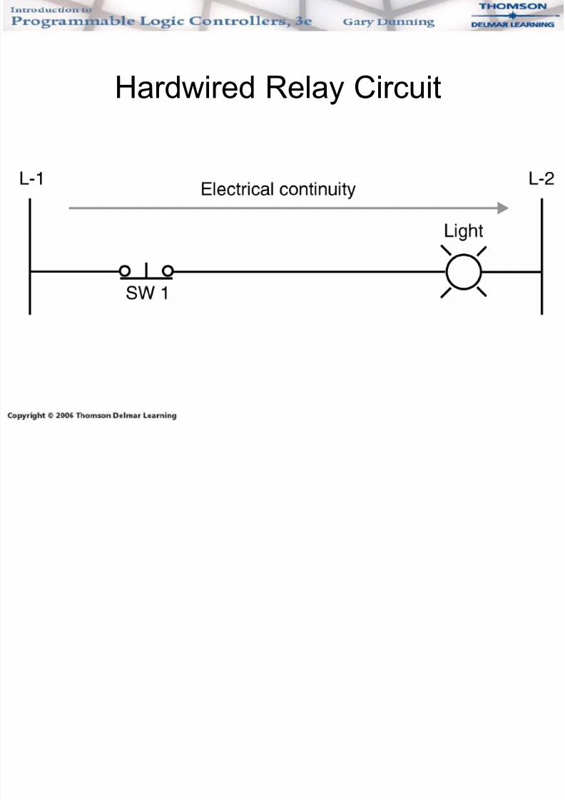
Hardwired Relay Circuit
7/29/2019 Chapter 06 Intro to Logic
http://slidepdf.com/reader/full/chapter-06-intro-to-logic 5/37
Logical Continuity (1 of 3)
• Hardwire relay circuits have electrical
continuity or current flow.
• PLCs do not operate on electrical continuity,but logical continuity.
7/29/2019 Chapter 06 Intro to Logic
http://slidepdf.com/reader/full/chapter-06-intro-to-logic 6/37
Logical Continuity (2 of 3)
• A PLC ladder program resembles an electric
schematic.
• A PLC program is a set of instructions storedin memory.
• PLC ladder symbols represent ladder
program instructions.
7/29/2019 Chapter 06 Intro to Logic
http://slidepdf.com/reader/full/chapter-06-intro-to-logic 7/37
Logical Continuity (3 of 3)
• PLC instructions examine the status of a bit
at the associated address.
• Bits are either a 1 or 0.
• Instructions are either true or false.
• PLCs have logical continuity.
7/29/2019 Chapter 06 Intro to Logic
http://slidepdf.com/reader/full/chapter-06-intro-to-logic 8/37
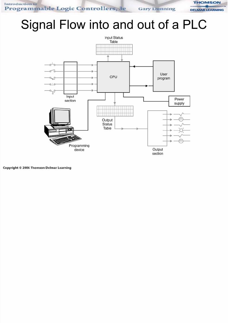
Signal Flow into and out of a PLC
7/29/2019 Chapter 06 Intro to Logic
http://slidepdf.com/reader/full/chapter-06-intro-to-logic 9/37
Input Signal Seen by Input Module
• Signal from field device is wired to input
module screw terminals.
• These signals are called input signals or simply inputs.
• Each input point has a unique identifier called
an address.
7/29/2019 Chapter 06 Intro to Logic
http://slidepdf.com/reader/full/chapter-06-intro-to-logic 10/37
Input Module Isolates and Converts
• Discrete input module determines if input is a
valid ON signal.
• The discrete input module converts theincoming electrical signal to +5V DC, or 0V
DC.
• An ON state will be converted to +5V DC.• An OFF state will be converted to 0V DC.
7/29/2019 Chapter 06 Intro to Logic
http://slidepdf.com/reader/full/chapter-06-intro-to-logic 11/37
Input Section to Back Plane
• The high voltage input signal is isolated from
the lower voltage microprocessor and
supporting circuitry in the processor.• Signal is then transferred to the chassis back
plane and sent to processor memory for
storage.
7/29/2019 Chapter 06 Intro to Logic
http://slidepdf.com/reader/full/chapter-06-intro-to-logic 12/37
Processor and Input Status File
• Field input signals are transferred from the
input module by way of the back plane for
storage in the processor’s input status file. • There is one storage location in the status
table for the ON or OFF status of each input
device.• The ON signal is stored as a 1; the OFF as a
0.
7/29/2019 Chapter 06 Intro to Logic
http://slidepdf.com/reader/full/chapter-06-intro-to-logic 13/37
Processor Examines
Status Table Bit• When running, the processor solves ladder
instructions by examining the ON or OFF
status of the input device by examining theassociated memory location for a 1 or 0.
7/29/2019 Chapter 06 Intro to Logic
http://slidepdf.com/reader/full/chapter-06-intro-to-logic 14/37
Ladder Program Solved
• Ladder instructions have rules regarding
when they are true or false.
– Instructions are made true or false as a resultof the examined bit.
– If there is a path of true input instructions to
the output instruction, the rung will be true.
7/29/2019 Chapter 06 Intro to Logic
http://slidepdf.com/reader/full/chapter-06-intro-to-logic 15/37
Output Update
• When all ladder rungs have been solved, the
output status table data is sent to the
respective output modules one word at atime.
• When a rung is solved, the output status
table is updated.
7/29/2019 Chapter 06 Intro to Logic
http://slidepdf.com/reader/full/chapter-06-intro-to-logic 16/37
Combining and Solving
Ladder Instructions• Three basic types of logic:
– And
– Or
– And / Or (combinational)
7/29/2019 Chapter 06 Intro to Logic
http://slidepdf.com/reader/full/chapter-06-intro-to-logic 17/37
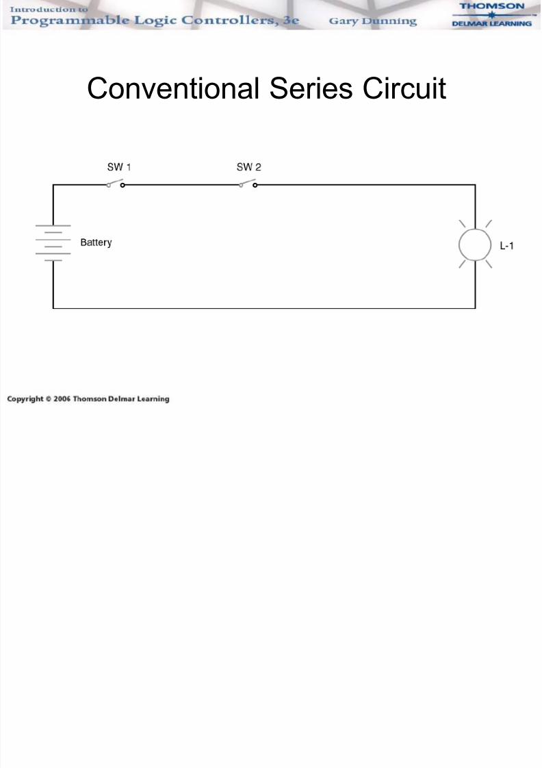
Series Logic
• When two switches are wired in series, both
switches must be on before power will flow.
• Switch 1 AND switch 2 must all pass power before light 1 will turn on.
7/29/2019 Chapter 06 Intro to Logic
http://slidepdf.com/reader/full/chapter-06-intro-to-logic 18/37
Conventional Series Circuit
7/29/2019 Chapter 06 Intro to Logic
http://slidepdf.com/reader/full/chapter-06-intro-to-logic 19/37
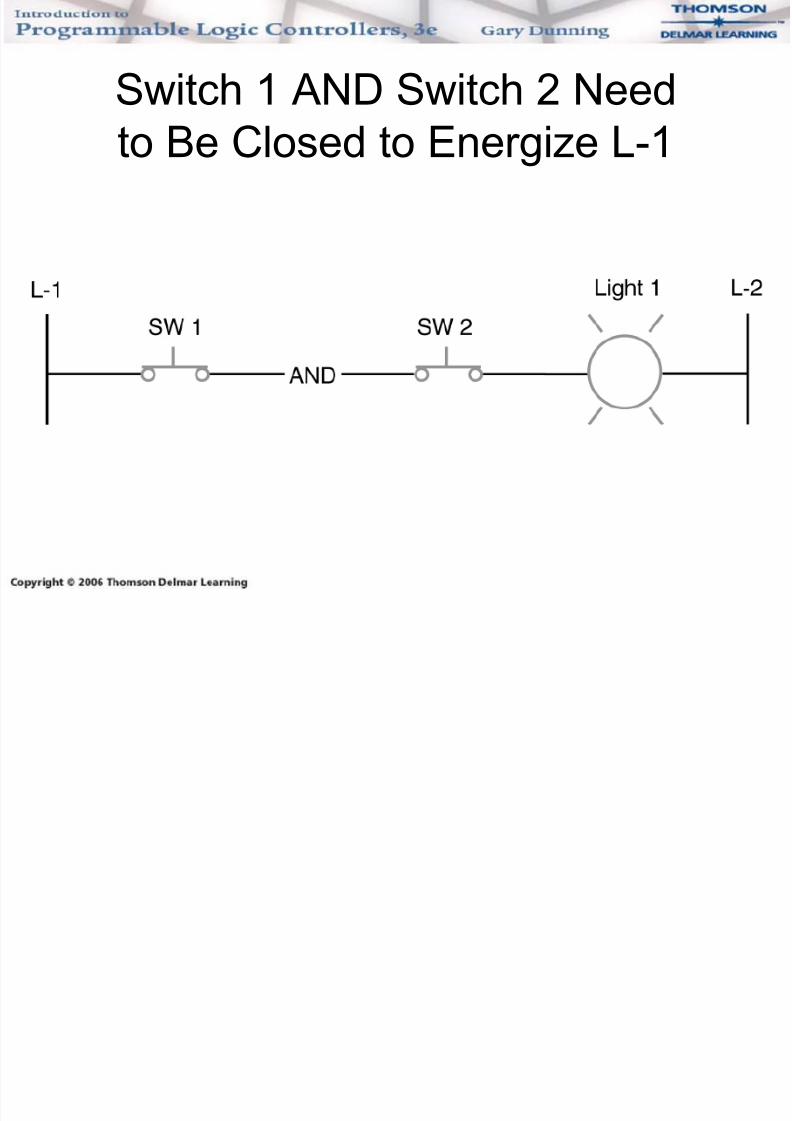
Switch 1 AND Switch 2 Need
to Be Closed to Energize L-1
7/29/2019 Chapter 06 Intro to Logic
http://slidepdf.com/reader/full/chapter-06-intro-to-logic 20/37
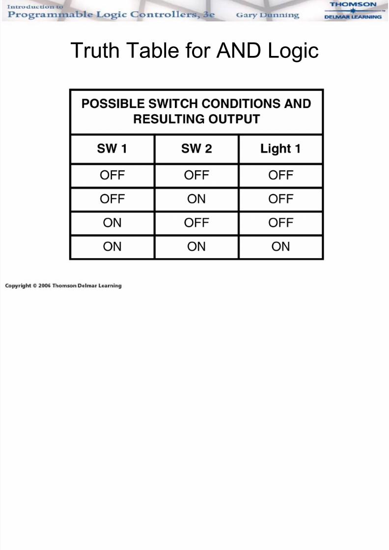
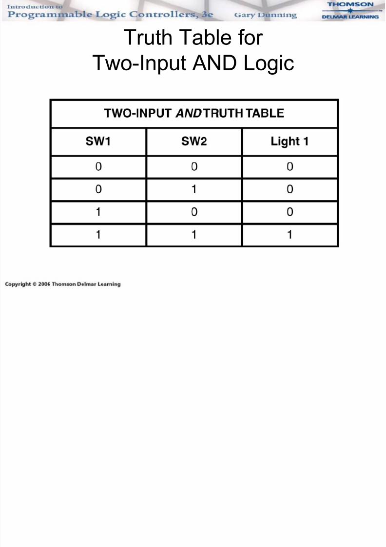
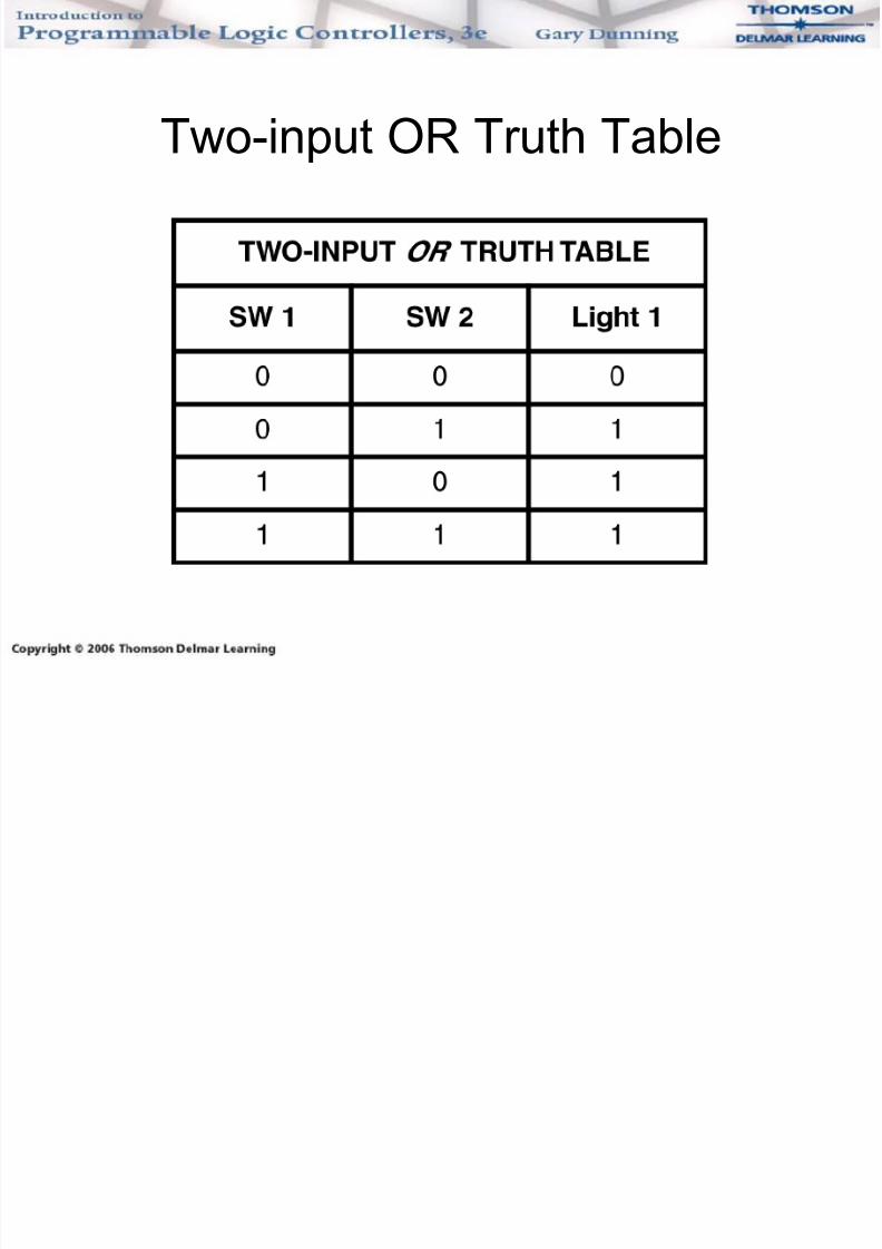
Truth Table
• A truth table shows all possible input
conditions and the expected output
conditions.• The following slide shows a truth table for
AND logic.
7/29/2019 Chapter 06 Intro to Logic
http://slidepdf.com/reader/full/chapter-06-intro-to-logic 21/37
Truth Table for AND Logic
7/29/2019 Chapter 06 Intro to Logic
http://slidepdf.com/reader/full/chapter-06-intro-to-logic 22/37
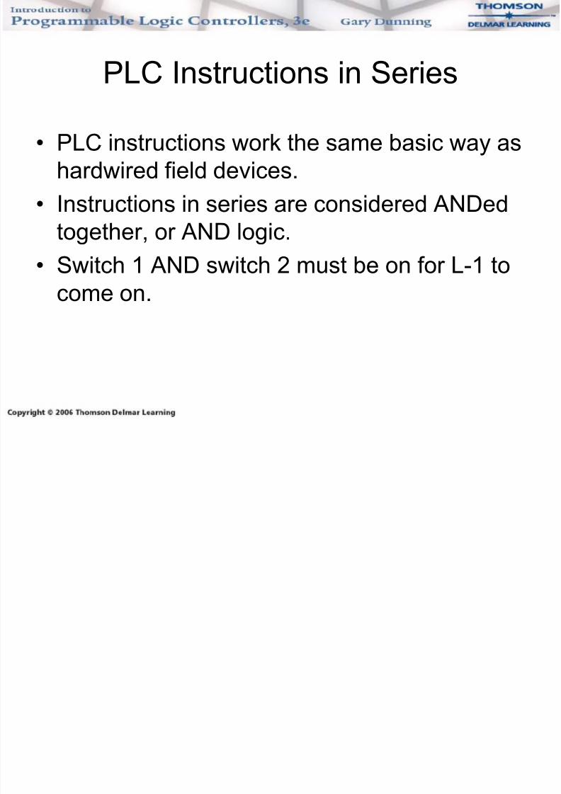
PLC Instructions in Series
• PLC instructions work the same basic way as
hardwired field devices.
• Instructions in series are considered ANDedtogether, or AND logic.
• Switch 1 AND switch 2 must be on for L-1 to
come on.
7/29/2019 Chapter 06 Intro to Logic
http://slidepdf.com/reader/full/chapter-06-intro-to-logic 23/37
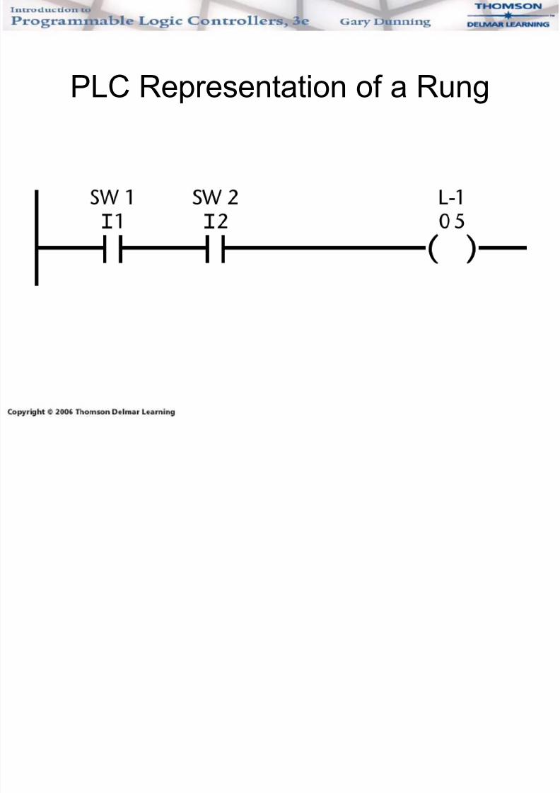
PLC Representation of a Rung
7/29/2019 Chapter 06 Intro to Logic
http://slidepdf.com/reader/full/chapter-06-intro-to-logic 24/37
Truth Table for
Two-Input AND Logic
7/29/2019 Chapter 06 Intro to Logic
http://slidepdf.com/reader/full/chapter-06-intro-to-logic 25/37
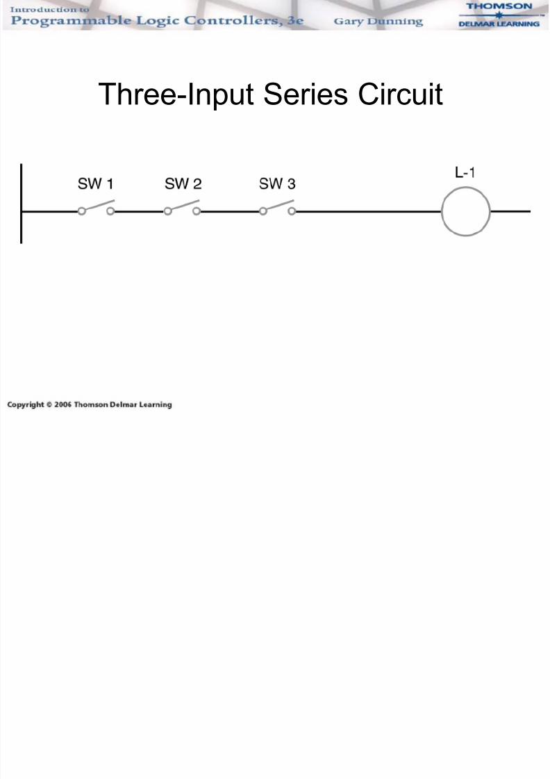
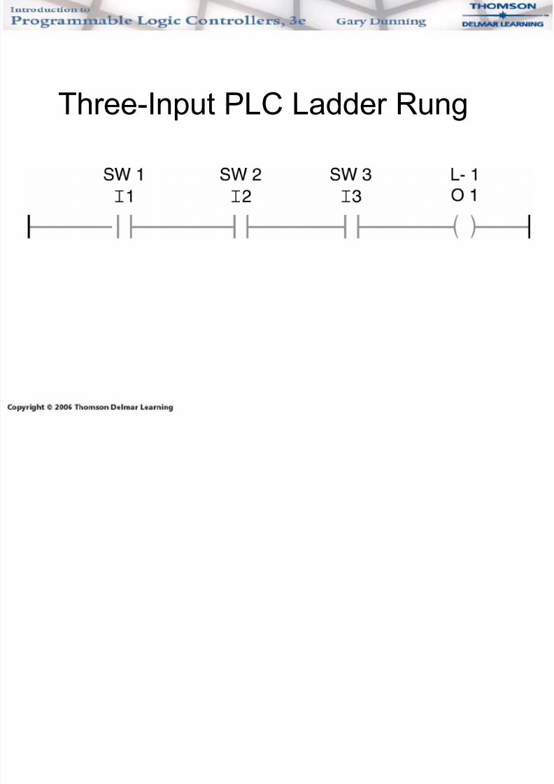
Three-Input Series Circuit
7/29/2019 Chapter 06 Intro to Logic
http://slidepdf.com/reader/full/chapter-06-intro-to-logic 26/37
Three-Input PLC Ladder Rung
7/29/2019 Chapter 06 Intro to Logic
http://slidepdf.com/reader/full/chapter-06-intro-to-logic 27/37
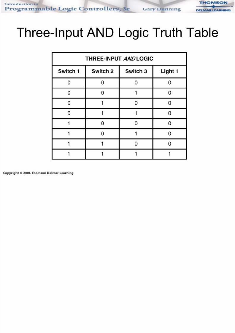
Three-Input AND Logic Truth Table
7/29/2019 Chapter 06 Intro to Logic
http://slidepdf.com/reader/full/chapter-06-intro-to-logic 28/37
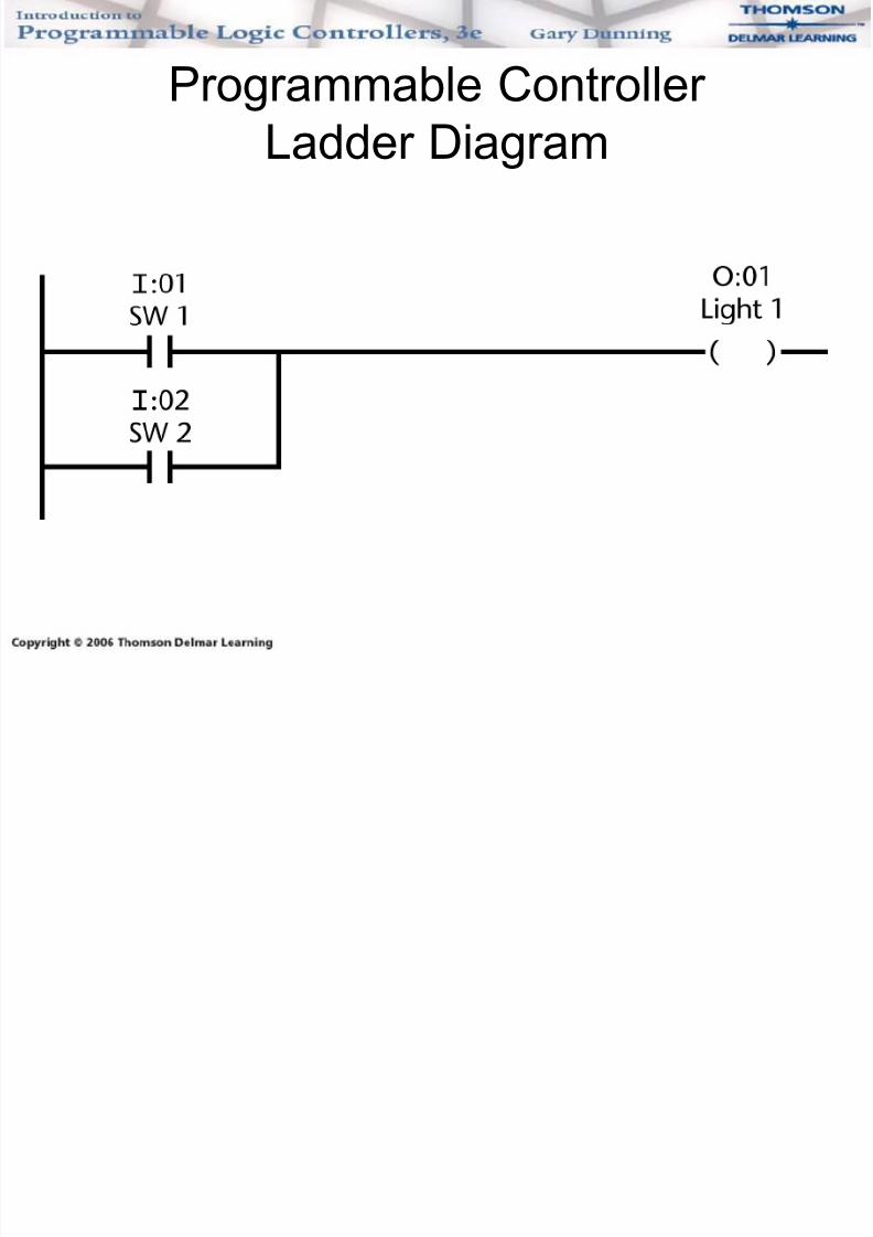
Parallel Is also OR Logic
• Inputs in parallel are said to be ORed.
• Switch 1 is ORed with switch 2.
• If switch 1 is closed OR switch 2 is closed,
light 1 will turn on.
• If both SW1 and SW2 are closed, light 1 will
turn on.
7/29/2019 Chapter 06 Intro to Logic
http://slidepdf.com/reader/full/chapter-06-intro-to-logic 29/37
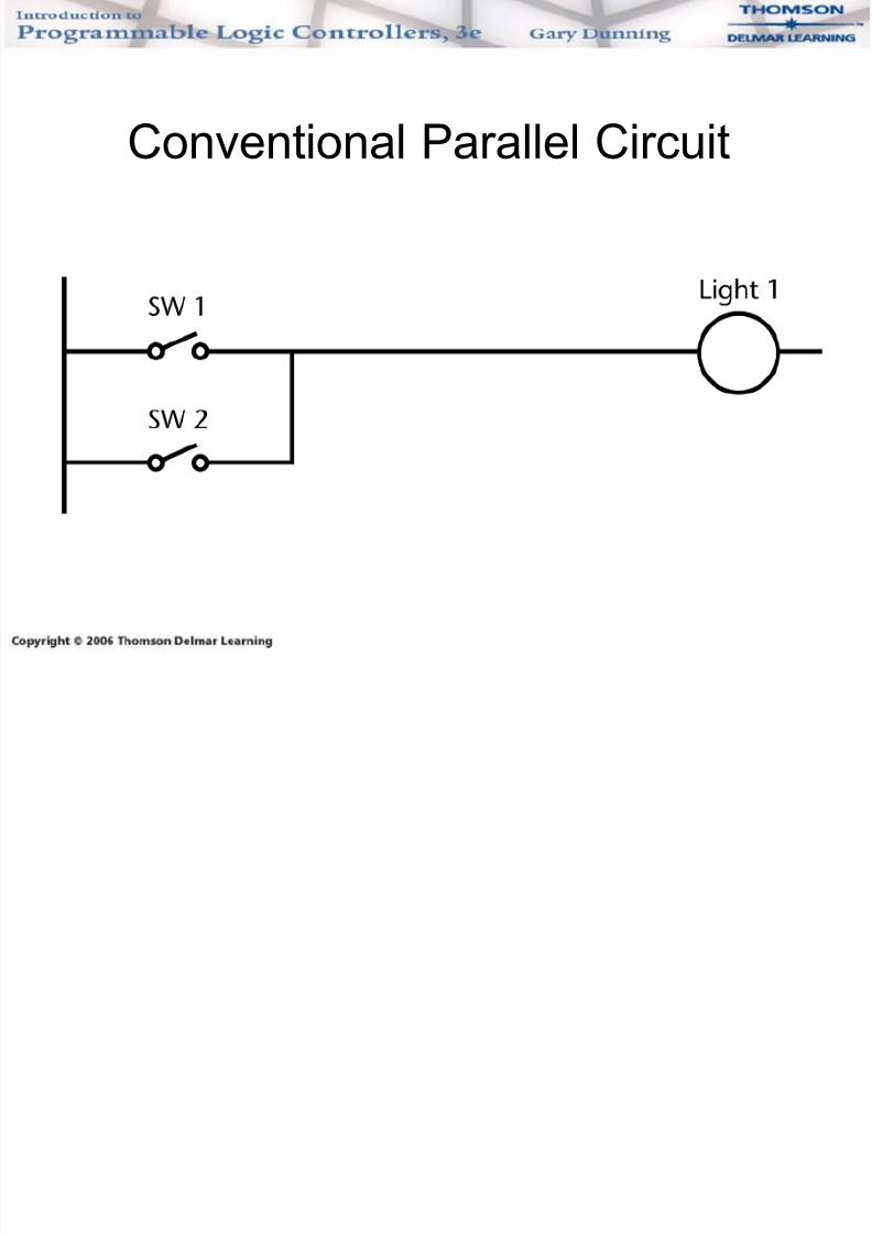
Conventional Parallel Circuit
7/29/2019 Chapter 06 Intro to Logic
http://slidepdf.com/reader/full/chapter-06-intro-to-logic 30/37
Programmable Controller
Ladder Diagram
7/29/2019 Chapter 06 Intro to Logic
http://slidepdf.com/reader/full/chapter-06-intro-to-logic 31/37
Two-input OR Truth Table
7/29/2019 Chapter 06 Intro to Logic
http://slidepdf.com/reader/full/chapter-06-intro-to-logic 32/37
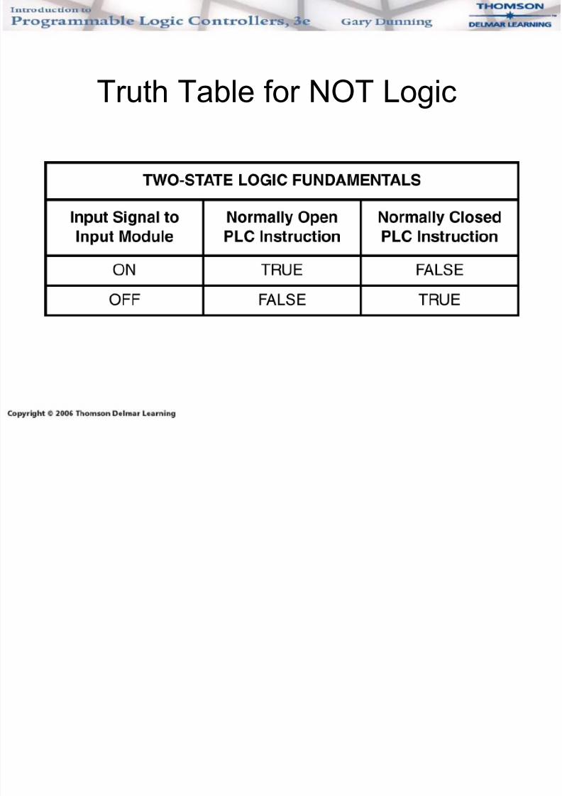
Truth Table for NOT Logic
7/29/2019 Chapter 06 Intro to Logic
http://slidepdf.com/reader/full/chapter-06-intro-to-logic 33/37
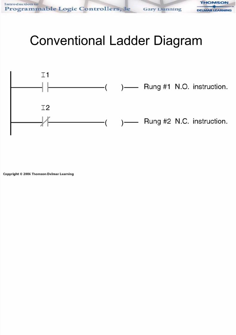
Conventional Ladder Diagram
7/29/2019 Chapter 06 Intro to Logic
http://slidepdf.com/reader/full/chapter-06-intro-to-logic 34/37
PLC Representation of
N.O. and N.C. Instructions• All PLCs use the standard normally open
(N.O.) and normally closed (N.C.)
instructions.• Different manufacturers use different names
for the instructions.
7/29/2019 Chapter 06 Intro to Logic
http://slidepdf.com/reader/full/chapter-06-intro-to-logic 35/37
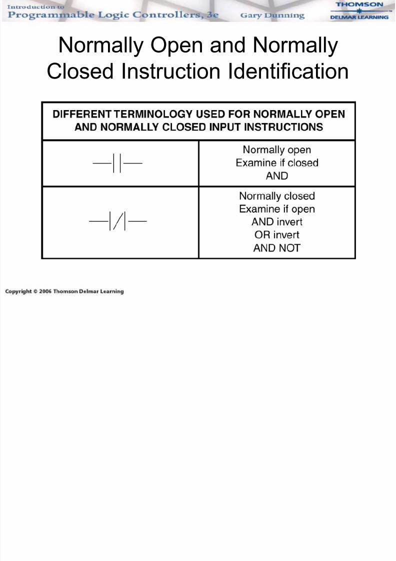
Normally Open and Normally
Closed Instruction Identification
7/29/2019 Chapter 06 Intro to Logic
http://slidepdf.com/reader/full/chapter-06-intro-to-logic 36/37
Combination AND-OR Logic
• Input devices can be combined in series
(ANDed) and also in parallel (ORed) on a
PLC ladder rung.• Instructions are programmed to provide the
proper input conditions for your application.
• This is called combination AND-OR logic.
7/29/2019 Chapter 06 Intro to Logic
http://slidepdf.com/reader/full/chapter-06-intro-to-logic 37/37
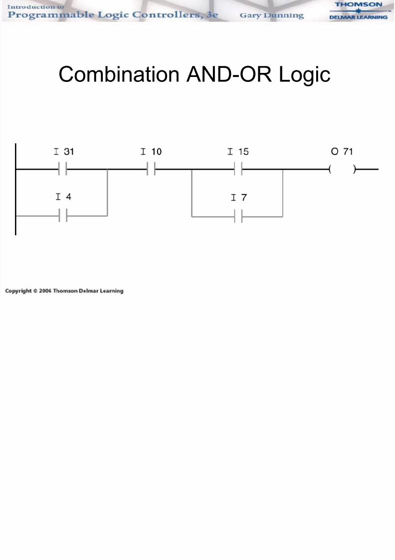
Combination AND-OR Logic