Embed Size (px)
DESCRIPTION
Engg mechanics
Citation preview
CHAPTER-1
Primary Factors of Engineering Mechanics
1.1 ENGINEERING MECHANICS
Engineering Mechanics is that branch of science, which deals the action of the forces on the rigid bodies. Everywhere we feel the application of Mechanics, such as in railway station, where we seen the railway bridge, A car moving on the road, or simply we are running on the road. Everywhere we saw the application of mechanics.
1.2 BASICS OF MECHANICS
SCIENCE, ENGINEERING AND MECHANICS
Science is nothing but gaining knowledge through appropriate laws and results from experiments.
Engineering is the application of results obtained through experiments, laws and principles for obtaining desired phenomenon.
Mechanics is the science which deals with the behavior of bodies at rest or in motion under the action of external forces.
1.3 WHY DO WE STUDY MECHANICS?
For each and every engineer, the knowledge of mechanics is most important because of the following reasons.
1. Design of mechanisms and simple machinery used in day to day life requires the knowledge of mechanics, in fact; it is the most fundamental subject in engineering.
2. Mechanics plays a basic part, in physics and astronomy, contributing to our knowledge of the working of nature.
3. With the knowledge of mechanics, any person can solve any problem by applying his knowledge with fair idea of the logical structure.
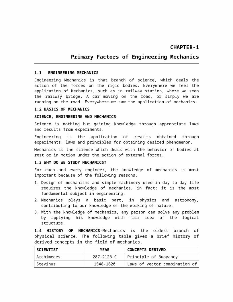
1.4 HISTORY OF MECHANICS-Mechanics is the oldest branch of physical science. The following table gives a brief history of derived concepts in the field of mechanics.
SCIENTIST YEAR CONCEPTS DERIVED
Archimedes 287-212B.C Principle of Buoyancy
Stevinus 1548-1620 Laws of vector combination of forces
Galileo 1564-1642 Experiments with falling stone
Newton 1642-1727 Laws of motion
Guillaume 1699 Empirical laws of friction
Amonton Einstein 1878-1955 Relativity theory
2/Engineering mechanics-a simple approach
1.5 IMPORTANT APPLICATION OF ENGINEERING MECHANICS
Some of the important applications of engineering mechanics are as follows.
1. Working principle of engines.2. External forces acting on a ship or boat in water.3. Study of missiles, aero planes etc.4. The forces developed in trusses and frames to resist the wing load and other
external forces.
1.6 LAWS OF MECHANICS The following laws are considered to be the foundations of mechanics;
1. Newton’ first law of motion (OR) Law of inertia.2. Newton’ second law of motion (OR) Law of force.3. Newton’ third law of motion (OR) Law of reaction.4. Law of universal gravitation.5. Parallelogram law of forces.6. Law of transmissibility of forces.
Matter is anything that occupies space, possesses mass offers resistance to any stress, example Iron, stone, air, Water.
Particle, A body of negligible dimension is called a particle. But a particle has mass. A body consists of a No. of particle, it has definite shape.
A rigid body may be defined as the combination of a large no. of particles, which occupy fixed position with respect to another, both before and after applying a load.
Or, a rigid body may be defined as a body, which can retain its shape and size even if subjected to some external forces. In actual practice, nobody is perfectly rigid. But for the sake of simplicity, we take the bodies as rigid bodies.
An elastic body is that which regain its original shape after removal of the external loads.
The basic difference between a rigid body and an elastic body is that the rigid body doesn’t change its shape and size before and after application of a force, while an elastic body may change its shape and size after application of a load, and again regain its shape after removal of the external loads.
Space: The geometric region occupied by bodies called space.
Motion when a body changes its position with respect to other bodies, then body is called as to be in motion.
Mass: The properties of matter by which the action of one body can be
compared with that of another are defined as mass.
Where, = Density of body and v = Volume of the body
Primary Factors of Engineering Mechanics/3
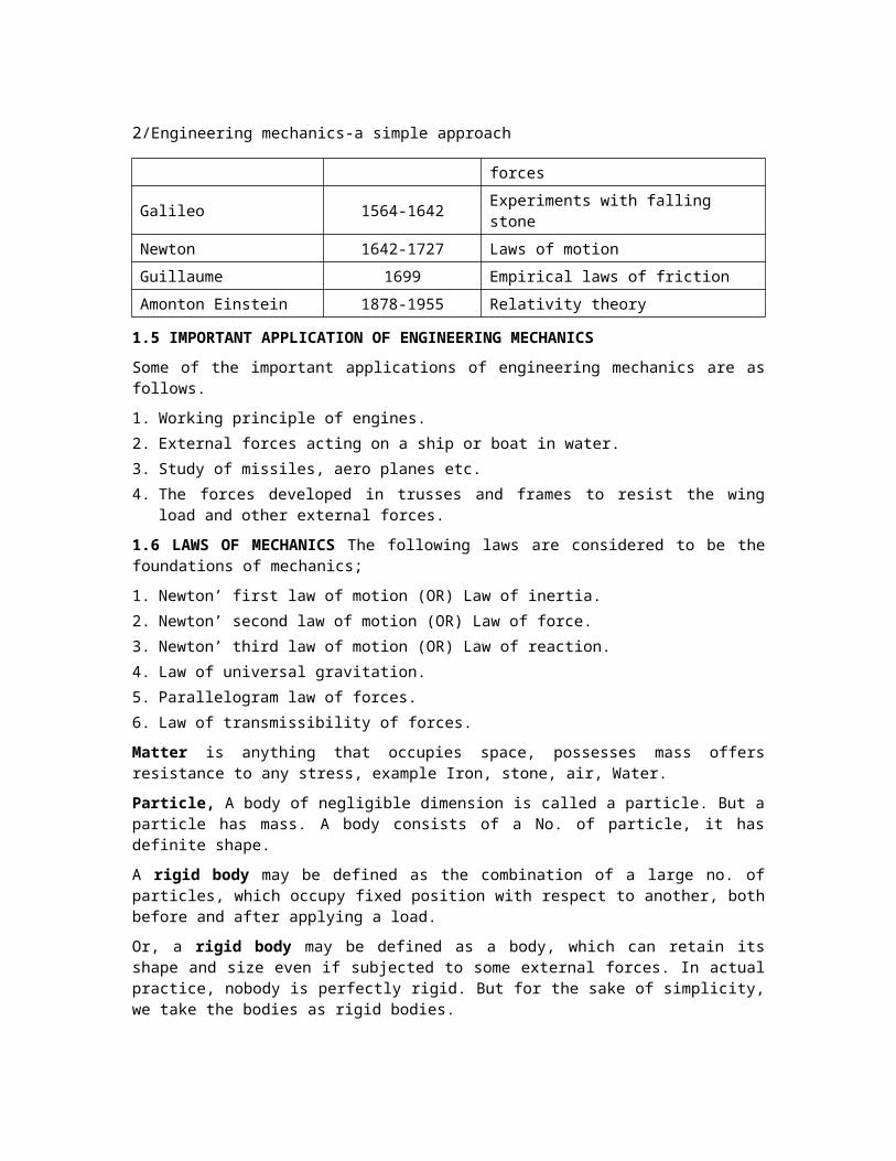
Weight of a body is the force with which the body is attracted towards the center of the earth.
S.I. Units S.I. stands for “System International Units”. There are three basic quantities in S.I. Systems as concerned to engineering Mechanics as given below:
Sl.No. Quantity Basic Unit Notation
1 Length Meter m
2 Mass Kilogram kg
3 Time Second s
Meter: It is the distance between two given parallel lines engraved upon the polished surface of a platinum-Iridium bar, kept at 00C at the “International Bureau of Weights and Measures” at Serves, near Paris.
Kilogram: It is the mass of a particular cylinder made of Platinum Iridium kept at “International Bureau of Weights and Measures” at Serves, near Paris.
Second: It is 1/ (24 × 60 × 60) Th of the mean solar day. A solar day is defined as the time interval between the instants at which the sun crosses the meridian on two consecutive days. With the help of these three basic units there are several units are derived as given below.
1.7 NEWTON'S LAW OF MOTION
1-Newton: It is magnitude of force, which develops an acceleration of 1 m/s2 in 1 kg mass of the body.
The entire subject of rigid body mechanics is based on three fundamental law of motion given by an American scientist Newton.
Newton’s first law of motion: A particle remains at rest (if originally at rest) or continues to move in a straight line (If originally in motion) with a constant speed. If the resultant force acting on it is Zero.
Newton's second law of motion: If the resultant force acting on a particle is not zero, then acceleration of the particle will be proportional to the resultant
force and will be in the direction of this force i.e;
Newton's s third law of motion: The force of action and reaction between interacting bodies are equal in magnitude, opposite in direction and have the same line of action.
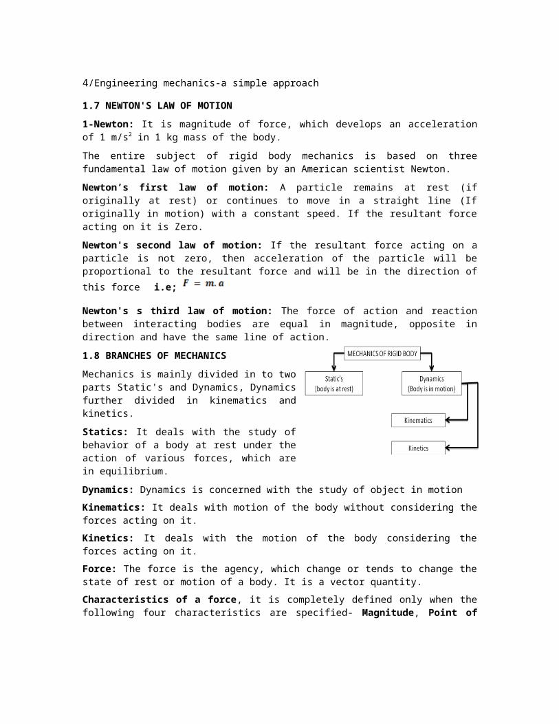
1.8 BRANCHES OF MECHANICS
Mechanics is mainly divided in to two parts Static's and Dynamics, Dynamics further divided in kinematics and kinetics.
Statics: It deals with the study of behavior of a body at rest under the action of various forces, which are in equilibrium.
4/Engineering mechanics-a simple approach
Dynamics: Dynamics is concerned with the study of object in motion
Kinematics: It deals with motion of the body without considering the forces acting on it.
Kinetics: It deals with the motion of the body considering the forces acting on it.
Force: The force is the agency, which change or tends to change the state of rest or motion of a body. It is a vector quantity.
Characteristics of a force, it is completely defined only when the following four characteristics are specified- Magnitude, Point of application, Line of action and Direction or “The action of one body on another body is defined as force”.
In engineering mechanics, applied forces are broadly divided in to two types; Tensile and compressive force.
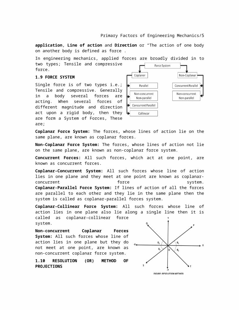
1.9 FORCE SYSTEM
Single force is of two types i.e.; Tensile and compressive. Generally in a body several forces are acting. When several forces of different magnitude and direction act upon a rigid body, then they are form a System of Forces, These are;
Coplanar Force System: The forces, whose lines of action lie on the same plane, are known as coplanar forces.
Non-Coplanar Force System: The forces, whose lines of action not lie on the same plane, are known as non-coplanar force system.
Concurrent Forces: All such forces, which act at one point, are known as concurrent forces.
Coplanar-Concurrent System: All such forces whose line of action lies in one plane and they meet at one point are known as coplanar-concurrent force system. Coplanar-Parallel Force System: If lines of action of all the forces are parallel to each other and they lie in the same plane then the system is called as coplanar-parallel forces system.
Coplanar-Collinear Force System: All such forces whose line of action lies in one plane also lie along a single line then it is called as coplanar-collinear force system.
Non-concurrent Coplanar Forces System: All such forces whose line of action lies in one plane but they do not meet at one point, are known as non-concurrent coplanar force system.
1.10 RESOLUTION (OR) METHOD OF PROJECTIONS
Primary Factors of Engineering Mechanics/5
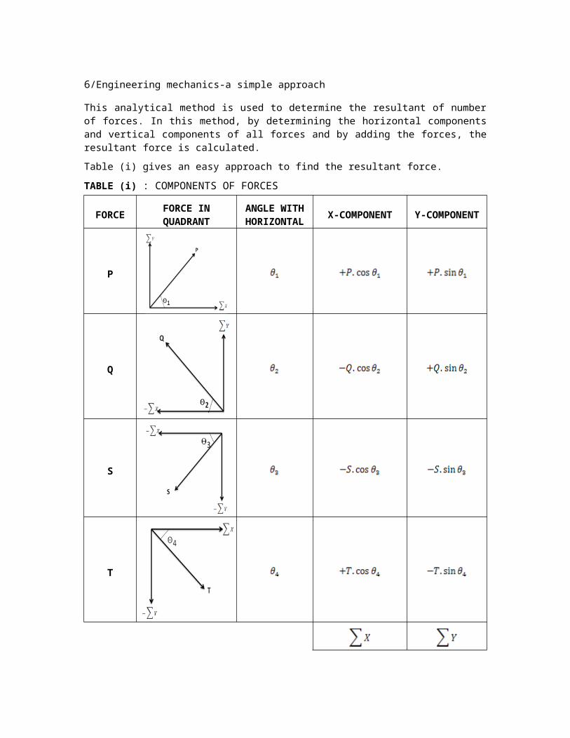
This analytical method is used to determine the resultant of number of forces. In this method, by determining the horizontal components and vertical components of all forces and by adding the forces, the resultant force is calculated.
Table (i) gives an easy approach to find the resultant force.
TABLE (i) : COMPONENTS OF FORCES
FORCE FORCE IN QUADRANT
ANGLE WITH
HORIZONTAL
X-COMPONENTY-
COMPONENT
P
Q
S
T
6/Engineering mechanics-a simple approach
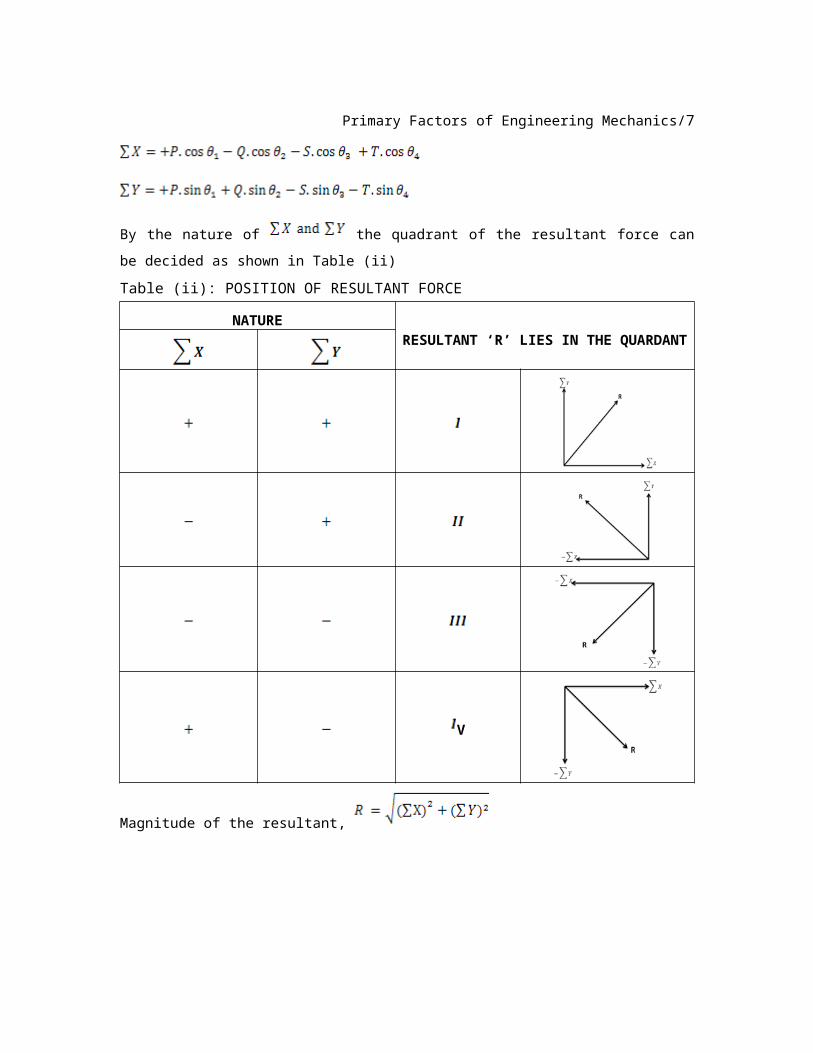
By the nature of the quadrant of the resultant force can be decided as
shown in Table (ii)
Table (ii): POSITION OF RESULTANT FORCE
NATURERESULTANT ‘R’ LIES IN THE
QUARDANT
V
Magnitude of the resultant,
Angle of the resultant with horizontal,
1.11 RESOLUTION OF FORCE
Primary Factors of Engineering Mechanics/7
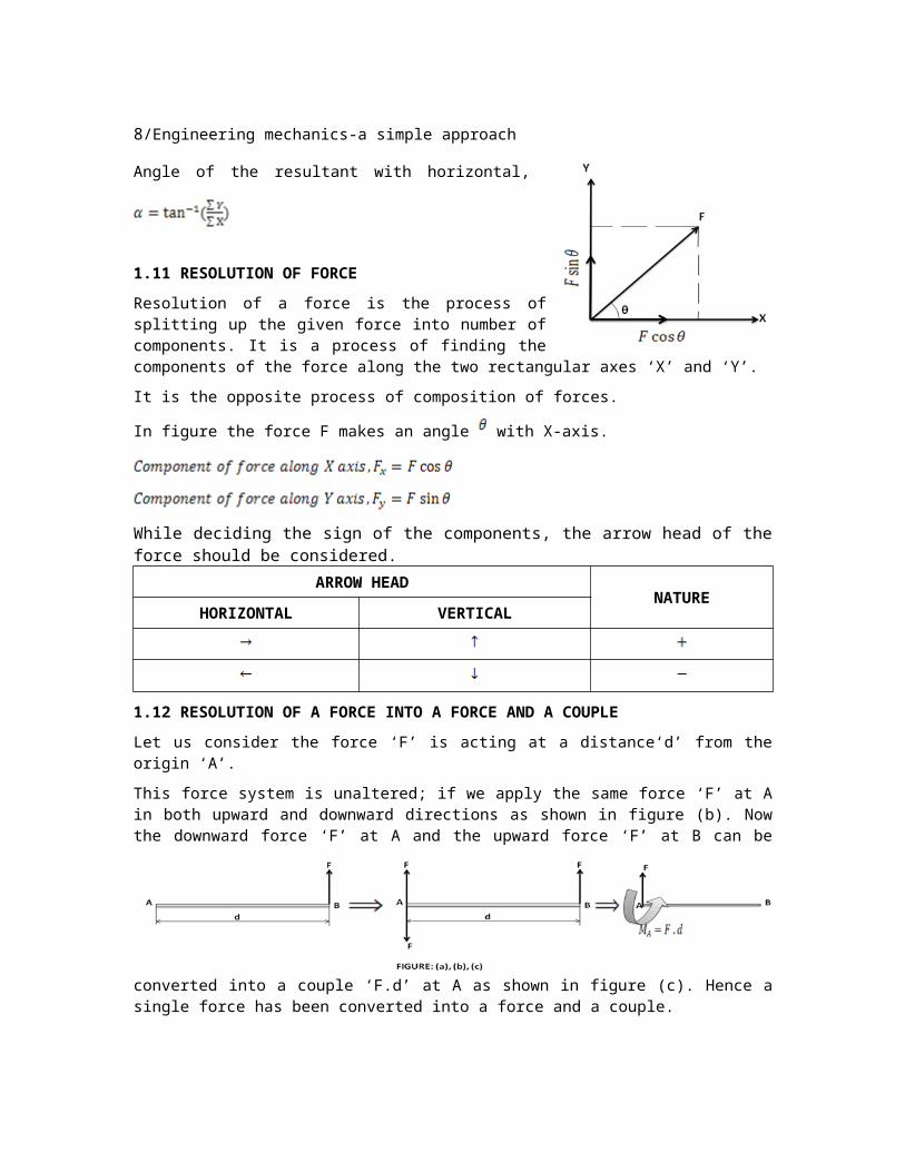
Resolution of a force is the process of splitting up the given force into number of components. It is a process of finding the components of the force along the two rectangular axes ‘X’ and ‘Y’.
It is the opposite process of composition of forces.
In figure the force F makes an angle with X-axis.
While deciding the sign of the components, the arrow head of the force should be considered.ARROW HEAD
NATUREHORIZONTAL VERTICAL
1.12 RESOLUTION OF A FORCE INTO A FORCE AND A COUPLE
Let us consider the force ‘F’ is acting at a distance‘d’ from the origin ‘A’.
This force system is unaltered; if we apply the same force ‘F’ at A in both upward and downward directions as shown in figure (b). Now the downward force ‘F’ at A and the upward force ‘F’ at B can be converted into a couple ‘F.d’ at A as shown in figure (c). Hence a single force has been converted into a force and a couple.
1.13 SCALAR AND VECTOR QUANTITIES
All physical quantities can be classified in to two broad categories.
Scalar Quantities and Vector Quantities; SCALAR QUANTITIES VECTOR QUANTITIES
A quantity is said to be scalar if it is specified by magnitude only.
A quantity is said to be vector if it is specified by magnitude and direction.
Scalars can be added or subtracted arithmetically
Vectors cannot be added arithmetically.
Examples; Length, mass, time, distance, area, volume, density, temperature, speed, work, energy etc
Example; Force, displacement, velocity, acceleration, moment, momentum, impact etc.
1.14 REPRESENTATION OF A VECTOR
8/Engineering mechanics-a simple approach
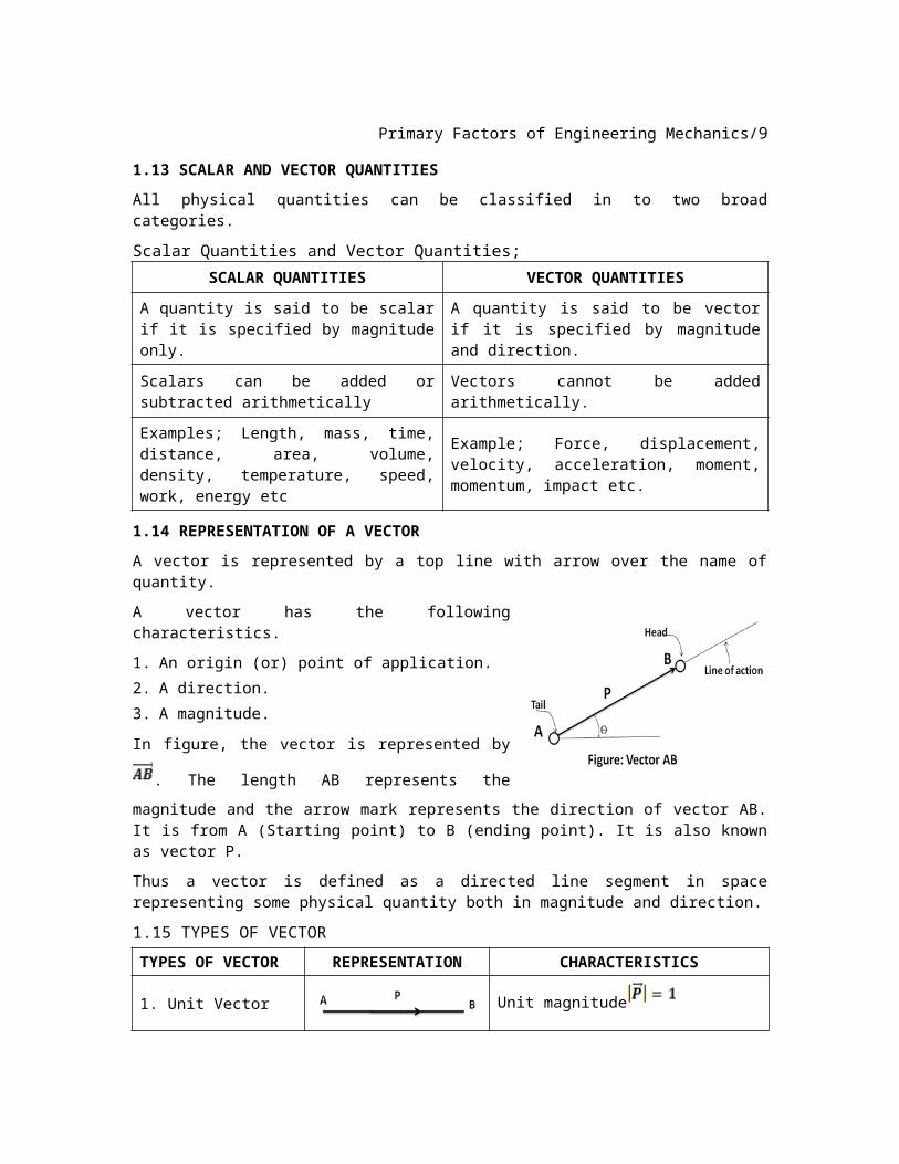
A vector is represented by a top line with arrow over the name of quantity.
A vector has the following characteristics.
1. An origin (or) point of application. 2. A direction.3. A magnitude.
In figure, the vector is represented by . The
length AB represents the magnitude and the arrow mark represents the direction of vector AB. It is from A (Starting point) to B (ending point). It is also known as vector P.
Thus a vector is defined as a directed line segment in space representing some physical quantity both in magnitude and direction.
1.15 TYPES OF VECTOR
TYPES OF VECTOR
REPRESENTATION CHARACTERISTICS
1. Unit Vector Unit magnitude
2. Equal VectorEqual magnitude, same direction
and parallel to each other.
3. Like Vector
Unequal magnitude, same direction and parallel to each
other.
4. Sliding Vector (Transmissible Vector)
It can be moved anywhere but should maintain same direction and magnitude.
5. Free Vector
The action of free vector is not confined to a unique line in space. The vector may be moved anywhere in the space without rotation.
6. Fixed Vector (Or) Bound Vector
Must remain at the same point of application.To maintain the equilibrium a
reaction will be developed at
the other end.
Primary Factors of Engineering Mechanics/9
7. Zero Vector (Or) Null Vector
It is obtained when a vector is
subtracted from itself.
1.16 VECTOR OPERATIONS
1.16. a. ADDITION AND SUBTRATION OF TWO PARALLEL VECTORS
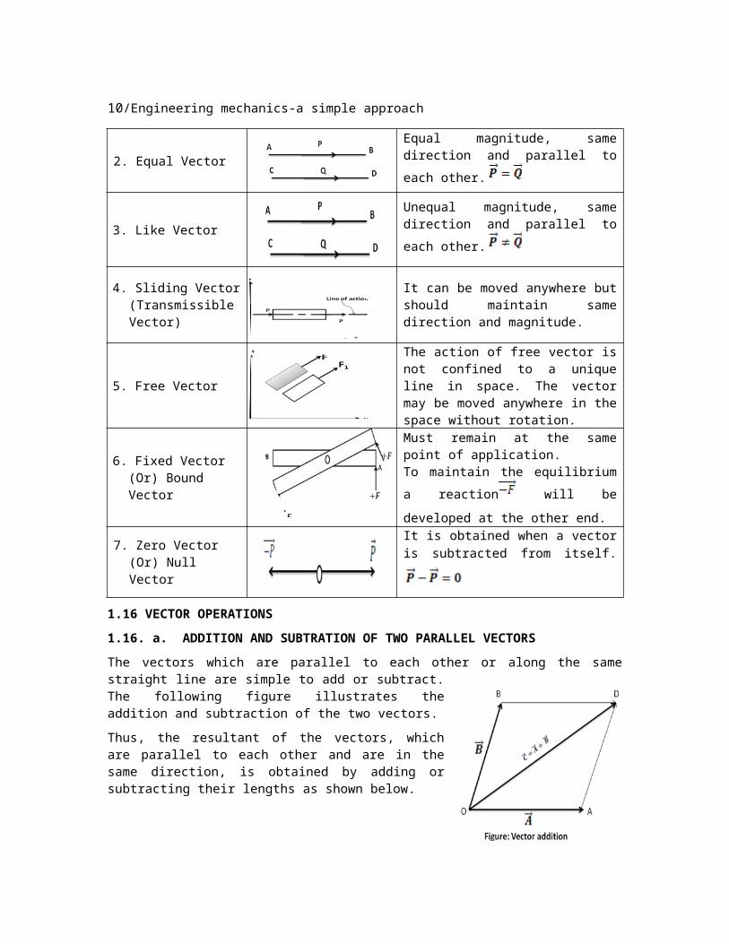
The vectors which are parallel to each other or along the same straight line are simple to add or subtract. The following figure illustrates the addition and subtraction of the two vectors.
Thus, the resultant of the vectors, which are parallel to each other and are in the same direction, is obtained by adding or subtracting their lengths as shown below.
In case of subtraction, the direction of the resultant vector is in the direction of the bigger vector.
Let us consider two vectors originating from
point ‘O’. Construct a parallelogram OADB for these
vectors a shown in figure. The diagonal of the parallelogram represents the
vectors which is the addition of the two vectors
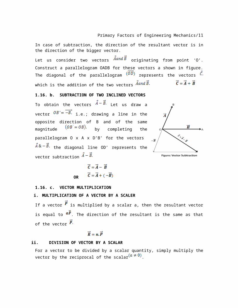
1.16. b. SUBTRACTION OF TWO INCLINED VECTORS
To obtain the vectors Let us draw a vector
i.e.; drawing a line in the opposite direction
of B and of the same magnitude by
completing the parallelogram O x A x D’B’ for the
vectors the diagonal line OD’ represents the
vector subtraction
OR
1.16. c. VECTOR MULTIPLICATIONi. MULTIPLICATION OF A VECTOR BY A SCALER
If a vector is multiplied by a scalar a, then the resultant vector is equal to .
The direction of the resultant is the same as that of the vector
10/Engineering mechanics-a simple approach
ii. DIVISION OF VECTOR BY A SCALAR
For a vector to be divided by a scalar quantity, simply multiply the vector by the
reciprocal of the scalar .
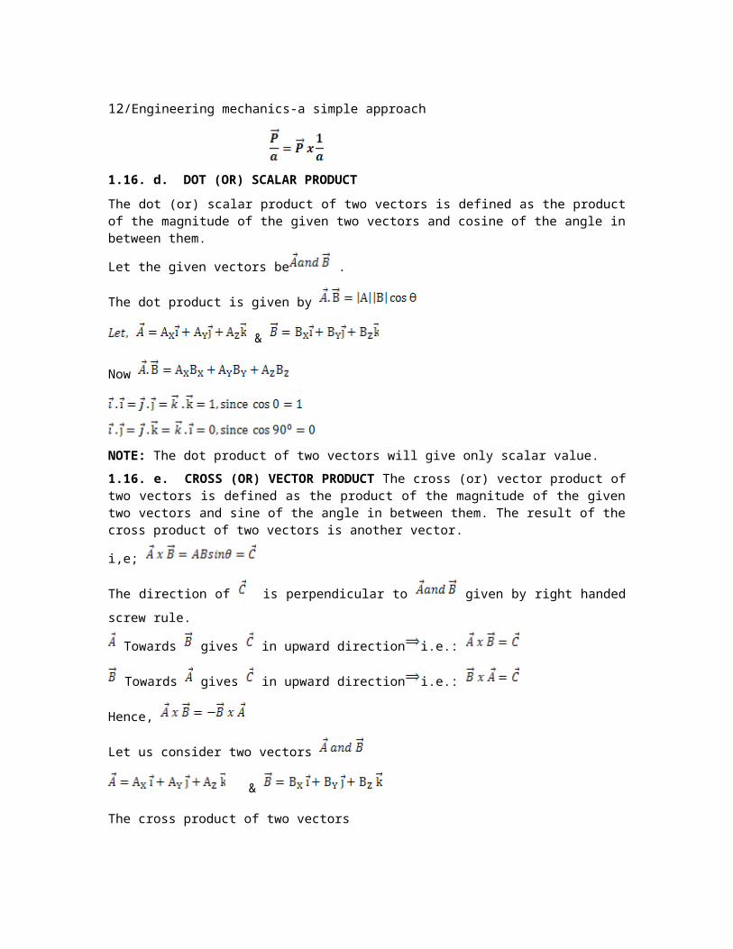
1.16. d. DOT (OR) SCALAR PRODUCT
The dot (or) scalar product of two vectors is defined as the product of the magnitude of the given two vectors and cosine of the angle in between them.
Let the given vectors be .
The dot product is given by
&
Now
NOTE: The dot product of two vectors will give only scalar value.
1.16. e. CROSS (OR) VECTOR PRODUCT The cross (or) vector product of two vectors is defined as the product of the magnitude of the given two vectors and sine of the angle in between them. The result of the cross product of two vectors is another vector.
i,e;
The direction of is perpendicular to given by right handed screw rule.
Towards gives in upward direction i.e.:
Towards gives in upward direction i.e.:
Hence,
Let us consider two vectors
&
Primary Factors of Engineering Mechanics/11
The cross product of two vectors
Since
Another method to evaluate the cross product is using matrix determinant.
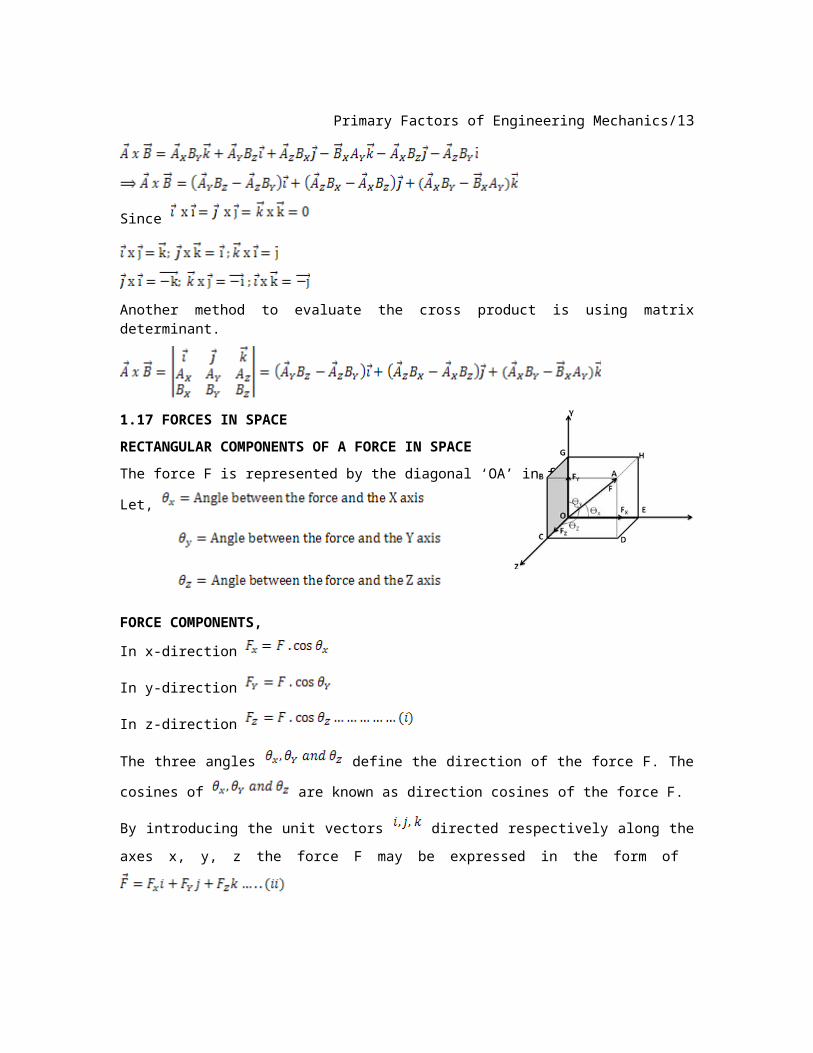
1.17 FORCES IN SPACE
RECTANGULAR COMPONENTS OF A FORCE IN SPACE
The force F is represented by the diagonal ‘OA’ in figure.
Let,
FORCE COMPONENTS,
In x-direction
In y-direction
In z-direction
The three angles define the direction of the force F. The cosines of
are known as direction cosines of the force F.
By introducing the unit vectors directed respectively along the axes x, y, z
the force F may be expressed in the form of
Substituting the scalar components in equation (ii)
12/Engineering mechanics-a simple approach
The above equation shows that the force may be expressed as product of the
scalar F and of the vector.
Let us consider unit vector along the line of action of F.
The magnitude of is equal to 1.
By substituting (iv) into (iii)
Where
When the components of force are given the magnitude ‘F’ of the
force is obtained from (ii) and (v) by equating the component of I, j, k
1.18 POSITION VECTOR
The position vector of a point A with respect to origin ‘O’ is the vector , It is
represented by . The position vector of a point (x, y, z) in space is written as
The magnitude of the position vector
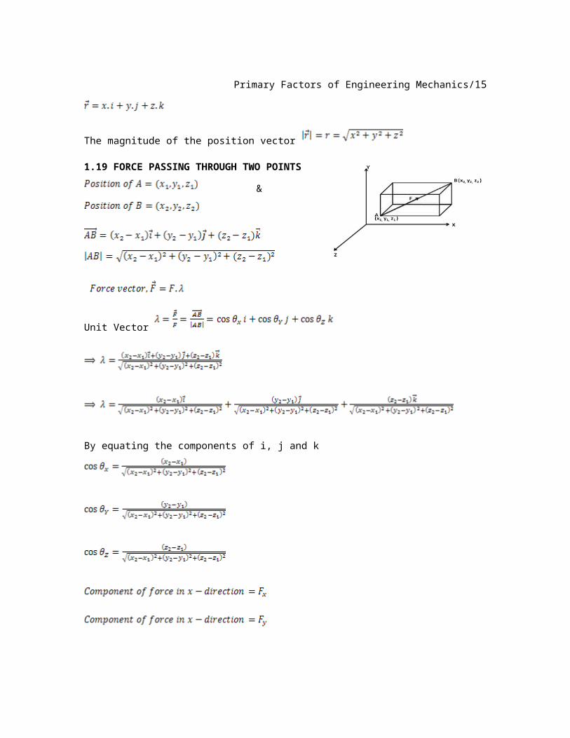
1.19 FORCE PASSING THROUGH TWO POINTS
Primary Factors of Engineering Mechanics/13
&
Unit Vector
By equating the components of i, j and k
1.20 FORCE ACTING FROM THE ORIGIN
The force starts from the origin.
14/Engineering mechanics-a simple approach
Unit Vector
And hence,
1.21 ADDITION OF CONCURRENT FORCES IN SPACE
The resultant ‘R’ of a concurrent force system in space is determined by
summing their rectangular components.
By equating the components of I, j, k.
,
The magnitude of Resultant,
The angle it forms with the axes of co-ordinate
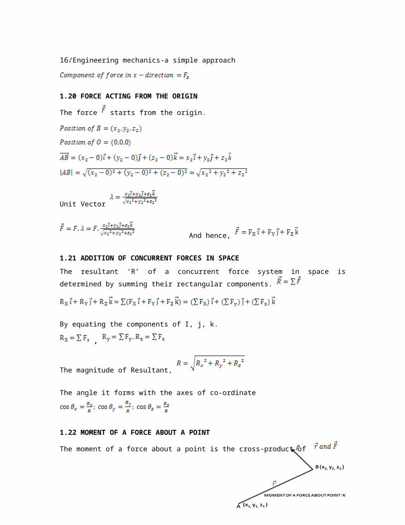
1.22 MOMENT OF A FORCE ABOUT A POINT
The moment of a force about a point is the cross-product of
i.e;
We know that,
And
Putting the value in above equation (i)
Primary Factors of Engineering Mechanics/15
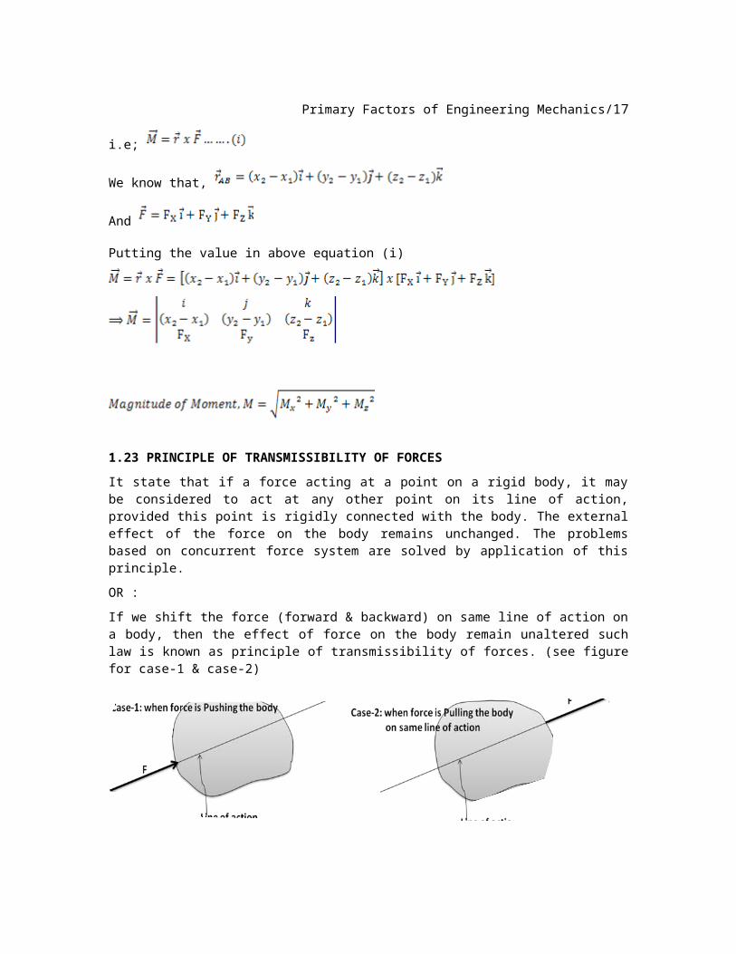
1.23 PRINCIPLE OF TRANSMISSIBILITY OF FORCES
It state that if a force acting at a point on a rigid body, it may be considered to act at any other point on its line of action, provided this point is rigidly connected with the body. The external effect of the force on the body remains unchanged. The problems based on concurrent force system are solved by application of this principle.
OR :
If we shift the force (forward & backward) on same line of action on a body, then the effect of force on the body remain unaltered such law is known as principle of transmissibility of forces. (see figure for case-1 & case-2)
LIMITATION OF PRINCIPLE OF TRANSMISSIBILITY OF FORCES
It is used to determine only the external forces but not the internal forces in a body.
1.24 RESULTANT OF A FORCE SYSTEM
Resultant is a single force which produces the same effect as produced by number of forces jointly in a system.
There are many ways to find out the resultant of the force system. But the first thing is to see that how many forces are acting on the body?
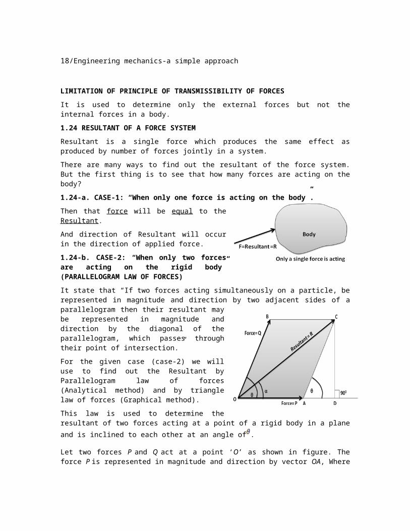
1.24-a. CASE-1: “When only one force is acting on the body”.
Then that force will be equal to the Resultant.
And direction of Resultant will occur in the direction of applied force.
16/Engineering mechanics-a simple approach
1.24-b. CASE-2: “When only two forces are acting on the rigid body” (PARALLELOGRAM LAW OF FORCES)
It state that “If two forces acting simultaneously on a particle, be represented in magnitude and direction by two adjacent sides of a parallelogram then their resultant may be represented in magnitude and direction by the diagonal of the parallelogram, which passes through their point of intersection.”
For the given case (case-2) we will use to find out the Resultant by Parallelogram law of forces (Analytical method) and by triangle law of forces (Graphical method).
This law is used to determine the resultant of two forces acting at a point of a rigid body in a plane and is inclined to each other at an
angle of .
Let two forces P and Q act at a point ‘O’ as shown in figure. The force P is represented in magnitude and direction by vector OA, Where as the force Q is represented in magnitude and direction by Vector OB, Angle between two force is
‘ ’. The resultant is denoted by vector OC in figure. Drop perpendicular from C on
OA.
Let,
Now
Primary Factors of Engineering Mechanics/17
:
Resultant R is max when the two forces collinear and in the same direction.
Resultant R is min when the two forces collinear but acting in opposite
direction.
HINT TO SOLVE THE PROBLEM:
If there is given Resultant ‘word’ in question then do not use .
If there is given Resultant ‘word’ in question then think always & immediate that how many forces are given in the question. If according to question there are TWO FORCES then use the PARALLELOGRAM LAW OF FORCES and…
For MORE THAN TWO FORCES we will use RESOLUTION OF FORCES. If there is an indication in question about the direction of resultant, then use
the equation of immediately.
If there is an indication in question about the magnitude of resultant, then use
the equation of , where is angle between two forces
P & Q.
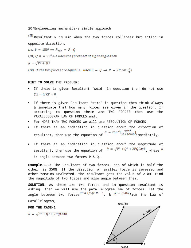
Example-1.1: The Resultant of two forces, one of which is half the other, is 350N. If the direction of smaller force is reversed and other remains unaltered, the resultant gets the value of 210N. Find the magnitude of two forces and also angle between them.
18/Engineering mechanics-a simple approach
SOLUTION: As there are two forces and in question resultant is asking, then we will use the parallelogram law of forces. Let the angle between two forces
, & From the Law of Parallelogram,
FOR THE CASE-1
…….. (i)
FOR THE CASE-2
……………….. (ii)
Adding (i) & (ii), we get
Example-1.2: Two forces equal to 2P and P act on a particle. If the first force be doubled and the second force is increased by 12KN, the direction of their resultant remain unaltered. Find the value of P.
SOLUTION: In both cases direction of resultant remain unchanged, so we used
the formula,
Primary Factors of Engineering Mechanics/19
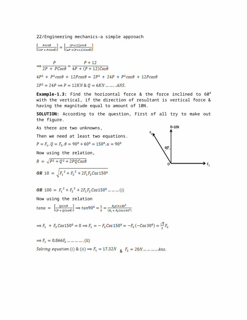
Example-1.3: Find the horizontal force & the force inclined to 600 with the vertical, if the direction of resultant is vertical force & having the magnitude equal to amount of 10N.
SOLUTION: According to the question, First of all try to make out the figure.
As there are two unknowns,
Then we need at least two equations.
Now using the relation,
Now using the relation
&
20/Engineering mechanics-a simple approach
Example-1.4: Find the magnitude of two forces such that if they act at right
angle their resultant is , while they act at an angle of 600, their resultant is
.
SOLUTION: Let the two forces be P and Q, and their resultant be ‘R’
Since
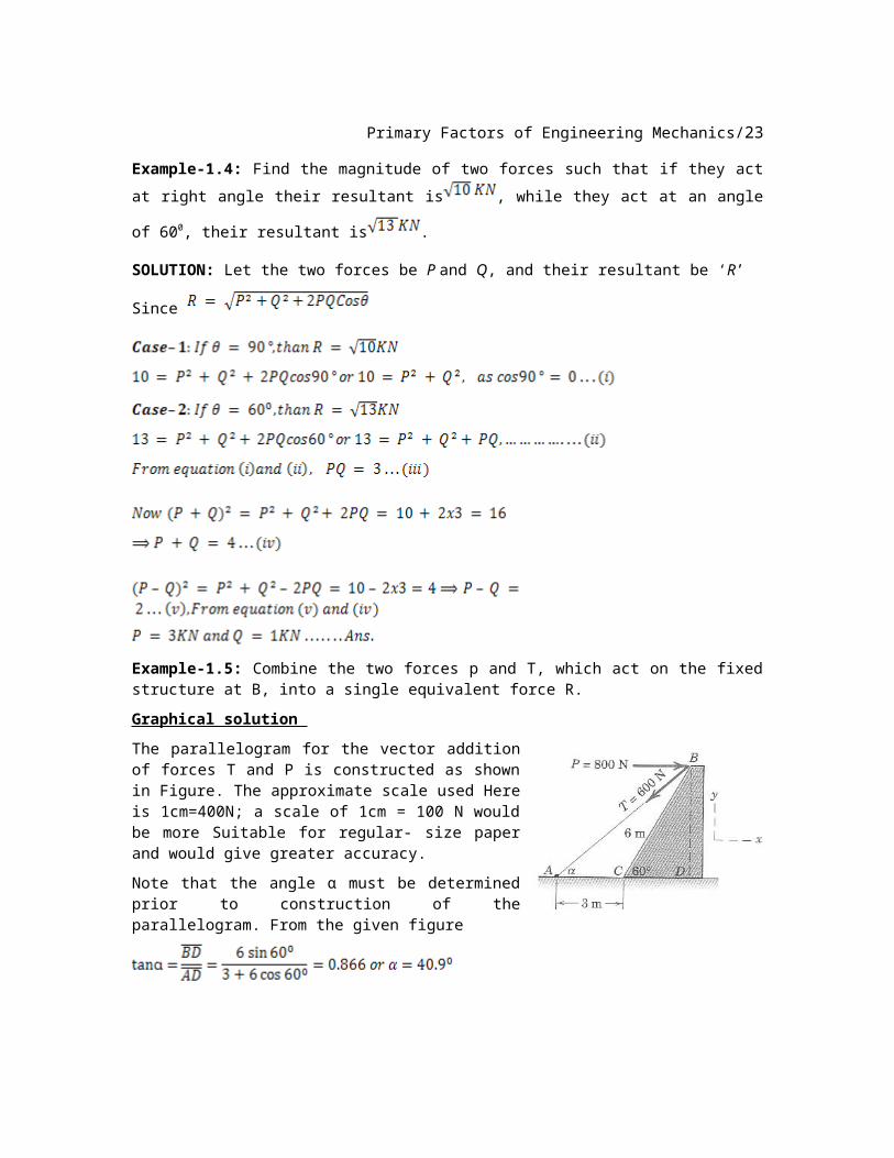
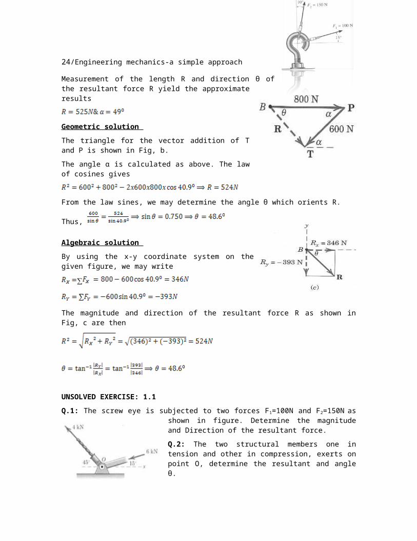
Example-1.5: Combine the two forces p and T, which act on the fixed structure at B, into a single equivalent force R.
Graphical solution
The parallelogram for the vector addition of forces T and P is constructed as shown in Figure. The approximate scale used Here is 1cm=400N; a scale of 1cm = 100 N would be more Suitable for regular- size paper and would give greater accuracy.
Note that the angle α must be determined prior to construction of the parallelogram. From the given figure
Measurement of the length R and direction θ of the resultant force R yield the approximate results
Primary Factors of Engineering Mechanics/21
Geometric solution
The triangle for the vector addition of T and P is shown in Fig, b.
The angle α is calculated as above. The law of cosines gives
From the law sines, we may determine the angle θ which orients R.
Thus,
Algebraic solution
By using the x-y coordinate system on the given figure, we may write
∑
The magnitude and direction of the resultant force R as shown in Fig, c are then
UNSOLVED EXERCISE: 1.1
Q.1: The screw eye is subjected to two forces F1=100N and F2=150N as shown in figure. Determine the magnitude and Direction of the resultant force.
Q.2: The two structural members one in tension and other in compression, exerts on point O, determine the resultant and angle θ.
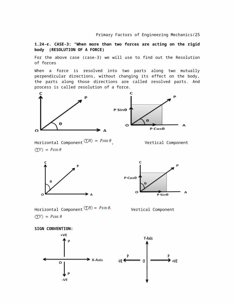
1.24-c. CASE-3: “When more than two forces are acting on the rigid body” (RESOLUTION OF A FORCE)
For the above case (case-3) we will use to find out the Resolution of forces
When a force is resolved into two parts along two mutually perpendicular directions, without changing its effect on the body, the parts along those directions are called resolved parts. And process is called resolution of a force.
22/Engineering mechanics-a simple approach
Horizontal Component , Vertical Component
Horizontal Component Vertical Component
SIGN CONVENTION:
Take
Upward forces as positive, downward force as negative, leftward force as negative and rightward force as positive.
1.25 EVALUATION OF RESULTANT
The steps are as;
1. Count Total No. of forces acting on the body (if more than two forces then start resolution)
2. First resolved all the forces in horizontal and vertical direction.3. Take upward forces as positive, down force as negative, leftward force as
negative and rightward force as positive,
4. Take sum of all horizontal parts i.e.,
Primary Factors of Engineering Mechanics/23
5. Take sum of all vertical parts i.e.,
6. Find the resultant of the force system using,
7.
8. Find angle of resultant by using
9. Take care about sign of and .
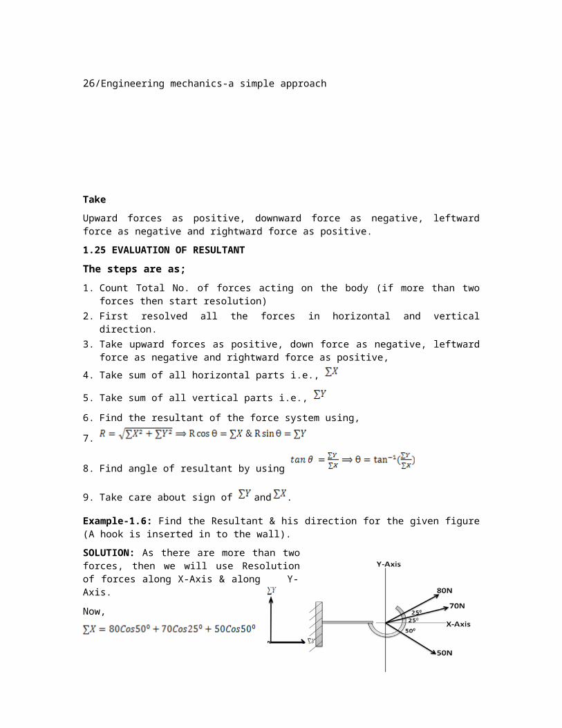
Example-1.6: Find the Resultant & his direction for the given figure (A hook is inserted in to the wall).
SOLUTION: As there are more than two forces, then we will use Resolution of forces along X-Axis & along Y-Axis.
Now,
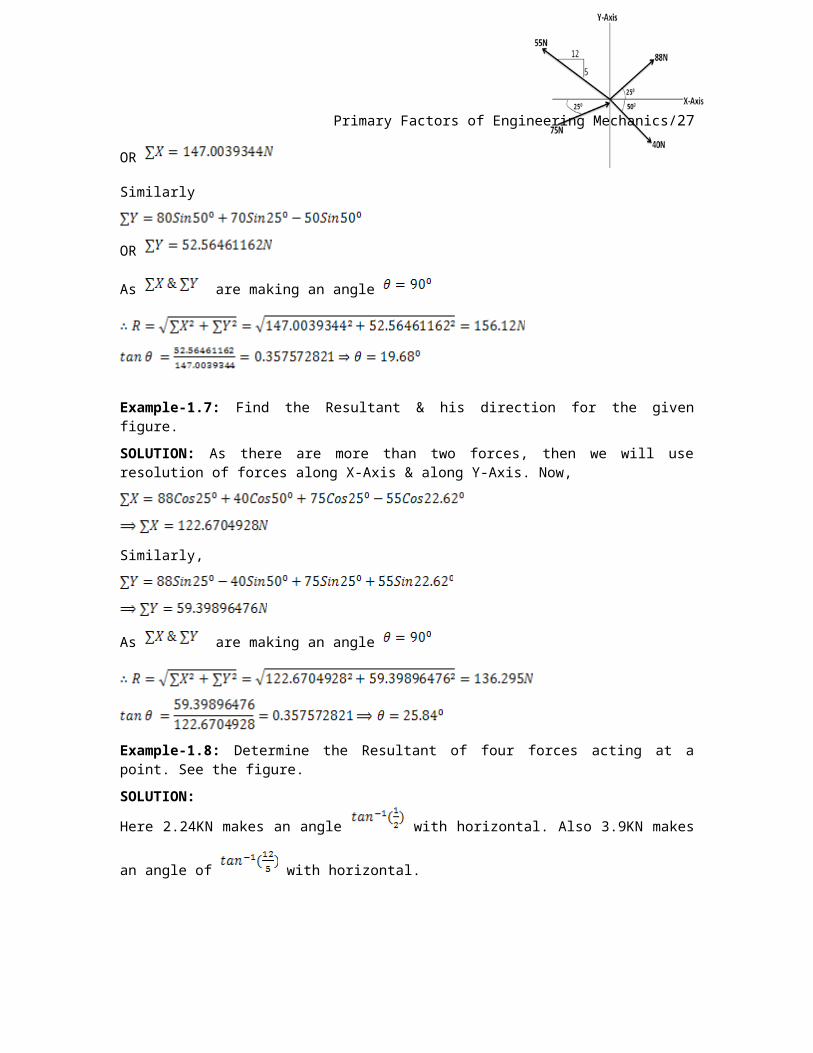
OR
Similarly
OR
As are making an angle
Example-1.7: Find the Resultant & his direction for the given figure.
SOLUTION: As there are more than two forces, then we will use resolution of forces along X-Axis & along Y-Axis. Now,
Similarly,
24/Engineering mechanics-a simple approach
As are making an angle
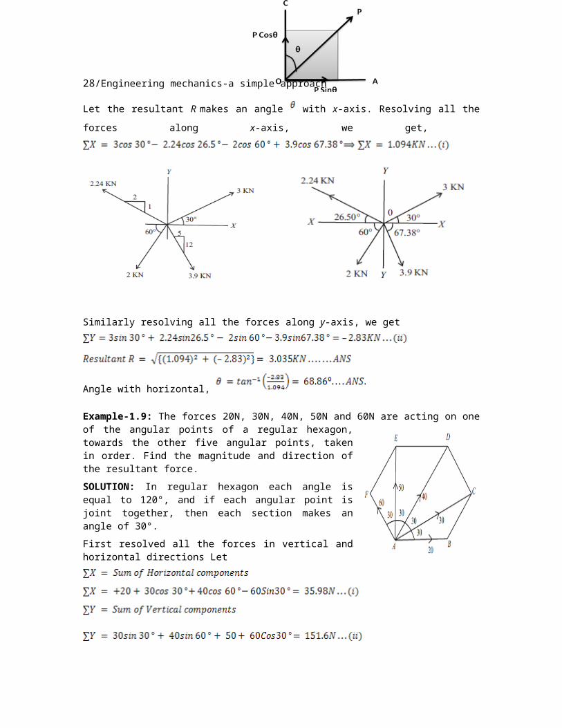
Example-1.8: Determine the Resultant of four forces acting at a point. See the figure.
Let the resultant R makes an angle with x-axis. Resolving all the forces along x-
axis, we get,
Similarly resolving all the forces along y-axis, we get
Angle with horizontal,
Example-1.9: The forces 20N, 30N, 40N, 50N and 60N are acting on one of the angular points of a regular hexagon, towards the other five angular points, taken in order. Find the magnitude and direction of the resultant force.
Primary Factors of Engineering Mechanics/25
SOLUTION: In regular hexagon each angle is equal to 120°, and if each angular point is joint together, then each section makes an angle of 30°.
First resolved all the forces in vertical and horizontal directions Let
t
Example-1.10: Four forces of magnitude P, 2P, 5P and 4P are acting at a point. Angles made by these forces with x-axis are 0°, 75°, 150° and 225° respectively. Find the magnitude and direction of resultant force.
SOLUTION: first resolved all the forces in horizontal and vertical direction
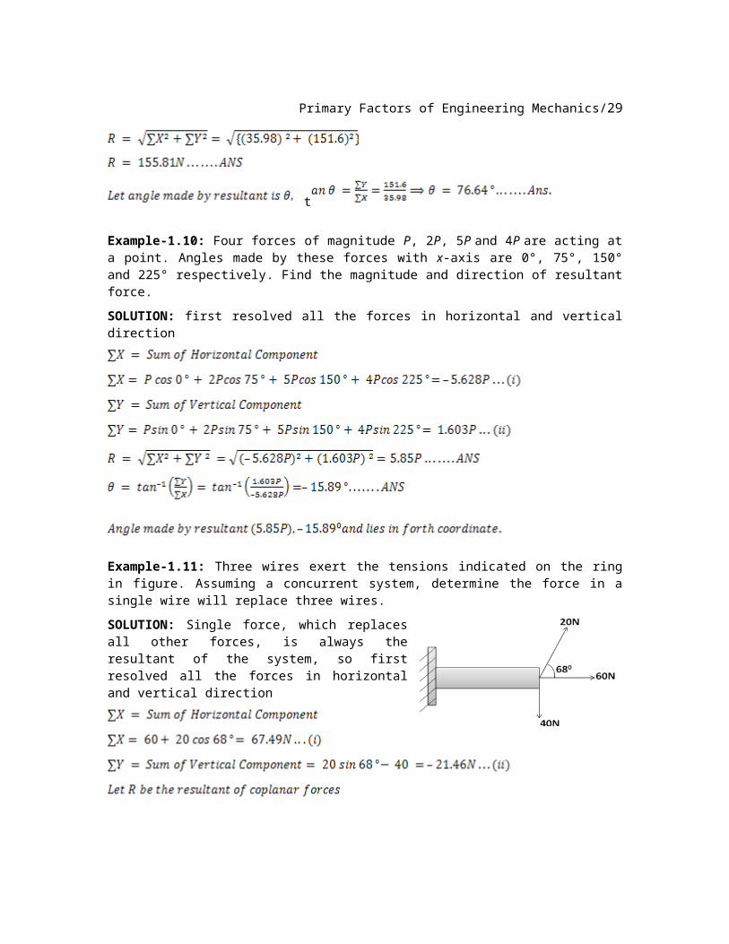
Example-1.11: Three wires exert the tensions indicated on the ring in figure. Assuming a concurrent system, determine the force in a single wire will replace three wires.
SOLUTION: Single force, which replaces all other forces, is always the resultant of the system, so first resolved all the forces in horizontal and vertical direction
26/Engineering mechanics-a simple approach
UNSOLVED EXERCISE: 1.2
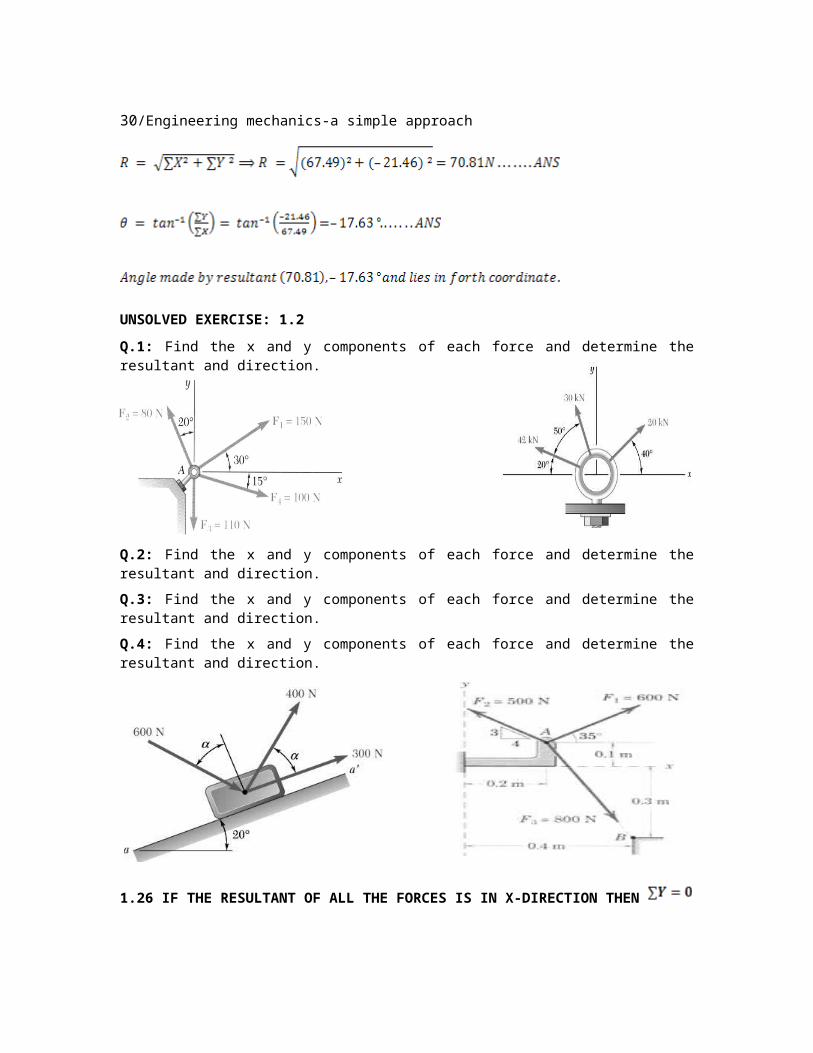
Q.1: Find the x and y components of each force and determine the resultant and direction.
Q.2: Find the x and y components of each force and determine the resultant and direction.
Q.3: Find the x and y components of each force and determine the resultant and direction.
Q.4: Find the x and y components of each force and determine the resultant and direction.
1.26 IF THE RESULTANT OF ALL THE FORCES IS IN X-DIRECTION THEN
Primary Factors of Engineering Mechanics/27
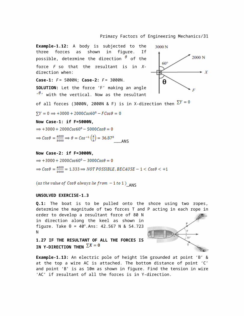
Example-1.12: A body is subjected to the three forces as shown in figure. If possible, determine the
direction of the force F so that the resultant is in
X-direction when:
Case-1: F = 5000N; Case-2: F = 3000N.
SOLUTION: Let the force ‘F’ making an angle ‘ ’
with the vertical. Now as the resultant of all forces
(3000N, 2000N & F) is in X-direction then
Now Case-1: if F=5000N,
………ANS
Now Case-2: if F=3000N,
…ANS
UNSOLVED EXERCISE-1.3
Q.1: The boat is to be pulled onto the shore using two ropes, determine the magnitude of two forces T and P acting in each rope in order to develop a resultant force of 80 N in direction along the keel as shown in figure. Take θ = 40o.Ans: 42.567 N & 54.723 N
1.27 IF THE RESULTANT OF ALL THE FORCES
IS IN Y-DIRECTION THEN
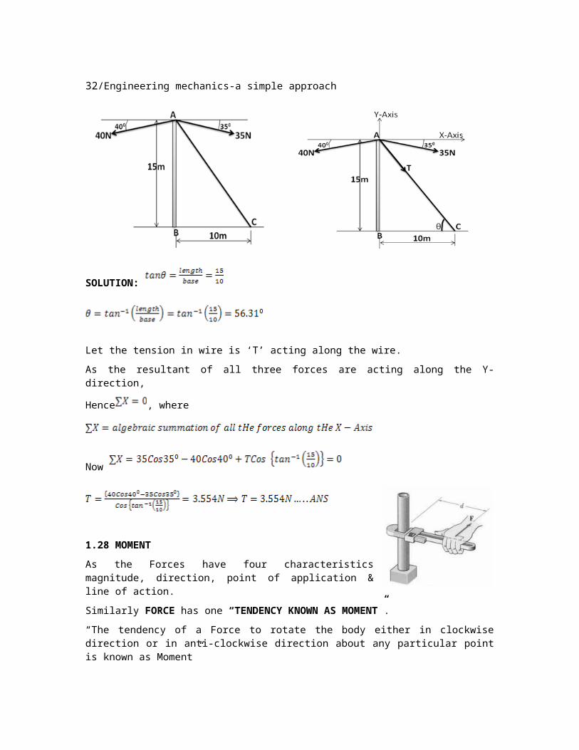
Example-1.13: An electric pole of height 15m grounded at point ‘B’ & at the top a wire AC is attached. The bottom distance of point ‘C’ and point ‘B’ is as 10m as shown in figure. Find the tension in wire ‘AC’ if resultant of all the forces is in Y-direction.
28/Engineering mechanics-a simple approach
SOLUTION:
Let the tension in wire is ‘T’ acting along the wire.
As the resultant of all three forces are acting along the Y-direction,
Hence , where
Now
1.28 MOMENT
As the Forces have four characteristics magnitude, direction, point of application & line of action.
Similarly FORCE has one “TENDENCY KNOWN AS MOMENT”.
“The tendency of a Force to rotate the body either in clockwise direction or in anti-clockwise direction about any particular point is known as Moment”
It means ki force agar Kisi body pe lagta hai to wo force us body ko ghuma dega ya phir ghumane ki koshish karega, force ki body ko rotate kerane ki aadat ko hi moment kahte hai.
Or
“Moment need the force & it taken about any particular point”
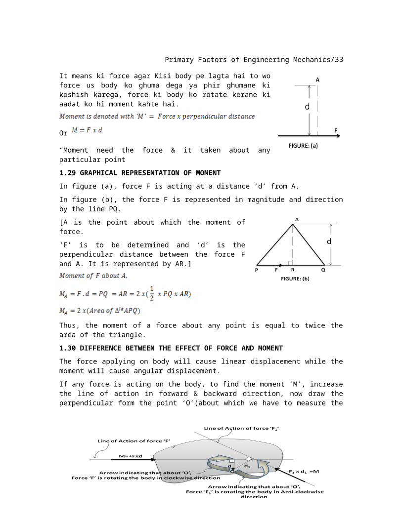
1.29 GRAPHICAL REPRESENTATION OF MOMENT
In figure (a), force F is acting at a distance ‘d’ from A.
In figure (b), the force F is represented in magnitude and direction by the line PQ.
[A is the point about which the moment of force.
Primary Factors of Engineering Mechanics/29
‘F’ is to be determined and ‘d’ is the perpendicular distance between the force F and A. It is represented by AR.]
Thus, the moment of a force about any point is equal to twice the area of the triangle.
1.30 DIFFERENCE BETWEEN THE EFFECT OF FORCE AND MOMENT
The force applying on body will cause linear displacement while the moment will cause angular displacement.
If any force is acting on the body, to find the moment ‘M’, increase the line of action in forward & backward direction, now draw the perpendicular form the point ‘O’(about which we have to measure the moment) on that line of action & measure this distance then multiply it with the amount of force. Such that
NOTE: The moment of a force can be obtained by using the following options;
1. By finding the perpendicular distance and then using the
2. By resolving the given force into rectangular components at the given position and then adding the moments due to the two components.
3. By resolving the force on X-axis where the line of action intersects the X-axis.4. By resolving the force on Y-axis where the line of action intersects the Y-axis.
5. By using the vector equation .
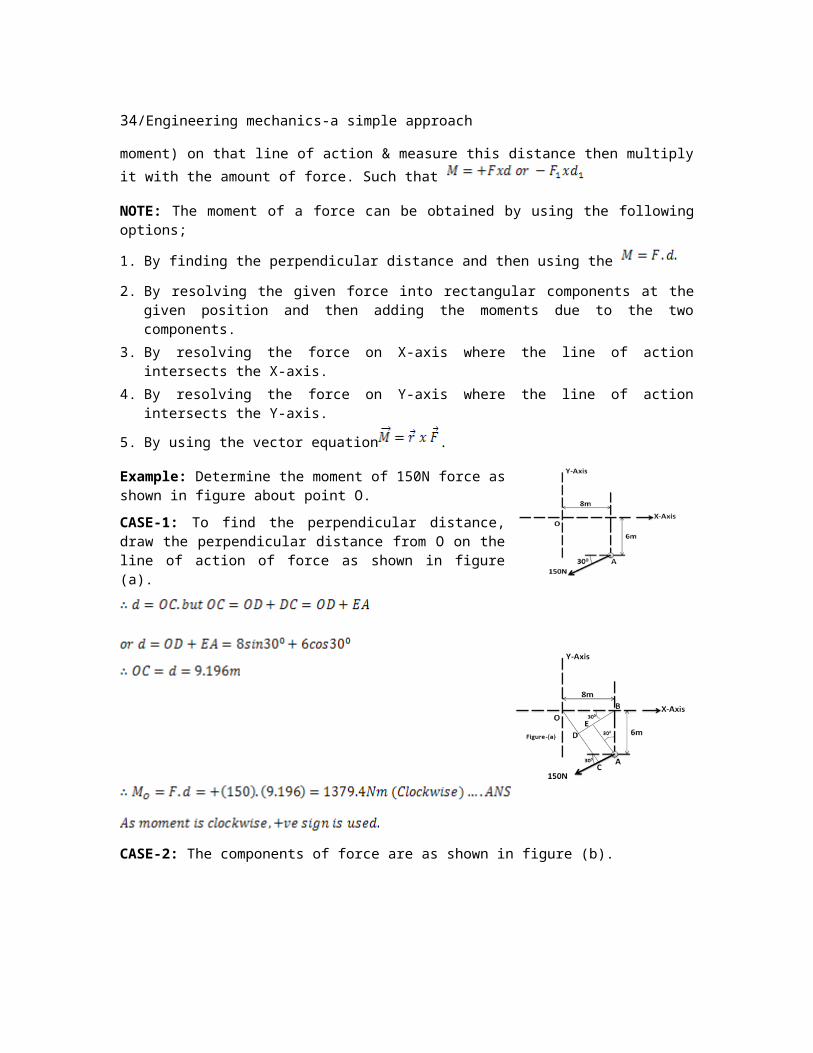
Example: Determine the moment of 150N force as shown in figure about point O.
CASE-1: To find the perpendicular distance, draw the perpendicular distance from O on the line of action of force as shown in figure (a).
30/Engineering mechanics-a simple approach
CASE-2: The components of force are as shown in figure (b).
CASE-3: When
the force is resolved on X-axis, the moment produced by the x-component about O becomes zero as its line of action passes through O. The perpendicular
distance for y-components become as shown in figure (c).
CASE-4: When the force is resolved on Y-axis, the moment produced by the y-component about O becomes zero as its line of action passes through O.
The perpendicular distance for x-components become
as shown in figure (d).
Primary Factors of Engineering Mechanics/31
CASE-5: Using vector equation
,
Moment vector in positive z-direction represents
clockwise sense of direction, hence is in positive z-
direction.
Example-1.14: Find the moment about point ‘O’ of the various force acting on the body.
SOLUTION:
Example-1.15: Find the moment about point ‘O’ of the various force acting on the body. (Hint: Resolve only forces.)
SOLUTION: First Resolve the force along X-Axis & Y-Axis.
32/Engineering mechanics-a simple approach
Example-1.16: Find the moment about point ‘O’ of the various force acting on the body. (Hint: Resolve only forces)
SOLUTION: First Resolve the force along X-Axis & Y-Axis.
The moment of both 100N forces will be zero as they are passing through the point ‘O’.
Example-1.17: Find the moment about point ‘O’ of the various force acting on the body. (Hint: Resolve forces as well as distances also.)
SOLUTION:
UNSOLVED EXERCISE-1.4
Primary Factors of Engineering Mechanics/33
Q.1: Find the moment about point ‘A’ of the force (F=200N) acting on the body. (Ans:13 .648 N anti clock wise)
Q.2: Find the moment about point ‘O’ of the various force acting on the body. (Ans: 333.92 N m clock wise)
Q.3: Find the moment about point ‘O’ of the various force acting on the body.
(Ans: 600N-m, 1.12N-m, 518N-m)
34/Engineering mechanics-a simple approach
Q.4: The 30 N force P is applied perpendicular to the portion BC of the bent bar. Determine the moment of P about point A and B.


![Chapter 01: Relational Databases - static.packt-cdn.com · Chapter 01: Relational Databases. Chapter 1 [ 2 ] Chapter 1 [ 3 ] Chapter 1 [ 4 ] Chapter 1 [ 5 ] Chapter 02: PostgreSQL](https://img.pdfslide.net/doc/110x75/5e1e7793cab1f72f70306c15/chapter-01-relational-databases-chapter-01-relational-databases-chapter-1-.jpg)

![Chapter 1: Getting Started with Alteryx · Chapter 1 [ 42 ] Chapter 4: Writing Fast and Accurate. Chapter 1 [ 43 ] Chapter 1 [ 44 ]](https://img.pdfslide.net/doc/110x75/5e903c60f316447eb43c0e7a/chapter-1-getting-started-with-alteryx-chapter-1-42-chapter-4-writing-fast.jpg)