Embed Size (px)
Citation preview

December 20, 2005
Chapter 1 - Bridge Inspection And Maintenance System
BIMBridge Inspection and Maintenance
1-5
FORM TYPE DESCRIPTION SPAN TYPE
TH Through Trusses TH PT Pony Truss PT
SG
Rolled Beams Riveted Plate Girders Welded Girders Steel Rigid Frames
RB RC RG WG FR
SS Other Trusses & Arches SS SSB SSA SSS SSF SSC DT Deck Trusses DT TT All Timber Bridges TT UT XT TP
PCS Standard Precast Bridges HH HC VH PG GR PE PA PS MM HCO PGO HHO PX PES PEF VS SM SMC SC SCC SMO VSO SCM SL SLC
PSR Regular Prestress Bridge RD FC VF PM VM PB DBT PQ PO PMO OM LF FM RM PJ NU CBT DBC CBC FCO PJO
CON All Cast in Place Concrete Bridge Concrete Tee Girder Bridges Concrete Flat Slab Bridges
CA CB CF CV CX CC CXP CT CS
CUL1 CULM CULE
Single Culverts Multiple Culverts Culverts extended with different material and/or size
RP SP FP MP WP CP BP AP BPR RPB CPA CPE SPE PCB RPA RPE RPP MPB SCA SCR SSP CPP SPP SRA MPE
SIGN Sign Structures Z THTT THPCS THPSR THSG THPT PTTT PTPCS SGTT SGPCS PSRPCS SSSG DTSG
Through Trusses with Timber Approaches Through Trusses with Standard Precast Approaches Through Trusses with Regular Prestress Approaches Through Trusses with Steel Girder Approaches Through Trusses with Pony Truss Approaches Pony Trusses with Timber Approaches Pony Trusses with Standard Precast Approaches Steel Beams with Timber Approaches Steel Beams with Standard Precast Approaches Regular Prestress with Standard Precast Approaches Special Steel with Steel Girder Approaches Deck Truss with Steel Girder Approaches
Table 1.1 - BIM Report Index

December 20, 2005
Chapter 1 - Bridge Inspection And Maintenance System
BIMBridge Inspection and Maintenance
1-11
The following are some guidelines for establishing the general ratings for each category:
1.10.1. Approach Road The approach road general rating is governed by:
● horizontal alignment rating ● vertical alignment rating ● safety concerns (e.g severe approach bump, improper installation of warning
signs) ● potential hazards due to drainage problems such as ponding or icing ● a missing approach railing rated X may govern the general rating if it creates a
hazardous situation (i.e. rate 2)
1.10.2. Superstructure The superstructure general rating is governed by:
● ratings for structural load carrying elements ● subdeck or deck underside rating ● girder or stringer rating ● safety concerns (missing bridgerail section, severe span alignment problems,
severe bump, etc.) ● potential hazards due to drainage problems such as ponding or icing ● a missing bridgerail that is rated X may govern the general rating if it creates a
hazardous situation (i.e. rate 2)
1.10.3. Substructure The substructure general rating is governed by:
● ratings for structural load carrying elements ● bearing seat or cap rating ● pile rating ● backwall rating of 2 or less ● stability rating
The element ratings for both the abutment and pier must be taken into account when assigning the overall substructure general rating.
1.10.4. Channel The channel general rating is governed by:
● channel alignment rating ● bank stability rating of 4 or less ● slope protection rating ● adequacy of opening rating
Deleted: due to a
Deleted: severe
Deleted: problems
Deleted: problems
Deleted: inadequate

December 20, 2005 Chapter 1 - Bridge Inspection And Maintenance System
1-12
BIMBridge Inspection and Maintenance
1.10.5. Grade Separation The grade separation general rating is governed by:
● road alignment rating ● traffic safety features rating ● bank stability rating ● drainage rating
1.10.6. Culvert Approach Road The culvert approach general rating is governed by:
● horizontal alignment rating ● vertical alignment rating ● embankment rating of 3 or less
1.10.7. Upstream/Downstream Culvert Ends The culvert end general ratings are governed by:
● headwall rating ● collar rating ● wingwall rating ● cutoff wall rating ● bevel end rating ● scour protection rating
1.10.8. Culvert Barrel The culvert barrel general rating is governed by:
● ratings for structural load carrying elements ● roof rating ● sidewall rating ● circumferential seam rating of 2 or less ● longitudinal seam rating ● corrosion rating of 2 or less ● waterway adequacy rating of 2 or less ● floor rated 3 or less will influence general rating
1.10.9. Culvert Channel The culvert channel general rating is governed by:
● channel alignment rating ● bank stability rating of 4 or less ● significant accumulation of drift
Formatted: Bullets and Numbering
Deleted: safety or stability concerns with the
Deleted: inadequate
Deleted: <#>scour and erosion problems
Deleted: severe
Deleted: problems
Deleted: extensive
Deleted: and pitting problems
Deleted: severe
Deleted: problems
Deleted: problems

December 20, 2005
Chapter 1 - Bridge Inspection And Maintenance System
BIMBridge Inspection and Maintenance
1-15
1.12. GENERAL FORM COMPLETION
1.12.1. Verifying and Updating Inventory Data During the inspection, all inventory items that can be reasonably updated and verified in the field are to be obtained, verified or revised by the Inspector. Each verified inventory data item is to be checked off to indicate that the data item was verified. Attempts should be made to confirm and verify this information and provide corrections when errors are found.
The inventory data is stored in the various modules of TIMS. Information on updating inventory data can be found in the “Bridge Information System (BIS) for Inspection Consultants User Guide”.
The design culvert dimensions are stored in the Culvert Information System (CIS) module and are provided on page 1 of all culvert forms in the culvert information section under span and rise. The design dimensions are used to determine sagging and deflecting measurements in the barrel section. Large differences between the design and measured dimensions of a culvert without deformations could indicate that incorrect design dimensions are recorded on the form.
For inventory data, changes are made by crossing out the recorded value on the form and writing in the new information. Inventory data is to be updated on the form. However, minor changes to data items like roadway width are not required.
1.12.2. Supporting Information All ratings of 4 or less must have an ‘Explanation of Condition’ provided by the inspector.
Ratings of 3 or less must have an ‘Explanation of Condition’ and a recommendation for action in the maintenance recommendations on the last page of the form. The action may be in the form of recommending repairs and maintenance, monitoring the element on a shortened inspection cycle, posting the structure for a lower allowable load or other appropriate action. Appropriate photographs, measurements and/or sketches are also to be provided for ratings of 3 or less. All maintenance recommendations regardless of rating must be accompanied by a photograph.
1.12.3. BIM Y/N Inventory Questions Throughout the inspection form, Y/N (YES/NO) inventory questions are asked. When answering Y (YES) to these questions, an ‘Explanation of Condition’ is required.
Similarly, there are Y/N questions where answering N (No) requires an ‘Explanation of Condition’. These include:
Guardrail: Current Standard Y/N Bearings: Coating Adequate Y/N Functioning Y/N Longitudinal Seams: Proper Lap Y/N Longitudinal Stagger Y/N
Deleted: the inspector is required to obtain, verify and update the inventory data shown on the form.
Deleted:
Deleted: ll a

December 20, 2005 Chapter 2 - BIM User Guidelines And Responsibilities
2-2
BIMBridge Inspection and Maintenance
inspection training and work experience required will depend on the ability and knowledge demonstrated by the trainee.
● Successful completion of Class B Inspection Examination and Test Inspections.
2.1.3. Certification Class A and Class B inspectors will be certified by a three-member committee who will review the candidate’s training record to determine if requirements have been met.
Class A and Class B inspectors’ certificates are valid for a maximum of three years. Renewal is granted if there has been significant involvement with bridge inspection during the previous certification period so that bridge inspection ability and knowledge can be maintained and quality of inspection work has been at an acceptable level.
In addition, any upgrading and refresher courses or seminars that are offered or pre-scribed by the Department during that period must have been successfully completed.
2.2. RESPONSIBILITIES FOR BRIDGE INSPECTION WITHIN THE DEPARTMENT The following guidelines define the responsibility of various bridge groups in the Department with regard to scheduled bridge inspections for which the Department is responsible.
The Bridge Manager is responsible for: ● Arranging for inspections and entry of data at the prescribed intervals or at
shorter intervals as deemed necessary by condition to identify maintenance needs and rate the condition of pertinent elements and components.
● Arranging for inspection by other forces with specialized equipment or expertise where the usual means of inspection is not adequate for a proper assessment.
● Initiating appropriate action and/or notifying the responsible road authority where deficiencies are identified.
● Control and management of bridge structures for which the Department is the responsible road authority.
Technical Standards Branch - Bridge Engineering is responsible for: ● Development, implementation and overall management of the BIM system which
includes establishment of inspection and maintenance standards, policies and procedures, training for inspection, and monitoring of inspections to ensure stan-dards, policies and procedures are maintained.
● Providing technical support and specialized services for the inspection programs. ● Management of the BIM system module data. Deleted: Highway Assets Management
Section is responsible for:

December 20, 2005
Chapter 2 - BIM User Guidelines And Responsibilities
BIMBridge Inspection and Maintenance
2-5
inspection will normally be undertaken by certified bridge inspectors who have the required specialized knowledge or training.
More information on Level 2 inspection forms and processes can be found in the BIM Level 2 Inspection Manual.
2.7. ACCESS AND DATA ENTRY AUTHORITY FOR THE BIM SYSTEM The following guidelines define the responsibility and procedures for accessing and entering data into the system:
1. The Bridge Manager is responsible for the entry of scheduled bridge inspection information for all bridges located in the region. Access for inputting or updating inspection information is provided only to the Bridge Manager or Technical Standards Branch – Bridge Engineering Section. This responsibility may be delegated to a Consultant under contract to the Department to complete this task.
2. Scheduled inspections done by the rural municipalities or consultants on behalf of the rural municipalities must be submitted for review and data entry to the Bridge Manager or the Consultant delegated by the Department.
3. The Technical Standards Branch - Bridge Engineering is responsible for the entry of data from specialized inspections into the auxiliary modules created for this purpose. Specialized inspection information by others must be submitted for review and data entry to the Technical Standards Branch - Bridge Engineering.
4. Urban municipalities are allowed limited access to the system, if requested. Access is limited to bridges located within the city. The urban municipalities will be responsible for data entry and update of all their bridges.
5. Special agreements can be made between the Department and smaller urban municipalities on the use of the system.
2.8. REPORTING PROCEDURES FOR SCHEDULED BRIDGE INSPECTION Inspections are scheduled to ensure that:
1. The findings in the field are reported in a systematic and organized manner.
2. The proper expertise is applied for maintenance and rehabilitation, and follow-up on maintenance recommendations.
The following guidelines define the reporting procedures:
1. All scheduled bridge inspections must utilize the appropriate BIM report devel-oped for each bridge on the Provincial road network.
2. The bridge inspector is responsible to verify and update the inventory information noted on the BIM inspection report. Responsibilities and procedures for updating inventory information is outlined in the “Bridge Information System (BIS) for Inspection Consultants User Guide”.
Deleted: Highway Asset Management Section

December 20, 2005 Chapter 2 - BIM User Guidelines And Responsibilities
2-6
BIMBridge Inspection and Maintenance
3. All bridge elements with a condition rating of 3 or less must be supplemented with an explanation of condition, photographs and/or sketches and a mainte-nance recommendation.
4. All bridge elements which are critical to the safe operation of the bridge and are rated 2 or less must be reported immediately to the Bridge Manager. In addition, if the bridge is the responsibility of a Local Road Authority, the low rating must also be reported to the Local Road Authority. The inspector must record the name(s) of who was notified and the date of notification in the ‘Special Comments for Next Inspection’ section.
5. All deficiencies with bridge related signs must be reported to the Bridge Manager.
6. All Level 1 bridge inspection forms including those done by the Technical Standards Branch - Bridge Engineering and any other agencies must be submit-ted to the Bridge Manager, or the Consultant delegated by the Department, for review and data entry.
7. Forms from specialized inspections must be submitted to the area in Technical Standards Branch - Bridge Engineering that is responsible for management of the auxiliary data module. A copy of the report and associated photographs must be forwarded to the Bridge Manager.

December 20, 2005 Chapter 4 - General Inspection Form Information
4-2
BIMBridge Inspection and Maintenance
4.1.1.5. Bridge Plaques All major bridges will have a bridge plaque showing the bridge file information at each end of the structure. Standard bridges will usually have a smaller plaque or tag, with the file number. The plaques or tags are normally located on the abutment wingwall or attached to the abutment cap. Some culverts have a metal tag attached to each end of the culvert. The bridge plaque on new structures will have the file number and structure number on them. However, existing structures may only have the file number and visual identification or, depending on the age, they may only have the file number.
4.1.2. Year Built This field will contain two dates for bridges and one date for culverts. For bridge struc-tures the first date is the year the bridge or the substructure was constructed at this site. The second date is the year in which the superstructure was fabricated. For culverts the date is the year the original barrel section was constructed at this site.
4.1.3. Bridge Or Town Name The precedence for naming is in the following order: structures with an established name, nearest well known towns or lesser known towns that are shown on the Alberta road map, and the nearest post office.
4.1.4. Located Over This is the name of the stream/facility being crossed. Unnamed streams are called watercourse or tributaries to other streams/rivers. There is additional information follow-ing the stream/facility name that is used by others and can be disregarded by the inspector. For grade separations, ‘Located Over’ indicates the facility crossed (i.e. name of highway or railroad).
4.1.5. Located On This indicates the roadway crossing the structure. The roadway may be a Provincial Highway, local road, railroad or trail.
For Provincial Highways there will be a highway number and a control section. The con-trol section identifies a specific section of a numbered highway. If two control sections meet at the middle of the structure, then the structure will be coded with the higher con-trol section number. There is additional information following the highway control section number that is used by others and can be disregarded by the inspector.
4.1.6. Water Body Class/Year This is a new field on the inspection forms which indicates the water body class of the watercourse. This information is maintained by Alberta Environment and may change from time to time. The year will be the year of the classification or year of any changes or updates.
4.1.7. Navigability Class/Year This is a new field on the inspection forms which indicates the navigability class of the watercourse. The classification field may be blank or consist of two alphanumeric char-acters and a year of the classification or the year of any changes or updates.
Deleted: , visual identification

December 20, 2005
Chapter 5 - Posting Information & Utilities for Bridges
BIMBridge Inspection and Maintenance
5-3
The current legal loads are:
Truck Type Local Roads Provincial Highways Single (CS1) 28 tonnes 28 tonnes Semi (CS2) 49 tonnes 49 tonnes Truck Train (CS3) 54 tonnes 63.5 tonnes
5.2.2. Inspection and Coding Procedures ● If there are numbers entered in the ‘Required Load Posting’ field, the bridge
should be posted to those numbers. ● If there is no entry in the ‘Required Load Posting’ field, check the allowable or
design loading noted on the first page of the BIM report. If these loadings are below the legal limits, then the bridge should be posted.
● The bridge inspector must check all load posting signs at the bridge, in advance of the bridge and at the nearest intersection in both directions of travel.
● In general, bridges requiring posted load signs should have signs placed as per drawing TEB 1.28. However, in some situations, three signs on each side may not be required.
● All signs must show the same loadings. ● The inspector should note the loads shown on the signs for the three types of
truck configurations (see Figure 5.1). ● Legal truck loads are allowed on some bridges if only one truck at a time is on
the structure. These bridges will have ‘One Truck’ posting signs at the bridge (see Figure 5.2). In these cases the inspector should note the existence of these signs in the remarks field.
● All load posting signs should be legible and visible to the user. ● Missing signs, both in advance and at the bridge, should be noted. ● The bridge inspector should contact the Bridge Manager if load posting signs are
missing or are incorrect. The inspector should notify the responsible road authority of the bridge in cases of:
a) illegible signs b) poorly visible signs c) signs which require repair or replacement
Deleted: should
Deleted: posted
Deleted: bridge
December 20, 2005
Chapter 6 - Approach Roads
BIMBridge Inspection and Maintenance
6-1
6. CHAPTER 6 - APPROACH ROADS 6.1. INTRODUCTION
Bridge structures are relatively short and expensive sections of the road and in some situations may have considerable influence on the level of service and safety to the public. It is desirable that the bridge geometrics be compatible with the approach roads. All major rehabilitation or proposed replacement should include an evaluation of the approaches.
Previously, the vertical and horizontal alignments of the approach road were rated rela-tive to the minimum desirable current standards. These elements are now rated relative to acceptable condition and functionality similar to the rating of most other bridge elements.
A simple procedure to determine if the alignment is functional is to look for signs related to operating safety such as speed limit signs or sharp curve signs. If signs are not found, drive over the bridge at the speed limit if road conditions permit and rate accordingly. The existing clear roadway should not influence the vertical or horizontal alignment rat-ings unless a narrow roadway width requires a speed reduction.
The length of the approach road to be evaluated by the bridge inspector is 1 km meas-ured from the end of the bridge. The evaluation of the approaches should begin as the inspector drives towards the bridge. Information to be noted includes signs, obstructions, horizontal and vertical alignments, roadway width, guardrails, bump at bridge ends, embankment, stability, drainage in vicinity of the bridge, access roads, etc.
The presence of intersections near the bridge site may have a downward effect on the alignment rating. Steep grades, vertical curves or horizontal curves may reduce sight distances for vehicles on the roadway and those turning onto the roadway. The pres-ence of intersecting roads or other such features must be described in the ‘Explanation of Condition’ even if the alignment rating is not affected.
6.2. HORIZONTAL ALIGNMENT Component Last Now Explanation of Condition
Horizontal Alignment
6.2.1. Background This element refers to the horizontal alignment of the road in both directions from the bridge.
6.2.2. Inspection and Coding Procedures ● Look for speed limit signs or signs indicating sharp curves ahead. ● If signs are not present, drive at the legal speed limit if road conditions permit. ● Check for all obstructions and intersecting access roads and record location on
inspection form. ● Consider the combined effects of the horizontal and vertical alignments. Deleted: a

December 20, 2005
Chapter 6 - Approach Roads
BIMBridge Inspection and Maintenance
6-7
● Record the type of termination (i.e. turn down, bulb ends, or others). ● Check guardrail splices and connections with the bridge and guardrail posts, as
well as the post spacings. ● Check guardrail installation including transitions, height, and alignment. ● Check the conditions of the guardrail and posts (i.e. all timber for rot and splitting,
all steel for rust, and all concrete for chemical attack and/or cracks).
6.6.3. Rating Guidelines ● The rating should only reflect the condition of the guardrail and posts, and its
ability to function as originally designed. Guardrail systems that do not meet the current standard should not influence this rating.
● Approach railing that has minor damage but is still functional, rate 5. ● Rail splices with missing bolts or improper laps, rate 4 or less. ● Approach railing that is damaged and requires replacement, rate 3 or less. ● Approach railing that is damaged and is a potential hazard, rate 2 or less. ● Approach railing that is not connected to the bridgerail but is not a potential
hazard, rate 5 or less. ● Approach railing that is too high or too low and affects functionality, rate 4 or less.
6.7. DRAINAGE Component Last Now Explanation of Condition
Drainage
6.7.1. Background This item deals with the ability of the approach roads to prevent water from flowing on to the bridge deck and to divert water from the bridge headslopes. It includes the road surface, sideslopes, and ditch drainage of the approaches. Drainage flowing off the bridge onto the approaches will be considered with the approach drainage rating. The actual erosion of the headslope is rated elsewhere (see section 9.3 Slope Protection).
6.7.2. Inspection and Coding Procedure ● Bridges located on grade or at the bottom of sag curves should be checked for
proper crown of the road surface, debris build-up along the shoulders and gut-ters, and clogged catch basins.
● Bridges located on a crest curve or on relatively flat grades (less than 1%), should be checked for potential ponding in low spots or potholes at the bridge ends, as well as those areas noted previously.
● Check bridge headslopes or bank protection works, especially on the upstream side, for erosion due to ditch drainage, etc.
● Any condition that allows water to flow onto the bridge deck should be recorded.

December 20, 2005 Chapter 6 - Approach Roads
6-8
BIMBridge Inspection and Maintenance
6.7.3. Rating Guidelines ● Approaches that have good drainage away from the bridge, rate 5 or more. ● Any condition that causes drainage to be directed onto the gutter area of the
bridge deck, rate 4 or less. ● Any condition that causes drainage to be directed onto the driving lanes of the
bridge deck, rate 3 or less. ● Rate 4 or less if water flowing off the bridge is eroding the headslopes and/or
sideslopes. ● Rate 4 or less if there is any erosion due to ditch drainage. ● Any condition that causes a hazardous condition or safety concern, rate 2 or less.
6.8. APPROACH ROAD GENERAL RATING The approach road general rating is governed by:
● horizontal alignment rating ● vertical alignment rating ● safety concerns (e.g. severe approach bump, improper installation of warning
signs) ● potential hazards due to drainage problems such as ponding or icing ● a missing approach railing rated X may govern the general rating if it creates a
hazardous situation (i.e. rate 2)
Deleted: due to a

December 20, 2005
Chapter 7 - Superstructure
BIMBridge Inspection and Maintenance
7-13
7.7. DECK JOINTS Bridge Component Last Now Explanation of Condition
Deck Joints
Temperature (deg C)
(Expansion Type : )
(Fixed Type : )
Gap Size (mm) Gap Location
Bump (Y/N)
7.7.1. Background Deck joints are either fixed or expansion types. Perhaps the most important features of deck joints are water-tightness and/or proper drainage. A leaking joint that allows water or chemicals to reach structural elements such as ends of girders, bearings, abutment and pier seats can cause considerable damage. The second most important feature is firm anchorage throughout the service life of the bridge. Initial signs of failure are indi-cated by leakage and unusual noise under wheel action.
Open joints like buffer angles and steel sliding plates are not intended to prevent water from leaking onto the substructure. These joints are not rated down because of deterio-ration to the substructure caused by water from the deck. The substructure ratings should reflect the deterioration caused by the leaking joints.
Asphalt fibreboard alone is not considered a deck joint and is therefore rated X. If the bridge has been paved over and no joint is visible, rate the deck joint N. If the bridge has been paved over but you have information that the bridge does not have a deck joint rate X and provide a comment with a date.
On major bridges, deck joints may be sealed, open joints with plumbing or open joints without plumbing. Sealed joints are designed to be watertight and any leakage of these joints is reflected in both the deck joint rating and the deck drainage rating. Open joints with plumbing are to be treated similarly. Any noticeable problems related to condition and functionality of the associated plumbing are to be reflected in the deck joint and deck drainage ratings. Leakage problems with the third type, open joints without plumbing, are to be reflected in the deck drainage rating only.
Curb cover plates are to be rated under deck joints and not the curb rating.
Deleted: the joint and

December 20, 2005
Chapter 7 - Superstructure
BIMBridge Inspection and Maintenance
7-25
● For bridges with more than one span length and stringer size, record the size of shorter spans in ‘Explanation of Condition’.
● For extra stringers only in wheel paths, record stringer size and spacing in ‘Explanation of Condition’.
● Examine all stringers for proper bearings and connections, sags, horizontal curvature, cracks, and damage due to overloads, high-loads, drift, or fire.
● Check timber stringers for splitting, crushing, and decay. ● Check steel stringers for corrosion, especially at areas susceptible to dirt and/or
moisture accumulation. ● Location of missing or broken stringers must be noted. ● Record stress raisers such as notches, etc.
7.13.4. Rating Guidelines ● Timber stringers with notches at the ends, rate 7 or less. ● Timber stringers that have an additional ‘sister’ stringer(s) installed beside a
stringer with severe defects, rate 5 or more. The defect and the additional stringer(s) should be noted in the ‘Explanation of Condition’.
● Stringers that are significantly bowing horizontally or vertically from the original lines, rate 4 or less.
● Cracked stringers should be rated 3 or less. ● Timber stringers with a bearing length less than 75 mm, rate 4 or less.
7.13.5. Stringer Detailed Ratings For timber stringers, quantified information is gathered if the stringers are rated 3 or less. In the fields provided record the number of stringers rated N, 1, 2 and 3. If the stringers are rated 4 or above based on worst condition, the detailed rating fields should be recorded 0 (zero). If the stringers are steel the detailed ratings field are shaded and no entry is required.
Formatted: Bullets and Numbering

December 20, 2005 Chapter 7 - Superstructure
7-30
BIMBridge Inspection and Maintenance
girder types have no lateral connection and are intended to carry the entire wheel load without load sharing to adjacent girders (Type PG girders).
Figure 7.11 - Lateral Connection Failure
The rating of grout key cracks is further discussed in section 7.15.3.4 Other Defects. Some major girder types have lateral connection elements such as grout keys combined with bolted connections through the girder legs, lateral stressing strands through the girder legs or underslung diaphragms and post-tensioning strands at the deck level. Inspectors should refer to the standard drawings for additional information on lateral connectors for specific girder types.
Signs of possible lateral connection failure are:
● wide cracks in ACP wearing surface over lateral connectors (for asphalt wearing surfaces wide cracks are defined as 2-3 mm)
● visible deflection of a single girder unit under live load ● sheared, broken or severely corroded connector bolts ● severely corroded connector plates
7.15.2.6. Standard Precast/Prestressed Girders – Reduced Bearing Length Standard precast/prestressed girders may bear directly on the substructure or may have a thin neoprene bearing strip between the girder and substructure. Misalignment problems between the girder and the substructure can occur which may result in a reduced bearing length at the girder end. Standard precast/prestressed girders with a bearing length less than 75 mm are to be rated 4 or less.
Formatted: Bullets and Numbering
Formatted: Body Text

December 20, 2005
Chapter 7 - Superstructure
BIMBridge Inspection and Maintenance
7-37
7.15.3.5. Summary of Rating Guide for Standard Reinforced Concrete Channel Girders Rating Spalling or Longitudinal Cracks on Legs Shear cracks (not greater
than 60º from horiz.) Other Defects
No effect
Narrow flexural cracks.
6 End diaphragm spall. Narrow map cracks.
5 Medium crack within anchorage zone with sound concrete (must be accessi-ble and confirmed by inspector).
Wide crack or spall outside anchorage zone.
Narrow (reduce by one if wide longitudinal crack or spall within anchorage zone).
Top slab transverse crack.
4 Medium crack within anchorage zone with unsound concrete or concrete soundness not confirmed by inspector.
Wide crack within anchorage zone with sound concrete (must be accessible and confirmed by inspector).
Moderate loss of section on main bars or stirrup bends (up to 10%).
Medium or wide map crack-ing or any map cracking with staining.
Medium flexural cracks. Small punchouts, 150 mm or less in diameter.
Narrow concrete grout key cracks.
Bearing length less than 75 mm (rate 4 or less).
3 Wide crack within anchorage zone with unsound concrete or concrete sound-ness not confirmed by inspector.
Spall within anchorage zone with top half of main reinforcing steel embedded in sound concrete.
Medium (reduce by one if wide longitudinal crack or spall within anchorage zone).
Other punchouts. Medium or wide concrete grout key cracks.
Failed girder connectors.
2 Spall within anchorage zone with un-sound concrete extending above top half of main reinforcing steel.
Severe loss of section on main bars or stirrup bends (greater than 20%).
Wide or growing (reduce by one if wide longitudi-nal crack or spall within anchorage zone).
Wide flexural cracks. End diaphragm spall ex-tending into legs.
1
Table 7.2 - Rating Guide – Standard Reinforced Concrete Girders
Notes: Reduce as needed to reflect condition and function-ality of structure.
Longitudinal crack rating is eligible for a one rating point increase if girder type has hooked or cranked longitudinal bars (Type PA and PG girders only) OR longitudinal cracking or spalling is limited to a single leg on the girder. These rating point in-creases are not cumulative.
If defects listed are limited to curb girder only the ratings can be raised by one to reflect the lower live load carrying function of this unit.
Reduce rating by one for punchouts if punchout occurs at lift hook pockets, connector pockets, or at midspan of girder.
Anchorage zone defined as 1.2 m from the end of the girder for all spans less than 10 m.
Anchorage zone defined as 2.0 m from the end of the girder for all spans 10 m or longer.
Cracks Widths: Hairline less than 0.1 mm Narrow 0.1 mm to less than 0.3 mm Medium 0.3 mm to less than 1.0 mm Wide equal to or greater than 1.0 mm
Formatted: Bullets and Numbering

December 20, 2005
Chapter 7 - Superstructure
BIMBridge Inspection and Maintenance
7-41
The NU girders are a relatively new girder type. Some cracking has been showing up in the webs at the ends of these girders. The Department is reviewing these cracks to determine if they are eligible for the exception rating list.
7.15.4.4. Summary of Rating Guide for Prestressed Concrete Girders Rating Defects
4 Hairline cracks with no staining except as noted in ‘Exception Lists’. Standard girders with a bearing length less than 75 mm - rate 4 or less.
3 All other cracks except as noted in ‘Exception Lists’. Corrosion stains originating from prestressing strands.
2 Cracks with signs of corrosion in webs or bottoms of boxes or flanges except as noted in ‘Exception Lists’.
Any cracks which are growing
1 Any cracks which are opening or closing under traffic or with slippage along the cracks.
Table 7.3 - Rating Guide for Prestressed Concrete Girders
Notes: ● Reduce as needed to reflect condition and functionality of structure. ● See ‘Exceptions List’ below for description of prestressed girder rating
exceptions. ● If defects listed are limited to curb girder only, the ratings can be raised by one to
reflect the lower live load carry function of this unit. For span types with wide curb units (Type FC, VF, LF or FM), site specific details regarding the location of the defects with respect to the travel lanes should be taken into consideration before applying the one point increase – e.g. inside leg, exterior leg, shoulder to curb distance, etc.
7.15.4.4.1. Exceptions Lists
Girder Type: All Prestressed Girders Crack Rating Description
6 Narrow map cracks. 1.
4 Medium or wide map cracking or any map cracking with staining.
2. 3 Vertical crack 50 to 100 mm from end of girder with or without signs of cor-rosion stains. No further rating reduction to be applied for presence of cor-rosion stains.
Table 7.4 - Exceptions List – All Prestressed Girders
For all the following typical cracks and defects, unless noted otherwise: ● crack width assumed as narrow ● reduce the rating by 1 point with presence of corrosion staining
Formatted: Bullets and Numbering
December 20, 2005 Chapter 7 - Superstructure
7-42
BIMBridge Inspection and Maintenance
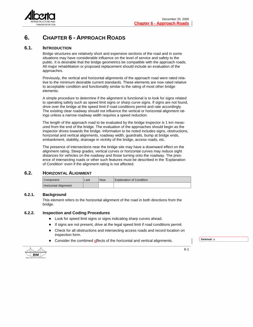
Girder Type: FC, VF, FM, LF Crack Rating Description
5 Narrow crack in chamfer between web and flange. May extend into deck underside or web. Generally found near girder end but may also extend to first diaphragm location.
1.
4 Medium or wide crack in chamfer between web and flange. May extend into deck underside or web. Generally found near girder end but may also extend to first diaphragm location.
5 Hairline or narrow longitudinal crack in bottom half of web at girder end. 2.
4 Medium or wide longitudinal crack in bottom half of web at girder end. 5 Hairline or narrow longitudinal crack at underside of girder leg at girder end.
3. 4 Medium or wide longitudinal crack at underside of girder leg at girder end.
4. 5 Diagonal crack in the transition and wide web section of the web at girder end (reduce by 1 if extending into top flange or extending into narrow web section).
Table 7.5 - Exception List - Girder Type: FC, VF, FM, LF
Girder Type: Deck Bulb Tee Girders Crack Rating Description
1. 5 Diagonal crack in the transition and wide web section of the web at girder end (reduce by 1 if extending into top flange or extending into narrow web section).
Table 7.6 - Exception List - Girder Type: Deck Bulb Tee Girder
Girder Type: VS, SM, SC, RD, RM, PM, VM Crack Rating Description
1. 5
Diagonal crack on bottom of girder, not longer than 0.5 m. Crack length must be continuous and not intermittent or staggered. Crack lengths to be measured from the face of the pier cap or abutment seat and along the length of the crack (with no signs of corrosion staining).
3
Diagonal crack on bottom of girder, not longer than 0.5 m. Crack length must be continuous and not intermittent or staggered. Crack lengths to be measured from the face of the pier cap or abutment seat and along the length of the crack (with signs of corrosion staining).
2. 5 Longitudinal crack on girder underside. 3. 5 Longitudinal crack at lower curb fascia.
4. 5 Crack in poured connection at fascia over piers (RM, RD, SMC, SCC, SCM, SLC).
Table 7.7 - Exception List- Girder Type: VS, SM, SC, RD, RM, PM, VM

December 20, 2005 Chapter 8 - Substructure
8-4
BIMBridge Inspection and Maintenance
8.5.2. Inspection and Coding Procedures ● Look for good contact and adequate bearing areas between the girders or bridge
bearings and the bridge seat, caps, or corbels. The same applies to the interface between the caps/corbels and the piles. Note any gaps or uneven bearing surfaces.
● Check for evidence of loose connections or corrosion of drift pins. ● Check for rotation or displacement of caps or corbels. This usually indicates sub-
structure movement, caused by high lateral pressure of the soil. ● Check bearing seats/caps for dampness or ponding and debris accumulation
caused by open or leaking joints. ● Check all timber caps and corbels for decay, especially in areas susceptible to
moisture accumulation and constant wetting and drying. Typical areas are the interface between the girders or piles and the cap, around dowels or bolt holes, and at the ends. Coring may be required to determine if rot is present in the caps and corbels. All core holes used for inspection must be filled with suitable plugs. Coring of timber is generally carried out with a Level 2 inspection.
● Examine all timber caps and corbels for splitting, crushing, bulging or cracking. Check for evidence of crushing at the interfaces between girders or piles and the caps or corbels.
● Check concrete seats/caps for cracks, spalls, corrosion of reinforcement, and disintegration of the concrete.
● Check steel caps for corrosion and cracks at welds, especially at connections. Look for bending and deformation of the web and flanges.
● Check keeper plates on the bearing seat. ● Note if file tag is missing. ● Record or confirm the type of bearing seat, cap, or corbel. ● Record or confirm the width and depth of the caps and corbels using nominal
dimensions (i.e. 305x305 mm or 305x356 mm). ● Record the total number of individual pieces of abutment caps, subcaps and
corbels in structure (both abutments). ● Record the total number of individual pieces of pier caps, subcaps and corbels in
structure (all piers).
8.5.3. Rating Guidelines ● Timber caps/corbels with vertical or horizontal cracks extending through the full
depth of the caps, rate 4 or less. ● Timber caps/corbels with signs of crushing, rate 2 or less. ● Caps/corbels with signs of bulging, rate 3 or less. ● Caps with a girder bearing length less than 100 mm, rate 4 or less. ● Caps with a girder bearing length less than 75 mm, rate 3 or less.
Formatted: Bullets and Numbering

December 20, 2005 Chapter 8 - Substructure
8-18
BIMBridge Inspection and Maintenance
8.15. GENERAL RATING The substructure general rating is governed by:
● ratings for structural load carrying elements ● bearing seat or cap rating ● pile rating ● backwall rating of 2 or less ● stability rating
The element ratings for both abutment and pier must be taken into account when assigning the overall substructure general rating.
Deleted: severe
Deleted: problems

December 20, 2005
Chapter 9 – Channel - Bridges
BIMBridge Inspection and Maintenance
9-3
9.2.3. Rating Guidelines ● If the abutments and piers are aligned with the flow, rate 8 or 9. ● If flow impinges on the piers and abutments at an angle and causes local scour,
drift accumulation, etc., rate 4 or less. ● If stream banks are unstable in the vicinity of the structure, rate 4 or less.
9.3. SLOPE PROTECTION Component Last Now Explanation of Condition
Slope Protection
(Type : )
9.3.1. Background This item rates the effectiveness of scour/erosion protection systems used at headslopes.
Scour/erosion usually occurs at the upstream end of abutments, and along the toe of headslopes and full-height abutments. Protection systems commonly used at stub or spill-through abutments are revetments of either concrete slabs, concrete blocks, con-crete sacks, heavy rock rip-rap, or gabions. At full-height abutments, the toe of the breastwall is sometimes protected with heavy rock rip-rap or gabions.
9.3.2. Inspection and Coding Procedures ● Check the headslope and the transition into the natural bank for signs of instabil-
ity, i.e. cracks, slumps, erosion, etc. ● Note possible cause of instability or scour/erosion such as channel misalignment,
drift accumulation, inadequate opening, etc. ● Check the protection system for signs of physical deterioration and displacement. ● If protection is required, but none exists, also rate under scour/erosion at abut-
ments (section 8.11 Scour / Erosion). Also, recommend a protection system under 'Maintenance Recommendations'.
● Note the type of the headslope protection on the BIM form.
9.3.3. Rating Guidelines ● If no protection exists, and none is required, rate 7 or more and indicate Type as
Natural. ● If no protection exists but is required, rate 4 or less and indicate Type as None. ● If the protection system is insufficient and/or needs repair, rate 4 or less.
Deleted: 5

December 20, 2005
Chapter 9 – Channel - Bridges
BIMBridge Inspection and Maintenance
9-7
Instream Trees Large weighted trees with attached roots and branches, sunk into a deep pool or run.
Rock Weirs Small rock dams lower in the centre than at the sides to direct the flow towards the cen-tre of the channel, often constructed as a V pointing upstream and sometimes used with a fish pool immediately downstream.
Fish Pools Pools excavated in the bottom of a stream, 0.5 m to 2.0 m deep, sometimes lined with rock or with larger rocks placed in the bottom.
Fish compensation measures are not rated but the inspector is to provide comments as required.
9.7. GENERAL RATING The channel general rating is governed by:
● channel alignment rating ● bank stability rating of 4 or less ● slope protection rating ● adequacy of opening rating
Deleted: problems
Deleted: inadequate

December 20, 2005
Chapter 11 - Bridge Inspection / Maintenance Summary
BIMBridge Inspection and Maintenance
11-3
● Maintenance recommendations can include any of the following: replacement, repair, rehabilitation, assessment, Level 2 inspections, reduced inspection cycle or monitoring.
● The recommendation to “monitor” should be used sparingly. It should be used for items that are measurable and where comparison of changes can be made with clear and readily identifiable reference marks.
● Timing of bridge maintenance recommendation should generally follow the time-lines indicated below depending on the element rating and also take into consid-eration the routine inspection cycle for the bridge: 4 low priority 3 (structural element) medium priority, repairs and maintenance completed
before the next inspection (six months to three years) e.g. timber cap rated 3, fix within a year
3 (non-structural) repairs may be delayed if defect not impacting life and operation of the structure e.g. bridgerail coating rated 3
2 high priority, repairs and maintenance completed within six months 1 immediate action
● If there are no maintenance recommendations the inspector records N in the ‘Maintenance Required’ field. If there are maintenance recommendations, record Y.
11.2.3. Estimating Quantities Where practical and applicable, the inspector is to estimate the material quantities required for recommended repairs and maintenance. These estimated quantities are to be recorded on a separate sheet of paper and submitted with the inspection report.
Example: ● 5 – 305mm x 75mm x 3.0m long timber stripdeck planks
11.2.4. Recommending Level 2 Inspections Level 2 inspections are detailed inspections requiring specialized equipment and/or expertise. These inspections gather specific information, measurements and observa-tions not captured on the routine Level 1 inspections. Further information on Level 2 inspections may be found in the Level 2 BIM Inspection Manual. Recommendations for Level 2 inspections can be made by inspectors during the routine Level 1 inspection. The Department will review the recommendations and make arrangements for the Level 2 inspection if it is required.
Municipalities should not undertake any site preparation measures until the Bridge Manager has been contacted and agrees a Level 2 inspection is required.
11.2.5. Recommending Additional Inspections after 2 Consecutive N Ratings If a structural load carrying element has a rating of N for two consecutive inspections and the element may govern the Substructure or Superstructure General rating, an additional inspection of the element should be recommended. This inspection could be
Formatted: Bullets and Numbering
Formatted: Body Text

December 20, 2005 Chapter 11 - Bridge Inspection / Maintenance Summary
11-4
BIMBridge Inspection and Maintenance
either a Level 1 inspection in a different season or a Level 2 inspection with the necessary equipment mobilized to access the element in question.
The decision to proceed with an additional inspection will be made by the Bridge Manager or his designate based upon the element in question, age and condition of the structure and other factors. No planning or preparation for an additional inspection should be done until the Bridge Manager has reviewed the recommendation and is in agreement with it.
11.2.6. Timber Coring Level 2 timber coring inspections are recommended when there are suspicions of rot in timber elements. Particular attention should be given to the critical structural load carry-ing elements such as timber caps, piles and stringers. Coring is generally conducted on timber load carrying substructure elements where rot is suspected or the element is 25 years or older. Subsequent coring may be required based on the results of the initial coring.
11.3. ESTIMATED REPLACEMENT YEAR The estimated replacement year is the inspector's subjective estimate, at the time of the inspection, of when the structure will need to be replaced assuming normal/routine maintenance is carried out but without including the effects of possible major rehabilita-tion. This estimate should be based on factors such as structural condition, horizontal and vertical alignments, traffic volumes, age, etc.
Life expectancy tables for each standard bridge type are provided below to help with this estimation.
The values in the table are averages only and the inspector must apply judgment based on the actual condition of the structure. The table is separated into three categories for low, average and high life expectancy.
LIFE EXPECTANCY TABLE FOR STANDARD BRIDGES
LIFE EXPECTANCY (YEARS) TYPE
Low Average High
Untreated Timber (UT) 10 15 20 Treated Timber (TT) 35 40 45 Prestressed – Composite (SCC,SMC,SCM,SLC) 55 60 70 Prestressed (SC, SM, VS)** 40 45 60* Precast (HC, VH, HH, PG, GR, MM, PES)** 30 35 50 Precast (PA) & Other (PX) 25 30 45 * Use maximum of 50 years for timber substructure ** Add five years if overlaid with concrete
Formatted: Bullets and Numbering

December 20, 2005 Chapter 12 - Bridge Structural Condition and Sufficiency Ratings
12-8
BIMBridge Inspection and Maintenance
Step 1 Structural Condition (A): For Superstructure: A1 = 2.5 x (6 - 1) = 12.5% For Substructure: A2 = 1.875 x (5 - 1) = 7.5%
Thus, A = 12.5 + 7.5 = 20%
Step 2 Loading (B): For Design Loading: B1B = 0.333 x ((3.6 x 14) - 30) = 6.8%
Step 3 Operational & Safety (C): For Approach Roads: C1 = 1.5 x (4 - 1) = 4.5% For Bridge Width: C2A = 28.571 x ((7.6 / 9) - 0.65) = 5.6%
(governs) C2B = 10% since BW is greater than 7.3 m
For Vertical Clearance: C3 = 8% For Channel Adequacy: C4 = 1.25 x (6 - 1) = 6.3% For Traffic Safety Features: Posting Info = 0 (missing sign)
Approach Guardrails = 0 (do not meet std.) Bridgerails = 0 for timber rails Deck Rideability = 1 Thus, C = 4.5 + 5.6 + 8 + 6.3 + 1= 25.4%
Step 4 Traffic Reduction Factor (D): For AADT: D1A = (((100 - 25)/ 36) exp. 0.28) - 0.5 = 0.7%
D1B = 0.10 x (100 - (20+6.8+ 25.4)) = 4.8% For Detour Length: D2A = (100 x 8) / 3000= 0.3%
D2B = 0.2 (100 - (20+6.8+25.4)) = 9.6% Thus, D = 0.7 + 0.3 = 1%
SUFFICIENCY RATING IS = (20 +6.8 +25.4 - 1) = 51.2 %
Deleted: 20
Deleted: 14
Deleted: 1 (
Deleted: )
Deleted: 2
Deleted: 6
Deleted: 14
Deleted: 30.9
Deleted: 3.5
Deleted: 14
Deleted: 30.9
Deleted: 7.0
Deleted: 14
Deleted: 6
Deleted: 9.4

December 20, 2005 Chapter 13 - Culverts
13-8
BIMBridge Inspection and Maintenance
On an embankment with a berm, the steepest slope either above or below the berm is recorded. The two slopes should not be averaged. Embankments with berms or varying sideslopes must also be described in the ‘Explanation of Condition’.
Figure 13.3 - Roadway Embankment Sideslopes Over Culverts
13.4.3.2. Inspection and Coding Procedures ● Look for cracks or other evidence of instability in the roadway, sideslopes, and
end transitions. ● Look for signs of erosion such as gullying along the sideslopes. ● Check toe of sideslopes and end transitions for erosion/scour. ● Estimate and note the slope of the sideslopes (horizontal: vertical). The steeper
of the upstream or downstream sideslope should be noted.
13.4.3.3. Rating Guidelines ● Embankments with erosion problems, rate 4 or less. ● Embankments with stability problems that may affect the roadway surface, rate 3
or less.
13.4.4. Height of Cover The height of cover is defined as the average vertical distance between the top of the roadway (centerline) and the top (crown) of the culvert and is measured to the nearest 0.1 m.
13.4.5. Guardrail The ends of culverts, including those with retaining walls, can be hazardous to traffic. As such, guardrails or other types of railing are generally installed along the outside edge of the shoulders to create a safer driving environment. If guardrails exist along both shoul-ders, the inspector should record Y in the field provided. Additional notes are required if guardrails are installed along one shoulder only, or if they are too short or ineffective.
13.4.6. Approach Road General Rating The approach road general rating is governed by:
● horizontal alignment rating ● vertical alignment rating ● embankment rating of 3 or less Deleted: safety or stability concerns with
the

December 20, 2005 Chapter 13 - Culverts
13-10
BIMBridge Inspection and Maintenance
13.5.2. Headwall Upstream End OR Downstream End
Culvert Component Last Now Explanation of Condition
Headwall
13.5.2.1. Background Headwalls are generally constructed from concrete, timber, or steel. They are located over the crown of the pipe and are usually attached to the barrel. They are used on cul-verts for aesthetics, strengthening of the ends, and resisting buoyancy forces. In some situations they may be used as retaining walls.
13.5.2.2. Inspection and Coding Procedures ● Look for signs of movement, tilting, and loose connections. ● Check concrete for cracks and deterioration. ● Check the stream-side face of concrete headwall for evidence of stains. ● Check timber for decay, missing planks, and gaps between planks. ● Check steel components for rust. ● Determine the effectiveness of the design as related to functionality and
aesthetics. ● The rating should reflect the condition of the headwall, including all connections,
as well as any defects that may reduce its aesthetics.
13.5.2.3. Rating Guidelines ● Defects which affect the functionality of the headwall, rate 4 or less.
13.5.3. Collar Upstream End OR Downstream End
Culvert Component Last Now Explanation of Condition
Collar
13.5.3.1. Background Collars are generally constructed from concrete and are used around beveled slopes of flexible culverts, starting at the cutoff wall and ending at the headwall. In some cases, they are used independently of the headwalls and the cutoff wall. Their advantages include aesthetics, shortening the bevel, resisting buoyancy forces, and increasing the hydraulic efficiency of the culvert.
13.5.3.2. Inspection and Coding Procedures ● Check the effectiveness of the collar. ● Look for cracks, deterioration, and loose connections to the barrel or bevel. ● Rate the condition of the collar and its ability to function as originally designed.
Deleted: / Concrete Slope Protection
Deleted: /Concrete Slope Protection
Deleted: Concrete slope protection is used in combination with collars to provide the added advantages of scour/erosion protection and minimizing piping through the structural fill.
Deleted: /concrete slope protection
Deleted: Look for evidence of piping and scour/erosion.
Deleted: /concrete slope protection,

December 20, 2005
Chapter 13 - Culverts
BIMBridge Inspection and Maintenance
13-15
13.5.6.3. Rating Guidelines ● If no bevel exists, rate X (square end). ● If the defects or deformation do not affect the culvert aesthetics or performance,
rate 6 or less (e.g. a bevel end with no fill along the sides, but no heaving or con-dition or functionality problems).
● If corrosion is severe enough to affect the strength and functionality of the bevel, rate 4 or less. Otherwise the coating condition should not affect the functionality and rating of the bevel.
13.5.7. Scour Protection Upstream End OR Downstream End
Upstream End OR Downstream End
Culvert Component Last Now Explanation of Condition
Scour Protection
(Type : )
(Avg. Rock Size (mm) : )
13.5.7.1. Background One of the design considerations for culverts located on streams with erodable beds and banks, is to ensure that the velocities and eddies at the ends are adequately handled with an erosion protection system. In many cases, heavy rock rip-rap of sufficient size and proper gradation is used. Often, the designer specifies the minimum requirements to provide some assurance against extensive damage during major floods and expects the bridge inspector will determine if more protection is required. Inadequate protection, especially on the downstream end, may result in undermining of the culvert, develop-ment of large and deep scour holes which may induce slumps and slides, and the for-mation of sandbars which may reduce the hydraulic efficiency of the structure.
In some cases, concrete scour protection is used in combination with concrete collars. The concrete scour protection provides scour protection for the embankment and has the added advantage of minimizing piping through the structural fill.
13.5.7.2. Inspection and Coding Procedures ● Note or verify the type of scour protection. ● Note or verify the average size of the rock protection and look for signs of rock
displacement. ● Check the thickness of the rock layer as well as the gradation of the rocks, when
possible. ● Check the rocks to determine if they have started to disintegrate. ● On grade separation culverts or stock passes, rate the quality and effectiveness
of the rocks along the cut slopes. ● Check the effectiveness of the concrete scour protection. Look for evidence of
piping and scour/erosion. Formatted: Bullets and Numbering

December 20, 2005 Chapter 13 - Culverts
13-16
BIMBridge Inspection and Maintenance
● Rate the condition of the concrete scour protection and its ability to function as originally designed.
13.5.7.3. Rating Guidelines ● As a general rule, the scour protection rating should not be greater than the
scour rating if it is less than 5. In this situation, a scour problem has been identi-fied and rated below acceptable condition and functionality. It follows that the scour protection is not adequately functioning and therefore cannot be rated higher than the scour rating.
● If the protected areas are smaller than required and/or the gradation and quality of the rocks are inadequate, rate the scour protection 4 or less. If there are no signs of scour or erosion, the scour rating could be higher than 4 but the scour protection rating should remain at 4 or less.
● Concrete scour protection that has excessive settlement or is undermined, rate 4 or less.
● If no scour protection exists and none is required, rate the protection 7 or more and note the type as Natural.
● If no scour protection exists but is required, rate the protection 4 or less and note the type as None and make recommendation for scour protection.
● If there are no signs of scour/erosion that may affect the culvert, and no evidence of displacement or deterioration, rate 7 or more.
● If a cattlepass also carries water flow, the inspector is to rate scour and scour protection. Otherwise, these elements are to be rated X for cattlepasses.
13.5.8. Scour / Erosion Upstream End OR Downstream End
Culvert Component Last Now Explanation of Condition
Scour/Erosion
13.5.8.1. Background Scour/erosion refers to the removal of material from the streambed and/or bank by the erosive action of the stream flow. It is classified as:
a) general scour which is a uniform lowering of the original streambed b) local scour which occurs at specific locations such as along culvert footings and
wingwalls Scour at culvert outlets is a common condition, and if undetected may undermine the culvert, initiate slumps or slides, adversely affect the culvert hydraulics, and impede fish passage. The failure and/or inefficient operation of many bridge size culverts located on a stream with erodable streambed and banks can be traced to scour/erosion.
Formatted: Bullets and Numbering
Deleted: 5
Deleted: 5

December 20, 2005
Chapter 13 - Culverts
BIMBridge Inspection and Maintenance
13-17
13.5.8.2. Inspection and Coding Procedures ● Check the areas in vicinity of culvert footings, wingwalls, collars, cutoffs, and the
ends of the protection system. ● Look for scour holes within rock rip-rap protection systems. ● Look for signs of undermining of transition slopes and stream bank. ● Check areas where the stream flow impinges on the banks or protection system. ● The rating should include the adverse effects of scour/erosion on the culvert,
embankment material, streambed, and banks.
13.5.8.3. Rating Guidelines ● If the culvert and the embankment material are not affected, rate 5 or more. ● If there is any form of scour or erosion that may affect the culvert, rate 4 or less.
13.5.9. Beavers Upstream End OR Downstream End
Culvert Component Last Now Explanation of Condition
Beavers (Y/N)
13.5.9.1. Background Beaver dams around culverts are almost impossible to eliminate completely unless the beaver population is reduced or removed. Problems caused by beaver dams include flooding, washouts, and culvert blockage.
13.5.9.2. Inspection and Coding Procedures ● Note Y if beaver dam exists at a location in or near the culvert that would affect
the integrity and operation of the culvert and describe location and extent of problem in ‘Explanation of Condition’.
13.5.10. Upstream / Downstream Ends General Rating The culvert end general ratings are governed by:
● headwall rating ● collar rating ● wingwall rating ● cutoff wall rating ● bevel end rating ● scour protection rating ● if all elements are rated X, then provide a general rating based on the overall
condition of the culvert end. Formatted: Bullets and Numbering
Deleted: inadequate
Deleted: <#>scour and erosion problems

December 20, 2005
Chapter 13 - Culverts
BIMBridge Inspection and Maintenance
13-19
13.6.2. Inaccessible Barrel Sections When the barrel section of a culvert is inaccessible, the barrel elements are rated N unless an obvious defect is noted.. Previous comments are retained for information by putting brackets around the comments or parts thereof that cannot be verified and adding the date the comment originated. The inspector should note in the ‘Explanation of Condition’ the culvert was viewed from the ends (if possible) and the condition as viewed from the ends should be recorded (i.e. general shape and condition – good/adequate/fair/poor).
For culverts where the barrel section is inaccessible and the critical elements are rated N the general rating may be rated N or the previous general rating may be carried over. If a critical barrel element was previously rated 4 or less, resulting in a general rating of 4 or less, the previous general rating must be carried over. A comment must be provided in the ‘Explanation of Condition’ indicating this. On the other hand, if the previous critical element ratings resulted in a general rating of 5 or greater, the general rating should be N. This is done because if the culvert barrel general rating is N, the system defaults to a general rating of 5 for the calculation of the Structural Condition Rating. Additionally, if the general rating on the previous inspection was rated N and the general rating on the current inspection is rated N, the inspector must review the previous inspections for when the culvert barrel was last accessible for inspection and confirm that the N rating has been carried forward correctly.
If the barrel is inaccessible but an obvious defect is visible from the end, the element is rated accordingly and another inspection should be scheduled during low flow conditions to thoroughly inspect the element. For example, the roof may show signs of distress and the previous rating indicates it was adequate. The roof should be down rated with com-ments in ‘Explanation of Condition’.
13.6.3. Special Features Bridge Culvert Barrel
Culvert Component Last Now Explanation of Condition
Special Features
Special Features
(Type : )
Special Features
(Type : )
13.6.3.1. Background Special features on culverts are listed under the barrel section of the inspection form. These are culvert elements that are unique to a particular culvert and cannot be rated under any other element. It is necessary to record the type of special feature and provide a condition rating for the element. These elements may be temporary or permanent features of the culvert.
Deleted: if the inspector cannot see enough to adequately assign a rating.

December 20, 2005
Chapter 13 - Culverts
BIMBridge Inspection and Maintenance
13-29
Figure 13.10 - Properly Lapped Seam
Figure 13.11 – Improperly Lapped Seam with Longitudinal Cracks
Deleted: -
Deleted: Cracked
Deleted: Seam

December 20, 2005 Chapter 13 - Culverts
13-30
BIMBridge Inspection and Maintenance
13.6.10. Coating Bridge Culvert Barrel
Culvert Component Last Now Explanation of Condition
Coating
Corrosion By Soil (Y/N)
Corrosion by Water (Y/N)
13.6.10.1. Background This item is applicable to steel culverts only and rates the condition of the zinc or alumi-num coating and any additional coating that may exist on the culvert. Photos of varying degrees of culvert corrosion are shown in Figure 13.12 to Figure 13.14.
A zinc or aluminum coating is applied to steel culverts to control and prevent corrosion which generally results in reduced load carrying capacity, infiltration of backfill material, and an unattractive appearance. Corrosion is initiated after the protective coating is removed, damaged, or perforated. The zinc coating sets up galvanic cells by sacrificing itself to protect the steel. Corrosion in culverts occurs from both the outside (soil side) and inside (water side). It is difficult to recognize corrosion on the outside until extensive damage in the form of rust perforations can be detected from the inside. Corrosion caused by water usually begins on the invert plates, which are susceptible to abrasion.
13.6.10.2. Inspection and Coding Procedures ● Check barrel for fabrication and installation defects such as blisters, foreign inclu-
sions, uncovered surfaces, and damage to the protective coating. ● Check barrel for evidence of pitting and perforations. ● Check all abrasion areas, bolts, and areas around bolt holes for signs of
corrosion. ● Rust stains through bolt holes and rust perforations in the top arc are signs of
outside (soil) corrosion. ● Note Y if corrosion is from soil and/or water.
13.6.10.3. Rating Guidelines ● Extensive corrosion and pitting in roof and/or sidewalls, rate 4. ● Isolated perforations in floor, rate 4. ● Isolated perforations in roof and/or sidewalls, rate 3. ● Extensive perforations in floor, rate 3. ● Extensive perforations in roof and/or sidewalls, rate 2. ● Severe perforations in floor, rate 2. ● Severe perforations in roof and/or sidewalls, rate 1.
Formatted: Bullets and Numbering
Formatted: Bullets and Numbering
Formatted: Bullets and Numbering
Deleted: i
Deleted: e
Deleted: s

December 20, 2005
Chapter 13 - Culverts
BIMBridge Inspection and Maintenance
13-33
fish depends on many factors such as flow velocity, obstructions, etc. that change at different times. The inspector should rate what he sees at the time of inspection. A rating is required even if the stream is dry at the time of inspection. The inspector should note his logic for the rating in ‘Explanation of Condition’.
Fish baffles are used in culverts that are located on fish bearing streams and when the velocities in the culvert may impede fish passage. In general, the velocities in the culvert are higher than those in the natural stream. The fish baffles are used to reduce the velo-cities by increasing the culvert roughness, to provide rest areas for the fish, and in the case of weir-type baffles they provide a minimum depth of flow during low flow situa-tions. The types of baffles used are:
a) spoilers which may consist of precast concrete blocks attached to the invert b) large boulders which may be attached to the invert if they can be displaced dur-
ing peak floods c) weirs which are located perpendicular or skewed to the flow
13.6.12.2. Inspection and Coding Procedures ● Record the type of baffles on the BIM form. ● Check concrete baffles and their fasteners for deterioration and damage. ● Check baffles consisting of large boulders for signs of disintegration, displace-
ment, and loose fasteners.
13.6.12.3. Rating Guidelines ● Regardless of whether the stream is flowing or dry, culverts that appear
adequately sized and are in line with or below streambed, rate 5 or better. ● Undersized culverts or those with the upstream or downstream end above
streambed, rate 4 or less (see Figure 13.16). ● Culverts used as underpasses and stockpasses, rate X. ● If a cattlepass also carries water flow, the inspector is to rate fish passage.
Otherwise, this is to be rated X.
Formatted: Bullets and Numbering

December 20, 2005
Chapter 13 - Culverts
BIMBridge Inspection and Maintenance
13-35
bottom of the culvert. However, silt material may build up to an extent that it adversely affects the flow of water and possibly the passage of fish. Under high flow conditions, the accumulated material may reduce the flow area of the culvert and create backwater conditions upstream of the culvert. Under low flow conditions, the accumulated material may completely block the flow of water. Answer the inventory question Y only if the silt is adversely affecting the flow of water.
Drift Since culverts generally restrict the opening of the stream, the accumulation of drift is often a problem at culverts. Drift reduces the capacity of the culvert and can create backwater conditions upstream. In high water conditions drift can completely block the flow of a culvert causing flooding upstream. Answer the inventory question Y if drift exists at culvert and note location and extend in ‘Explanation of Condition’.
13.6.13.2. Inspection and Coding Procedures ● Check for reduction in size of the opening. Look for debris accumulation, siltation,
stream migration, and repair measures within the culvert. ● Check upstream and downstream sides of the culvert for high water marks. ● Look for unusual scour at the upstream and downstream ends that may indicate
the barrel is undersized. ● Look for new river engineering works in the vicinity of the culvert which may indi-
cate there is a problem with the barrel’s ability to pass required discharge.
13.6.13.3. Rating Guidelines ● An adequate opening, rate 5 or more. ● If the culvert opening has blockage of 50% or more due to restrictions of the bar-
rel opening, rate 3 or less. In ‘Explanation of Condition’ note the type of blockage (e.g. icing, silting, drift, etc.).
● If a cattlepass also carries water flow, the inspector is to rate waterway ade-quacy. Otherwise, these elements are to be rated X.
13.6.14. Barrel - General Rating The general rating of the culvert barrel is perhaps the most important rating the inspector has to provide for culverts. It reflects the current overall structural condition of the barrel relative to the new condition of a barrel that is free of deficiencies or defects. In some cases a single item such as seam failure may strongly influence this rating.
The culvert barrel general rating is governed by:
● ratings for structural load carrying elements ● roof rating ● sidewall rating ● circumferential seam rating of 2 or less ● longitudinal seam rating ● corrosion rating of 2 or less
Deleted: severe
Deleted: problems
Deleted: extensive
Deleted: and pitting problems

December 20, 2005
Chapter 13 - Culverts
BIMBridge Inspection and Maintenance
13-37
RTG COMMENTARY SHAPE LONGITUNDINAL SEAM CORROSION INFILTRATION ABRASION
9 New condition
8 Almost new con-dition. No repairs required in fore-seeable future
No visible signs of defects, distortion, or deformation.
No cracks or defects in seams.
No corrosion. No infiltration. No abrasion.
7 Good condition. No action required.
Horizontal and vertical dimensional changes are within 5% of the design dimensions.
No cracks or defects in seams.
No corrosion. No infiltration. No abrasion.
6 Generally good condition.
Horizontal and vertical dimensional changes within 5% of design dimensions.
No cracks or defects in seams.
Minor superfi-cial rust but no pitting.
No infiltration. No abrasion.
5 Adequate. No loss in structural strength.
Horizontal and vertical dimensional changes within 7% of the design dimensions.
No cracks in longitudinal seams, no buckled cor-rugations in sidewall or roof corrugations.
Some superfi-cial rust but no pitting.
No infiltration. Abrasion of floor, coating worn off.
4 Low priority for repair.
Horizontal and vertical dimensional changes are within 10% of the design dimensions.
Minor cracks in a single longitudinal seam but can still transmit load.
Extensive cor-rosion and pit-ting in roof and/or sidewalls, isolated perforations in floor.
No infiltration but fill material is exposed.
Abrasion of floor, some section loss, isolated perfo-rations.
3 Reduced struc-tural strength. Need for replacement, repair, and/or signing.
Horizontal or vertical dimensional changes are within 10% to 15% of the design dimen-sions.
Less than 100 mm of steel left between cracked bolt holes along the same longitudinal seam.
Isolated perfo-rations in roof and/or sidewall, extensive per-forations in floor.
Minor infiltration of backfill through defects.
Extensive perforations in floor.
2 High priority for replacement, repair, and/or signing. Requires contin-ued observation.
Horizontal or vertical dimensional changes exceeding 15% of the design dimensions. Extreme flattening of roof, inward movement of sidewalls, reverse curvature.
Less than 50 mm of steel left between cracked bolt holes along the same longitudinal seam, 2 or more seams with defects in the same barrel section.
Extensive per-forations in roof and/or sidewall, severe perfora-tions in floor.
Void behind culvert from loss of material due to infiltration.
Severe perfo-rations in floor.
1 Immediate action. Danger of collapse.
Reverse curvature in flat horizontal ellipse or round culvert under low fill. Any evidence of impending collapse.
2 or more longitudinal seams with severe cracks in the same bar-rel section.
Severe perfo-rations in roof and/or sidewall.
Major loss of backfill material due to infiltra-tion.
Continuous perforation due to abra-sion.
N Barrel cannot be accessed for proper inspection.
Table 13.3 - Rating Guide for Flexible Culvert
December 20, 2005
Chapter 13 - Culverts
BIMBridge Inspection and Maintenance
13-43
Rock Weirs Small rock dams lower in the centre than at the sides to direct the flow towards the cen-tre of the channel, often constructed as a V pointing upstream, and sometimes used with a fish pool immediately downstream.
Fish Pools Pools excavated in the bottom of a stream, 0.5 m to 2.0 m deep, sometimes lined with rock and sometimes with larger rocks placed in the bottom
Fish compensation measures are not rated but the inspector is to provide comments as required.
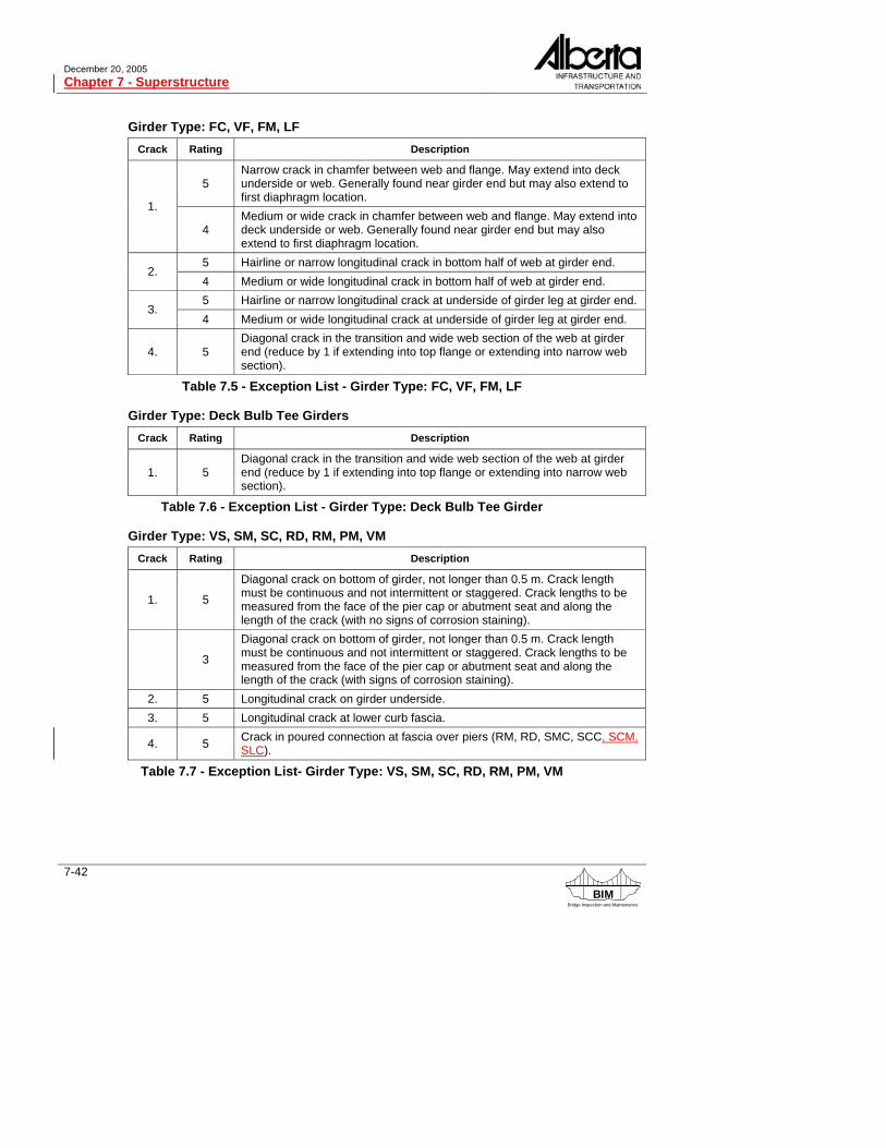
13.7.8. Culvert Channel General Rating The culvert channel general rating is governed by:
● channel alignment rating ● bank stability rating of 4 or less ● significant accumulations of drift
13.8. CULVERT GRADE SEPARATION SECTION This section replaces the channel section of the culvert form when the culvert is used as a grade separation. The culvert may be a vehicular, pedestrian or railway grade separa-tion or a cattle or wildlife underpass. Culverts are not commonly used for a grade sepa-ration of major roadways. However, they are often used for local access roads to farms, golf courses, etc. and for cattle and wildlife underpasses. They are also used for pedes-trian underpasses.
13.8.1. Road Alignment Structure Usage
Component Last Now Explanation of Condition
Grade Separation
Road Alignment
Information for rating road alignment for grade separations is covered in section 10.2 except for culvert surface roughness in the vicinity of the crossing which is considered under Roadway Surface. For railway, pedestrian and animal underpasses rate road alignment X.
Deleted: problems