Embed Size (px)
Citation preview

Chapter 1 Checklist Report by SerialVT0010NEP
EQUIPMENT/SYSTEM
Airflow indication/alarm system: Analog.
PMS: MIP 4361/002, MIP 4361/003, and MIP 4361/051.Technical Manuals: -NAVSEA Technical Manual SE168-AC-MMO-010/R1 (NSN 0910-LP-105-2467).Other: -SCD 74628 "Approved Installation Fielding Plan for Surface Ships," [formerly MACHALT No. 593-59006 (ECP
Analog
11. APPLICABLE INSPECTION PROCEDURES
3. PURPOSE
5. SUBSYSTEM 6. INSPECTORS REQUIREMENTS
4. REFERENCES
8 DESCRIPTION OF INSPECTION 9. PREREQUISITES
12. LOGISTICS / FUNDING 13. SECURITY CLEAR
14. SUPPORT SERVICES 15. SHIP CLASSES
7. UNDERWAY
2. MODEL / VERISON OF SYSTEM
16. CHECKLIST ITEMS 17. ADDITIONAL INSTRUCTIONS 18. NOTESSAT DEG UNSAT N/A
1. EQIUPMENT
Ship to provide inspector with Equipment Guide Lists (EGLs) of all airflow alarm panels and sensors.
2 each, two-way radios. ALL
Alarms for occupational health spaces that were inoperable will be considered a Priority 1 Safety deficiency with a maximum EOC score of 0.2. Alarms for Combat Systems equipment will be considered a Priority 2 deficiency with an EOC score up to 0.9. An
NSTM, SHIPS DRAWINGS
A. To conduct a compliance-focused inspection IAW SECNAVINST 5040.3A and U.S. Code, Title 10, S 7304. B. To implement process-focused inspection when feasible to strengthen the capability of the ship’s crew. C. Determine the ability of the ship’s crew
UNCLAS
The Ship is to provide two knowledgeable IC personnel with radios to demonstrate the air flow alarms. The ship should expect approximately 15 minutes per airflow alarm.
108 (i) SCD / MACHALT Accomplishment: References:-GSO 2004, 437d-Par. 3.1, 6.1, and 14.1 of SCD 74628 [formerly MACHALT No. 593-59006 (ECP No. 443)].-Par. 3.1, 6.1, and 14.1 of SCD 78209 [formerly MACHALT No. 593-59006 (ECP No. 443)].(1) All components of each MACHALT kit were installed
Wednesday, June 05, 2013 Page 1 of 2

EQUIPMENT/SYSTEM
107 (h) Sensor: References:-MIP 4361/002, A-9; MIP 4361/003; and MIP 4361-051.(1) Pinwheel sensor was correctly matched with airflow panel. [0-1K meter corresponds to Sensor No. 917-1-002 and Panel No. 62413-005. 0-5K corresponds to Sensor No. 4417-1-002 and Panel No
106 (g) Audible and Visual Alarm Labels: Identified at their respective locations by a label.
References:-GSO 2004, 602j.
105 (f) Remote/Extension Alarms. Remote/extension audible and visual alarms of the IC/SM alarm switchboard were activated in Central Control Station (CCS)/Damage Control Central (DCC), Enclosed Operating Station (EOS), etc. (as applicable).
References:-GSO 2004, 437d.NOTE: Location of remote/extension alarms only in an EOS are for ships not having a CCS/DCC.
104 (e) Airflow Alarm Operational Test per MIP 4361/002, A-10 OR 4361/051, A-7:
References:-MIP 4361/002, A-10 or MIP 4361/051, A-7.(1) Red alarm indicator lamp illuminates.(2) Local/Panel audible alarm sounds.(3) Remote audible and visual alarms sound (i.e., bell, strobe light, beacon, etc.).(4) Red flag drops.(5) Red and bla
103 (d) Warning Label Plate: References:-MIP 4361/002, A-10; MIP 4361/003, A-3; MIP 4361/051, A-7.-GSO 2004, 437d.(1) A warning label plate was installed in a prominent location on the exterior of the access door to the monitored compartment.(2) The warning label plate was in
102 (c) Airflow Indication/Alarm Set Point (ASP) Data Label Plate:
References:-MIP 4361/002, A-10 or 4361/051, A-7.(1) A label plate was installed on or in close proximity to the airflow control panel.(2) The following information was included on the data label plate: Monitored Compartment [noun name]/Circuit Numbe
101 (b) Airflow Indication/Alarm Panel Location: Panel was located external to the monitored compartment and adjacent to the access.
References: -GSO 2004, 437d.NOTE: Locating the panel in CCS/DCC, vice adjacent to the access, is not "fail safe." Personnel cannot easily verify airflow before entry into potentially hazardous atmospheres during periods when alarms are not signalling b
100. (a) Installation: The following spaces had required audible and visual exhaust ventilation airflow alarm systems:Alcohol Storerooms; Paint Mixing and Issue Rooms; Flammable Liquid Issue and Storerooms; Ship's Store Flammable Material Storerooms; H
References: -GSO 2004, 437d.-NSTM 510, 510-6.1.15; 510-7.1.12.NOTE: Supply ventilation airflow alarm systems installed in radar array rooms, combat information centers, and other electronics rooms are not for protection of personnel, but for protectio
Wednesday, June 05, 2013 Page 2 of 2

Chapter 1 Checklist Report by SerialVT0011NEP
EQUIPMENT/SYSTEM
Airflow indication/alarm system: Digital.
PMS: MIP 4361/002, MIP 4361/003, and MIP 4361/051.Technical Manuals: -NAVSEA Technical Manual T9491-XX-MMC-010 for Dynalec Model No. 62413-100.-NAVSEA Technical Manual S9491-AN-MMC-010/R1 (NSN 0910-LP-028-5240) for Henschel Model No. 20-300-1.NAVSEA
Dynalec Model No. 62413-100; Centron; Henschel Model No. 20-300-1.
Digital (DYNALEC, CENTRON, or HENSCHEL).
11. APPLICABLE INSPECTION PROCEDURES
3. PURPOSE
5. SUBSYSTEM 6. INSPECTORS REQUIREMENTS
4. REFERENCES
8 DESCRIPTION OF INSPECTION 9. PREREQUISITES
12. LOGISTICS / FUNDING 13. SECURITY CLEAR
14. SUPPORT SERVICES 15. SHIP CLASSES
7. UNDERWAY
2. MODEL / VERISON OF SYSTEM
16. CHECKLIST ITEMS 17. ADDITIONAL INSTRUCTIONS 18. NOTESSAT DEG UNSAT N/A
1. EQIUPMENT
Ship to provide inspector with Equipment Guide Lists (EGLs) of all airflow alarm panels and sensors.
2 each, two-way radios. ALL
Alarms for occupational health spaces that were inoperable will be considered a Priority 1 Safety deficiency with a maximum EOC score of 0.2. Alarms for Combat Systems equipment will be considered a Priority 2 deficiency with an EOC score up to 0.9. An
NSTM, SHIPS DRAWINGS
A. To conduct a compliance-focused inspection IAW SECNAVINST 5040.3A and U.S. Code, Title 10, S 7304. B. To implement process-focused inspection when feasible to strengthen the capability of the ship’s crew. C. Determine the ability of the ship’s crew
UNCLAS
The Ship is to provide two knowledgeable IC personnel with radios to demonstrate the air flow alarms. The ship should expect approximately 15 minutes per airflow alarm.
108 (i) SCD / MACHALT Accomplishment: References:-GSO 2004, 437d-Par. 3.1, 6.1, and 14.1 of SCD 74628 [formerly MACHALT No. 593-59006 (ECP No. 443)].-Par. 3.1, 6.1, and 14.1 of SCD 78209 [formerly MACHALT No. 593-59006 (ECP No. 443)].(1) All components of each MACHALT kit were installed
Wednesday, June 05, 2013 Page 1 of 2
EQUIPMENT/SYSTEM
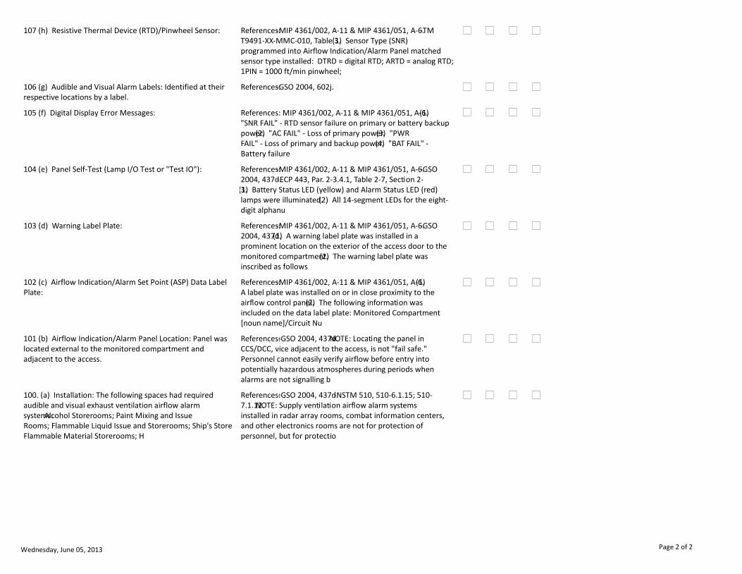
107 (h) Resistive Thermal Device (RTD)/Pinwheel Sensor: References:-MIP 4361/002, A-11 & MIP 4361/051, A-6.-TM T9491-XX-MMC-010, Table 3.(1) Sensor Type (SNR) programmed into Airflow Indication/Alarm Panel matched sensor type installed: DTRD = digital RTD; ARTD = analog RTD; 1PIN = 1000 ft/min pinwheel;
106 (g) Audible and Visual Alarm Labels: Identified at their respective locations by a label.
References:-GSO 2004, 602j.
105 (f) Digital Display Error Messages: References: MIP 4361/002, A-11 & MIP 4361/051, A-6.(1) "SNR FAIL" - RTD sensor failure on primary or battery backup power.(2) "AC FAIL" - Loss of primary power.(3) "PWR FAIL" - Loss of primary and backup power.(4) "BAT FAIL" - Battery failure
104 (e) Panel Self-Test (Lamp I/O Test or "Test IO"): References:-MIP 4361/002, A-11 & MIP 4361/051, A-6.-GSO 2004, 437d.-ECP 443, Par. 2-3.4.1, Table 2-7, Section 2-3.(1) Battery Status LED (yellow) and Alarm Status LED (red) lamps were illuminated.(2) All 14-segment LEDs for the eight-digit alphanu
103 (d) Warning Label Plate: References:-MIP 4361/002, A-11 & MIP 4361/051, A-6.-GSO 2004, 437d.(1) A warning label plate was installed in a prominent location on the exterior of the access door to the monitored compartment.(2) The warning label plate was inscribed as follows
102 (c) Airflow Indication/Alarm Set Point (ASP) Data Label Plate:
References:-MIP 4361/002, A-11 & MIP 4361/051, A-6.(1) A label plate was installed on or in close proximity to the airflow control panel.(2) The following information was included on the data label plate: Monitored Compartment [noun name]/Circuit Nu
101 (b) Airflow Indication/Alarm Panel Location: Panel was located external to the monitored compartment and adjacent to the access.
References: -GSO 2004, 437d.NOTE: Locating the panel in CCS/DCC, vice adjacent to the access, is not "fail safe." Personnel cannot easily verify airflow before entry into potentially hazardous atmospheres during periods when alarms are not signalling b
100. (a) Installation: The following spaces had required audible and visual exhaust ventilation airflow alarm systems:Alcohol Storerooms; Paint Mixing and Issue Rooms; Flammable Liquid Issue and Storerooms; Ship's Store Flammable Material Storerooms; H
References: -GSO 2004, 437d.-NSTM 510, 510-6.1.15; 510-7.1.12.NOTE: Supply ventilation airflow alarm systems installed in radar array rooms, combat information centers, and other electronics rooms are not for protection of personnel, but for protectio
Wednesday, June 05, 2013 Page 2 of 2

Chapter 1 Checklist Report by SerialVT0012NEP
EQUIPMENT/SYSTEM
Airflow indication/alarm system ILS Support.
PMS: MIP 4361/002, MIP 4361/003, and MIP 4361/051.Technical Manuals: -NAVSEA Technical Manual T9491-XX-MMC-010 for Dynalec Model No. 62413-100.-NAVSEA Technical Manual S9491-AN-MMC-010/R1 (NSN 0910-LP-028-5240) for Henschel Model No. 20-300-1.-NAVSEA
Analog or digital.
11. APPLICABLE INSPECTION PROCEDURES
3. PURPOSE
5. SUBSYSTEM 6. INSPECTORS REQUIREMENTS
4. REFERENCES
8 DESCRIPTION OF INSPECTION 9. PREREQUISITES
12. LOGISTICS / FUNDING 13. SECURITY CLEAR
14. SUPPORT SERVICES 15. SHIP CLASSES
7. UNDERWAY
2. MODEL / VERISON OF SYSTEM
16. CHECKLIST ITEMS 17. ADDITIONAL INSTRUCTIONS 18. NOTESSAT DEG UNSAT N/A
1. EQIUPMENT
ALL
Priority 2 deficiency.
NSTM, SHIPS DRAWINGS
A. To conduct a compliance-focused inspection IAW SECNAVINST 5040.3A and U.S. Code, Title 10, S 7304. B. To implement process-focused inspection when feasible to strengthen the capability of the ship’s crew. C. Determine the ability of the ship’s crew
UNCLAS
Conducted after physical inspection of airflow alarm systems.
102 (c) Equipment Guide Lists (EGLs): References: -MRC 4361/002; 4361/003, and 4361/051(1) An EGL was available for the airflow indication/alarm panels.(2) An EGL was available for the airflow alarm sensors.NOTE: Airflow indication/alarm panels and sensors require separate EGLs becau
101 (b) Preventive Maintenance System (PMS): References: -MRC 4361/002; 4361/003, and 4361/051(1) PMS was installed for MIP 4361. NOTE: The install will be verified by having the Ship's Force show the Sked Database to the INSURV inspector.(2) An Airflow Alarm System Log was filled out mont
100. (a) Technical Manuals: Technical manuals were onboard for each airflow alarm system installed.
References: -MRC 4361/002; 4361/003, and 4361/051
Wednesday, June 05, 2013 Page 1 of 1

Chapter 1 Checklist Report by SerialVT0020NEP
EQUIPMENT/SYSTEM
Fan Room.
Other:-NAVSEA S9AA0-AB-GOS-010/GSO "General Specifications for Overhaul of Surface Ships (GSO 2004)", Sections 070, 075, 507, & 512.-NSTM 505.-NSTM 510 "HVAC Systems for Surface Ships".
11. APPLICABLE INSPECTION PROCEDURES
3. PURPOSE
5. SUBSYSTEM 6. INSPECTORS REQUIREMENTS
4. REFERENCES
8 DESCRIPTION OF INSPECTION 9. PREREQUISITES
12. LOGISTICS / FUNDING 13. SECURITY CLEAR
14. SUPPORT SERVICES 15. SHIP CLASSES
7. UNDERWAY
2. MODEL / VERISON OF SYSTEM
16. CHECKLIST ITEMS 17. ADDITIONAL INSTRUCTIONS 18. NOTESSAT DEG UNSAT N/A
1. EQIUPMENT
None. ALL
NSTM, SHIPS DRAWINGS
A. To conduct a compliance-focused inspection IAW SECNAVINST 5040.3A and U.S. Code, Title 10, S 7304. B. To implement process-focused inspection when feasible to strengthen the capability of the ship’s crew. C. Determine the ability of the ship’s crew
UNCLAS
This event will require 2 to 3 days to complete on most ships. The Ship is to provide an escort.
116 (q) Grounding straps were not missing, painted, or physically damaged.
Reference: 300-2.2.1.2 of NSTM 300R8.NOTE: Ground straps are not required when metal enclosing cases or frames are in contact with one another and the metal structure of the ship. Ground straps are required if fan motors have rubber expansion joints an
103 (d) Deck was dry.
104 (e) There was no gear adrift and the space was not used for storage or an office.
References:-NSTM 510, 510-7.2.1.Scoring: Stowage of combustible liquids, combustible solids (e.g., paper, cardboard, and wood) and/or flammable materials in the space is a Priority 1 Safety deficiency.
105 (f) All filter cover fasteners were in place.
Wednesday, June 05, 2013 Page 1 of 2

EQUIPMENT/SYSTEM
106 (g) Pipe lagging was in place and dry.
107 (h) Cooling coils were clean.
108 (i) Manual damper handle was operational and not tied open.
109 (j) Differential pressure gages were intact and operational.
110 (k) Drain pans were clean and free of corrosion.
111 (l) Ducting was intact, not damaged, and free of corrosion.
112 (m) Expansion joints were not painted or physically damaged.
113 (n) Fan nose cones were in place.
102 (c) Bullseye was posted.
115 (p) Foundation frame/brackets were in good condition and free of corrosion.
101 (b) CCOL was posted.
117 (r) Vent inspection covers were in place.
118 (s) Electrical fans were not installed or wired backwards.
119 (t) Protective screens were in place and not damaged. Scoring: Missing or loose protective screens allowing access to rotating fan parts is a Priority 1 Safety deficiency.
120 (u) All protective screen fasteners were in place.
121 (v) Resilient mounts were not painted.
122 (w) Lagging was properly stenciled.
123 (x) Pipe and duct stenciling was in place and correct.
124 (y) Electrical connecting box fasteners were in place. Scoring: Unsheathed electrical wiring, missing junction/connecting box covers, or exposed electrical conductors is a Priority 1 Safety deficiency.
125 (z) Thermostats were operational.
126 (aa) Drain pans were not clogged and were free of corrosion.
100. (a) Light fixtures were operational. Scoring: If all light fixtures in a fan room are inoperable, it is a Priority 2 Safety deficiency.
114 (o) Proper filters were installed in appropriate fans.
Wednesday, June 05, 2013 Page 2 of 2

Chapter 1 Checklist Report by SerialVT0021NEP
EQUIPMENT/SYSTEM
Fan Coil Units (FCUs) inside Fan Rooms.
(a) S6230-CC-MMA-010.(b) 0948-LP-119-1010.(c) S6435-L4-OMI-010.(d) S9514-D2-MMC-010.(e) S9514-FQ-MMC-010.(f) S9514-A5-MMA-010.(g) S9514-EA-MMA-010.(h) MIP 6641/005, MRC A1JW (M-3).(i) MIP 6641/005, MRC W31G (Q-2/S-2).(j) MIL-PRF-24775A.
11. APPLICABLE INSPECTION PROCEDURES
3. PURPOSE
5. SUBSYSTEM 6. INSPECTORS REQUIREMENTS
4. REFERENCES
8 DESCRIPTION OF INSPECTION 9. PREREQUISITES
12. LOGISTICS / FUNDING 13. SECURITY CLEAR
14. SUPPORT SERVICES 15. SHIP CLASSES
7. UNDERWAY
2. MODEL / VERISON OF SYSTEM
16. CHECKLIST ITEMS 17. ADDITIONAL INSTRUCTIONS 18. NOTESSAT DEG UNSAT N/A
1. EQIUPMENT
None. ALL
NSTM, SHIPS DRAWINGS
A. To conduct a compliance-focused inspection IAW SECNAVINST 5040.3A and U.S. Code, Title 10, S 7304. B. To implement process-focused inspection when feasible to strengthen the capability of the ship’s crew. C. Determine the ability of the ship’s crew
UNCLAS
This event is part of the Fan Rooms event. Fan Rooms will require 2 to 3 days to complete on most ships. The Ship is to provide an escort.
113 (n) Grounding strap was provided and mounted properly from unit to hull and not corroded.
References:-S9514-D2-MMC-010.-S9514-FQ-MMC-010.-MIL-PRF-24775A.Scoring: Missing, loose, or unattached grounding straps is a Priority 1 Safety deficiency.
112 (m) FCU drain was not sweating. Drain was secured to FCU properly and terminated properly. Condensate was not leaking out of FCU panels.
Drain pipe section of applicable ship specification.
111 (l) Thermostat was set to design setpoint (72 degrees F). There were no airflow blockages or dirt/debris buildup.
References:-S6230-CC-MMA-010.-S9514-D2-MMC-010.-S9514-FQ-MMC-010.
Wednesday, June 05, 2013 Page 1 of 2

EQUIPMENT/SYSTEM
110 (k) Air filter was present and not loaded with dirt. There were no blockages to airflow. Metal air filters were free of corrosion and the inlet side was coated with oil. Disposable filters may be installed instead of metal filters; however, air fil
References:-S6230-CC-MMA-010.-S9514-D2-MMC-010.-S9514-FQ-MMC-010.-S9514-A5-MMA-010.-S9514-EA-MMA-010.-MIP 6641/005, MRC W31G (Q-2/S-2).
109 (j) Chilled water piping was complete, dry, not damaged, and free of deterioration.
Pipe section of applicable ship specification.
108 (i) FCU chilled water solenoid valve operated properly. The manual override should align for automatic thermostat control as follows: - 1/2” and 3/4” ASCO valve shaft should be pressed in and turned fully counter-clockwise.- Larger ASCO valves, sta
References:-0948-LP-119-1010.-S6435-L4-OMI-010.
107 (h) When FCU was energized, the air filter gage (applicable to FCUs with gage provided; see applicable ship specification HVAC section to see if gage is required) indicated above zero but below the red region (i.e., dirty filter condition). There wer
References:-MIP 6641/005, MRC A1JW (M-3).
106 (g) When FCU was energized, there was no unusual loud operation, vibration, or mechanical noise.
105 (f) When FCU was energized, none of the F3, F4, or F5 fuse lamps were illuminated (these illuminate when the fuses serving the heater element are blown).
References:-S6230-CC-MMA-010.-S9514-D2-MMC-010.-S9514-FQ-MMC-010.-S9514-A5-MMA-010.-S9514-EA-MMA-010.
104 (e) When FCU was energized, neither the F1 nor the F2 fuse lamps were illuminated (these illuminate when the fuses serving the low voltage control circuit are blown).
References:-S6230-CC-MMA-010.-S9514-D2-MMC-010.-S9514-FQ-MMC-010.-S9514-A5-MMA-010.-S9514-EA-MMA-010.
103 (d) Stop and Start pushbuttons (LVP Types) or On/Off switch (LVR Types) functioned properly. When energized, fan should turn on and "ON" indicator lamp illuminates. When secured, fan should turn off and "ON" indicator lamp does not illuminate.
References:-S6230-CC-MMA-010.-S9514-D2-MMC-010.-S9514-FQ-MMC-010.-S9514-A5-MMA-010.-S9514-EA-MMA-010.
102 (c) FCU housing was intact and not missing hardware, and was free of damage and corrosion.
References:-MIL-PRF-24775A.
101 (b) FCU intake and outlet was free of damage and airflow obstruction.
100. (a) FCU mounting hardware was intact and in good operating condition.
Wednesday, June 05, 2013 Page 2 of 2

Chapter 1 Checklist Report by SerialVT0022NEP
EQUIPMENT/SYSTEM
Fan Coil Assemblies (FCAs) inside Fan Rooms
(a) 0948-LP-119-1010.(b) S6435-L4-OMI-010.(c) MIP 6641/005, MRC A1JW (M-3).(d) MIP 6641/005, MRC W31G (Q-2/S-2).(e) S6230-A8-MMA-010.(f) S6230-BB-MMO-010.(g) S9514-DR-MMA-010.(h) S9514-DS-MMA-010.(i) S9514-DV-MMC-010.(j) MIL-PRF-23798D.
11. APPLICABLE INSPECTION PROCEDURES
3. PURPOSE
5. SUBSYSTEM 6. INSPECTORS REQUIREMENTS
4. REFERENCES
8 DESCRIPTION OF INSPECTION 9. PREREQUISITES
12. LOGISTICS / FUNDING 13. SECURITY CLEAR
14. SUPPORT SERVICES 15. SHIP CLASSES
7. UNDERWAY
2. MODEL / VERISON OF SYSTEM
16. CHECKLIST ITEMS 17. ADDITIONAL INSTRUCTIONS 18. NOTESSAT DEG UNSAT N/A
1. EQIUPMENT
None. ALL
NSTM, SHIPS DRAWINGS
A. To conduct a compliance-focused inspection IAW SECNAVINST 5040.3A and U.S. Code, Title 10, S 7304. B. To implement process-focused inspection when feasible to strengthen the capability of the ship’s crew. C. Determine the ability of the ship’s crew
UNCLAS
This event is part of the Fan Rooms event. Fan Rooms will require 2 to 3 days to complete on most ships. The Ship is to provide an escort.
109 (j) Grounding strap was provided and mounted properly from unit to hull and not corroded.
References:-S6230-A8-MMA-010.-S9514-DR-MMA-010.-S9514-DS-MMA-010.-S9514-DV-MMC-010.-MIL-PRF-23798D.Scoring: Missing, loose, or unattached grounding straps is a Priority 1 Safety deficiency.
108 (i) FCA drain was not sweating. Drain was secured to FCA properly and terminated properly. Condensate was not leaking out of FCA panels.
Drain pipe section of applicable ship specification.
Wednesday, June 05, 2013 Page 1 of 2

EQUIPMENT/SYSTEM
107 (h) Air filter was present and not loaded with dirt. There were no blockages to airflow. Metal air filters were free of corrosion and the inlet side was coated with oil. Disposable filters may be installed instead of metal filters; however, air fil
References:-MIP 6641/005, MRC W31G (Q-2/S-2).-S6230-A8-MMA-010.-S6230-BB-MMO-010.-S9514-DR-MMA-010.-S9514-DS-MMA-010.-S9514-DV-MMC-010.
106 (g) Chilled water piping was complete, dry, not damaged, and free of deterioration.
Pipe section of applicable ship specification.
105 (f) FCA chilled water solenoid valve operated properly. The manual override should align for automatic thermostat control as follows: - 1/2” and 3/4” ASCO valve shaft should be pressed in and turned fully counter-clockwise.- Larger ASCO valves, sta
References:-0948-LP-119-1010.-S6435-L4-OMI-010.
104 (e) When FCA was energized, the air filter differential pressure gage (applicable to FCAs with gage provided; see applicable ship specification HVAC section to see if gage is required) indicated above zero but below the red region (i.e., dirty filter
References:-MIP 6641/005, MRC A1JW (M-3).-S6230-A8-MMA-010.-S6230-BB-MMO-010.-S9514-DR-MMA-010.-S9514-DS-MMA-010.-S9514-DV-MMC-010.
103 (d) When FCU was energized, there was no unusual loud operation, vibration, or mechanical noise.
102 (c) FCA housing was intact and not missing hardware, and was free of damage and corrosion.
References:-MIL-PRF-23798D.
101 (b) FCA intake and outlet was free of damage and airflow obstruction.
100. (a) FCA mounting hardware was intact and in good operating condition.
Wednesday, June 05, 2013 Page 2 of 2
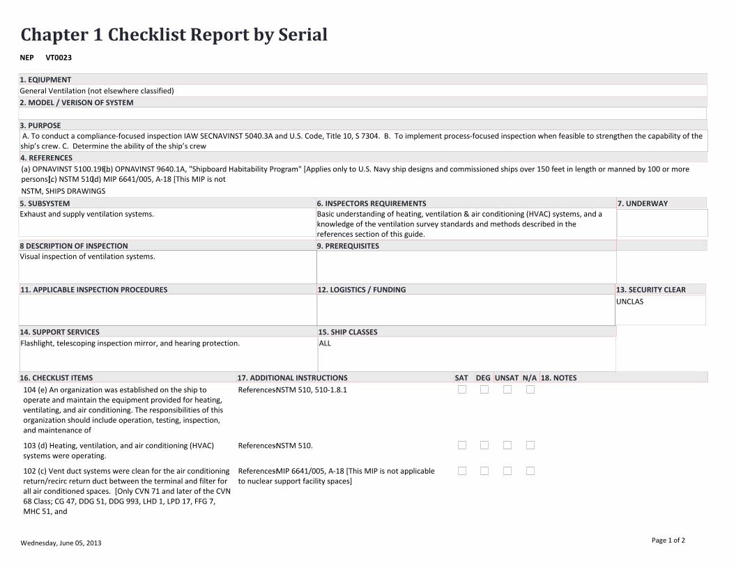
Chapter 1 Checklist Report by SerialVT0023NEP
EQUIPMENT/SYSTEM
General Ventilation (not elsewhere classified)
(a) OPNAVINST 5100.19E.(b) OPNAVINST 9640.1A, "Shipboard Habitability Program" [Applies only to U.S. Navy ship designs and commissioned ships over 150 feet in length or manned by 100 or more persons].(c) NSTM 510.(d) MIP 6641/005, A-18 [This MIP is not
Exhaust and supply ventilation systems.
11. APPLICABLE INSPECTION PROCEDURES
3. PURPOSE
5. SUBSYSTEM 6. INSPECTORS REQUIREMENTS
4. REFERENCES
8 DESCRIPTION OF INSPECTION 9. PREREQUISITES
12. LOGISTICS / FUNDING 13. SECURITY CLEAR
14. SUPPORT SERVICES 15. SHIP CLASSES
7. UNDERWAY
2. MODEL / VERISON OF SYSTEM
16. CHECKLIST ITEMS 17. ADDITIONAL INSTRUCTIONS 18. NOTESSAT DEG UNSAT N/A
1. EQIUPMENT
Basic understanding of heating, ventilation & air conditioning (HVAC) systems, and a knowledge of the ventilation survey standards and methods described in the references section of this guide.
Visual inspection of ventilation systems.
Flashlight, telescoping inspection mirror, and hearing protection. ALL
NSTM, SHIPS DRAWINGS
A. To conduct a compliance-focused inspection IAW SECNAVINST 5040.3A and U.S. Code, Title 10, S 7304. B. To implement process-focused inspection when feasible to strengthen the capability of the ship’s crew. C. Determine the ability of the ship’s crew
UNCLAS
104 (e) An organization was established on the ship to operate and maintain the equipment provided for heating, ventilating, and air conditioning. The responsibilities of this organization should include operation, testing, inspection, and maintenance of
References:-NSTM 510, 510-1.8.1
103 (d) Heating, ventilation, and air conditioning (HVAC) systems were operating.
References:-NSTM 510.
102 (c) Vent duct systems were clean for the air conditioning return/recirc return duct between the terminal and filter for all air conditioned spaces. [Only CVN 71 and later of the CVN 68 Class; CG 47, DDG 51, DDG 993, LHD 1, LPD 17, FFG 7, MHC 51, and
References:-MIP 6641/005, A-18 [This MIP is not applicable to nuclear support facility spaces]
Wednesday, June 05, 2013 Page 1 of 2
EQUIPMENT/SYSTEM
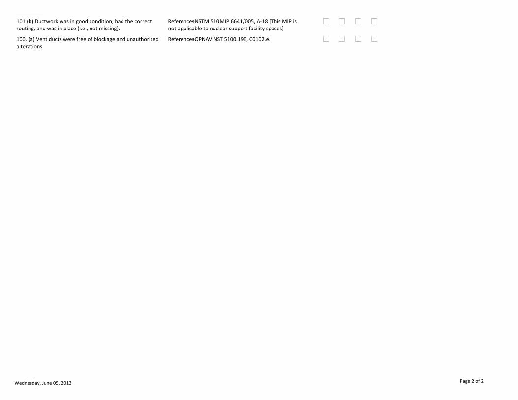
101 (b) Ductwork was in good condition, had the correct routing, and was in place (i.e., not missing).
References:-NSTM 510.-MIP 6641/005, A-18 [This MIP is not applicable to nuclear support facility spaces]
100. (a) Vent ducts were free of blockage and unauthorized alterations.
References:-OPNAVINST 5100.19E, C0102.e.
Wednesday, June 05, 2013 Page 2 of 2

Chapter 1 Checklist Report by SerialVT0030NEP
EQUIPMENT/SYSTEM
Sanitary Ventilation Systems (i.e., water closets, wash rooms, and showers).
(a) NAVSEA 0938-LP-018-0010 "HVAC Design Criteria Manual for Surface Ships of the U.S. Navy" (29 March 1991), Criteria Sheets 7A and 9D.(b) NAVSEA DWG NO: 802-5959327, "HVAC Design Criteria Manual," pp. 18-32 & 18-32A [DDG].(c) LHD Ship Specification, A
Exhaust ventilation terminals/ducts.
General Exhaust Ventilation (GEV).
11. APPLICABLE INSPECTION PROCEDURES
3. PURPOSE
5. SUBSYSTEM 6. INSPECTORS REQUIREMENTS
4. REFERENCES
8 DESCRIPTION OF INSPECTION 9. PREREQUISITES
12. LOGISTICS / FUNDING 13. SECURITY CLEAR
14. SUPPORT SERVICES 15. SHIP CLASSES
7. UNDERWAY
2. MODEL / VERISON OF SYSTEM
16. CHECKLIST ITEMS 17. ADDITIONAL INSTRUCTIONS 18. NOTESSAT DEG UNSAT N/A
1. EQIUPMENT
Basic understanding of heating, ventilation & air conditioning (HVAC) systems, a proficient use of ventilation survey equipment, and a knowledge of the ventilation survey standards and methods described in the references section of this guide.
Ensure all supply and exhaust ventilation systems for the space are operating. If a ship is outfitted with a Chemical Protective System (CPS), and that system is not always set during routine daily operations (e.g., CPS on DDGs is always set), then ensur
Design exhaust air volumes (in CFM) and/or design exhaust air rates of change for each space. This information can be found on a ship's Heating, Ventilation & Air Conditioning (HVAC) drawing, in a HVAC Design Criteria Manual, or in a Ship's Information B
Shoulder bag, flashlight, telescoping inspection mirror, hearing protection, rotating/swinging vane anemometer (4-inch diameter vane preferred) with an articulating wand (i.e., bendable up to 90 degrees), thermal (i.e., heated wire/element) anemometer wit
ALL
The percent of the design will be the EOC score for that space. However, a space with a percent of design at or below 10 percent will be considered as having a zero air volume (it can be possible that exhaust volumes at or below 10 percent are caused by
NSTM, SHIPS DRAWINGS
A. To conduct a compliance-focused inspection IAW SECNAVINST 5040.3A and U.S. Code, Title 10, S 7304. B. To implement process-focused inspection when feasible to strengthen the capability of the ship’s crew. C. Determine the ability of the ship’s crew
UNCLAS
This event will require two days to complete.
107 (h) Existing air conditioning systems were balanced so that the delivered quantity of air to each compartment was not less than 90 percent, nor more than 110 percent of design quantity.
References: Section 512L of NAVSEA S9AA0-AB-GOS-010/GSO "General Specifications for Overhaul of Surface Ships (GSO 2004)"NOTE: Applicable unless specified differently by applicable ship class specification. The "no more than 110 percent" criteria only
106 (g) New air conditioning systems were balanced so that the delivered quantity of air to each compartment was not less than 100 percent, nor more than 110 percent, of design quantity. [TRIALS ONLY]
References: Section 512L of NAVSEA S9AA0-AB-GOS-010/GSO "General Specifications for Overhaul of Surface Ships (GSO 2004)"NOTE: Applicable unless specified differently by applicable ship class specification. The "no more than 110 percent" criteria only
Wednesday, June 05, 2013 Page 1 of 2
EQUIPMENT/SYSTEM
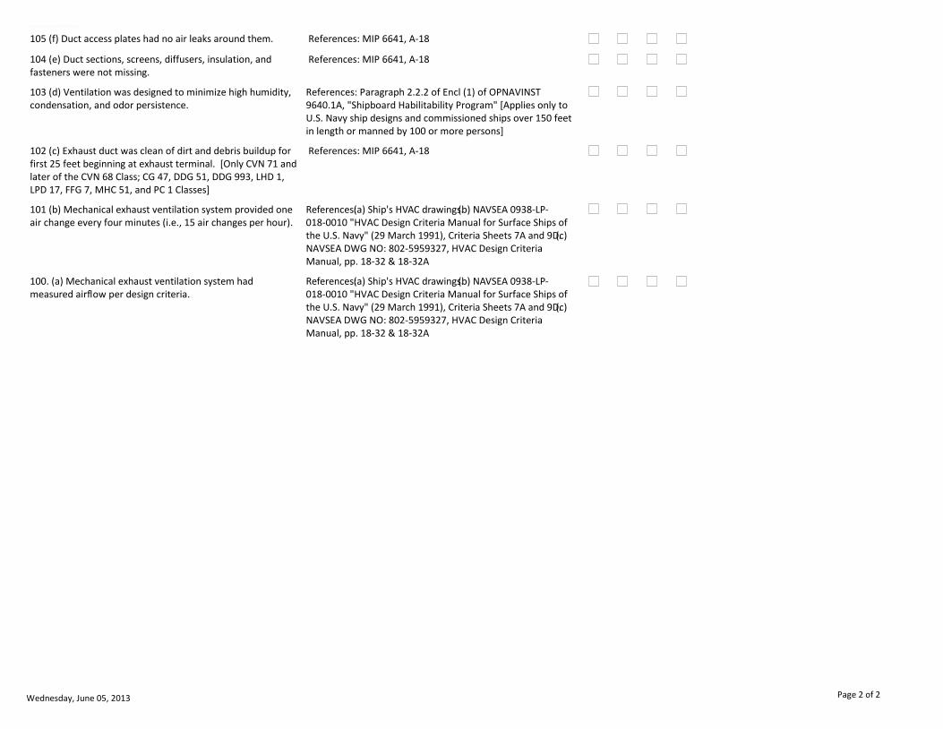
105 (f) Duct access plates had no air leaks around them. References: MIP 6641, A-18
104 (e) Duct sections, screens, diffusers, insulation, and fasteners were not missing.
References: MIP 6641, A-18
103 (d) Ventilation was designed to minimize high humidity, condensation, and odor persistence.
References: Paragraph 2.2.2 of Encl (1) of OPNAVINST 9640.1A, "Shipboard Habilitability Program" [Applies only to U.S. Navy ship designs and commissioned ships over 150 feet in length or manned by 100 or more persons]
102 (c) Exhaust duct was clean of dirt and debris buildup for first 25 feet beginning at exhaust terminal. [Only CVN 71 and later of the CVN 68 Class; CG 47, DDG 51, DDG 993, LHD 1, LPD 17, FFG 7, MHC 51, and PC 1 Classes]
References: MIP 6641, A-18
101 (b) Mechanical exhaust ventilation system provided one air change every four minutes (i.e., 15 air changes per hour).
References: (a) Ship's HVAC drawings.(b) NAVSEA 0938-LP-018-0010 "HVAC Design Criteria Manual for Surface Ships of the U.S. Navy" (29 March 1991), Criteria Sheets 7A and 9D.(c) NAVSEA DWG NO: 802-5959327, HVAC Design Criteria Manual, pp. 18-32 & 18-32A
100. (a) Mechanical exhaust ventilation system had measured airflow per design criteria.
References: (a) Ship's HVAC drawings.(b) NAVSEA 0938-LP-018-0010 "HVAC Design Criteria Manual for Surface Ships of the U.S. Navy" (29 March 1991), Criteria Sheets 7A and 9D.(c) NAVSEA DWG NO: 802-5959327, HVAC Design Criteria Manual, pp. 18-32 & 18-32A
Wednesday, June 05, 2013 Page 2 of 2

Chapter 1 Checklist Report by SerialVT0050NEP
EQUIPMENT/SYSTEM
Ventilation Plenum Preservation Inspection [CVN ONLY].
(a) OPNAVINST 5100.19E.(b) NACE International "Shipboard Corrosion Assessment Training".
11. APPLICABLE INSPECTION PROCEDURES
3. PURPOSE
5. SUBSYSTEM 6. INSPECTORS REQUIREMENTS
4. REFERENCES
8 DESCRIPTION OF INSPECTION 9. PREREQUISITES
12. LOGISTICS / FUNDING 13. SECURITY CLEAR
14. SUPPORT SERVICES 15. SHIP CLASSES
7. UNDERWAY
2. MODEL / VERISON OF SYSTEM
16. CHECKLIST ITEMS 17. ADDITIONAL INSTRUCTIONS 18. NOTESSAT DEG UNSAT N/A
1. EQIUPMENT
Inspection conducted on Wednesday in port. 10 spaces chosen by random from CCIMS database on Tuesday.
Ship to follow confined space entry procedures for each ventilation plenum.
Flashlight, inspection mirror, digital laser tape measure, and self-retracting tape measure.
CVN
Inspect spaces using NACE International shipboard corrosion assessment criteria.
NSTM, SHIPS DRAWINGS
A. To conduct a compliance-focused inspection IAW SECNAVINST 5040.3A and U.S. Code, Title 10, S 7304. B. To implement process-focused inspection when feasible to strengthen the capability of the ship’s crew. C. Determine the ability of the ship’s crew
UNCLAS
Inspect 10 ventilation plenums for preservation. Plenums are chosen at random from ship's CCIMS database.
100. (a) Ship-assigned CCIMS category for ventilation plenum was accurate.
Wednesday, June 05, 2013 Page 1 of 1
Chapter 1 Checklist Report by SerialVT0060NEP
EQUIPMENT/SYSTEM
Vehicle Stowage Area Ventilation [LHD CLASS ONLY].
(a) Ship's Heating, Ventilation & Air Conditioning (HVAC) drawings.(b) Ship-specific HVAC Design Criteria Manual.(c) Ship's Heating, Ventilation & Air Conditioning (HVAC) drawings.(d) NAVSEA "HVAC Design Criteria Manual" (LHD 5 thru 7), Design Criteria
Exhaust ventilation terminals/ducts.
General Exhaust Ventilation (GEV).
11. APPLICABLE INSPECTION PROCEDURES
3. PURPOSE
5. SUBSYSTEM 6. INSPECTORS REQUIREMENTS
4. REFERENCES
8 DESCRIPTION OF INSPECTION 9. PREREQUISITES
12. LOGISTICS / FUNDING 13. SECURITY CLEAR
14. SUPPORT SERVICES 15. SHIP CLASSES
7. UNDERWAY
2. MODEL / VERISON OF SYSTEM
16. CHECKLIST ITEMS 17. ADDITIONAL INSTRUCTIONS 18. NOTESSAT DEG UNSAT N/A
1. EQIUPMENT
Basic understanding of heating, ventilation & air conditioning (HVAC) systems, a proficient use of ventilation survey equipment, and a knowledge of the ventilation survey standards and methods described in the references section of this guide.
Ensure all supply and exhaust ventilation systems for the space are operating. If the ventilation fans have two speeds, then take air velocity measurements at both speeds. Close all access doors/hatches/scuttles to the space before taking air velocity m
Design exhaust air volumes (in CFM) for each space. This information can be found on a ship's Heating, Ventilation & Air Conditioning (HVAC) drawing, in a HVAC Design Criteria Manual, or in a Ship's Information Book.
Shoulder bag, flashlight, telescoping inspection mirror, hearing protection, rotating/swinging vane anemometer (4-inch diameter vane preferred) with an articulating wand (i.e., bendable up to 90 degrees), thermal (i.e., heated wire/element) anemometer wit
LHD 5 thru 7
A space with a percent of design at or below 10 percent will be considered as having a zero air volume (it can be possible that exhaust volumes at or below 10 percent are caused by an inoperative exhaust fan and supply air exiting through the exhaust term
NSTM, SHIPS DRAWINGS
A. To conduct a compliance-focused inspection IAW SECNAVINST 5040.3A and U.S. Code, Title 10, S 7304. B. To implement process-focused inspection when feasible to strengthen the capability of the ship’s crew. C. Determine the ability of the ship’s crew
UNCLAS
This system is part of INSURV Event No. VT0060. This entire event will require one to two days to complete.
102 (c) Connections were provided to exhaust system to accommodate flexible hoses used for exhaust of vehicle gaseous emissions. [LHD 5 thru 7]
References:(a) NAVSEA "HVAC Design Criteria Manual" (LHD 5 thru 7), Design Criteria No. 37.(b) NAVSEA S9AA0-AB-GOS-010/GSO "General Specifications for Overhaul of Surface Ships (GSO 2004)", Sections 512 and 575.
101 (b) Mechanical exhaust ventilation system fans provide a 2.75 minute rate of change (i.e., 21.8 air changes per hour). [LHD 5 thru 7]
References:(a) NAVSEA "HVAC Design Criteria Manual" (LHD 5 thru 7), Design Criteria No. 37.(b) NAVSEA S9AA0-AB-GOS-010/GSO "General Specifications for Overhaul of Surface Ships (GSO 2004)", Sections 512 and 575.
Wednesday, June 05, 2013 Page 1 of 2
EQUIPMENT/SYSTEM
100. (a) Mechanical supply ventilation system fans provide a 2.75 minute rate of change (i.e., 21.8 air changes per hour). [LHD 5 thru 7]
References:(a) NAVSEA "HVAC Design Criteria Manual" (LHD 5 thru 7), Design Criteria No. 37.(b) NAVSEA S9AA0-AB-GOS-010/GSO "General Specifications for Overhaul of Surface Ships (GSO 2004)", Sections 512 and 575.
Wednesday, June 05, 2013 Page 2 of 2
Chapter 1 Checklist Report by SerialVT0061NEP
EQUIPMENT/SYSTEM
Well Deck Area Ventilation [LHD CLASS ONLY].
(a) Ship's Heating, Ventilation & Air Conditioning (HVAC) drawings.(b) Ship-specific HVAC Design Criteria Manual.(c) Ship's Heating, Ventilation & Air Conditioning (HVAC) drawings.(d) NAVSEA "HVAC Design Criteria Manual" (LHD 5 thru 7), Design Criteria
Exhaust ventilation terminals/ducts.
General Exhaust Ventilation (GEV).
11. APPLICABLE INSPECTION PROCEDURES
3. PURPOSE
5. SUBSYSTEM 6. INSPECTORS REQUIREMENTS
4. REFERENCES
8 DESCRIPTION OF INSPECTION 9. PREREQUISITES
12. LOGISTICS / FUNDING 13. SECURITY CLEAR
14. SUPPORT SERVICES 15. SHIP CLASSES
7. UNDERWAY
2. MODEL / VERISON OF SYSTEM
16. CHECKLIST ITEMS 17. ADDITIONAL INSTRUCTIONS 18. NOTESSAT DEG UNSAT N/A
1. EQIUPMENT
Basic understanding of heating, ventilation & air conditioning (HVAC) systems, a proficient use of ventilation survey equipment, and a knowledge of the ventilation survey standards and methods described in the references section of this guide.
Ensure all supply and exhaust ventilation systems for the space are operating. If the ventilation fans have two speeds, then take air velocity measurements at both speeds. Close all access doors/hatches/scuttles to the space before taking air velocity m
Design exhaust air volumes (in CFM) for each space. This information can be found on a ship's Heating, Ventilation & Air Conditioning (HVAC) drawing, in a HVAC Design Criteria Manual, or in a Ship's Information Book.
Shoulder bag, flashlight, telescoping inspection mirror, hearing protection, rotating/swinging vane anemometer (4-inch diameter vane preferred) with an articulating wand (i.e., bendable up to 90 degrees), thermal (i.e., heated wire/element) anemometer wit
LHD 5 thru 7
A space with a percent of design at or below 10 percent will be considered as having a zero air volume (it can be possible that exhaust volumes at or below 10 percent are caused by an inoperative exhaust fan and supply air exiting through the exhaust term
NSTM, SHIPS DRAWINGS
A. To conduct a compliance-focused inspection IAW SECNAVINST 5040.3A and U.S. Code, Title 10, S 7304. B. To implement process-focused inspection when feasible to strengthen the capability of the ship’s crew. C. Determine the ability of the ship’s crew
UNCLAS
This system is part of INSURV Event No. VT0060. This entire event will require one to two days to complete.
101 (b) Mechanical exhaust ventilation system had measured airflow of 200,000 cfm. [LHD 5 thru 7]
References:(a) NAVSEA "HVAC Design Criteria Manual" (LHD 5 thru 7), Design Criteria No. 13.(b) NAVSEA S9AA0-AB-GOS-010/GSO "General Specifications for Overhaul of Surface Ships (GSO 2004)", Sections 512 and 575.
100. (a) Mechanical supply ventilation system had measured airflow of 200,000 cfm. [LHD 5 thru 7]
References:(a) NAVSEA "HVAC Design Criteria Manual" (LHD 5 thru 7), Design Criteria No. 13.(b) NAVSEA S9AA0-AB-GOS-010/GSO "General Specifications for Overhaul of Surface Ships (GSO 2004)", Sections 512 and 575.
Wednesday, June 05, 2013 Page 1 of 1
Chapter 1 Checklist Report by SerialVT0062NEP
EQUIPMENT/SYSTEM
Lower Vehicle Stowage Area Ventilation: Aft [LPD 17 CLASS ONLY].
(a) Ship's Heating, Ventilation & Air Conditioning (HVAC) drawings.(b) Ship-specific HVAC Design Criteria Manual.(c) Ship's Heating, Ventilation & Air Conditioning (HVAC) drawings.(d) NAVSEA "HVAC Design Criteria Manual" (LPD 17 Only), Design Criteria
Exhaust ventilation terminals/ducts.
General Exhaust Ventilation (GEV).
11. APPLICABLE INSPECTION PROCEDURES
3. PURPOSE
5. SUBSYSTEM 6. INSPECTORS REQUIREMENTS
4. REFERENCES
8 DESCRIPTION OF INSPECTION 9. PREREQUISITES
12. LOGISTICS / FUNDING 13. SECURITY CLEAR
14. SUPPORT SERVICES 15. SHIP CLASSES
7. UNDERWAY
2. MODEL / VERISON OF SYSTEM
16. CHECKLIST ITEMS 17. ADDITIONAL INSTRUCTIONS 18. NOTESSAT DEG UNSAT N/A
1. EQIUPMENT
Basic understanding of heating, ventilation & air conditioning (HVAC) systems, a proficient use of ventilation survey equipment, and a knowledge of the ventilation survey standards and methods described in the references section of this guide.
Ensure all supply and exhaust ventilation systems for the space are operating. If the ventilation fans have two speeds, then take air velocity measurements at both speeds. Close all access doors/hatches/scuttles to the space before taking air velocity m
Design exhaust air volumes (in CFM) for each space. This information can be found on a ship's Heating, Ventilation & Air Conditioning (HVAC) drawing, in a HVAC Design Criteria Manual, or in a Ship's Information Book.
Shoulder bag, flashlight, telescoping inspection mirror, hearing protection, rotating/swinging vane anemometer (4-inch diameter vane preferred) with an articulating wand (i.e., bendable up to 90 degrees), thermal (i.e., heated wire/element) anemometer wit
LPD 17
A space with a percent of design at or below 10 percent will be considered as having a zero air volume (it can be possible that exhaust volumes at or below 10 percent are caused by an inoperative exhaust fan and supply air exiting through the exhaust term
NSTM, SHIPS DRAWINGS
A. To conduct a compliance-focused inspection IAW SECNAVINST 5040.3A and U.S. Code, Title 10, S 7304. B. To implement process-focused inspection when feasible to strengthen the capability of the ship’s crew. C. Determine the ability of the ship’s crew
UNCLAS
This system is part of INSURV Event No. VT0060. This entire event will require one to two days to complete.
102 (c) There were two supply ventilation systems and two exhaust ventilation systems installed and both were operational. [LPD 17 and Follow]
References:(a) NAVSEA "HVAC Design Criteria Manual" (LPD 17 Only), Design Criteria No. 70.(b) NAVSEA "HVAC Design Criteria Manual" (LPD 18 Only), Design Criteria No. 70.(c) NAVSEA "HVAC Design Criteria Manual" (LPD 19 thru 22), Design Criteria No. 70.
Wednesday, June 05, 2013 Page 1 of 2

EQUIPMENT/SYSTEM
101 (b) Mechanical exhaust ventilation system fans provide a 2.75 minute rate of change (i.e., 21.8 air changes per hour). [LPD 17 and Follow]
References:(a) NAVSEA "HVAC Design Criteria Manual" (LPD 17 Only), Design Criteria No. 70.(b) NAVSEA "HVAC Design Criteria Manual" (LPD 18 Only), Design Criteria No. 70.(c) NAVSEA "HVAC Design Criteria Manual" (LPD 19 thru 22), Design Criteria No. 70.
100. (a) Mechanical supply ventilation system fans provide a 2.75 minute rate of change (i.e., 21.8 air changes per hour). [LPD 17 and Follow]
References:(a) NAVSEA "HVAC Design Criteria Manual" (LPD 17 Only), Design Criteria No. 70.(b) NAVSEA "HVAC Design Criteria Manual" (LPD 18 Only), Design Criteria No. 70.(c) NAVSEA "HVAC Design Criteria Manual" (LPD 19 thru 22), Design Criteria No. 70.
Wednesday, June 05, 2013 Page 2 of 2
Chapter 1 Checklist Report by SerialVT0063NEP
EQUIPMENT/SYSTEM
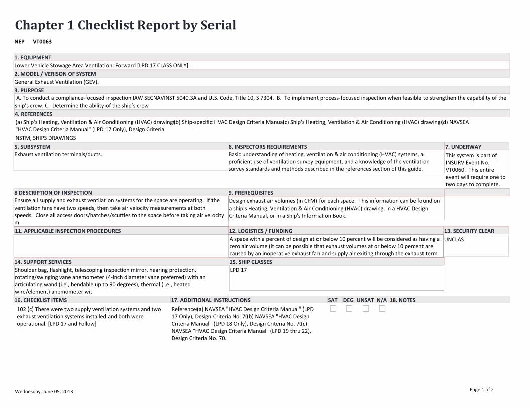
Lower Vehicle Stowage Area Ventilation: Forward [LPD 17 CLASS ONLY].
(a) Ship's Heating, Ventilation & Air Conditioning (HVAC) drawings.(b) Ship-specific HVAC Design Criteria Manual.(c) Ship's Heating, Ventilation & Air Conditioning (HVAC) drawings.(d) NAVSEA "HVAC Design Criteria Manual" (LPD 17 Only), Design Criteria
Exhaust ventilation terminals/ducts.
General Exhaust Ventilation (GEV).
11. APPLICABLE INSPECTION PROCEDURES
3. PURPOSE
5. SUBSYSTEM 6. INSPECTORS REQUIREMENTS
4. REFERENCES
8 DESCRIPTION OF INSPECTION 9. PREREQUISITES
12. LOGISTICS / FUNDING 13. SECURITY CLEAR
14. SUPPORT SERVICES 15. SHIP CLASSES
7. UNDERWAY
2. MODEL / VERISON OF SYSTEM
16. CHECKLIST ITEMS 17. ADDITIONAL INSTRUCTIONS 18. NOTESSAT DEG UNSAT N/A
1. EQIUPMENT
Basic understanding of heating, ventilation & air conditioning (HVAC) systems, a proficient use of ventilation survey equipment, and a knowledge of the ventilation survey standards and methods described in the references section of this guide.
Ensure all supply and exhaust ventilation systems for the space are operating. If the ventilation fans have two speeds, then take air velocity measurements at both speeds. Close all access doors/hatches/scuttles to the space before taking air velocity m
Design exhaust air volumes (in CFM) for each space. This information can be found on a ship's Heating, Ventilation & Air Conditioning (HVAC) drawing, in a HVAC Design Criteria Manual, or in a Ship's Information Book.
Shoulder bag, flashlight, telescoping inspection mirror, hearing protection, rotating/swinging vane anemometer (4-inch diameter vane preferred) with an articulating wand (i.e., bendable up to 90 degrees), thermal (i.e., heated wire/element) anemometer wit
LPD 17
A space with a percent of design at or below 10 percent will be considered as having a zero air volume (it can be possible that exhaust volumes at or below 10 percent are caused by an inoperative exhaust fan and supply air exiting through the exhaust term
NSTM, SHIPS DRAWINGS
A. To conduct a compliance-focused inspection IAW SECNAVINST 5040.3A and U.S. Code, Title 10, S 7304. B. To implement process-focused inspection when feasible to strengthen the capability of the ship’s crew. C. Determine the ability of the ship’s crew
UNCLAS
This system is part of INSURV Event No. VT0060. This entire event will require one to two days to complete.
102 (c) There were two supply ventilation systems and two exhaust ventilation systems installed and both were operational. [LPD 17 and Follow]
References:(a) NAVSEA "HVAC Design Criteria Manual" (LPD 17 Only), Design Criteria No. 70.(b) NAVSEA "HVAC Design Criteria Manual" (LPD 18 Only), Design Criteria No. 70.(c) NAVSEA "HVAC Design Criteria Manual" (LPD 19 thru 22), Design Criteria No. 70.
Wednesday, June 05, 2013 Page 1 of 2
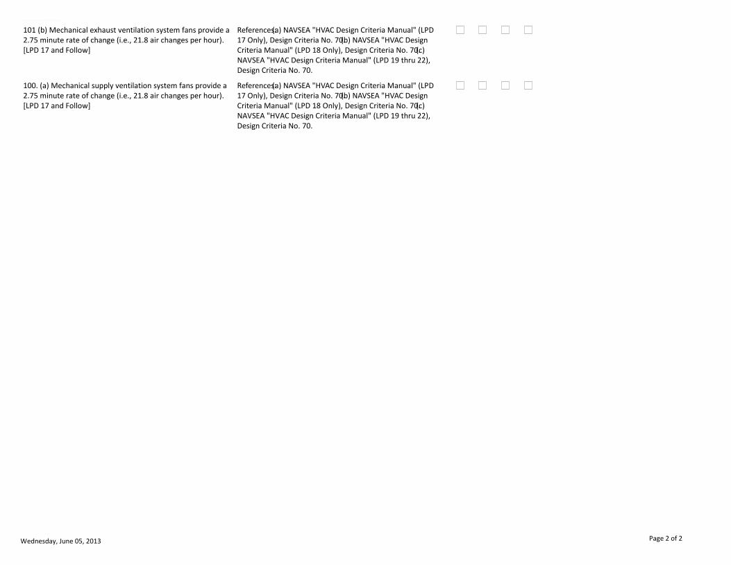
EQUIPMENT/SYSTEM
101 (b) Mechanical exhaust ventilation system fans provide a 2.75 minute rate of change (i.e., 21.8 air changes per hour). [LPD 17 and Follow]
References:(a) NAVSEA "HVAC Design Criteria Manual" (LPD 17 Only), Design Criteria No. 70.(b) NAVSEA "HVAC Design Criteria Manual" (LPD 18 Only), Design Criteria No. 70.(c) NAVSEA "HVAC Design Criteria Manual" (LPD 19 thru 22), Design Criteria No. 70.
100. (a) Mechanical supply ventilation system fans provide a 2.75 minute rate of change (i.e., 21.8 air changes per hour). [LPD 17 and Follow]
References:(a) NAVSEA "HVAC Design Criteria Manual" (LPD 17 Only), Design Criteria No. 70.(b) NAVSEA "HVAC Design Criteria Manual" (LPD 18 Only), Design Criteria No. 70.(c) NAVSEA "HVAC Design Criteria Manual" (LPD 19 thru 22), Design Criteria No. 70.
Wednesday, June 05, 2013 Page 2 of 2

Chapter 1 Checklist Report by SerialVT0064NEP
EQUIPMENT/SYSTEM
Well Deck, Main Vehicle Stowage Area, & Upper Vehicle Stowage Area Ventilation: Vehicle Emission Exhaust [LPD 17 CLASS ONLY].
(a) Ship's Heating, Ventilation & Air Conditioning (HVAC) drawings.(b) Ship-specific HVAC Design Criteria Manual.(c) Ship's Heating, Ventilation & Air Conditioning (HVAC) drawings.(d) NAVSEA "HVAC Design Criteria Manual" (LPD 17 Only), Design Criteria
Exhaust ventilation terminals/ducts.
Local Exhaust Ventilation (LEV).
11. APPLICABLE INSPECTION PROCEDURES
3. PURPOSE
5. SUBSYSTEM 6. INSPECTORS REQUIREMENTS
4. REFERENCES
8 DESCRIPTION OF INSPECTION 9. PREREQUISITES
12. LOGISTICS / FUNDING 13. SECURITY CLEAR
14. SUPPORT SERVICES 15. SHIP CLASSES
7. UNDERWAY
2. MODEL / VERISON OF SYSTEM
16. CHECKLIST ITEMS 17. ADDITIONAL INSTRUCTIONS 18. NOTESSAT DEG UNSAT N/A
1. EQIUPMENT
Basic understanding of heating, ventilation & air conditioning (HVAC) systems, a proficient use of ventilation survey equipment, and a knowledge of the ventilation survey standards and methods described in the references section of this guide.
Ensure all supply and exhaust ventilation systems for the space are operating. If the ventilation fans have two speeds, then take air velocity measurements at both speeds. Close all access doors/hatches/scuttles to the space before taking air velocity m
Design exhaust air volumes (in CFM) for each terminal/duct. This information can be found on a ship's Heating, Ventilation & Air Conditioning (HVAC) drawing, in a HVAC Design Criteria Manual, or in a Ship's Information Book.
Shoulder bag, flashlight, telescoping inspection mirror, hearing protection, rotating/swinging vane anemometer (4-inch diameter vane preferred) with an articulating wand (i.e., bendable up to 90 degrees), thermal (i.e., heated wire/element) anemometer wit
LPD 17
A space with a percent of design at or below 10 percent will be considered as having a zero air volume (it can be possible that exhaust volumes at or below 10 percent are caused by an inoperative exhaust fan and supply air exiting through the exhaust term
NSTM, SHIPS DRAWINGS
A. To conduct a compliance-focused inspection IAW SECNAVINST 5040.3A and U.S. Code, Title 10, S 7304. B. To implement process-focused inspection when feasible to strengthen the capability of the ship’s crew. C. Determine the ability of the ship’s crew
UNCLAS
This system is part of INSURV Event No. VT0060. This entire event will require one to two days to complete.
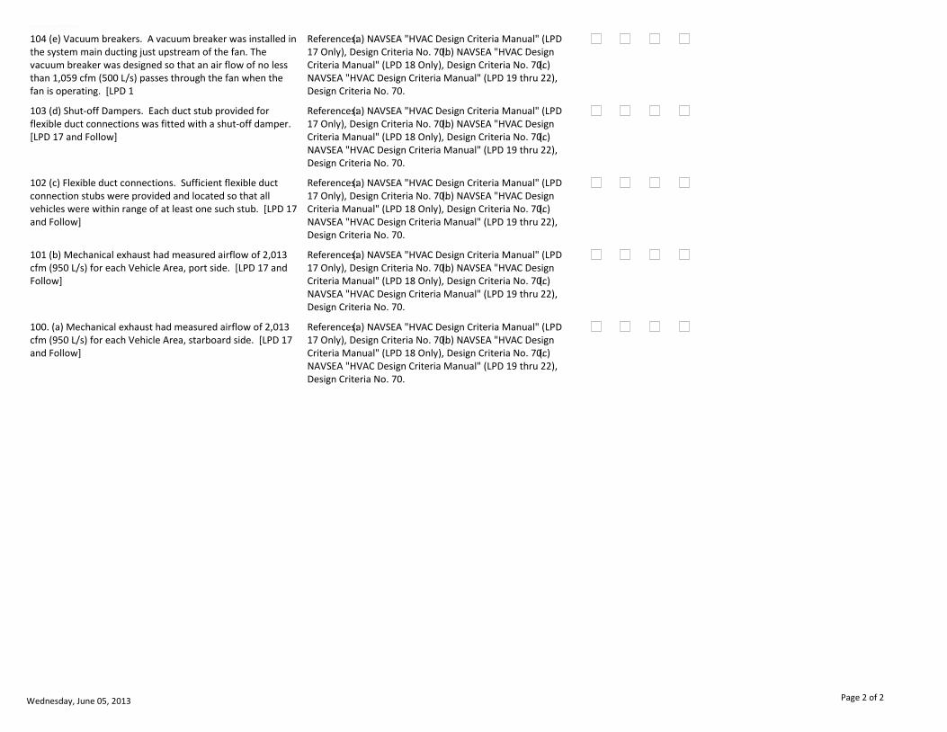
105 (f) Label plates. Label plates were provided to instruct that the damper shall be open when the flexible duct is connected, and closed when the flexible duct is disconnected. [LPD 17 and Follow]
References:(a) NAVSEA "HVAC Design Criteria Manual" (LPD 17 Only), Design Criteria No. 70.(b) NAVSEA "HVAC Design Criteria Manual" (LPD 18 Only), Design Criteria No. 70.(c) NAVSEA "HVAC Design Criteria Manual" (LPD 19 thru 22), Design Criteria No. 70.
Wednesday, June 05, 2013 Page 1 of 2
EQUIPMENT/SYSTEM
104 (e) Vacuum breakers. A vacuum breaker was installed in the system main ducting just upstream of the fan. The vacuum breaker was designed so that an air flow of no less than 1,059 cfm (500 L/s) passes through the fan when the fan is operating. [LPD 1
References:(a) NAVSEA "HVAC Design Criteria Manual" (LPD 17 Only), Design Criteria No. 70.(b) NAVSEA "HVAC Design Criteria Manual" (LPD 18 Only), Design Criteria No. 70.(c) NAVSEA "HVAC Design Criteria Manual" (LPD 19 thru 22), Design Criteria No. 70.
103 (d) Shut-off Dampers. Each duct stub provided for flexible duct connections was fitted with a shut-off damper. [LPD 17 and Follow]
References:(a) NAVSEA "HVAC Design Criteria Manual" (LPD 17 Only), Design Criteria No. 70.(b) NAVSEA "HVAC Design Criteria Manual" (LPD 18 Only), Design Criteria No. 70.(c) NAVSEA "HVAC Design Criteria Manual" (LPD 19 thru 22), Design Criteria No. 70.
102 (c) Flexible duct connections. Sufficient flexible duct connection stubs were provided and located so that all vehicles were within range of at least one such stub. [LPD 17 and Follow]
References:(a) NAVSEA "HVAC Design Criteria Manual" (LPD 17 Only), Design Criteria No. 70.(b) NAVSEA "HVAC Design Criteria Manual" (LPD 18 Only), Design Criteria No. 70.(c) NAVSEA "HVAC Design Criteria Manual" (LPD 19 thru 22), Design Criteria No. 70.
101 (b) Mechanical exhaust had measured airflow of 2,013 cfm (950 L/s) for each Vehicle Area, port side. [LPD 17 and Follow]
References:(a) NAVSEA "HVAC Design Criteria Manual" (LPD 17 Only), Design Criteria No. 70.(b) NAVSEA "HVAC Design Criteria Manual" (LPD 18 Only), Design Criteria No. 70.(c) NAVSEA "HVAC Design Criteria Manual" (LPD 19 thru 22), Design Criteria No. 70.
100. (a) Mechanical exhaust had measured airflow of 2,013 cfm (950 L/s) for each Vehicle Area, starboard side. [LPD 17 and Follow]
References:(a) NAVSEA "HVAC Design Criteria Manual" (LPD 17 Only), Design Criteria No. 70.(b) NAVSEA "HVAC Design Criteria Manual" (LPD 18 Only), Design Criteria No. 70.(c) NAVSEA "HVAC Design Criteria Manual" (LPD 19 thru 22), Design Criteria No. 70.
Wednesday, June 05, 2013 Page 2 of 2
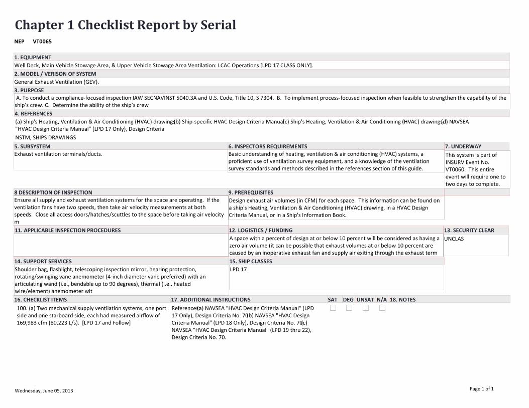
Chapter 1 Checklist Report by SerialVT0065NEP
EQUIPMENT/SYSTEM
Well Deck, Main Vehicle Stowage Area, & Upper Vehicle Stowage Area Ventilation: LCAC Operations [LPD 17 CLASS ONLY].
(a) Ship's Heating, Ventilation & Air Conditioning (HVAC) drawings.(b) Ship-specific HVAC Design Criteria Manual.(c) Ship's Heating, Ventilation & Air Conditioning (HVAC) drawings.(d) NAVSEA "HVAC Design Criteria Manual" (LPD 17 Only), Design Criteria
Exhaust ventilation terminals/ducts.
General Exhaust Ventilation (GEV).
11. APPLICABLE INSPECTION PROCEDURES
3. PURPOSE
5. SUBSYSTEM 6. INSPECTORS REQUIREMENTS
4. REFERENCES
8 DESCRIPTION OF INSPECTION 9. PREREQUISITES
12. LOGISTICS / FUNDING 13. SECURITY CLEAR
14. SUPPORT SERVICES 15. SHIP CLASSES
7. UNDERWAY
2. MODEL / VERISON OF SYSTEM
16. CHECKLIST ITEMS 17. ADDITIONAL INSTRUCTIONS 18. NOTESSAT DEG UNSAT N/A
1. EQIUPMENT
Basic understanding of heating, ventilation & air conditioning (HVAC) systems, a proficient use of ventilation survey equipment, and a knowledge of the ventilation survey standards and methods described in the references section of this guide.
Ensure all supply and exhaust ventilation systems for the space are operating. If the ventilation fans have two speeds, then take air velocity measurements at both speeds. Close all access doors/hatches/scuttles to the space before taking air velocity m
Design exhaust air volumes (in CFM) for each space. This information can be found on a ship's Heating, Ventilation & Air Conditioning (HVAC) drawing, in a HVAC Design Criteria Manual, or in a Ship's Information Book.
Shoulder bag, flashlight, telescoping inspection mirror, hearing protection, rotating/swinging vane anemometer (4-inch diameter vane preferred) with an articulating wand (i.e., bendable up to 90 degrees), thermal (i.e., heated wire/element) anemometer wit
LPD 17
A space with a percent of design at or below 10 percent will be considered as having a zero air volume (it can be possible that exhaust volumes at or below 10 percent are caused by an inoperative exhaust fan and supply air exiting through the exhaust term
NSTM, SHIPS DRAWINGS
A. To conduct a compliance-focused inspection IAW SECNAVINST 5040.3A and U.S. Code, Title 10, S 7304. B. To implement process-focused inspection when feasible to strengthen the capability of the ship’s crew. C. Determine the ability of the ship’s crew
UNCLAS
This system is part of INSURV Event No. VT0060. This entire event will require one to two days to complete.
100. (a) Two mechanical supply ventilation systems, one port side and one starboard side, each had measured airflow of 169,983 cfm (80,223 L/s). [LPD 17 and Follow]
References:(a) NAVSEA "HVAC Design Criteria Manual" (LPD 17 Only), Design Criteria No. 70.(b) NAVSEA "HVAC Design Criteria Manual" (LPD 18 Only), Design Criteria No. 70.(c) NAVSEA "HVAC Design Criteria Manual" (LPD 19 thru 22), Design Criteria No. 70.
Wednesday, June 05, 2013 Page 1 of 1

Chapter 1 Checklist Report by SerialVT0066NEP
EQUIPMENT/SYSTEM
Vehicle Stowage Area Ventilation: Carbon Monoxide Detectors [LPD 17 CLASS ONLY].
(a) Ship's Heating, Ventilation & Air Conditioning (HVAC) drawings.(b) Ship-specific HVAC Design Criteria Manual.(c) Ship's Heating, Ventilation & Air Conditioning (HVAC) drawings.(d) NAVSEA "HVAC Design Criteria Manual" (LPD 17 Only), Design Criteria
Carbon monoxide detectors.
General Exhaust Ventilation (GEV).
11. APPLICABLE INSPECTION PROCEDURES
3. PURPOSE
5. SUBSYSTEM 6. INSPECTORS REQUIREMENTS
4. REFERENCES
8 DESCRIPTION OF INSPECTION 9. PREREQUISITES
12. LOGISTICS / FUNDING 13. SECURITY CLEAR
14. SUPPORT SERVICES 15. SHIP CLASSES
7. UNDERWAY
2. MODEL / VERISON OF SYSTEM
16. CHECKLIST ITEMS 17. ADDITIONAL INSTRUCTIONS 18. NOTESSAT DEG UNSAT N/A
1. EQIUPMENT
Basic understanding of heating, ventilation & air conditioning (HVAC) systems, a proficient use of ventilation survey equipment, and a knowledge of the ventilation survey standards and methods described in the references section of this guide.
TBD. Design exhaust air volumes (in CFM) for each space. This information can be found on a ship's Heating, Ventilation & Air Conditioning (HVAC) drawing, in a HVAC Design Criteria Manual, or in a Ship's Information Book.
Shoulder bag, flashlight, telescoping inspection mirror, hearing protection. LPD 17
If carbon monoxide detectors are inoperative, or not installed, it is a Priority 1 Safety deficiency with a maximum EOC score of 0.2.For Trials, if it was below 90% of design, if carbon monoxide detectors are inoperative, or not installed, it is a Star
NSTM, SHIPS DRAWINGS
A. To conduct a compliance-focused inspection IAW SECNAVINST 5040.3A and U.S. Code, Title 10, S 7304. B. To implement process-focused inspection when feasible to strengthen the capability of the ship’s crew. C. Determine the ability of the ship’s crew
UNCLAS
This system is part of INSURV Event No. VT0060. This entire event will require one to two days to complete.
100. (a) Carbon monoxide detectors were installed in all vehicle areas. [LPD 17, 19 thru 22]
References:(a) NAVSEA "HVAC Design Criteria Manual" (LPD 17 Only), Design Criteria No. 70.(b) NAVSEA "HVAC Design Criteria Manual" (LPD 19 thru 22), Design Criteria No. 70.(c) NAVSEA S9AA0-AB-GOS-010/GSO "General Specifications for Overhaul of Surface
Wednesday, June 05, 2013 Page 1 of 1

Chapter 1 Checklist Report by SerialVT0067NEP
EQUIPMENT/SYSTEM
Well Deck, Main Vehicle Stowage Area, & Upper Vehicle Stowage Area Ventilation: Non-LCAC Operations [LPD 17 CLASS ONLY].
(a) Ship's Heating, Ventilation & Air Conditioning (HVAC) drawings.(b) Ship-specific HVAC Design Criteria Manual.(c) Ship's Heating, Ventilation & Air Conditioning (HVAC) drawings.(d) NAVSEA "HVAC Design Criteria Manual" (LPD 17 Only), Design Criteria
Exhaust ventilation terminals/ducts.
General Exhaust Ventilation (GEV).
11. APPLICABLE INSPECTION PROCEDURES
3. PURPOSE
5. SUBSYSTEM 6. INSPECTORS REQUIREMENTS
4. REFERENCES
8 DESCRIPTION OF INSPECTION 9. PREREQUISITES
12. LOGISTICS / FUNDING 13. SECURITY CLEAR
14. SUPPORT SERVICES 15. SHIP CLASSES
7. UNDERWAY
2. MODEL / VERISON OF SYSTEM
16. CHECKLIST ITEMS 17. ADDITIONAL INSTRUCTIONS 18. NOTESSAT DEG UNSAT N/A
1. EQIUPMENT
Basic understanding of heating, ventilation & air conditioning (HVAC) systems, a proficient use of ventilation survey equipment, and a knowledge of the ventilation survey standards and methods described in the references section of this guide.
Ensure all supply and exhaust ventilation systems for the space are operating. If the ventilation fans have two speeds, then take air velocity measurements at both speeds. Close all access doors/hatches/scuttles to the space before taking air velocity m
Design exhaust air volumes (in CFM) for each space. This information can be found on a ship's Heating, Ventilation & Air Conditioning (HVAC) drawing, in a HVAC Design Criteria Manual, or in a Ship's Information Book.
Shoulder bag, flashlight, telescoping inspection mirror, hearing protection, rotating/swinging vane anemometer (4-inch diameter vane preferred) with an articulating wand (i.e., bendable up to 90 degrees), thermal (i.e., heated wire/element) anemometer wit
LPD 17
A space with a percent of design at or below 10 percent will be considered as having a zero air volume (it can be possible that exhaust volumes at or below 10 percent are caused by an inoperative exhaust fan and supply air exiting through the exhaust term
NSTM, SHIPS DRAWINGS
A. To conduct a compliance-focused inspection IAW SECNAVINST 5040.3A and U.S. Code, Title 10, S 7304. B. To implement process-focused inspection when feasible to strengthen the capability of the ship’s crew. C. Determine the ability of the ship’s crew
UNCLAS
This system is part of INSURV Event No. VT0060. This entire event will require one to two days to complete.
103 (d) Label Plates. Label plates were provided in the aft mooring stations to instruct that during mooring operations, the Well Deck exhaust fans in Fan Rooms 2-189-1 or 2-189-2 may be shutdown while Mooring Station 5 or 6 is manned, respectively. Aft
References:(a) NAVSEA "HVAC Design Criteria Manual" (LPD 17 Only), Design Criteria No. 70.(b) NAVSEA "HVAC Design Criteria Manual" (LPD 18 Only), Design Criteria No. 70.(c) NAVSEA "HVAC Design Criteria Manual" (LPD 19 thru 22), Design Criteria No. 70.
Wednesday, June 05, 2013 Page 1 of 2
EQUIPMENT/SYSTEM
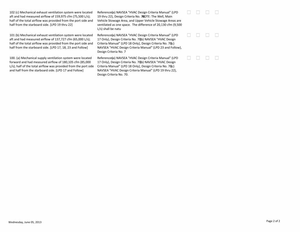
102 (c) Mechanical exhaust ventilation system were located aft and had measured airflow of 159,975 cfm (75,500 L/s); half of the total airflow was provided from the port side and half from the starboard side. [LPD 19 thru 22]
References:(a) NAVSEA "HVAC Design Criteria Manual" (LPD 19 thru 22), Design Criteria No. 70.NOTE: The Well, Main Vehicle Stowage Area, and Upper Vehicle Stowage Areas are ventilated as one space. The difference of 20,130 cfm (9,500 L/s) shall be natu
101 (b) Mechanical exhaust ventilation system were located aft and had measured airflow of 137,727 cfm (65,000 L/s); half of the total airflow was provided from the port side and half from the starboard side. [LPD 17, 18, 23 and Follow]
References:(a) NAVSEA "HVAC Design Criteria Manual" (LPD 17 Only), Design Criteria No. 70.(b) NAVSEA "HVAC Design Criteria Manual" (LPD 18 Only), Design Criteria No. 70.(c) NAVSEA "HVAC Design Criteria Manual" (LPD 23 and Follow), Design Criteria No. 7
100. (a) Mechanical supply ventilation system were located forward and had measured airflow of 180,105 cfm (85,000 L/s); half of the total airflow was provided from the port side and half from the starboard side. [LPD 17 and Follow]
References:(a) NAVSEA "HVAC Design Criteria Manual" (LPD 17 Only), Design Criteria No. 70.(b) NAVSEA "HVAC Design Criteria Manual" (LPD 18 Only), Design Criteria No. 70.(c) NAVSEA "HVAC Design Criteria Manual" (LPD 19 thru 22), Design Criteria No. 70.
Wednesday, June 05, 2013 Page 2 of 2

Chapter 1 Checklist Report by SerialVT0400NEP
EQUIPMENT/SYSTEM
Occupational Health Ventilation Systems: Air Conditioning & Refrigeration Machinery Room.
(a) Ship's Heating, Ventilation & Air Conditioning (HVAC) drawings.(b) Ship-specific HVAC Design Criteria Manual.(c) NAVSEA DWG NO: 802-5959327, HVAC Design Criteria Manual, p. 18-12 (DDG 51 Class only).(d) LHD Ship Specification, Addendum 2, HVAC Desi
Exhaust ventilation terminals/ducts.
General Exhaust Ventilation (GEV).
11. APPLICABLE INSPECTION PROCEDURES
3. PURPOSE
5. SUBSYSTEM 6. INSPECTORS REQUIREMENTS
4. REFERENCES
8 DESCRIPTION OF INSPECTION 9. PREREQUISITES
12. LOGISTICS / FUNDING 13. SECURITY CLEAR
14. SUPPORT SERVICES 15. SHIP CLASSES
7. UNDERWAY
2. MODEL / VERISON OF SYSTEM
16. CHECKLIST ITEMS 17. ADDITIONAL INSTRUCTIONS 18. NOTESSAT DEG UNSAT N/A
1. EQIUPMENT
Basic understanding of heating, ventilation & air conditioning (HVAC) systems, a proficient use of ventilation survey equipment, and a knowledge of the ventilation survey standards and methods described in the references section of this guide.
Ensure all supply and exhaust ventilation systems for the space are operating. If a ship is outfitted with a Chemical Protective System (CPS), and that system is not always set during routine daily operations (e.g., CPS on DDGs is always set), then ensur
Design exhaust air volumes (in CFM) and/or design exhaust air rates of change for each space or hood. This information can be found on a ship's Heating, Ventilation & Air Conditioning (HVAC) drawing, in a HVAC Design Criteria Manual, or in a Ship's Infor
Shoulder bag, flashlight, telescoping inspection mirror, hearing protection, rotating/swinging vane anemometer (4-inch diameter vane preferred) with an articulating wand (i.e., bendable up to 90 degrees), thermal (i.e., heated wire/element) anemometer wit
ALL
A space with a percent of design at or below 10 percent will be considered as having a zero air volume (it can be possible that exhaust volumes at or below 10 percent are caused by an inoperative exhaust fan and supply air exiting through the exhaust term
A. To conduct a compliance-focused inspection IAW SECNAVINST 5040.3A and U.S. Code, Title 10, S 7304. B. To implement process-focused inspection when feasible to strengthen the capability of the ship’s crew. C. Determine the ability of the ship’s crew
UNCLAS
This system is part of OH ventilation under INSURV Event No. VT0040. All of OH ventilation will require two days to complete.
106 (g) Exhaust terminal was located in the overhead. References:(a) NAVSEA 0938-LP-018-0010 - HVAC Design Criteria Manual for Surface Ships, Criteria Sheet 3F.(b) LHD Ship Specification, Addendum 2, HVAC Design Criteria Manual, Criteria Sheet 22.NOTE: An approved Departure from Specification (DFS) is re
Thursday, June 06, 2013 Page 1 of 2

EQUIPMENT/SYSTEM
105 (f) Exhaust terminal was located no more than nine inches above the deck.
References:(a) NAVSEA 0938-LP-018-0010 - HVAC Design Criteria Manual for Surface Ships, Criteria Sheet 3F.(b) NAVSEA DWG NO: 802-5959327, HVAC Design Criteria Manual, p. 18-12 (DDG 51 Class only).(c) LHD Ship Specification, Addendum 2, HVAC Design Crit
104 (e) 1/3 (30 percent for LHD Class) of exhaust quantity was from terminals located nine inches above the deck and near the plant machinery.
References:(a) NAVSEA 0938-LP-018-0010 - HVAC Design Criteria Manual for Surface Ships, Criteria Sheet 3F.(b) LHD Ship Specification, Addendum 2, HVAC Design Criteria Manual, Criteria Sheet 22.NOTE: An approved Departure from Specification (DFS) is re
103 (d) Mechanical supply ventilation system provided one air change every six minutes in the air conditioning / refrigeration machinery room.
(a) NAVSEA 0938-LP-018-0010 - HVAC Design Criteria Manual for Surface Ships, Criteria Sheet 3F.(b) LPD-17 Ship Specification, Addendum 2, HVAC Design Criteria Manual, Criteria Sheet 7.
102 (c) Mechanical exhaust ventilation system provided at least one air change every 15 minutes (i.e., four air changes per hour) in the air conditioning / refrigeration machinery room. [DDG 51 CLASS ONLY]
References:(a) NAVSEA DWG NO: 802-5959327, HVAC Design Criteria Manual, p. 18-12 (DDG 51 Class only).
101 (b) Mechanical supply ventilation system provided one air change every 10 minutes (i.e., six air changes per hour) in the refrigeration machinery room. [LHD CLASS ONLY]
References:(a) LHD Ship Specification, Addendum 2, HVAC Design Criteria Manual, Criteria Sheet 22.
100. (a) Mechanical ventilation system had measured airflow per design criteria.
References:(a) Ship's Heating, Ventilation & Air Conditioning (HVAC) drawings.(b) Ship-specific HVAC Design Criteria Manual.(c) NAVSEA DWG NO: 802-5959327, HVAC Design Criteria Manual, p. 18-12 (DDG 51 Class only).(d) LHD Ship Specification, Addendum
Thursday, June 06, 2013 Page 2 of 2

Chapter 1 Checklist Report by SerialVT0401NEP
EQUIPMENT/SYSTEM
Occupational Health Ventilation Systems: Aviation Composite Material Shop.
(a) Ship's Heating, Ventilation & Air Conditioning (HVAC) drawings.(b) Ship-specific HVAC Design Criteria Manual.(c) NAVSEA 0938-LP-018-0010 - HVAC Design Criteria Manual, Criteria Sheet 4B (Section 3.2).(d) LHD Ship Specification, Addendum 2, HVAC Des
Exhaust ventilation terminals/ducts and flexible exhaust hood.
General Exhaust Ventilation (GEV).
11. APPLICABLE INSPECTION PROCEDURES
3. PURPOSE
5. SUBSYSTEM 6. INSPECTORS REQUIREMENTS
4. REFERENCES
8 DESCRIPTION OF INSPECTION 9. PREREQUISITES
12. LOGISTICS / FUNDING 13. SECURITY CLEAR
14. SUPPORT SERVICES 15. SHIP CLASSES
7. UNDERWAY
2. MODEL / VERISON OF SYSTEM
16. CHECKLIST ITEMS 17. ADDITIONAL INSTRUCTIONS 18. NOTESSAT DEG UNSAT N/A
1. EQIUPMENT
Basic understanding of heating, ventilation & air conditioning (HVAC) systems, a proficient use of ventilation survey equipment, and a knowledge of the ventilation survey standards and methods described in the references section of this guide.
Ensure all supply and exhaust ventilation systems for the space are operating. If a ship is outfitted with a Chemical Protective System (CPS), and that system is not always set during routine daily operations (e.g., CPS on DDGs is always set), then ensur
Design exhaust air volumes (in CFM) for each space or hood. This information can be found on a ship's Heating, Ventilation & Air Conditioning (HVAC) drawing, in a HVAC Design Criteria Manual, or in a Ship's Information Book.
Shoulder bag, flashlight rated as intrinsically safe for hazardous locations, telescoping inspection mirror, hearing protection, rotating/swinging vane anemometer (4-inch diameter vane preferred) with an articulating wand (i.e., bendable up to 90 degrees)
ALL
A space with a percent of design at or below 10 percent will be considered as having a zero air volume (it can be possible that exhaust volumes at or below 10 percent are caused by an inoperative exhaust fan and supply air exiting through the exhaust term
A. To conduct a compliance-focused inspection IAW SECNAVINST 5040.3A and U.S. Code, Title 10, S 7304. B. To implement process-focused inspection when feasible to strengthen the capability of the ship’s crew. C. Determine the ability of the ship’s crew
UNCLAS
This system is part of OH ventilation under INSURV Event No. VT0040. All of OH ventilation will require two days to complete.
101 (b) Compartment was under negative air pressure (-0.25 inches of water pressure).
References:(a) NAVSEA 0938-LP-018-0010 - HVAC Design Criteria Manual, Criteria Sheet 4B (Section 3.2).(b) LHD Ship Specification, Addendum 2, HVAC Design Criteria Manual, Criteria Sheet 21.NOTE: For purposes of an INSURV inspection, pressure different
100. (a) Compartment was provided with an overboard exhaust rated for a minimum of 300 CFM.
References:(a) NAVSEA 0938-LP-018-0010 - HVAC Design Criteria Manual, Criteria Sheet 4B (Section 3.2).(b) LHD Ship Specification, Addendum 2, HVAC Design Criteria Manual, Criteria Sheet 21.
Thursday, June 06, 2013 Page 1 of 1

Chapter 1 Checklist Report by SerialVT0402NEP
EQUIPMENT/SYSTEM
Occupational Health Ventilation Systems: Battery Charging and Storage Area.
(a) Ship's Heating, Ventilation & Air Conditioning (HVAC) drawings.(b) Ship-specific HVAC Design Criteria Manual.(c) NAVSEA 0938-LP-018-0010 - HVAC Design Criteria Manual, Criteria Sheets 3L/4L/13J.(d) NAVSEA DWG NO: 802-5959327, HVAC Design Criteria M
Exhaust ventilation terminals/ducts.
General Exhaust Ventilation (GEV).
11. APPLICABLE INSPECTION PROCEDURES
3. PURPOSE
5. SUBSYSTEM 6. INSPECTORS REQUIREMENTS
4. REFERENCES
8 DESCRIPTION OF INSPECTION 9. PREREQUISITES
12. LOGISTICS / FUNDING 13. SECURITY CLEAR
14. SUPPORT SERVICES 15. SHIP CLASSES
7. UNDERWAY
2. MODEL / VERISON OF SYSTEM
16. CHECKLIST ITEMS 17. ADDITIONAL INSTRUCTIONS 18. NOTESSAT DEG UNSAT N/A
1. EQIUPMENT
Basic understanding of heating, ventilation & air conditioning (HVAC) systems, a proficient use of ventilation survey equipment, and a knowledge of the ventilation survey standards and methods described in the references section of this guide.
NOTE: The hazard is the production of hydrogen gas during battery charging. Gel-type lead acid batteries that are valve-regulated lead acid (VRLA) are maintenance-free and require no ventilation; however, areas where batteries are stored vice in a charg
Design exhaust air volumes (in CFM) and/or design exhaust air rates of change for each space or hood. This information can be found on a ship's Heating, Ventilation & Air Conditioning (HVAC) drawing, in a HVAC Design Criteria Manual, or in a Ship's Infor
Shoulder bag, flashlight rated as intrinsically safe for hazardous locations, telescoping inspection mirror, hearing protection, rotating/swinging vane anemometer (4-inch diameter vane preferred) with an articulating wand (i.e., bendable up to 90 degrees)
ALL
A space with a percent of design at or below 10 percent will be considered as having a zero air volume (it can be possible that exhaust volumes at or below 10 percent are caused by an inoperative exhaust fan and supply air exiting through the exhaust term
A. To conduct a compliance-focused inspection IAW SECNAVINST 5040.3A and U.S. Code, Title 10, S 7304. B. To implement process-focused inspection when feasible to strengthen the capability of the ship’s crew. C. Determine the ability of the ship’s crew
UNCLAS
This system is part of OH ventilation under INSURV Event No. VT0040. All of OH ventilation will require two days to complete.
108 (i) There was at least one exhaust terminal located over the charging racks in the Aviation Alkaline Battery Shop. Minimum air flow for each terminal was 75 CFM. [LHD CLASS]
References:(a) LHD Ship Specifications, Addendum 2, HVAC Design Criteria Manual, Criteria Sheet 29.NOTE: An approved Departure from Specification (DFS) is required for ships not having an exhaust terminal located over the charging racks in the Aviation
107 (h) Exhaust ventilation flow was from alkaline to acid type batteries, if both types were stored in the compartment.
References:(a) NAVSEA 0938-LP-018-0010 - HVAC Design Criteria Manual, Criteria Sheet 4L.(b) NAVSEA DWG NO: 802-5959327, HVAC Design Criteria Manual, p. 18-55 (DDG 51 Class).
Wednesday, June 05, 2013 Page 1 of 2

EQUIPMENT/SYSTEM
106 (g) Mechanical exhaust ventilation provided one air change every 10 minutes (i.e., six air changes per hour) in the Lithium Battery Shop when the mechanical damper was partially closed (the rate of change is two minutes when the damper was fully open)
References:(a) LPD-17 Ship Specifications, Addendum 2, HVAC Design Criteria Manual, Criteria Sheet 92.
105 (f) Mechanical exhaust ventilation provided one air change every six minutes (i.e., 10 air changes per hour) in the Forklift Truck Battery Charging Station. [LPD CLASS]
References:(a) LPD-17 Ship Specifications, Addendum 2, HVAC Design Criteria Manual, Criteria Sheet 15.
104 (e) Mechanical exhaust ventilation provided one air change every six minutes (i.e., 10 air changes per hour) in the Pallet Truck Stowage / Charging Station (compartment was not in the CPS envelope). [DDG CLASS]
References:(a) NAVSEA DWG NO: 802-5959327, HVAC Design Criteria Manual, p. 18-55 (DDG 51 Class).
103 (d) Mechanical exhaust ventilation provided one air change every six minutes (i.e., 10 air changes per hour) in the Storage Battery Shop (non-gel type lead acid batteries).
References:(a) NAVSEA 0938-LP-018-0010 - HVAC Design Criteria Manual, Criteria Sheet 4L.(b) LHD Ship Specifications, Addendum 2, HVAC Design Criteria Manual, Criteria Sheet 26.(c) LPD-17 Ship Specifications, Addendum 2, HVAC Design Criteria Manual, Cri
102 (c) Mechanical exhaust ventilation provided one air change every six minutes (i.e., 10 air changes per hour) in spaces containing battery charging racks.
References:(a) NAVSEA 0938-LP-018-0010 - HVAC Design Criteria Manual, Criteria Sheet 3L.
101 (b) Mechanical exhaust ventilation provided one air change every 10 minutes (i.e., six air changes per hour) in the battery storage area (batteries are not being charged).
References:(a) Ship's Heating, Ventilation & Air Conditioning (HVAC) drawings.(b) Ship-specific HVAC Design Criteria Manual.(c) NAVSEA 0938-LP-018-0010 - HVAC Design Criteria Manual, Criteria Sheets 3L/4L/13J.(d) NAVSEA DWG NO: 802-5959327, HVAC Desig
100. (a) Mechanical ventilation system had measured airflow per design criteria.
References:(a) Ship's Heating, Ventilation & Air Conditioning (HVAC) drawings.(b) Ship-specific HVAC Design Criteria Manual.(c) NAVSEA 0938-LP-018-0010 - HVAC Design Criteria Manual, Criteria Sheets 3L/4L/13J.(d) NAVSEA DWG NO: 802-5959327, HVAC Desig
Wednesday, June 05, 2013 Page 2 of 2
Chapter 1 Checklist Report by SerialVT0403NEP
EQUIPMENT/SYSTEM
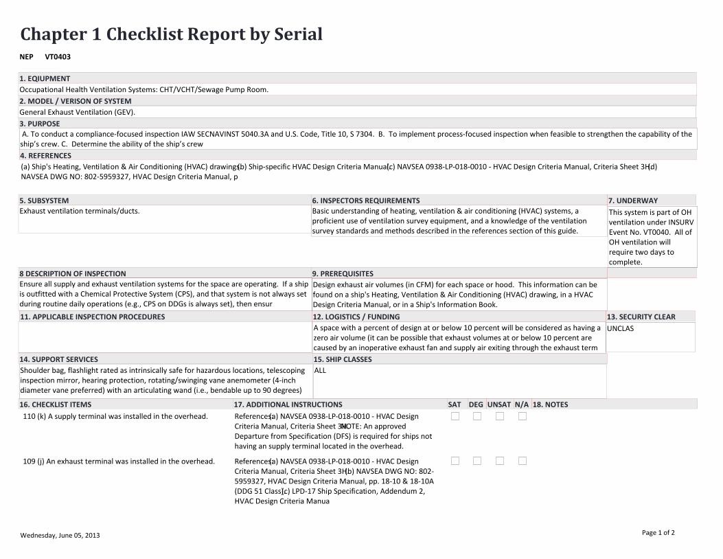
Occupational Health Ventilation Systems: CHT/VCHT/Sewage Pump Room.
(a) Ship's Heating, Ventilation & Air Conditioning (HVAC) drawings.(b) Ship-specific HVAC Design Criteria Manual.(c) NAVSEA 0938-LP-018-0010 - HVAC Design Criteria Manual, Criteria Sheet 3H.(d) NAVSEA DWG NO: 802-5959327, HVAC Design Criteria Manual, p
Exhaust ventilation terminals/ducts.
General Exhaust Ventilation (GEV).
11. APPLICABLE INSPECTION PROCEDURES
3. PURPOSE
5. SUBSYSTEM 6. INSPECTORS REQUIREMENTS
4. REFERENCES
8 DESCRIPTION OF INSPECTION 9. PREREQUISITES
12. LOGISTICS / FUNDING 13. SECURITY CLEAR
14. SUPPORT SERVICES 15. SHIP CLASSES
7. UNDERWAY
2. MODEL / VERISON OF SYSTEM
16. CHECKLIST ITEMS 17. ADDITIONAL INSTRUCTIONS 18. NOTESSAT DEG UNSAT N/A
1. EQIUPMENT
Basic understanding of heating, ventilation & air conditioning (HVAC) systems, a proficient use of ventilation survey equipment, and a knowledge of the ventilation survey standards and methods described in the references section of this guide.
Ensure all supply and exhaust ventilation systems for the space are operating. If a ship is outfitted with a Chemical Protective System (CPS), and that system is not always set during routine daily operations (e.g., CPS on DDGs is always set), then ensur
Design exhaust air volumes (in CFM) for each space or hood. This information can be found on a ship's Heating, Ventilation & Air Conditioning (HVAC) drawing, in a HVAC Design Criteria Manual, or in a Ship's Information Book.
Shoulder bag, flashlight rated as intrinsically safe for hazardous locations, telescoping inspection mirror, hearing protection, rotating/swinging vane anemometer (4-inch diameter vane preferred) with an articulating wand (i.e., bendable up to 90 degrees)
ALL
A space with a percent of design at or below 10 percent will be considered as having a zero air volume (it can be possible that exhaust volumes at or below 10 percent are caused by an inoperative exhaust fan and supply air exiting through the exhaust term
A. To conduct a compliance-focused inspection IAW SECNAVINST 5040.3A and U.S. Code, Title 10, S 7304. B. To implement process-focused inspection when feasible to strengthen the capability of the ship’s crew. C. Determine the ability of the ship’s crew
UNCLAS
This system is part of OH ventilation under INSURV Event No. VT0040. All of OH ventilation will require two days to complete.
110 (k) A supply terminal was installed in the overhead. References:(a) NAVSEA 0938-LP-018-0010 - HVAC Design Criteria Manual, Criteria Sheet 3H.NOTE: An approved Departure from Specification (DFS) is required for ships not having an supply terminal located in the overhead.
109 (j) An exhaust terminal was installed in the overhead. References:(a) NAVSEA 0938-LP-018-0010 - HVAC Design Criteria Manual, Criteria Sheet 3H.(b) NAVSEA DWG NO: 802-5959327, HVAC Design Criteria Manual, pp. 18-10 & 18-10A (DDG 51 Class).(c) LPD-17 Ship Specification, Addendum 2, HVAC Design Criteria Manua
Wednesday, June 05, 2013 Page 1 of 2
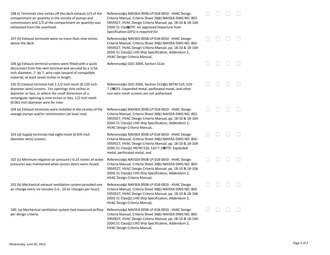
EQUIPMENT/SYSTEM
108 (i) Terminals nine inches off the deck exhaust 2/3 of the compartment air quantity in the vicinity of pumps and comminutors and 1/3 of the compartment air quantity was exhausted from the overhead.
References:(a) NAVSEA 0938-LP-018-0010 - HVAC Design Criteria Manual, Criteria Sheet 3H.(b) NAVSEA DWG NO: 802-5959327, HVAC Design Criteria Manual, pp. 18-10 & 18-10A (DDG 51 Class).NOTE: An approved Departure from Specification (DFS) is required for
107 (h) Exhaust terminals were no more than nine inches above the deck.
References:(a) NAVSEA 0938-LP-018-0010 - HVAC Design Criteria Manual, Criteria Sheet 3H.(b) NAVSEA DWG NO: 802-5959327, HVAC Design Criteria Manual, pp. 18-10 & 18-10A (DDG 51 Class).(c) LHD Ship Specification, Addendum 2, HVAC Design Criteria Manual,
106 (g) Exhaust terminal screens were fitted with a quick disconnect from the vent terminal and secured by a 1/16-inch diameter, 7- by 7- wire rope lanyard of compatible material, at least seven inches in length.
References:(a) GSO 2004, Section 512e.
105 (f) Exhaust terminal had 1-1/2 inch mesh (0.120 inch diameter wire) screens. For openings nine inches in diameter or less, or where the small dimension of a rectangular opening is nine inches or less, 1/2 inch mesh (0.063 inch diameter wire for inter
References:(a) GSO 2004, Section 512e.(b) NSTM 510, 510-7.1.9.NOTE: Expanded metal, perforated metal, and other non-wire mesh screens are not authorized.
104 (e) Exhaust terminals were installed in the vicinity of the sewage pumps and/or comminutors (at least one).
References:(a) NAVSEA 0938-LP-018-0010 - HVAC Design Criteria Manual, Criteria Sheet 3H.(b) NAVSEA DWG NO: 802-5959327, HVAC Design Criteria Manual, pp. 18-10 & 18-10A (DDG 51 Class).(c) LHD Ship Specification, Addendum 2, HVAC Design Criteria Manual,
103 (d) Supply terminals had eight-mesh (0.035 inch diameter wire) screens.
References:(a) NAVSEA 0938-LP-018-0010 - HVAC Design Criteria Manual, Criteria Sheet 3H.(b) NAVSEA DWG NO: 802-5959327, HVAC Design Criteria Manual, pp. 18-10 & 18-10A (DDG 51 Class).(c) NSTM 510, 510-7.1.9.NOTE: Expanded metal, perforated metal, and
102 (c) Minimum negative air pressure (-0.25 inches of water pressure) was maintained when access doors were closed.
References:(a) NAVSEA 0938-LP-018-0010 - HVAC Design Criteria Manual, Criteria Sheet 3H.(b) NAVSEA DWG NO: 802-5959327, HVAC Design Criteria Manual, pp. 18-10 & 18-10A (DDG 51 Class).(c) LHD Ship Specification, Addendum 2, HVAC Design Criteria Manual,
101 (b) Mechanical exhaust ventilation system provided one air change every six minutes (i.e., 10 air changes per hour).
References:(a) NAVSEA 0938-LP-018-0010 - HVAC Design Criteria Manual, Criteria Sheet 3H.(b) NAVSEA DWG NO: 802-5959327, HVAC Design Criteria Manual, pp. 18-10 & 18-10A (DDG 51 Class).(c) LHD Ship Specification, Addendum 2, HVAC Design Criteria Manual,
100. (a) Mechanical ventilation system had measured airflow per design criteria.
References:(a) NAVSEA 0938-LP-018-0010 - HVAC Design Criteria Manual, Criteria Sheet 3H.(b) NAVSEA DWG NO: 802-5959327, HVAC Design Criteria Manual, pp. 18-10 & 18-10A (DDG 51 Class).(c) LHD Ship Specification, Addendum 2, HVAC Design Criteria Manual,
Wednesday, June 05, 2013 Page 2 of 2
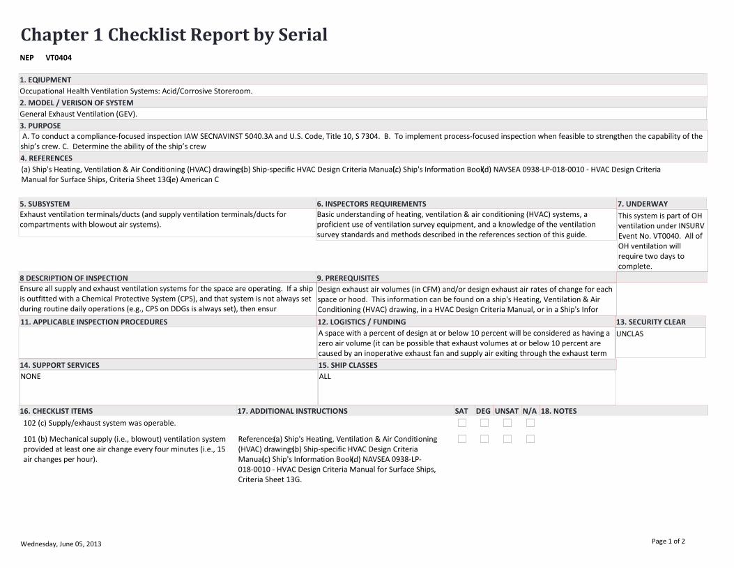
Chapter 1 Checklist Report by SerialVT0404NEP
EQUIPMENT/SYSTEM
Occupational Health Ventilation Systems: Acid/Corrosive Storeroom.
(a) Ship's Heating, Ventilation & Air Conditioning (HVAC) drawings.(b) Ship-specific HVAC Design Criteria Manual.(c) Ship's Information Book.(d) NAVSEA 0938-LP-018-0010 - HVAC Design Criteria Manual for Surface Ships, Criteria Sheet 13G.(e) American C
Exhaust ventilation terminals/ducts (and supply ventilation terminals/ducts for compartments with blowout air systems).
General Exhaust Ventilation (GEV).
11. APPLICABLE INSPECTION PROCEDURES
3. PURPOSE
5. SUBSYSTEM 6. INSPECTORS REQUIREMENTS
4. REFERENCES
8 DESCRIPTION OF INSPECTION 9. PREREQUISITES
12. LOGISTICS / FUNDING 13. SECURITY CLEAR
14. SUPPORT SERVICES 15. SHIP CLASSES
7. UNDERWAY
2. MODEL / VERISON OF SYSTEM
16. CHECKLIST ITEMS 17. ADDITIONAL INSTRUCTIONS 18. NOTESSAT DEG UNSAT N/A
1. EQIUPMENT
Basic understanding of heating, ventilation & air conditioning (HVAC) systems, a proficient use of ventilation survey equipment, and a knowledge of the ventilation survey standards and methods described in the references section of this guide.
Ensure all supply and exhaust ventilation systems for the space are operating. If a ship is outfitted with a Chemical Protective System (CPS), and that system is not always set during routine daily operations (e.g., CPS on DDGs is always set), then ensur
Design exhaust air volumes (in CFM) and/or design exhaust air rates of change for each space or hood. This information can be found on a ship's Heating, Ventilation & Air Conditioning (HVAC) drawing, in a HVAC Design Criteria Manual, or in a Ship's Infor
NONE ALL
A space with a percent of design at or below 10 percent will be considered as having a zero air volume (it can be possible that exhaust volumes at or below 10 percent are caused by an inoperative exhaust fan and supply air exiting through the exhaust term
A. To conduct a compliance-focused inspection IAW SECNAVINST 5040.3A and U.S. Code, Title 10, S 7304. B. To implement process-focused inspection when feasible to strengthen the capability of the ship’s crew. C. Determine the ability of the ship’s crew
UNCLAS
This system is part of OH ventilation under INSURV Event No. VT0040. All of OH ventilation will require two days to complete.
102 (c) Supply/exhaust system was operable.
101 (b) Mechanical supply (i.e., blowout) ventilation system provided at least one air change every four minutes (i.e., 15 air changes per hour).
References:(a) Ship's Heating, Ventilation & Air Conditioning (HVAC) drawings.(b) Ship-specific HVAC Design Criteria Manual.(c) Ship's Information Book.(d) NAVSEA 0938-LP-018-0010 - HVAC Design Criteria Manual for Surface Ships, Criteria Sheet 13G.
Wednesday, June 05, 2013 Page 1 of 2
EQUIPMENT/SYSTEM
100. (a) Mechanical ventilation system had measured airflow per design criteria.
References:(a) Ship's Heating, Ventilation & Air Conditioning (HVAC) drawings.(b) Ship-specific HVAC Design Criteria Manual.(c) Ship's Information Book.(d) NAVSEA 0938-LP-018-0010 - HVAC Design Criteria Manual for Surface Ships, Criteria Sheet 13G.
Wednesday, June 05, 2013 Page 2 of 2
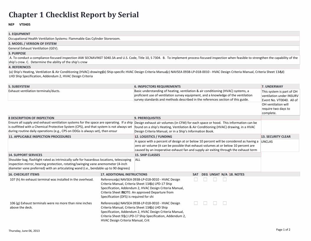
Chapter 1 Checklist Report by SerialVT0405NEP
EQUIPMENT/SYSTEM
Occupational Health Ventilation Systems: Flammable Gas Cylinder Storeroom.
(a) Ship's Heating, Ventilation & Air Conditioning (HVAC) drawings.(b) Ship-specific HVAC Design Criteria Manual.(c) NAVSEA 0938-LP-018-0010 - HVAC Design Criteria Manual, Criteria Sheet 13A.(d) LHD Ship Specification, Addendum 2, HVAC Design Criteria
Exhaust ventilation terminals/ducts.
General Exhaust Ventilation (GEV).
11. APPLICABLE INSPECTION PROCEDURES
3. PURPOSE
5. SUBSYSTEM 6. INSPECTORS REQUIREMENTS
4. REFERENCES
8 DESCRIPTION OF INSPECTION 9. PREREQUISITES
12. LOGISTICS / FUNDING 13. SECURITY CLEAR
14. SUPPORT SERVICES 15. SHIP CLASSES
7. UNDERWAY
2. MODEL / VERISON OF SYSTEM
16. CHECKLIST ITEMS 17. ADDITIONAL INSTRUCTIONS 18. NOTESSAT DEG UNSAT N/A
1. EQIUPMENT
Basic understanding of heating, ventilation & air conditioning (HVAC) systems, a proficient use of ventilation survey equipment, and a knowledge of the ventilation survey standards and methods described in the references section of this guide.
Ensure all supply and exhaust ventilation systems for the space are operating. If a ship is outfitted with a Chemical Protective System (CPS), and that system is not always set during routine daily operations (e.g., CPS on DDGs is always set), then ensur
Design exhaust air volumes (in CFM) for each space or hood. This information can be found on a ship's Heating, Ventilation & Air Conditioning (HVAC) drawing, in a HVAC Design Criteria Manual, or in a Ship's Information Book.
Shoulder bag, flashlight rated as intrinsically safe for hazardous locations, telescoping inspection mirror, hearing protection, rotating/swinging vane anemometer (4-inch diameter vane preferred) with an articulating wand (i.e., bendable up to 90 degrees)
ALL
A space with a percent of design at or below 10 percent will be considered as having a zero air volume (it can be possible that exhaust volumes at or below 10 percent are caused by an inoperative exhaust fan and supply air exiting through the exhaust term
A. To conduct a compliance-focused inspection IAW SECNAVINST 5040.3A and U.S. Code, Title 10, S 7304. B. To implement process-focused inspection when feasible to strengthen the capability of the ship’s crew. C. Determine the ability of the ship’s crew
UNCLAS
This system is part of OH ventilation under INSURV Event No. VT0040. All of OH ventilation will require two days to complete.
107 (h) An exhaust terminal was installed in the overhead. References:(a) NAVSEA 0938-LP-018-0010 - HVAC Design Criteria Manual, Criteria Sheet 13A.(b) LPD-17 Ship Specification, Addendum 2, HVAC Design Criteria Manual, Criteria Sheet 81.NOTE: An approved Departure from Specification (DFS) is required for shi
106 (g) Exhaust terminals were no more than nine inches above the deck.
References:(a) NAVSEA 0938-LP-018-0010 - HVAC Design Criteria Manual, Criteria Sheet 13A.(b) LHD Ship Specification, Addendum 2, HVAC Design Criteria Manual, Criteria Sheet 91.(c) LPD-17 Ship Specification, Addendum 2, HVAC Design Criteria Manual, Crit
Thursday, June 06, 2013 Page 1 of 2
EQUIPMENT/SYSTEM
105 (f) Exhaust terminal screens were fitted with a quick disconnect from the vent terminal and secured by a 1/16-inch diameter, 7- by 7- wire rope lanyard of compatible material, at least 7 inches in length.
References:(a) GSO 2004, Section 512e.
104 (e) Exhaust terminal had 1-1/2 inch mesh (0.120 inch diameter wire) screens. For openings nine inches in diameter or less, or where the small dimension of a rectangular opening is nine inches or less, 1/2 inch mesh (0.063 inch diameter wire for inter
References:(a) GSO 2004, Section 512e.(b) NSTM 510, 510-7.1.9.NOTE: Expanded metal, perforated metal, and other non-wire mesh screens are not authorized.
103 (d) Supply terminals had eight-mesh (0.035 inch diameter wire) screens.
References:(a) NAVSEA 0938-LP-018-0010 - HVAC Design Criteria Manual, Criteria Sheet 13A.(b) NSTM 510, 510-7.1.9.NOTE: Expanded metal, perforated metal, and other non-wire mesh screens are not authorized.
102 (c) Minimum negative air pressure (-0.25 inches of water pressure) was maintained when access doors were closed.
References:(a) NAVSEA 0938-LP-018-0010 - HVAC Design Criteria Manual, Criteria Sheet 13A.(b) LHD Ship Specification, Addendum 2, HVAC Design Criteria Manual, Criteria Sheet 91.(c) LPD-17 Ship Specification, Addendum 2, HVAC Design Criteria Manual, Crit
101 (b) Mechanical exhaust ventilation system provided one air change every four minutes (i.e., 15 air changes per hour).
References:(a) NAVSEA 0938-LP-018-0010 - HVAC Design Criteria Manual, Criteria Sheet 13A.(b) LHD Ship Specification, Addendum 2, HVAC Design Criteria Manual, Criteria Sheet 91.(c) LPD-17 Ship Specification, Addendum 2, HVAC Design Criteria Manual, Crit
100. (a) Mechanical ventilation system had measured airflow per design criteria.
References:(a) NAVSEA 0938-LP-018-0010 - HVAC Design Criteria Manual, Criteria Sheet 13A.(b) LHD Ship Specification, Addendum 2, HVAC Design Criteria Manual, Criteria Sheet 91.(c) LPD-17 Ship Specification, Addendum 2, HVAC Design Criteria Manual, Crit
Thursday, June 06, 2013 Page 2 of 2

Chapter 1 Checklist Report by SerialVT0406NEP
EQUIPMENT/SYSTEM
Occupational Health Ventilation Systems: Flammable Liquid Storeroom.
(a) Ship's Heating, Ventilation & Air Conditioning (HVAC) drawings.(b) Ship-specific HVAC Design Criteria Manual.(c) NAVSEA 0938-LP-018-0010 - HVAC Design Criteria Manual, Criteria Sheet 13A.(d) NAVSEA DWG NO: 802-5959327, HVAC Design Criteria Manual,
Exhaust ventilation terminals/ducts.
General Exhaust Ventilation (GEV).
11. APPLICABLE INSPECTION PROCEDURES
3. PURPOSE
5. SUBSYSTEM 6. INSPECTORS REQUIREMENTS
4. REFERENCES
8 DESCRIPTION OF INSPECTION 9. PREREQUISITES
12. LOGISTICS / FUNDING 13. SECURITY CLEAR
14. SUPPORT SERVICES 15. SHIP CLASSES
7. UNDERWAY
2. MODEL / VERISON OF SYSTEM
16. CHECKLIST ITEMS 17. ADDITIONAL INSTRUCTIONS 18. NOTESSAT DEG UNSAT N/A
1. EQIUPMENT
Basic understanding of heating, ventilation & air conditioning (HVAC) systems, a proficient use of ventilation survey equipment, and a knowledge of the ventilation survey standards and methods described in the references section of this guide.
Ensure all supply and exhaust ventilation systems for the space are operating. If a ship is outfitted with a Chemical Protective System (CPS), and that system is not always set during routine daily operations (e.g., CPS on DDGs is always set), then ensur
Design exhaust air volumes (in CFM) for each space or hood. This information can be found on a ship's Heating, Ventilation & Air Conditioning (HVAC) drawing, in a HVAC Design Criteria Manual, or in a Ship's Information Book.
Shoulder bag, flashlight rated as intrinsically safe for hazardous locations, telescoping inspection mirror, hearing protection, rotating/swinging vane anemometer (4-inch diameter vane preferred) with an articulating wand (i.e., bendable up to 90 degrees)
ALL
A space with a percent of design at or below 10 percent will be considered as having a zero air volume (it can be possible that exhaust volumes at or below 10 percent are caused by an inoperative exhaust fan and supply air exiting through the exhaust term
A. To conduct a compliance-focused inspection IAW SECNAVINST 5040.3A and U.S. Code, Title 10, S 7304. B. To implement process-focused inspection when feasible to strengthen the capability of the ship’s crew. C. Determine the ability of the ship’s crew
UNCLAS
This system is part of OH ventilation under INSURV Event No. VT0040. All of OH ventilation will require two days to complete.
107 (h) An exhaust terminal was installed in the overhead. References:(a) NAVSEA 0938-LP-018-0010 - HVAC Design Criteria Manual, Criteria Sheet 13A.(b) NAVSEA DWG NO: 802-5959327, HVAC Design Criteria Manual, pp. 18-65 & 18-65A (DDG 51 Class).(c) LPD-17 Ship Specification, Addendum 2, HVAC Design Criteria Manu
106 (g) Exhaust terminals were no more than nine inches above the deck.
References:(a) NAVSEA 0938-LP-018-0010 - HVAC Design Criteria Manual, Criteria Sheet 13A.(b) NAVSEA DWG NO: 802-5959327, HVAC Design Criteria Manual, pp. 18-65 & 18-65A (DDG 51 Class).(c) LHD Ship Specification, Addendum 2, HVAC Design Criteria Manual,
Thursday, June 06, 2013 Page 1 of 2

EQUIPMENT/SYSTEM
105 (f) Exhaust terminal screens were fitted with a quick disconnect from the vent terminal and secured by a 1/16-inch diameter, 7- by 7- wire rope lanyard of compatible material, at least 7 inches in length.
References:(a) GSO 2004, Section 512e.
104 (e) Exhaust terminal had 1-1/2 inch mesh (0.120 inch diameter wire) screens. For openings nine inches in diameter or less, or where the small dimension of a rectangular opening is nine inches or less, 1/2 inch mesh (0.063 inch diameter wire for inter
References:(a) GSO 2004, Section 512e.(b) NSTM 510, 510-7.1.9.NOTE: Expanded metal, perforated metal, and other non-wire mesh screens are not authorized.
103 (d) Supply terminals had eight-mesh (0.035 inch diameter wire) screens.
References:(a) NAVSEA 0938-LP-018-0010 - HVAC Design Criteria Manual, Criteria Sheet 13A.(b) NAVSEA DWG NO: 802-5959327, HVAC Design Criteria Manual, pp. 18-65 & 18-65A (DDG 51 Class).(c) NSTM 510, 510-7.1.9.NOTE: Expanded metal, perforated metal, an
102 (c) Minimum negative air pressure (-0.25 inches of water pressure) was maintained when access doors were closed.
References:(a) NAVSEA 0938-LP-018-0010 - HVAC Design Criteria Manual, Criteria Sheet 13A.(b) NAVSEA DWG NO: 802-5959327, HVAC Design Criteria Manual, pp. 18-65 & 18-65A (DDG 51 Class).(c) LHD Ship Specification, Addendum 2, HVAC Design Criteria Manual,
101 (b) Mechanical exhaust ventilation system provided one air change every four minutes (i.e., 15 air changes per hour).
References:(a) NAVSEA 0938-LP-018-0010 - HVAC Design Criteria Manual, Criteria Sheet 13A.(b) NAVSEA DWG NO: 802-5959327, HVAC Design Criteria Manual, pp. 18-65 & 18-65A (DDG 51 Class).(c) LHD Ship Specification, Addendum 2, HVAC Design Criteria Manual,
100. (a) Mechanical ventilation system had measured airflow per design criteria.
References:(a) NAVSEA 0938-LP-018-0010 - HVAC Design Criteria Manual, Criteria Sheet 13A.(b) NAVSEA DWG NO: 802-5959327, HVAC Design Criteria Manual, pp. 18-65 & 18-65A (DDG 51 Class).(c) LHD Ship Specification, Addendum 2, HVAC Design Criteria Manual,
Thursday, June 06, 2013 Page 2 of 2
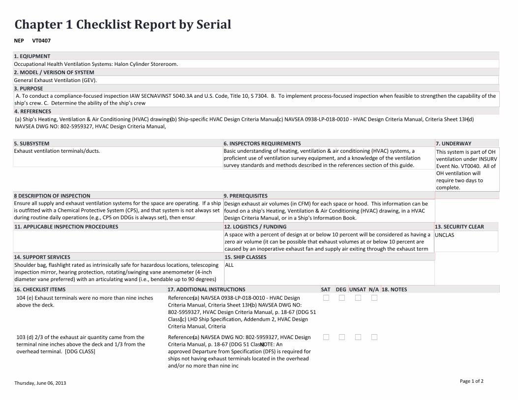
Chapter 1 Checklist Report by SerialVT0407NEP
EQUIPMENT/SYSTEM
Occupational Health Ventilation Systems: Halon Cylinder Storeroom.
(a) Ship's Heating, Ventilation & Air Conditioning (HVAC) drawings.(b) Ship-specific HVAC Design Criteria Manual.(c) NAVSEA 0938-LP-018-0010 - HVAC Design Criteria Manual, Criteria Sheet 13H.(d) NAVSEA DWG NO: 802-5959327, HVAC Design Criteria Manual,
Exhaust ventilation terminals/ducts.
General Exhaust Ventilation (GEV).
11. APPLICABLE INSPECTION PROCEDURES
3. PURPOSE
5. SUBSYSTEM 6. INSPECTORS REQUIREMENTS
4. REFERENCES
8 DESCRIPTION OF INSPECTION 9. PREREQUISITES
12. LOGISTICS / FUNDING 13. SECURITY CLEAR
14. SUPPORT SERVICES 15. SHIP CLASSES
7. UNDERWAY
2. MODEL / VERISON OF SYSTEM
16. CHECKLIST ITEMS 17. ADDITIONAL INSTRUCTIONS 18. NOTESSAT DEG UNSAT N/A
1. EQIUPMENT
Basic understanding of heating, ventilation & air conditioning (HVAC) systems, a proficient use of ventilation survey equipment, and a knowledge of the ventilation survey standards and methods described in the references section of this guide.
Ensure all supply and exhaust ventilation systems for the space are operating. If a ship is outfitted with a Chemical Protective System (CPS), and that system is not always set during routine daily operations (e.g., CPS on DDGs is always set), then ensur
Design exhaust air volumes (in CFM) for each space or hood. This information can be found on a ship's Heating, Ventilation & Air Conditioning (HVAC) drawing, in a HVAC Design Criteria Manual, or in a Ship's Information Book.
Shoulder bag, flashlight rated as intrinsically safe for hazardous locations, telescoping inspection mirror, hearing protection, rotating/swinging vane anemometer (4-inch diameter vane preferred) with an articulating wand (i.e., bendable up to 90 degrees)
ALL
A space with a percent of design at or below 10 percent will be considered as having a zero air volume (it can be possible that exhaust volumes at or below 10 percent are caused by an inoperative exhaust fan and supply air exiting through the exhaust term
A. To conduct a compliance-focused inspection IAW SECNAVINST 5040.3A and U.S. Code, Title 10, S 7304. B. To implement process-focused inspection when feasible to strengthen the capability of the ship’s crew. C. Determine the ability of the ship’s crew
UNCLAS
This system is part of OH ventilation under INSURV Event No. VT0040. All of OH ventilation will require two days to complete.
104 (e) Exhaust terminals were no more than nine inches above the deck.
References:(a) NAVSEA 0938-LP-018-0010 - HVAC Design Criteria Manual, Criteria Sheet 13H.(b) NAVSEA DWG NO: 802-5959327, HVAC Design Criteria Manual, p. 18-67 (DDG 51 Class).(c) LHD Ship Specification, Addendum 2, HVAC Design Criteria Manual, Criteria
103 (d) 2/3 of the exhaust air quantity came from the terminal nine inches above the deck and 1/3 from the overhead terminal. [DDG CLASS]
References:(a) NAVSEA DWG NO: 802-5959327, HVAC Design Criteria Manual, p. 18-67 (DDG 51 Class).NOTE: An approved Departure from Specification (DFS) is required for ships not having exhaust terminals located in the overhead and/or no more than nine inc
Thursday, June 06, 2013 Page 1 of 2

EQUIPMENT/SYSTEM
102 (c) Mechanical exhaust ventilation system provided at least one air change every four minutes (i.e., 15 airchanges per hour). [LHD AND DDG 51 CLASS ONLY]
References:(a) NAVSEA DWG NO: 802-5959327, HVAC Design Criteria Manual, p. 18-67 (DDG 51 Class).(b) LHD Ship Specification, Addendum 2, HVAC Design Criteria Manual, Criteria Sheet 115.
101 (b) Mechanical exhaust ventilation system provided at least one air change every eight minutes (i.e., 7.5 air changes per hour).
References:(a) NAVSEA 0938-LP-018-0010 - HVAC Design Criteria Manual, Criteria Sheet 13H.
100. (a) Mechanical ventilation system had measured airflow per design criteria.
References:(a) NAVSEA 0938-LP-018-0010 - HVAC Design Criteria Manual, Criteria Sheet 13H.
Thursday, June 06, 2013 Page 2 of 2
Chapter 1 Checklist Report by SerialVT0408NEP
EQUIPMENT/SYSTEM
Occupational Health Ventilation Systems: Hazardous Minimization Center (HAZMINCEN) Issue Room.
(a) Ship's Heating, Ventilation & Air Conditioning (HVAC) drawings.(b) Ship-specific HVAC Design Criteria Manual.(c) NAVSEA 0938-LP-018-0010 - HVAC Design Criteria Manual, Criteria Sheet 13A.(d) NAVSEA DWG NO: 802-5959327, HVAC Design Criteria Manual,
Exhaust ventilation terminals/ducts.
General Exhaust Ventilation (GEV).
11. APPLICABLE INSPECTION PROCEDURES
3. PURPOSE
5. SUBSYSTEM 6. INSPECTORS REQUIREMENTS
4. REFERENCES
8 DESCRIPTION OF INSPECTION 9. PREREQUISITES
12. LOGISTICS / FUNDING 13. SECURITY CLEAR
14. SUPPORT SERVICES 15. SHIP CLASSES
7. UNDERWAY
2. MODEL / VERISON OF SYSTEM
16. CHECKLIST ITEMS 17. ADDITIONAL INSTRUCTIONS 18. NOTESSAT DEG UNSAT N/A
1. EQIUPMENT
Basic understanding of heating, ventilation & air conditioning (HVAC) systems, a proficient use of ventilation survey equipment, and a knowledge of the ventilation survey standards and methods described in the references section of this guide.
Ensure all supply and exhaust ventilation systems for the space are operating. If a ship is outfitted with a Chemical Protective System (CPS), and that system is not always set during routine daily operations (e.g., CPS on DDGs is always set), then ensur
Design exhaust air volumes (in CFM) for each space or hood. This information can be found on a ship's Heating, Ventilation & Air Conditioning (HVAC) drawing, in a HVAC Design Criteria Manual, or in a Ship's Information Book.
Shoulder bag, flashlight rated as intrinsically safe for hazardous locations, telescoping inspection mirror, hearing protection, rotating/swinging vane anemometer (4-inch diameter vane preferred) with an articulating wand (i.e., bendable up to 90 degrees)
ALL
A space with a percent of design at or below 10 percent will be considered as having a zero air volume (it can be possible that exhaust volumes at or below 10 percent are caused by an inoperative exhaust fan and supply air exiting through the exhaust term
A. To conduct a compliance-focused inspection IAW SECNAVINST 5040.3A and U.S. Code, Title 10, S 7304. B. To implement process-focused inspection when feasible to strengthen the capability of the ship’s crew. C. Determine the ability of the ship’s crew
UNCLAS
This system is part of OH ventilation under INSURV Event No. VT0040. All of OH ventilation will require two days to complete.
108 (i) An exhaust terminal was installed in the overhead. References:(a) NAVSEA 0938-LP-018-0010 - HVAC Design Criteria Manual, Criteria Sheet 13A.(b) NAVSEA DWG NO: 802-5959327, HVAC Design Criteria Manual, p. 18-65 & 18-65A (DDG 51 Class).(c) LPD-17 Ship Specification, Addendum 2, HVAC Design Criteria Manua
107 (h) Terminals nine inches off the deck exhaust 2/3 of the compartment air quantity and 1/3 of the compartment air quantity was exhausted from the overhead. [DDG 51 CLASS ONLY]
References:(a) NAVSEA DWG NO: 802-5959327, HVAC Design Criteria Manual, p. 18-65 & 18-65A (DDG 51 Class).NOTE: An approved Departure from Specification (DFS) is required for ships not having exhaust terminals located in the overhead and/or no more than
Thursday, June 06, 2013 Page 1 of 2

EQUIPMENT/SYSTEM
106 (g) Exhaust terminals were no more than nine inches above the deck.
References:(a) NAVSEA 0938-LP-018-0010 - HVAC Design Criteria Manual, Criteria Sheet 13A.(b) NAVSEA DWG NO: 802-5959327, HVAC Design Criteria Manual, p. 18-65 & 18-65A (DDG 51 Class).(c) LHD Ship Specification, Addendum 2, HVAC Design Criteria Manual,
105 (f) Exhaust terminal screens were fitted with a quick disconnect from the vent terminal and secured by a 1/16-inch diameter, 7- by 7- wire rope lanyard of compatible material, at least 7 inches in length.
References:(a) GSO 2004, Section 512e.
104 (e) Exhaust terminal had 1-1/2 inch mesh (0.120 inch diameter wire) screens. For openings nine inches in diameter or less, or where the small dimension of a rectangular opening is nine inches or less, 1/2 inch mesh (0.063 inch diameter wire for inter
References:(a) NSTM 510, 510-7.1.9.(b) GSO 2004, Section 512e.NOTE: Expanded metal, perforated metal, and other non-wire mesh screens are not authorized.
103 (d) Supply terminals had eight-mesh (0.035 inch diameter wire) screens.
References:(a) NAVSEA 0938-LP-018-0010 - HVAC Design Criteria Manual, Criteria Sheet 13A.(b) NAVSEA DWG NO: 802-5959327, HVAC Design Criteria Manual, p. 18-65 & 18-65A (DDG 51 Class).(c) NSTM 510, 510-7.1.9.NOTE: Expanded metal, perforated metal, and
102 (c) Minimum negative air pressure (-0.25 inches of water pressure) was maintained when access doors were closed.
References:(a) NAVSEA 0938-LP-018-0010 - HVAC Design Criteria Manual, Criteria Sheet 13A.(b) NAVSEA DWG NO: 802-5959327, HVAC Design Criteria Manual, p. 18-65 & 18-65A (DDG 51 Class).(c) LHD Ship Specification, Addendum 2, HVAC Design Criteria Manual,
101 (b) Mechanical exhaust ventilation system provided one air change every four minutes (i.e., 15 air changes per hour).
References:(a) NAVSEA 0938-LP-018-0010 - HVAC Design Criteria Manual, Criteria Sheet 13A.(b) NAVSEA DWG NO: 802-5959327, HVAC Design Criteria Manual, p. 18-65 & 18-65A (DDG 51 Class).(c) LHD Ship Specification, Addendum 2, HVAC Design Criteria Manual,
100. (a) Mechanical ventilation system had measured airflow per design criteria.
References:(a) NAVSEA 0938-LP-018-0010 - HVAC Design Criteria Manual, Criteria Sheet 13A.(b) NAVSEA DWG NO: 802-5959327, HVAC Design Criteria Manual, p. 18-65 & 18-65A (DDG 51 Class).(c) LHD Ship Specification, Addendum 2, HVAC Design Criteria Manual,
Thursday, June 06, 2013 Page 2 of 2

Chapter 1 Checklist Report by SerialVT0409NEP
EQUIPMENT/SYSTEM
Occupational Health Ventilation Systems: JP5 Filter Room [CVN Only].
(a) Ship's Heating, Ventilation & Air Conditioning (HVAC) drawings.(b) Ship-specific HVAC Design Criteria Manual.(c) NAVSEA 0938-LP-018-0010 - HVAC Design Criteria Manual, Criteria Sheet 3I.(d) American Conference of Governmental Industrial Hygienists
Exhaust ventilation terminals/ducts.
General Exhaust Ventilation (GEV).
11. APPLICABLE INSPECTION PROCEDURES
3. PURPOSE
5. SUBSYSTEM 6. INSPECTORS REQUIREMENTS
4. REFERENCES
8 DESCRIPTION OF INSPECTION 9. PREREQUISITES
12. LOGISTICS / FUNDING 13. SECURITY CLEAR
14. SUPPORT SERVICES 15. SHIP CLASSES
7. UNDERWAY
2. MODEL / VERISON OF SYSTEM
16. CHECKLIST ITEMS 17. ADDITIONAL INSTRUCTIONS 18. NOTESSAT DEG UNSAT N/A
1. EQIUPMENT
Basic understanding of heating, ventilation & air conditioning (HVAC) systems, a proficient use of ventilation survey equipment, and a knowledge of the ventilation survey standards and methods described in the references section of this guide.
Ensure all supply and exhaust ventilation systems for the space are operating. If a ship is outfitted with a Chemical Protective System (CPS), and that system is not always set during routine daily operations (e.g., CPS on DDGs is always set), then ensur
Design exhaust air volumes (in CFM) for each space or hood. This information can be found on a ship's Heating, Ventilation & Air Conditioning (HVAC) drawing, in a HVAC Design Criteria Manual, or in a Ship's Information Book.
Shoulder bag, flashlight rated as intrinsically safe for hazardous locations, telescoping inspection mirror, hearing protection, rotating/swinging vane anemometer (4-inch diameter vane preferred) with an articulating wand (i.e., bendable up to 90 degrees)
CVN
A space with a percent of design at or below 10 percent will be considered as having a zero air volume (it can be possible that exhaust volumes at or below 10 percent are caused by an inoperative exhaust fan and supply air exiting through the exhaust term
A. To conduct a compliance-focused inspection IAW SECNAVINST 5040.3A and U.S. Code, Title 10, S 7304. B. To implement process-focused inspection when feasible to strengthen the capability of the ship’s crew. C. Determine the ability of the ship’s crew
UNCLAS
This system is part of OH ventilation under INSURV Event No. VT0040. All of OH ventilation will require two days to complete.
103 (d) If the Filter Room was configured with auxiliary equipment (e.g., pumps), 50 percent of the exhaust came from the terminal nine inches above the deck and the other half from above the pump motor.
References:(a) NAVSEA 0938-LP-018-0010 - HVAC Design Criteria Manual, Criteria Sheet 3I.NOTE: An approved Departure from Specification (DFS) is required for ships not having exhaust terminals located in the overhead above the pump motor and/or no more
102 (c) Exhaust terminals were no more than nine inches above the deck.
References:(a) NAVSEA 0938-LP-018-0010 - HVAC Design Criteria Manual, Criteria Sheet 3I.NOTE: An approved Departure from Specification (DFS) is required for ships not having an exhaust terminals located no more than nine inches above the deck.
Thursday, June 06, 2013 Page 1 of 2

EQUIPMENT/SYSTEM
101 (b) Mechanical exhaust ventilation system provided one air change every 10 minutes (i.e., six air changes per hour).
References:(a) NAVSEA 0938-LP-018-0010 - HVAC Design Criteria Manual, Criteria Sheet 3I.
100. (a) Mechanical ventilation system had measured airflow per design criteria.
References:(a) NAVSEA 0938-LP-018-0010 - HVAC Design Criteria Manual, Criteria Sheet 3I.
Thursday, June 06, 2013 Page 2 of 2
Chapter 1 Checklist Report by SerialVT0410NEP
EQUIPMENT/SYSTEM
Occupational Health Ventilation Systems: JP5 Pump Room.
(a) Ship's Heating, Ventilation & Air Conditioning (HVAC) drawings.(b) Ship-specific HVAC Design Criteria Manual.(c) NAVSEA 0938-LP-018-0010 - HVAC Design Criteria Manual, Criteria Sheet 3H.(d) NAVSEA DWG NO: 802-5959327, HVAC Design Criteria Manual, p
Exhaust ventilation terminals/ducts.
General Exhaust Ventilation (GEV).
11. APPLICABLE INSPECTION PROCEDURES
3. PURPOSE
5. SUBSYSTEM 6. INSPECTORS REQUIREMENTS
4. REFERENCES
8 DESCRIPTION OF INSPECTION 9. PREREQUISITES
12. LOGISTICS / FUNDING 13. SECURITY CLEAR
14. SUPPORT SERVICES 15. SHIP CLASSES
7. UNDERWAY
2. MODEL / VERISON OF SYSTEM
16. CHECKLIST ITEMS 17. ADDITIONAL INSTRUCTIONS 18. NOTESSAT DEG UNSAT N/A
1. EQIUPMENT
Basic understanding of heating, ventilation & air conditioning (HVAC) systems, a proficient use of ventilation survey equipment, and a knowledge of the ventilation survey standards and methods described in the references section of this guide.
Ensure all supply and exhaust ventilation systems for the space are operating. If a ship is outfitted with a Chemical Protective System (CPS), and that system is not always set during routine daily operations (e.g., CPS on DDGs is always set), then ensur
Design exhaust air volumes (in CFM) for each space or hood. This information can be found on a ship's Heating, Ventilation & Air Conditioning (HVAC) drawing, in a HVAC Design Criteria Manual, or in a Ship's Information Book.
Shoulder bag, flashlight rated as intrinsically safe for hazardous locations, telescoping inspection mirror, hearing protection, rotating/swinging vane anemometer (4-inch diameter vane preferred) with an articulating wand (i.e., bendable up to 90 degrees)
ALL
A space with a percent of design at or below 10 percent will be considered as having a zero air volume (it can be possible that exhaust volumes at or below 10 percent are caused by an inoperative exhaust fan and supply air exiting through the exhaust term
A. To conduct a compliance-focused inspection IAW SECNAVINST 5040.3A and U.S. Code, Title 10, S 7304. B. To implement process-focused inspection when feasible to strengthen the capability of the ship’s crew. C. Determine the ability of the ship’s crew
UNCLAS
This system is part of OH ventilation under INSURV Event No. VT0040. All of OH ventilation will require two days to complete.
111 (l) Mechanical exhaust and supply ventilation systems maintained minimum negative pressure (-0.25 inches of water pressure) when the hatch/door was closed.
References:(a) NAVSEA 0938-LP-018-0010 - HVAC Design Criteria Manual, Criteria Sheet 3H.(b) LPD-17 Ship Specification, Addendum 2, HVAC Design Criteria Manual, Criteria Sheet 9.NOTE: For purposes of an INSURV inspection, pressure differential can be d
110 (k) Exhaust terminal screens were fitted with a quick disconnect from the vent terminal and secured by a 1/16-inch diameter, 7- by 7- wire rope lanyard of compatible material, at least seven inches in length.
References:(a) GSO 2004, Section 512e.
Thursday, June 06, 2013 Page 1 of 3
EQUIPMENT/SYSTEM
109 (j) Exhaust terminal had 1-1/2 inch mesh (0.120 inch diameter wire) screens. For openings nine inches in diameter or less, or where the small dimension of a rectangular opening is nine inches or less, 1/2 inch mesh (0.063 inch diameter wire for inter
References:(a) GSO 2004, Section 512e.(b) NSTM 510, 510-7.1.9.NOTE: Expanded metal, perforated metal, and other non-wire mesh screens are not authorized.
108 (i) Supply terminals had eight-mesh (0.035 inch diameter wire) screens.
References:(a) NAVSEA 0938-LP-018-0010 - HVAC Design Criteria Manual, Criteria Sheet 3H.(b) NAVSEA DWG NO: 802-5959327, HVAC Design Criteria Manual, pp. 18-5 & 18-5A (DDG 51 Class).(c) NSTM 510, 510-7.1.9.
107 (h) Supply terminal air quantities were equal to the exhaust air quantities for each level in the Generator Room. [DDG 51 CLASS ONLY]
References:(a) NAVSEA DWG NO: 802-5959327, HVAC Design Criteria Manual, pp. 18-5 & 18-5A (DDG 51 Class).
106 (g) Supply terminals were provided on each level of the Generator Room. [DDG 51 CLASS ONLY]
References:(a) NAVSEA DWG NO: 802-5959327, HVAC Design Criteria Manual, pp. 18-5 & 18-5A (DDG 51 Class).NOTE: An approved Departure from Specification (DFS) is required for ships not having supply terminals located on each level of the Generator Room.
105 (f) Supply terminals were provided in the overhead. References:(a) NAVSEA 0938-LP-018-0010 - HVAC Design Criteria Manual, Criteria Sheet 3H.(b) LPD-17 Ship Specification, Addendum 2, HVAC Design Criteria Manual, Criteria Sheet 9.NOTE: An approved Departure from Specification (DFS) is required for ships
104 (e) Exhaust terminals were located in the vicinity of the JP-5 pumps [DDG 51 CLASS, LHD CLASS ONLY].
References:(a) NAVSEA DWG NO: 802-5959327, HVAC Design Criteria Manual, pp. 18-5 & 18-5A (DDG 51 Class).(b) LHD Ship Specification, Addendum 2, HVAC Design Criteria Manual, Criteria Sheet 14.NOTE: An approved Departure from Specification (DFS) is requ
103 (d) An exhaust terminal was installed no more than nine inches above the deck/grating.
References:(a) NAVSEA 0938-LP-018-0010 - HVAC Design Criteria Manual, Criteria Sheet 3H.(b) NAVSEA DWG NO: 802-5959327, HVAC Design Criteria Manual, pp. 18-5 & 18-5A (DDG 51 Class).(c) LHD Ship Specification, Addendum 2, HVAC Design Criteria Manual, Cr
102 (c) Mechanical exhaust ventilation system provided at least one air change every 15 minutes (i.e., four air changes per hour). [DDG 51 CLASS ONLY]
References:(a) NAVSEA DWG NO: 802-5959327, HVAC Design Criteria Manual, pp. 18-5 & 18-5A (DDG 51 Class).
101 (b) Mechanical exhaust ventilation system provided at least one air change every six minutes (i.e., 10 air changes per hour).
References:(a) NAVSEA 0938-LP-018-0010 - HVAC Design Criteria Manual, Criteria Sheet 3H.(b) LHD Ship Specification, Addendum 2, HVAC Design Criteria Manual, Criteria Sheet 14.(c) LPD-17 Ship Specification, Addendum 2, HVAC Design Criteria Manual, Crite
Thursday, June 06, 2013 Page 2 of 3
EQUIPMENT/SYSTEM
100. (a) Mechanical ventilation system had measured airflow per design criteria.
References:(a) NAVSEA 0938-LP-018-0010 - HVAC Design Criteria Manual, Criteria Sheet 3H.(b) LHD Ship Specification, Addendum 2, HVAC Design Criteria Manual, Criteria Sheet 14.(c) LPD-17 Ship Specification, Addendum 2, HVAC Design Criteria Manual, Crite
Thursday, June 06, 2013 Page 3 of 3
Chapter 1 Checklist Report by SerialVT0411NEP
EQUIPMENT/SYSTEM
Occupational Health Ventilation Systems: Laundry.
(a) Ship's Heating, Ventilation & Air Conditioning (HVAC) drawings.(b) Ship-specific HVAC Design Criteria Manual.(c) NAVSEA 0938-LP-018-0010 - HVAC Design Criteria Manual, Criteria Sheet 4I (ventilated) / 4J (air-conditioned).(d) NAVSEA DWG NO: 802-595
Exhaust ventilation terminals/ducts.
General Exhaust Ventilation (GEV).
11. APPLICABLE INSPECTION PROCEDURES
3. PURPOSE
5. SUBSYSTEM 6. INSPECTORS REQUIREMENTS
4. REFERENCES
8 DESCRIPTION OF INSPECTION 9. PREREQUISITES
12. LOGISTICS / FUNDING 13. SECURITY CLEAR
14. SUPPORT SERVICES 15. SHIP CLASSES
7. UNDERWAY
2. MODEL / VERISON OF SYSTEM
16. CHECKLIST ITEMS 17. ADDITIONAL INSTRUCTIONS 18. NOTESSAT DEG UNSAT N/A
1. EQIUPMENT
Basic understanding of heating, ventilation & air conditioning (HVAC) systems, a proficient use of ventilation survey equipment, and a knowledge of the ventilation survey standards and methods described in the references section of this guide.
Ensure all supply and exhaust ventilation systems for the space are operating. If a ship is outfitted with a Chemical Protective System (CPS), and that system is not always set during routine daily operations (e.g., CPS on DDGs is always set), then ensur
Design exhaust air volumes (in CFM) for each space. This information can be found on a ship's Heating, Ventilation & Air Conditioning (HVAC) drawing, in a HVAC Design Criteria Manual, or in a Ship's Information Book.
Shoulder bag, flashlight, telescoping inspection mirror, hearing protection, rotating/swinging vane anemometer (4-inch diameter vane preferred) with an articulating wand (i.e., bendable up to 90 degrees), thermal (i.e., heated wire/element) anemometer wit
ALL
A space with a percent of design at or below 10 percent will be considered as having a zero air volume (it can be possible that exhaust volumes at or below 10 percent are caused by an inoperative exhaust fan and supply air exiting through the exhaust term
A. To conduct a compliance-focused inspection IAW SECNAVINST 5040.3A and U.S. Code, Title 10, S 7304. B. To implement process-focused inspection when feasible to strengthen the capability of the ship’s crew. C. Determine the ability of the ship’s crew
UNCLAS
This system is part of OH ventilation under INSURV Event No. VT0040. All of OH ventilation will require two days to complete.
106 (g) Laundry was provided with an independent supply and an independent exhaust ventilation system.
References:(a) NAVSEA 0938-LP-018-0010 - HVAC Design Criteria Manual, Criteria Sheet 4I (ventilated) / 4J (air-conditioned).(b) LHD Ship Specification, Addendum 2, HVAC Design Criteria Manual, Criteria Sheet 24.(c) LPD-17 Ship Specification, Addendum 2
105 (f) A minimum negative pressure (-0.25 inches of water pressure) was maintained with the access doors closed.
References:(a) NAVSEA 0938-LP-018-0010 - HVAC Design Criteria Manual, Criteria Sheet 4J (air-conditioned).
Thursday, June 06, 2013 Page 1 of 2

EQUIPMENT/SYSTEM
104 (e) Supply ventilation (i.e., spot cooling) at each press operator's working station was at least 1000 CFM.
References:(a) NAVSEA 0938-LP-018-0010 - HVAC Design Criteria Manual, Criteria Sheet 4I (ventilated) / 4J (air-conditioned).(b) LPD-17 Ship Specification, Addendum 2, HVAC Design Criteria Manual, Criteria Sheet 25.
103 (d) A grille-type diffusing supply terminal, discharging downward, was installed at each laundry press operator's station (i.e., spot cooling).
References:(a) NAVSEA 0938-LP-018-0010 - HVAC Design Criteria Manual, Criteria Sheet 4I (ventilated) / 4J (air-conditioned).(b) NAVSEA DWG NO: 802-5959327, HVAC Design Criteria Manual, pp. 18-50 & 18-50A (DDG 51 Class).(c) LHD Ship Specification, Adden
102 (c) Mechanical exhaust was equal to 115 percent of the supply.
References:(a) NAVSEA 0938-LP-018-0010 - HVAC Design Criteria Manual, Criteria Sheet 4I (ventilated).(b) LHD Ship Specification, Addendum 2, HVAC Design Criteria Manual, Criteria Sheet 24.(c) LPD-17 Ship Specification, Addendum 2, HVAC Design Criteria
101 (b) Mechanical supply ventilation system rate of change was 0.7 minutes (i.e., 85.7 air changes per hour) or less.
References:(a) NAVSEA 0938-LP-018-0010 - HVAC Design Criteria Manual, Criteria Sheet 4I (ventilated) / 4J (air-conditioned).(b) LHD Ship Specification, Addendum 2, HVAC Design Criteria Manual, Criteria Sheet 24.(c) LPD-17 Ship Specification, Addendum 2
100. (a) Mechanical ventilation system had measured airflow per design criteria.
References:(a) NAVSEA 0938-LP-018-0010 - HVAC Design Criteria Manual, Criteria Sheet 4I (ventilated) / 4J (air-conditioned).(b) LHD Ship Specification, Addendum 2, HVAC Design Criteria Manual, Criteria Sheet 24.(c) LPD-17 Ship Specification, Addendum 2
Thursday, June 06, 2013 Page 2 of 2
Chapter 1 Checklist Report by SerialVT0412NEP
EQUIPMENT/SYSTEM
Occupational Health Ventilation Systems: Laundry Press.
(a) Ship's Heating, Ventilation & Air Conditioning (HVAC) drawings.(b) Ship-specific HVAC Design Criteria Manual.(c) NAVSEA 0938-LP-018-0010 - HVAC Design Criteria Manual, Criteria Sheet 4I (ventilated) / 4J (air-conditioned).(d) NAVSEA DWG NO: 802-595
Laundry Press.
Local Exhaust Ventilation (LEV).
11. APPLICABLE INSPECTION PROCEDURES
3. PURPOSE
5. SUBSYSTEM 6. INSPECTORS REQUIREMENTS
4. REFERENCES
8 DESCRIPTION OF INSPECTION 9. PREREQUISITES
12. LOGISTICS / FUNDING 13. SECURITY CLEAR
14. SUPPORT SERVICES 15. SHIP CLASSES
7. UNDERWAY
2. MODEL / VERISON OF SYSTEM
16. CHECKLIST ITEMS 17. ADDITIONAL INSTRUCTIONS 18. NOTESSAT DEG UNSAT N/A
1. EQIUPMENT
Basic understanding of heating, ventilation & air conditioning (HVAC) systems, a proficient use of ventilation survey equipment, and a knowledge of the ventilation survey standards and methods described in the references section of this guide.
Ensure all supply and exhaust ventilation systems for the space are operating. If a ship is outfitted with a Chemical Protective System (CPS), and that system is not always set during routine daily operations (e.g., CPS on DDGs is always set), then ensur
Design exhaust air volumes (in CFM) for each hood. This information can be found on a ship's Heating, Ventilation & Air Conditioning (HVAC) drawing, in a HVAC Design Criteria Manual, or in a Ship's Information Book.
Shoulder bag, flashlight, telescoping inspection mirror, hearing protection, rotating/swinging vane anemometer (4-inch diameter vane preferred) with an articulating wand (i.e., bendable up to 90 degrees), thermal (i.e., heated wire/element) anemometer wit
ALL
A hood with a percent of design at or below 10 percent will be considered as having a zero air volume (it can be possible that exhaust volumes at or below 10 percent are caused by an inoperative exhaust fan and supply air exiting through the exhaust hood
A. To conduct a compliance-focused inspection IAW SECNAVINST 5040.3A and U.S. Code, Title 10, S 7304. B. To implement process-focused inspection when feasible to strengthen the capability of the ship’s crew. C. Determine the ability of the ship’s crew
UNCLAS
This system is part of OH ventilation under INSURV Event No. VT0040. All of OH ventilation will require two days to complete.
100. (a) Local exhaust ventilation at each pressing machine was at least 500 CFM.
References:(a) NAVSEA 0938-LP-018-0010 - HVAC Design Criteria Manual, Criteria Sheet 4I (ventilated) / 4J (air-conditioned).(b) NAVSEA DWG NO: 802-5959327, HVAC Design Criteria Manual, pp. 18-50 & 18-50A (DDG 51 Class).(c) LHD Ship Specification, Adden
Thursday, June 06, 2013 Page 1 of 1

Chapter 1 Checklist Report by SerialVT0413NEP
EQUIPMENT/SYSTEM
Occupational Health Ventilation Systems: MOGAS Compartments.
(a) Ship's Heating, Ventilation & Air Conditioning (HVAC) drawings.(b) Ship-specific HVAC Design Criteria Manual.(c) NAVSEA 0938-LP-018-0010 - HVAC Design Criteria Manual, Criteria Sheets 11A and 11B.(d) LPD-17 Ship Specifications, Addendum 2, HVAC Des
Exhaust ventilation terminals/ducts.
General Exhaust Ventilation (GEV).
11. APPLICABLE INSPECTION PROCEDURES
3. PURPOSE
5. SUBSYSTEM 6. INSPECTORS REQUIREMENTS
4. REFERENCES
8 DESCRIPTION OF INSPECTION 9. PREREQUISITES
12. LOGISTICS / FUNDING 13. SECURITY CLEAR
14. SUPPORT SERVICES 15. SHIP CLASSES
7. UNDERWAY
2. MODEL / VERISON OF SYSTEM
16. CHECKLIST ITEMS 17. ADDITIONAL INSTRUCTIONS 18. NOTESSAT DEG UNSAT N/A
1. EQIUPMENT
Basic understanding of heating, ventilation & air conditioning (HVAC) systems, a proficient use of ventilation survey equipment, and a knowledge of the ventilation survey standards and methods described in the references section of this guide.
Ensure all supply and exhaust ventilation systems for the space are operating. If a ship is outfitted with a Chemical Protective System (CPS), and that system is not always set during routine daily operations (e.g., CPS on DDGs is always set), then ensur
Design exhaust air volumes (in CFM) for each space or hood. This information can be found on a ship's Heating, Ventilation & Air Conditioning (HVAC) drawing, in a HVAC Design Criteria Manual, or in a Ship's Information Book.
Shoulder bag, flashlight rated as intrinsically safe for hazardous locations, telescoping inspection mirror, hearing protection, rotating/swinging vane anemometer (4-inch diameter vane preferred) with an articulating wand (i.e., bendable up to 90 degrees)
ALL
A space with a percent of design at or below 10 percent will be considered as having a zero air volume (it can be possible that exhaust volumes at or below 10 percent are caused by an inoperative exhaust fan and supply air exiting through the exhaust term
A. To conduct a compliance-focused inspection IAW SECNAVINST 5040.3A and U.S. Code, Title 10, S 7304. B. To implement process-focused inspection when feasible to strengthen the capability of the ship’s crew. C. Determine the ability of the ship’s crew
UNCLAS
This system is part of OH ventilation under INSURV Event No. VT0040. All of OH ventilation will require two days to complete.
107 (h) A minimum negative pressure (-0.25 inches of water pressure) was maintained with the access doors closed. [LPD CLASS]
References:(a) LPD-17 Ship Specifications, Addendum 2, HVAC Design Criteria Manual, Criteria Sheet 65.NOTE: For purposes of an INSURV inspection, pressure differential can be determined by either qualitative (i.e., direction of air flow noted at an ope
106 (g) Supply terminals were installed in the overhead. References:(a) NAVSEA 0938-LP-018-0010 - HVAC Design Criteria Manual, Criteria Sheets 11A and 11B.(b) LPD-17 Ship Specifications, Addendum 2, HVAC Design Criteria Manual, Criteria Sheet 65.NOTE: An approved Departure from Specification (DFS) is requir
Thursday, June 06, 2013 Page 1 of 2

EQUIPMENT/SYSTEM
105 (f) Exhaust terminals were installed no more than nine inches above the deck.
References:(a) NAVSEA 0938-LP-018-0010 - HVAC Design Criteria Manual, Criteria Sheets 11A and 11B.(b) LPD-17 Ship Specifications, Addendum 2, HVAC Design Criteria Manual, Criteria Sheet 65.NOTE: An approved Departure from Specification (DFS) is requir
104 (e) Flame arrester was installed on the intake side of the exhaust fan outside the compartment.
References:(a) NAVSEA 0938-LP-018-0010 - HVAC Design Criteria Manual, Criteria Sheets 11A and 11B.(b) LPD-17 Ship Specifications, Addendum 2, HVAC Design Criteria Manual, Criteria Sheet 65.
103 (d) Mechanical exhaust ventilation provided one air change every one minute (i.e., 60 air changes per hour) in the MOGAS Ready Service/Bladder Stowage Space. [LPD
References:(a) LPD-17 Ship Specifications, Addendum 2, HVAC Design Criteria Manual, Criteria Sheet 65.
102 (c) Mechanical exhaust ventilation provided at least one air change every 10 minutes (i.e., six air changes per hour) in the MOGAS/Gasoline Filter Room, MOGAS/Gasoline Pump Room, or MOGAS/Gasoline Fueling Station (not open directly to weather) (only f
References:(a) NAVSEA 0938-LP-018-0010 - HVAC Design Criteria Manual, Criteria Sheets 11A and 11B.(b) LPD-17 Ship Specifications, Addendum 2, HVAC Design Criteria Manual, Criteria Sheet 65.
101 (b) Mechanical exhaust ventilation provided at least one air change every four minutes (i.e., 15 air changes per hour) in the MOGAS/Gasoline Filter Room, MOGAS/Gasoline Pump Room, or MOGAS/Gasoline Fueling Station (not open directly to weather) (only
References:(a) NAVSEA 0938-LP-018-0010 - HVAC Design Criteria Manual, Criteria Sheets 11A and 11B.(b) LPD-17 Ship Specifications, Addendum 2, HVAC Design Criteria Manual, Criteria Sheet 65.
100. (a) Mechanical ventilation system had measured airflow per design criteria.
References:(a) NAVSEA 0938-LP-018-0010 - HVAC Design Criteria Manual, Criteria Sheets 11A and 11B.(b) LPD-17 Ship Specifications, Addendum 2, HVAC Design Criteria Manual, Criteria Sheet 65.
Thursday, June 06, 2013 Page 2 of 2
Chapter 1 Checklist Report by SerialVT0414NEP
EQUIPMENT/SYSTEM
Occupational Health Ventilation Systems: Non-flammable Gas Cylinder Storeroom.
(a) Ship's Heating, Ventilation & Air Conditioning (HVAC) drawings.(b) Ship-specific HVAC Design Criteria Manual.(c) NAVSEA 0938-LP-018-0010 - HVAC Design Criteria Manual, Criteria Sheet 13H.(d) LPD-17 Ship Specification, Addendum 2, HVAC Design Criter
Exhaust ventilation terminals/ducts (and supply ventilation terminals/ducts for compartments with blowout air systems).
General Exhaust Ventilation (GEV).
11. APPLICABLE INSPECTION PROCEDURES
3. PURPOSE
5. SUBSYSTEM 6. INSPECTORS REQUIREMENTS
4. REFERENCES
8 DESCRIPTION OF INSPECTION 9. PREREQUISITES
12. LOGISTICS / FUNDING 13. SECURITY CLEAR
14. SUPPORT SERVICES 15. SHIP CLASSES
7. UNDERWAY
2. MODEL / VERISON OF SYSTEM
16. CHECKLIST ITEMS 17. ADDITIONAL INSTRUCTIONS 18. NOTESSAT DEG UNSAT N/A
1. EQIUPMENT
Basic understanding of heating, ventilation & air conditioning (HVAC) systems, a proficient use of ventilation survey equipment, and a knowledge of the ventilation survey standards and methods described in the references section of this guide.
Ensure all supply and exhaust ventilation systems for the space are operating. If a ship is outfitted with a Chemical Protective System (CPS), and that system is not always set during routine daily operations (e.g., CPS on DDGs is always set), then ensur
Design exhaust air volumes (in CFM) for each space or hood. This information can be found on a ship's Heating, Ventilation & Air Conditioning (HVAC) drawing, in a HVAC Design Criteria Manual, or in a Ship's Information Book.
Shoulder bag, flashlight rated as intrinsically safe for hazardous locations, telescoping inspection mirror, hearing protection, rotating/swinging vane anemometer (4-inch diameter vane preferred) with an articulating wand (i.e., bendable up to 90 degrees)
ALL
A space with a percent of design at or below 10 percent will be considered as having a zero air volume (it can be possible that exhaust volumes at or below 10 percent are caused by an inoperative exhaust fan and supply air exiting through the exhaust term
A. To conduct a compliance-focused inspection IAW SECNAVINST 5040.3A and U.S. Code, Title 10, S 7304. B. To implement process-focused inspection when feasible to strengthen the capability of the ship’s crew. C. Determine the ability of the ship’s crew
UNCLAS
This system is part of OH ventilation under INSURV Event No. VT0040. All of OH ventilation will require two days to complete.
102 (c) Supply and exhaust systems were operable. References:(a) NAVSEA 0938-LP-018-0010 - HVAC Design Criteria Manual, Criteria Sheet 13H.
101 (b) Mechanical supply/blowout ventilation system provided at least one air change every eight minutes (i.e., 7.5 air changes per hour).
References:(a) NAVSEA 0938-LP-018-0010 - HVAC Design Criteria Manual, Criteria Sheet 13H.
100. (a) Mechanical ventilation system had measured airflow per design criteria.
References:(a) NAVSEA 0938-LP-018-0010 - HVAC Design Criteria Manual, Criteria Sheet 13H.
Thursday, June 06, 2013 Page 1 of 1
Chapter 1 Checklist Report by SerialVT0415NEP
EQUIPMENT/SYSTEM
Occupational Health Ventilation Systems: Oil Test Laboratory.
(a) Ship's Heating, Ventilation & Air Conditioning (HVAC) drawings.(b) Ship-specific HVAC Design Criteria Manual.(c) NAVSEA 0938-LP-018-0010 - HVAC Design Criteria Manual, Criteria Sheet 4A.(d) LHD Ship Specification, Addendum 2, HVAC Design Criteria
Exhaust ventilation terminals/ducts.
General Exhaust Ventilation (GEV).
11. APPLICABLE INSPECTION PROCEDURES
3. PURPOSE
5. SUBSYSTEM 6. INSPECTORS REQUIREMENTS
4. REFERENCES
8 DESCRIPTION OF INSPECTION 9. PREREQUISITES
12. LOGISTICS / FUNDING 13. SECURITY CLEAR
14. SUPPORT SERVICES 15. SHIP CLASSES
7. UNDERWAY
2. MODEL / VERISON OF SYSTEM
16. CHECKLIST ITEMS 17. ADDITIONAL INSTRUCTIONS 18. NOTESSAT DEG UNSAT N/A
1. EQIUPMENT
Basic understanding of heating, ventilation & air conditioning (HVAC) systems, a proficient use of ventilation survey equipment, and a knowledge of the ventilation survey standards and methods described in the references section of this guide.
Ensure all supply and exhaust ventilation systems for the space are operating. If a ship is outfitted with a Chemical Protective System (CPS), and that system is not always set during routine daily operations (e.g., CPS on DDGs is always set), then ensur
Design exhaust air volumes (in CFM) for each space. This information can be found on a ship's Heating, Ventilation & Air Conditioning (HVAC) drawing, in a HVAC Design Criteria Manual, or in a Ship's Information Book.
Shoulder bag, flashlight rated as intrinsically safe for hazardous locations, telescoping inspection mirror, hearing protection, rotating/swinging vane anemometer (4-inch diameter vane preferred) with an articulating wand (i.e., bendable up to 90 degrees)
ALL
A space with a percent of design at or below 10 percent will be considered as having a zero air volume (it can be possible that exhaust volumes at or below 10 percent are caused by an inoperative exhaust fan and supply air exiting through the exhaust term
A. To conduct a compliance-focused inspection IAW SECNAVINST 5040.3A and U.S. Code, Title 10, S 7304. B. To implement process-focused inspection when feasible to strengthen the capability of the ship’s crew. C. Determine the ability of the ship’s crew
UNCLAS
This system is part of OH ventilation under INSURV Event No. VT0040. All of OH ventilation will require two days to complete.
101 (b) Spaces using solvents or volatile liquids had a mechanical general exhaust ventilation system that provided at least one air change every six minutes (i.e., 10 air changes per hour).
References:(a) NAVSEA 0938-LP-018-0010 - HVAC Design Criteria Manual, Criteria Sheet 4A.(b) LPD-17 Ship Specification, Addendum 2, HVAC Design Criteria Manual, Criteria Sheet 17.
100. (a) Mechanical ventilation system had measured airflow per design criteria.
References:(a) NAVSEA 0938-LP-018-0010 - HVAC Design Criteria Manual, Criteria Sheet 4A.(b) LHD Ship Specification, Addendum 2, HVAC Design Criteria Manual, Criteria Sheet 81 and Figure 9.(c) LPD-17 Ship Specification, Addendum 2, HVAC Design Criteria
Thursday, June 06, 2013 Page 1 of 1
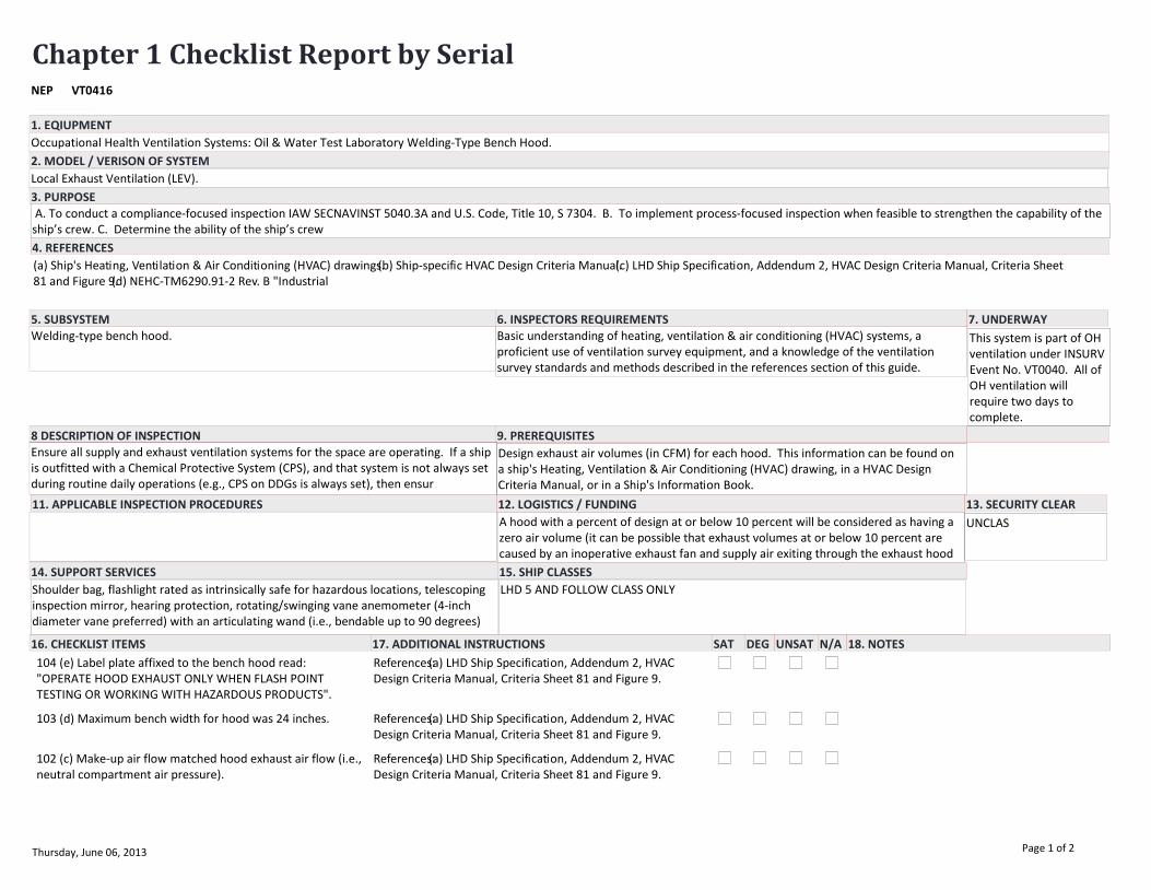
Chapter 1 Checklist Report by SerialVT0416NEP
EQUIPMENT/SYSTEM
Occupational Health Ventilation Systems: Oil & Water Test Laboratory Welding-Type Bench Hood.
(a) Ship's Heating, Ventilation & Air Conditioning (HVAC) drawings.(b) Ship-specific HVAC Design Criteria Manual.(c) LHD Ship Specification, Addendum 2, HVAC Design Criteria Manual, Criteria Sheet 81 and Figure 9.(d) NEHC-TM6290.91-2 Rev. B "Industrial
Welding-type bench hood.
Local Exhaust Ventilation (LEV).
11. APPLICABLE INSPECTION PROCEDURES
3. PURPOSE
5. SUBSYSTEM 6. INSPECTORS REQUIREMENTS
4. REFERENCES
8 DESCRIPTION OF INSPECTION 9. PREREQUISITES
12. LOGISTICS / FUNDING 13. SECURITY CLEAR
14. SUPPORT SERVICES 15. SHIP CLASSES
7. UNDERWAY
2. MODEL / VERISON OF SYSTEM
16. CHECKLIST ITEMS 17. ADDITIONAL INSTRUCTIONS 18. NOTESSAT DEG UNSAT N/A
1. EQIUPMENT
Basic understanding of heating, ventilation & air conditioning (HVAC) systems, a proficient use of ventilation survey equipment, and a knowledge of the ventilation survey standards and methods described in the references section of this guide.
Ensure all supply and exhaust ventilation systems for the space are operating. If a ship is outfitted with a Chemical Protective System (CPS), and that system is not always set during routine daily operations (e.g., CPS on DDGs is always set), then ensur
Design exhaust air volumes (in CFM) for each hood. This information can be found on a ship's Heating, Ventilation & Air Conditioning (HVAC) drawing, in a HVAC Design Criteria Manual, or in a Ship's Information Book.
Shoulder bag, flashlight rated as intrinsically safe for hazardous locations, telescoping inspection mirror, hearing protection, rotating/swinging vane anemometer (4-inch diameter vane preferred) with an articulating wand (i.e., bendable up to 90 degrees)
LHD 5 AND FOLLOW CLASS ONLY
A hood with a percent of design at or below 10 percent will be considered as having a zero air volume (it can be possible that exhaust volumes at or below 10 percent are caused by an inoperative exhaust fan and supply air exiting through the exhaust hood
A. To conduct a compliance-focused inspection IAW SECNAVINST 5040.3A and U.S. Code, Title 10, S 7304. B. To implement process-focused inspection when feasible to strengthen the capability of the ship’s crew. C. Determine the ability of the ship’s crew
UNCLAS
This system is part of OH ventilation under INSURV Event No. VT0040. All of OH ventilation will require two days to complete.
104 (e) Label plate affixed to the bench hood read: "OPERATE HOOD EXHAUST ONLY WHEN FLASH POINT TESTING OR WORKING WITH HAZARDOUS PRODUCTS".
References:(a) LHD Ship Specification, Addendum 2, HVAC Design Criteria Manual, Criteria Sheet 81 and Figure 9.
103 (d) Maximum bench width for hood was 24 inches. References:(a) LHD Ship Specification, Addendum 2, HVAC Design Criteria Manual, Criteria Sheet 81 and Figure 9.
102 (c) Make-up air flow matched hood exhaust air flow (i.e., neutral compartment air pressure).
References:(a) LHD Ship Specification, Addendum 2, HVAC Design Criteria Manual, Criteria Sheet 81 and Figure 9.
Thursday, June 06, 2013 Page 1 of 2
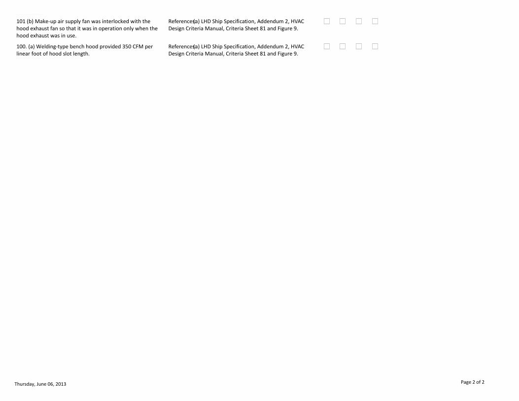
EQUIPMENT/SYSTEM
101 (b) Make-up air supply fan was interlocked with the hood exhaust fan so that it was in operation only when the hood exhaust was in use.
References:(a) LHD Ship Specification, Addendum 2, HVAC Design Criteria Manual, Criteria Sheet 81 and Figure 9.
100. (a) Welding-type bench hood provided 350 CFM per linear foot of hood slot length.
References:(a) LHD Ship Specification, Addendum 2, HVAC Design Criteria Manual, Criteria Sheet 81 and Figure 9.
Thursday, June 06, 2013 Page 2 of 2

Chapter 1 Checklist Report by SerialVT0417NEP
EQUIPMENT/SYSTEM
Occupational Health Ventilation Systems: Oil Test Laboratory Sash Hood.
(a) Ship's Heating, Ventilation & Air Conditioning (HVAC) drawings.(b) Ship-specific HVAC Design Criteria Manual.(c) NAVSEA 0938-LP-018-0010 - HVAC Design Criteria Manual, Criteria Sheet 4A.(d) American Conference of Governmental Industrial Hygienists
Vertical or horizontal sash airfoil hood.
Local Exhaust Ventilation (LEV).
11. APPLICABLE INSPECTION PROCEDURES
3. PURPOSE
5. SUBSYSTEM 6. INSPECTORS REQUIREMENTS
4. REFERENCES
8 DESCRIPTION OF INSPECTION 9. PREREQUISITES
12. LOGISTICS / FUNDING 13. SECURITY CLEAR
14. SUPPORT SERVICES 15. SHIP CLASSES
7. UNDERWAY
2. MODEL / VERISON OF SYSTEM
16. CHECKLIST ITEMS 17. ADDITIONAL INSTRUCTIONS 18. NOTESSAT DEG UNSAT N/A
1. EQIUPMENT
Basic understanding of heating, ventilation & air conditioning (HVAC) systems, a proficient use of ventilation survey equipment, and a knowledge of the ventilation survey standards and methods described in the references section of this guide.
Ensure all supply and exhaust ventilation systems for the space are operating. If a ship is outfitted with a Chemical Protective System (CPS), and that system is not always set during routine daily operations (e.g., CPS on DDGs is always set), then ensur
Design exhaust air volumes (in CFM) for each hood. This information can be found on a ship's Heating, Ventilation & Air Conditioning (HVAC) drawing, in a HVAC Design Criteria Manual, or in a Ship's Information Book.
Shoulder bag, flashlight rated as intrinsically safe for hazardous locations, telescoping inspection mirror, hearing protection, rotating/swinging vane anemometer (4-inch diameter vane preferred) with an articulating wand (i.e., bendable up to 90 degrees)
ALL
A hood with a percent of design at or below 10 percent will be considered as having a zero air volume (it can be possible that exhaust volumes at or below 10 percent are caused by an inoperative exhaust fan and supply air exiting through the exhaust hood
A. To conduct a compliance-focused inspection IAW SECNAVINST 5040.3A and U.S. Code, Title 10, S 7304. B. To implement process-focused inspection when feasible to strengthen the capability of the ship’s crew. C. Determine the ability of the ship’s crew
UNCLAS
This system is part of OH ventilation under INSURV Event No. VT0040. All of OH ventilation will require two days to complete.
104 (e) Hood was installed over test table and chemical sink and was intact.
References:(a) NAVSEA 0938-LP-018-0010 - HVAC Design Criteria Manual, Criteria Sheet 4A.(b) American Conference of Governmental Industrial Hygienists (ACGIH) "Industrial Ventilation - A Manual of Recommended Practice for Design" (26th ed.), Figures VS-
103 (d) Supply ventilation terminal was not located immediately in front of hood.
References:(a) NAVSEA 0938-LP-018-0010 - HVAC Design Criteria Manual, Criteria Sheet 4A.(b) American Conference of Governmental Industrial Hygienists (ACGIH) "Industrial Ventilation - A Manual of Recommended Practice for Design" (26th ed.), Figures VS-
Thursday, June 06, 2013 Page 1 of 2
EQUIPMENT/SYSTEM
102 (c) Equipment inside hood was not located closer than six inches to face of hood.
References:(a) NAVSEA 0938-LP-018-0010 - HVAC Design Criteria Manual, Criteria Sheet 4A.(b) American Conference of Governmental Industrial Hygienists (ACGIH) "Industrial Ventilation - A Manual of Recommended Practice for Design" (26th ed.), Figures VS-
101 (b) Vertical or horizontal sash airfoil hood: If hood sash was supposed to be partially closed for the operation, the hood was so labeled and the appropriate closure point was clearly indicated.
References:(a) NAVSEA 0938-LP-018-0010 - HVAC Design Criteria Manual, Criteria Sheet 4A.(b) American Conference of Governmental Industrial Hygienists (ACGIH) "Industrial Ventilation - A Manual of Recommended Practice for Design" (26th ed.), Figures VS-
100. (a) Vertical or horizontal sash airfoil hood: Had 80-100 FPM full open area face velocity (sash height must be adjusted and marked to 80-100 FPM face velocity if it cannot be achieved with full open face area).
References:(a) NAVSEA 0938-LP-018-0010 - HVAC Design Criteria Manual, Criteria Sheet 4A.(b) American Conference of Governmental Industrial Hygienists (ACGIH) "Industrial Ventilation - A Manual of Recommended Practice for Design" (26th ed.), Figures VS-
Thursday, June 06, 2013 Page 2 of 2
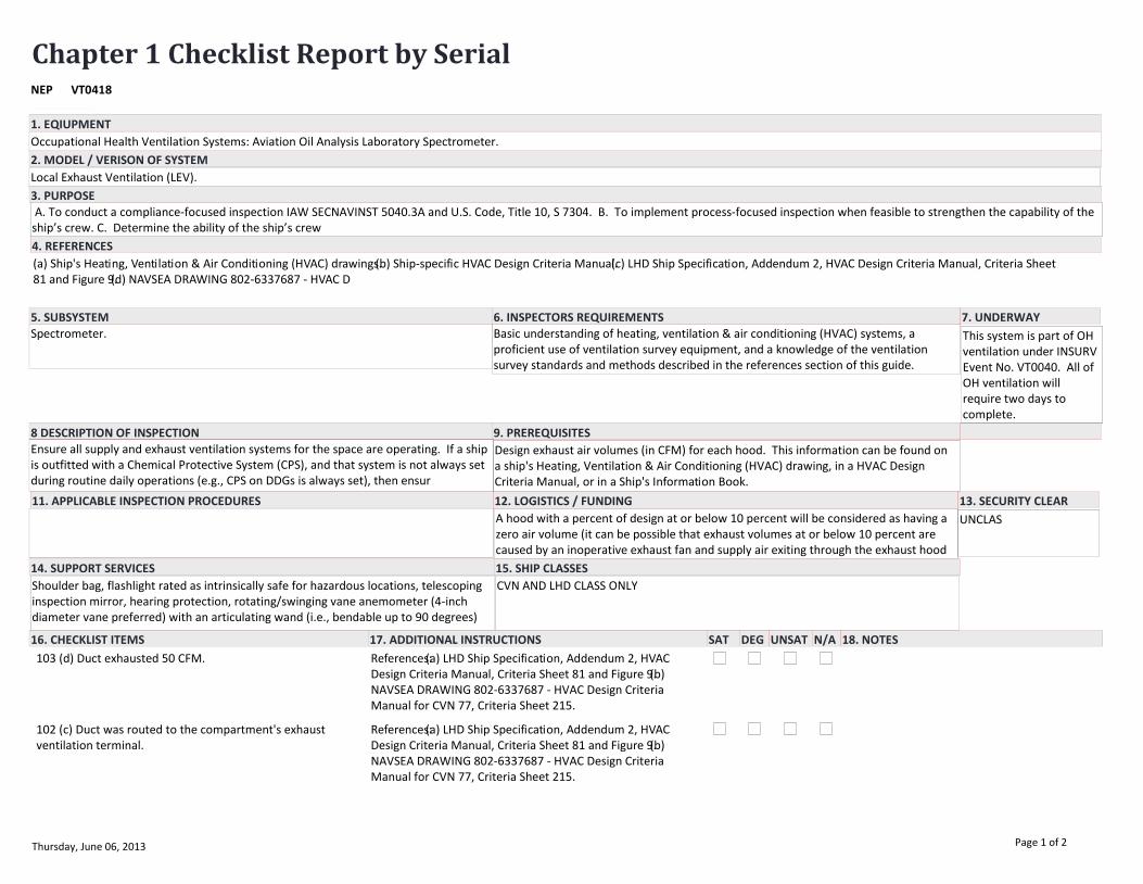
Chapter 1 Checklist Report by SerialVT0418NEP
EQUIPMENT/SYSTEM
Occupational Health Ventilation Systems: Aviation Oil Analysis Laboratory Spectrometer.
(a) Ship's Heating, Ventilation & Air Conditioning (HVAC) drawings.(b) Ship-specific HVAC Design Criteria Manual.(c) LHD Ship Specification, Addendum 2, HVAC Design Criteria Manual, Criteria Sheet 81 and Figure 9.(d) NAVSEA DRAWING 802-6337687 - HVAC D
Spectrometer.
Local Exhaust Ventilation (LEV).
11. APPLICABLE INSPECTION PROCEDURES
3. PURPOSE
5. SUBSYSTEM 6. INSPECTORS REQUIREMENTS
4. REFERENCES
8 DESCRIPTION OF INSPECTION 9. PREREQUISITES
12. LOGISTICS / FUNDING 13. SECURITY CLEAR
14. SUPPORT SERVICES 15. SHIP CLASSES
7. UNDERWAY
2. MODEL / VERISON OF SYSTEM
16. CHECKLIST ITEMS 17. ADDITIONAL INSTRUCTIONS 18. NOTESSAT DEG UNSAT N/A
1. EQIUPMENT
Basic understanding of heating, ventilation & air conditioning (HVAC) systems, a proficient use of ventilation survey equipment, and a knowledge of the ventilation survey standards and methods described in the references section of this guide.
Ensure all supply and exhaust ventilation systems for the space are operating. If a ship is outfitted with a Chemical Protective System (CPS), and that system is not always set during routine daily operations (e.g., CPS on DDGs is always set), then ensur
Design exhaust air volumes (in CFM) for each hood. This information can be found on a ship's Heating, Ventilation & Air Conditioning (HVAC) drawing, in a HVAC Design Criteria Manual, or in a Ship's Information Book.
Shoulder bag, flashlight rated as intrinsically safe for hazardous locations, telescoping inspection mirror, hearing protection, rotating/swinging vane anemometer (4-inch diameter vane preferred) with an articulating wand (i.e., bendable up to 90 degrees)
CVN AND LHD CLASS ONLY
A hood with a percent of design at or below 10 percent will be considered as having a zero air volume (it can be possible that exhaust volumes at or below 10 percent are caused by an inoperative exhaust fan and supply air exiting through the exhaust hood
A. To conduct a compliance-focused inspection IAW SECNAVINST 5040.3A and U.S. Code, Title 10, S 7304. B. To implement process-focused inspection when feasible to strengthen the capability of the ship’s crew. C. Determine the ability of the ship’s crew
UNCLAS
This system is part of OH ventilation under INSURV Event No. VT0040. All of OH ventilation will require two days to complete.
103 (d) Duct exhausted 50 CFM. References:(a) LHD Ship Specification, Addendum 2, HVAC Design Criteria Manual, Criteria Sheet 81 and Figure 9.(b) NAVSEA DRAWING 802-6337687 - HVAC Design Criteria Manual for CVN 77, Criteria Sheet 215.
102 (c) Duct was routed to the compartment's exhaust ventilation terminal.
References:(a) LHD Ship Specification, Addendum 2, HVAC Design Criteria Manual, Criteria Sheet 81 and Figure 9.(b) NAVSEA DRAWING 802-6337687 - HVAC Design Criteria Manual for CVN 77, Criteria Sheet 215.
Thursday, June 06, 2013 Page 1 of 2

EQUIPMENT/SYSTEM
101 (b) Duct was connected to exhaust discharge from Spectrometer with flexible connector,
References:(a) LHD Ship Specification, Addendum 2, HVAC Design Criteria Manual, Criteria Sheet 81 and Figure 9.(b) NAVSEA DRAWING 802-6337687 - HVAC Design Criteria Manual for CVN 77, Criteria Sheet 215.
100. (a) Spectrometer was installed with a four-inch diameter duct.
References:(a) LHD Ship Specification, Addendum 2, HVAC Design Criteria Manual, Criteria Sheet 81 and Figure 9.(b) NAVSEA DRAWING 802-6337687 - HVAC Design Criteria Manual for CVN 77, Criteria Sheet 215.
Thursday, June 06, 2013 Page 2 of 2

Chapter 1 Checklist Report by SerialVT0419NEP
EQUIPMENT/SYSTEM
Occupational Health Ventilation Systems: O2N2 Compartments.
(a) Ship's Heating, Ventilation & Air Conditioning (HVAC) drawings.(b) Ship-specific HVAC Design Criteria Manual.(c) NAVSEA 0938-LP-018-0010 - HVAC Design Criteria Manual, Criteria Sheet 3C.(d) American Conference of Governmental Industrial Hygienists
Exhaust ventilation terminals/ducts (and supply ventilation terminals/ducts for compartments with blowout air systems).
General Exhaust Ventilation (GEV).
11. APPLICABLE INSPECTION PROCEDURES
3. PURPOSE
5. SUBSYSTEM 6. INSPECTORS REQUIREMENTS
4. REFERENCES
8 DESCRIPTION OF INSPECTION 9. PREREQUISITES
12. LOGISTICS / FUNDING 13. SECURITY CLEAR
14. SUPPORT SERVICES 15. SHIP CLASSES
7. UNDERWAY
2. MODEL / VERISON OF SYSTEM
16. CHECKLIST ITEMS 17. ADDITIONAL INSTRUCTIONS 18. NOTESSAT DEG UNSAT N/A
1. EQIUPMENT
Basic understanding of heating, ventilation & air conditioning (HVAC) systems, a proficient use of ventilation survey equipment, and a knowledge of the ventilation survey standards and methods described in the references section of this guide.
Ensure all supply and exhaust ventilation systems for the space are operating. If a ship is outfitted with a Chemical Protective System (CPS), and that system is not always set during routine daily operations (e.g., CPS on DDGs is always set), then ensur
Design exhaust air volumes (in CFM) for each space or hood. This information can be found on a ship's Heating, Ventilation & Air Conditioning (HVAC) drawing, in a HVAC Design Criteria Manual, or in a Ship's Information Book.
Shoulder bag, flashlight, telescoping inspection mirror, hearing protection, rotating/swinging vane anemometer (4-inch diameter vane preferred) with an articulating wand (i.e., bendable up to 90 degrees), thermal (i.e., heated wire/element) anemometer wit
ALL
A space with a percent of design at or below 10 percent will be considered as having a zero air volume (it can be possible that exhaust volumes at or below 10 percent are caused by an inoperative exhaust fan and supply air exiting through the exhaust term
A. To conduct a compliance-focused inspection IAW SECNAVINST 5040.3A and U.S. Code, Title 10, S 7304. B. To implement process-focused inspection when feasible to strengthen the capability of the ship’s crew. C. Determine the ability of the ship’s crew
UNCLAS
This system is part of OH ventilation under INSURV Event No. VT0040. All of OH ventilation will require two days to complete.
105 (f) Supply air was filtered. References:(a) NAVSEA 0938-LP-018-0010 - HVAC Design Criteria Manual, Criteria Sheet 3C.
104 (e) An exhaust terminal was provided no more than nine inches above the deck near the filling bench.
References:(a) NAVSEA 0938-LP-018-0010 - HVAC Design Criteria Manual, Criteria Sheet 3C.NOTE: An approved Departure from Specification (DFS) is required for ships not having an exhaust terminal located no more than nine inches above the deck.
Thursday, June 06, 2013 Page 1 of 2
EQUIPMENT/SYSTEM
103 (d) Mechanical supply ventilation system provided one air change every six minutes (i.e., 10 air changes per hour) in the Fill/Producer/Refrigeration/Stowage Rooms on or above the weather decks.
References:(a) NAVSEA 0938-LP-018-0010 - HVAC Design Criteria Manual, Criteria Sheet 3C.
102 (c) Mechanical supply ventilation system provided one air change every one minute (i.e., 60 air changes per hour) in Fill/Producer/Refrigeration/Stowage Rooms below the weather decks.
References:(a) NAVSEA 0938-LP-018-0010 - HVAC Design Criteria Manual, Criteria Sheet 3C.
101 (b) Mechanical exhaust ventilation system provided one air change every one minute (i.e., 60 air changes per hour) in the O2N2 Compressor Room.
References:(a) NAVSEA 0938-LP-018-0010 - HVAC Design Criteria Manual, Criteria Sheet 3C.
100. (a) Mechanical ventilation system had measured airflow per design criteria.
References:(a) NAVSEA 0938-LP-018-0010 - HVAC Design Criteria Manual, Criteria Sheet 3C.
Thursday, June 06, 2013 Page 2 of 2

Chapter 1 Checklist Report by SerialVT0420NEP
EQUIPMENT/SYSTEM
Occupational Health Ventilation Systems: Paint Mixing & Issue Room.
(a) Ship's Heating, Ventilation & Air Conditioning (HVAC) drawings.(b) Ship-specific HVAC Design Criteria Manual.(c) NAVSEA 0938-LP-018-0010 - HVAC Design Criteria Manual, Criteria Sheet 13A.(d) NAVSEA DWG NO: 802-5959327, HVAC Design Criteria Manual,
Exhaust ventilation terminals/ducts.
General Exhaust Ventilation (GEV).
11. APPLICABLE INSPECTION PROCEDURES
3. PURPOSE
5. SUBSYSTEM 6. INSPECTORS REQUIREMENTS
4. REFERENCES
8 DESCRIPTION OF INSPECTION 9. PREREQUISITES
12. LOGISTICS / FUNDING 13. SECURITY CLEAR
14. SUPPORT SERVICES 15. SHIP CLASSES
7. UNDERWAY
2. MODEL / VERISON OF SYSTEM
16. CHECKLIST ITEMS 17. ADDITIONAL INSTRUCTIONS 18. NOTESSAT DEG UNSAT N/A
1. EQIUPMENT
Basic understanding of heating, ventilation & air conditioning (HVAC) systems, a proficient use of ventilation survey equipment, and a knowledge of the ventilation survey standards and methods described in the references section of this guide.
Ensure all supply and exhaust ventilation systems for the space are operating. If a ship is outfitted with a Chemical Protective System (CPS), and that system is not always set during routine daily operations (e.g., CPS on DDGs is always set), then ensur
Design exhaust air volumes (in CFM) for each space or hood. This information can be found on a ship's Heating, Ventilation & Air Conditioning (HVAC) drawing, in a HVAC Design Criteria Manual, or in a Ship's Information Book.
Shoulder bag, flashlight rated as intrinsically safe for hazardous locations, telescoping inspection mirror, hearing protection, rotating/swinging vane anemometer (4-inch diameter vane preferred) with an articulating wand (i.e., bendable up to 90 degrees)
ALL
A space with a percent of design at or below 10 percent will be considered as having a zero air volume (it can be possible that exhaust volumes at or below 10 percent are caused by an inoperative exhaust fan and supply air exiting through the exhaust term
A. To conduct a compliance-focused inspection IAW SECNAVINST 5040.3A and U.S. Code, Title 10, S 7304. B. To implement process-focused inspection when feasible to strengthen the capability of the ship’s crew. C. Determine the ability of the ship’s crew
UNCLAS
This system is part of OH ventilation under INSURV Event No. VT0040. All of OH ventilation will require two days to complete.
107 (h) An exhaust terminal was installed in the overhead. References:(a) NAVSEA 0938-LP-018-0010 - HVAC Design Criteria Manual, Criteria Sheet 13A.(b) NAVSEA DWG NO: 802-5959327, HVAC Design Criteria Manual, pp. 18-65 & 18-65A (DDG 51 Class).(c) LPD-17 Ship Specification, Addendum 2, HVAC Design Criteria Manu
106 (g) Exhaust terminals were no more than nine inches above the deck.
References:(a) NAVSEA 0938-LP-018-0010 - HVAC Design Criteria Manual, Criteria Sheet 13A.(b) NAVSEA DWG NO: 802-5959327, HVAC Design Criteria Manual, pp. 18-65 & 18-65A (DDG 51 Class).(c) LHD Ship Specification, Addendum 2, HVAC Design Criteria Manual,
Thursday, June 06, 2013 Page 1 of 2

EQUIPMENT/SYSTEM
105 (f) Exhaust terminal screens were fitted with a quick disconnect from the vent terminal and secured by a 1/16-inch diameter, 7- by 7- wire rope lanyard of compatible material, at least 7 inches in length.
References:(a) GSO 2004, Section 512e.
104 (e) Exhaust terminal had 1-1/2 inch mesh (0.120 inch diameter wire) screens. For openings nine inches in diameter or less, or where the small dimension of a rectangular opening is nine inches or less, 1/2 inch mesh (0.063 inch diameter wire for inter
References:(a) GSO 2004, Section 512e.(b) NSTM 510, 510-7.1.9.NOTE: Expanded metal, perforated metal, and other non-wire mesh screens are not authorized.
103 (d) Supply terminals had eight-mesh (0.035 inch diameter wire) screens.
References:(a) NAVSEA 0938-LP-018-0010 - HVAC Design Criteria Manual, Criteria Sheet 13A.(b) NAVSEA DWG NO: 802-5959327, HVAC Design Criteria Manual, pp. 18-65 & 18-65A (DDG 51 Class).(c) NSTM 510, 510-7.1.9.NOTE: Expanded metal, perforated metal, an
102 (c) Minimum negative air pressure (-0.25 inches of water pressure) was maintained when access doors were closed.
References:(a) NAVSEA 0938-LP-018-0010 - HVAC Design Criteria Manual, Criteria Sheet 13A.(b) NAVSEA DWG NO: 802-5959327, HVAC Design Criteria Manual, pp. 18-65 & 18-65A (DDG 51 Class).(c) LHD Ship Specification, Addendum 2, HVAC Design Criteria Manual,
101 (b) Mechanical exhaust ventilation system provided one air change every four minutes (i.e., 15 air changes per hour).
References:(a) NAVSEA 0938-LP-018-0010 - HVAC Design Criteria Manual, Criteria Sheet 13A.(b) NAVSEA DWG NO: 802-5959327, HVAC Design Criteria Manual, pp. 18-65 & 18-65A (DDG 51 Class).(c) LHD Ship Specification, Addendum 2, HVAC Design Criteria Manual,
100. (a) Mechanical ventilation system had measured airflow per design criteria.
References:(a) NAVSEA 0938-LP-018-0010 - HVAC Design Criteria Manual, Criteria Sheet 13A.(b) NAVSEA DWG NO: 802-5959327, HVAC Design Criteria Manual, pp. 18-65 & 18-65A (DDG 51 Class).(c) LHD Ship Specification, Addendum 2, HVAC Design Criteria Manual,
Thursday, June 06, 2013 Page 2 of 2
Chapter 1 Checklist Report by SerialVT0421NEP
EQUIPMENT/SYSTEM
Occupational Health Ventilation Systems: Terminal.
(a) Ship's Heating, Ventilation & Air Conditioning (HVAC) drawings.(b) Ship-specific HVAC Design Criteria Manual.(c) MIP 6641, A-18.(d) NAVSEA 0938-LP-018-0010 - HVAC Design Criteria Manual.(e) GSO 2004, Section 512e.(f) NSTM 510, 510-7.1.9.(g) Amer
Supply and exhaust ventilation terminals.
General Supply and Exhaust Ventilation.
11. APPLICABLE INSPECTION PROCEDURES
3. PURPOSE
5. SUBSYSTEM 6. INSPECTORS REQUIREMENTS
4. REFERENCES
8 DESCRIPTION OF INSPECTION 9. PREREQUISITES
12. LOGISTICS / FUNDING 13. SECURITY CLEAR
14. SUPPORT SERVICES 15. SHIP CLASSES
7. UNDERWAY
2. MODEL / VERISON OF SYSTEM
16. CHECKLIST ITEMS 17. ADDITIONAL INSTRUCTIONS 18. NOTESSAT DEG UNSAT N/A
1. EQIUPMENT
Basic understanding of heating, ventilation & air conditioning (HVAC) systems; and, a knowledge of the ventilation survey standards and methods described in the references section of this guide.
Shoulder bag, flashlight rated as intrinsically safe for hazardous locations, telescoping inspection mirror, hearing protection, and self-retracting tape measure.
ALL
If a ventilation terminal did not meet specifications, it is a Priority 2 deficiency for the space with an EOC score of up to 0.9. Water that is dripping, splashing, or being blown onto electric or electronic equipment is a Priority 1 Safety deficiency w
A. To conduct a compliance-focused inspection IAW SECNAVINST 5040.3A and U.S. Code, Title 10, S 7304. B. To implement process-focused inspection when feasible to strengthen the capability of the ship’s crew. C. Determine the ability of the ship’s crew
UNCLAS
This system is part of OH ventilation under INSURV Event No. VT0040. All of OH ventilation will require two days to complete.
105 (f) Terminal was arranged to prevent water from dripping, splashing, or being blown onto electric or electronic equipment; prevent disturbing the capture range of hoods made especially for the equipment; prevent short circuiting of air between supply
References:(a) GSO 2004, Section 512e.Scoring: Water that is dripping, splashing, or being blown onto electric or electronic equipment is a Priority 1 Safety deficiency with a maximum EOC score of up to 0.2.
104 (e) Exhaust terminal screens were fitted with a quick disconnect from the vent terminal and secured by a 1/16-inch diameter, 7- by 7- wire rope lanyard of compatible material, at least seven inches in length.
References:(a) GSO 2004, Section 512e.
Thursday, June 06, 2013 Page 1 of 2

EQUIPMENT/SYSTEM
103 (d) Ventilation terminals were clean and unclogged. References:(a) MIP 6641, A-18.(b) GSO 2004, Section 512e.(c) NSTM 510, 510-7.1.9.
102 (c) Ventilation diffusers were not damaged or missing. References:(a) MIP 6641, A-18.(b) GSO 2004, Section 512e.(c) NSTM 510, 510-7.1.9.
101 (b) Exhaust terminals had 1-1/2 inch mesh (0.120 inch diameter wire) screens. For openings nine inches in diameter or less, or where the small dimension of a rectangular opening is nine inches or less, 1/2 inch mesh (0.063 inch diameter wire for inte
References:(a) GSO 2004, Section 512e.(b) NSTM 510, 510-7.1.9.NOTE: Expanded metal, perforated metal, and other non-wire mesh screens are not authorized.
100. (a) Exhaust ventilation terminal mesh screens were present.
References:(a) MIP 6641, A-18.(b) NAVSEA 0938-LP-018-0010 - HVAC Design Criteria Manual.(c) GSO 2004, Section 512e.(d) NSTM 510, 510-7.1.9.NOTE: Expanded metal, perforated metal, and other non-wire mesh screens are not authorized.
Thursday, June 06, 2013 Page 2 of 2
Chapter 1 Checklist Report by SerialVT0422NEP
EQUIPMENT/SYSTEM
Occupational Health Ventilation Systems: Flexible Welding Exhaust Hood.
(a) Ship's Heating, Ventilation & Air Conditioning (HVAC) drawings.(b) Ship-specific HVAC Design Criteria Manual.(a) Ship's Heating, Ventilation & Air Conditioning (HVAC) drawings.(b) Ship-specific HVAC Design Criteria Manual.(c) NAVSEA 0938-LP-018-00
Flexible Welding Exhaust Hood.
Local Exhaust Ventilation (LEV).
11. APPLICABLE INSPECTION PROCEDURES
3. PURPOSE
5. SUBSYSTEM 6. INSPECTORS REQUIREMENTS
4. REFERENCES
8 DESCRIPTION OF INSPECTION 9. PREREQUISITES
12. LOGISTICS / FUNDING 13. SECURITY CLEAR
14. SUPPORT SERVICES 15. SHIP CLASSES
7. UNDERWAY
2. MODEL / VERISON OF SYSTEM
16. CHECKLIST ITEMS 17. ADDITIONAL INSTRUCTIONS 18. NOTESSAT DEG UNSAT N/A
1. EQIUPMENT
Basic understanding of heating, ventilation & air conditioning (HVAC) systems, a proficient use of ventilation survey equipment, and a knowledge of the ventilation survey standards and methods described in the references section of this guide.
Ensure all supply and exhaust ventilation systems for the space are operating. If a ship is outfitted with a Chemical Protective System (CPS), and that system is not always set during routine daily operations (e.g., CPS on DDGs is always set), then ensur
Design exhaust air volumes (in CFM) for each hood. This information can be found on a ship's Heating, Ventilation & Air Conditioning (HVAC) drawing, in a HVAC Design Criteria Manual, or in a Ship's Information Book.
Shoulder bag, flashlight, telescoping inspection mirror, hearing protection, rotating/swinging vane anemometer (4-inch diameter vane preferred) with an articulating wand (i.e., bendable up to 90 degrees), thermal (i.e., heated wire/element) anemometer wit
ALL
A hood with a percent of design at or below 10 percent will be considered as having a zero air volume (it can be possible that exhaust volumes at or below 10 percent are caused by an inoperative exhaust fan and supply air exiting through the exhaust hood
A. To conduct a compliance-focused inspection IAW SECNAVINST 5040.3A and U.S. Code, Title 10, S 7304. B. To implement process-focused inspection when feasible to strengthen the capability of the ship’s crew. C. Determine the ability of the ship’s crew
UNCLAS
This system is part of OH ventilation under INSURV Event No. VT0040. All of OH ventilation will require two days to complete.
106 (g) Hood was able to reach entire work surface. References:(a) NAVSEA 0938-LP-018-0010 - HVAC Design Criteria Manual, Criteria Sheets 4A (3.12) and 4D (3.1), and Figure 4A.(b) NAVSEA DWG 802-5959327, Revision BD, HVAC Design Criteria Manual, Criteria Sheet 18-57 and Figure 18-6 (DDG 51 Class).(c) LP
105 (f) Hood had a clean screen. [Only CVN 71 and later of the CVN 68 Class; CG 47, DDG 51, DDG 993, LHD 1, LPD 17, FFG 7, MHC 51, and PC 1 Classes]
References:(a) MIP 6641/005, A-18.
Thursday, June 06, 2013 Page 1 of 2
EQUIPMENT/SYSTEM
104 (e) Label plate was installed on face of hood with the following instructions: "LOCATE OPENING OF THIS HOOD WITHIN 7-1/2 INCHES OF WORKING POINT."
References:(a) NAVSEA 0938-LP-018-0010 - HVAC Design Criteria Manual, Criteria Sheets 4A (3.12) and 4D (3.1), and Figure 4A.
103 (d) Label plate was installed on face of hood with the following instructions: "OPERATE EXHAUST SYSTEM AND COMPANION SUPPLY SYSTEM AT HIGH SPEED WHILE USING THIS HOOD."
References:(a) NAVSEA 0938-LP-018-0010 - HVAC Design Criteria Manual, Criteria Sheets 4A (3.12) and 4D (3.1), and Figure 4A.
102 (c) Flexible hose had a six-inch inner diameter. References:(a) NAVSEA 0938-LP-018-0010 - HVAC Design Criteria Manual, Criteria Sheets 4A (3.12) and 4D (3.1), and Figure 4A.
101 (b) Hood face volume measured at least 300 CFM. References:(a) NAVSEA 0938-LP-018-0010 - HVAC Design Criteria Manual, Criteria Sheets 4A (3.12) and 4D (3.1), and Figure 4A.(b) NAVSEA DWG 802-5959327, Revision BD, HVAC Design Criteria Manual, Criteria Sheet 18-57 and Figure 18-6 (DDG 51 Class).(c) LP
100. (a) Welding slab area had a mechanical exhaust hood installed per Figure 4A of Criteria Sheets 4A or 4D.
References:(a) NAVSEA 0938-LP-018-0010 - HVAC Design Criteria Manual, Criteria Sheets 4A (3.12) and 4D (3.1), and Figure 4A.(b) NAVSEA DWG 802-5959327, Revision BD, HVAC Design Criteria Manual, Criteria Sheet 18-57 and Figure 18-6 (DDG 51 Class).(c) LP
Thursday, June 06, 2013 Page 2 of 2