Embed Size (px)
Citation preview

Chapter 1
F U N D A M E N T A L A S P E C T S OF C A S I N G D E S I G N
1.1 P U R P O S E OF C A S I N G
At a certain stage during the drilling of oil and gas wells, it becomes necessary to line the walls of a borehole with steel pipe which is called casing. Casing serves numerous purposes during the drilling and production history of oil and gas wells, these include:
1. Keeping the hole open by preventing the weak formations from collapsing, i.e., caving of the hole.
2. Serving as a high strength flow conduit to surface for both drilling and production fluids.
3. Protecting the freshwater-bearing formations from contamination by drilling and production fluids.
4. Providing a suitable support for wellhead equipment and blowout preventers for controlling subsurface pressure, and for the installation of tubing and subsurface equipment.
5. Providing safe passage for running wireline equipment.
6. Allowing isolated comnmnication with selectively perforated formation(s) of interest.
1.2 T Y P E S OF C A S I N G
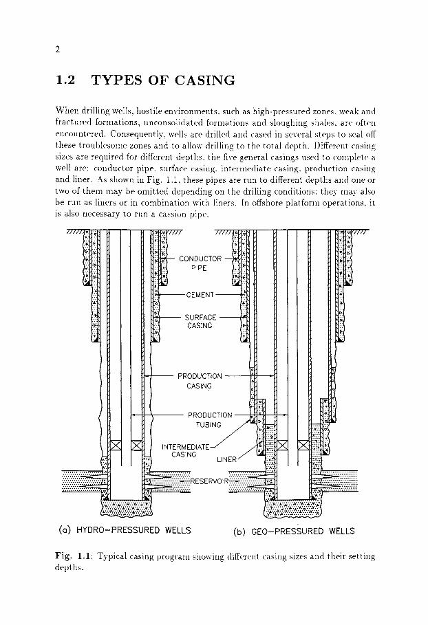
When drilling wells, hostile environments, such as high-pressured zones, weak and fractured formations, unconsolidated forinations and sloughing shales, are often encountered. Consequently, wells are drilled and cased in several steps to seal off these troublesome zones and to allow drilling to the total depth. Different casing sizes are required for different depths, the five general casings used to complete a well are: conductor pipe, surface casing, intermediate casing, production casing and liner. As shown in Fig. 1.1, these pipes are run to different depths and one or two of them may be omitted depending on the drilling conditions: they may also be run as liners or in combination with liners. In offshore platform operations, it is also necessary to run a cassion pipe.
/////t::~:~
ii . .
. .
. ,
Z .
. .
.7 . .
g ,
. .
.
. . + al
c0 00c,o -
--,-----.-..----CEMENT
SURFACE CASING
PRODUCTION
CASING
PRODUCTION
TUBING
i.i~" l'!f l l l l
2.i
..
r
INTERMEDIATE CASING
LINER
iiiiiiiii:i i . . . . . . . . . . .
. . . . . . . . . : . : . : . : . : . : . : . : . : . . . . . . . . . ~ : : - : : : : : : : : : : : : : :
: ': ':-:~R ES E RVOIR~Z-:'Z'Z':-.v.'.'. ............... %~176176176 ~ o . . . . . . .~176176176 ~ 1 7 6
�9 " ~ . " : : . . . . . . . . v : . v : . ' ~ ~ ........ �9 ~ , . ' . , . o . ' . ' . ' . ' . ' . ' . ' . ' . . . . . . . . . . . . v . v . " . v . ' Z " Z " "... . ' . ' . ' . ' . ' . ' . ' . ' . ' . ' . ' . ' . ' ."
(O) HYDRO-PRESSURED WELLS (b) GEO-PRESSURED WELLS
Fig. 1.1" Typical casing program showing different casing sizes and their setting depths.
1.2.1 Cassion Pipe
On an offshore platform, a cassion pipe, usually' 26 to 42 in. in outside diameter (OD), is driven into the sea bed to prevent washouts of near-surface unconsoli- dated formations and to ensure the stability of the ground surface upon which the rig is seated. It also serves as a flow conduit for drilling fluid to the surface. The cassion pipe is tied back to the conductor or surface casing and usually does not carry any load.
1.2.2 Conductor Pipe
The outermost casing string is the conductor pipe. The main purpose of this casing is to hold back the unconsolidated surface formations and prevent them from falling into the hole. The conductor pipe is cemented back to the surface and it is either used to support subsequent casings and wellhead equipment or the pipe is cut off at the surface after setting the surface casing. Where shallow water or gas flow is expected, the conductor pipe is fitted with a diverter system above the flowline outlet. This device permits the diversion of drilling fluid or gas flow away from the rig in the event of a surface blowout. The conductor pipe is not shut-in in the event of fluid or gas flow, because it is not set in deep enough to provide any holding force.
The conductor pipe, which varies in length from 40 to 500 ft onshore and up to 1,000 ft offshore, is 7 to 20 in. in diameter. Generally. a 16-in. pipe is used in shallow wells and a 20-in. in deep wells. On offshore platforms, conductor pipe is usually 20 in. in diameter and is cemented across its entire length.
1.2.3 Surface Casing
The principal functions of the surface casing string are to: hold back unconsoli- dated shallow formations that can slough into the hole and cause problems, isolate the freshwater-bearing formations and prevent their contamination by fluids from deeper formations and to serve as a base on which to set the blowout preventers. It is generally set in competent rocks, such as hard limestone or dolomite, so that it can hold any pressure that may be encountered between the surface casing seat and the next casing seat.
Setting depths of the surface casing vary from a few hundred feet to as nmch as 5,000 ft. Sizes of the surface casing vary from 7 to 16 in. in diameter, with
a in. and l ' a 10 a 3g in. being the most common sizes. On land. surface casing is usually cemented to the surface. For offshore wells, the cement column is frequently limited to the kickoff point.
1.2.4 Intermediate Casing
Intermediate or protective casing is set at a depth between the surface and pro- duction casings. The main reason for setting intermediate casing is to case off the formations that prevent the well from being drilled to the total depth. Trou- blesome zones encountered include those with abnormal formation pressures, lost circulation, unstable shales and salt sections. When abnormal formation pressures are present in a deep section of the well. intermediate casing is set to protect for- mations below the surface casing from the pressures created by the drilling fluid specific weight required to balance the abnormal pore pressure. Similarly, when normal pore pressures are found below sections having abnormal pore pressure, an additional intermediate casing may be set to allow for the use of more eco- nonfical, lower specific weight, drilling fluids in the subsequent sections. After a troublesome lost circulation, unstable shale or salt section is penetrated, in- termediate casing is required to prevent well problems while drilling below these sections.
Intermediate casing varies in length from 7.000 ft to as nmch as 15.000 ft and from 7 in. to 1 l a3 in. in outside diameter. It is commonlv~ cemented up to 1,000 ft from the casing shoe and hung onto the surface casing. Longer cement columns are sometimes necessary to prevent casing buckling.
1.2.5 Product ion Casing
Production casing is set through the prospective productive zones except in the case of open-hole completions. It is usually designed to hold the maximal shut-in pressure of the producing formations and may be designed to withstand stim- ulating pressures during completion and workover operations. It also provides protection for the environment in the event of failure of the tubing string during production operations and allows for the production tubing to be repaired and replaced.
1 in . t o 9 5 Production casing varies from 4 5 ~ in. in diameter, and is cemented far enough above the producing formations to provide additional support for subsurface equipment and to prevent casing buckling.
1.2.6 Liners
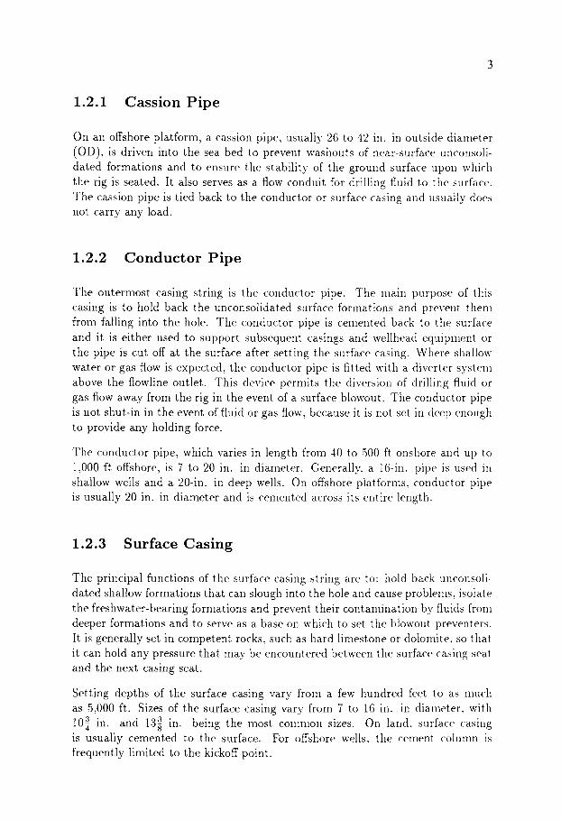
Liners are the pipes that do not usually reach the surface, but are suspended from the bottom of the next largest casing string. Usually, they are set to seal off troublesome sections of the well or through the producing zones for economic reasons. Basic liner assemblies currently in use are shown in Fig. 1.2, these
include: drilling liner, production liner, tie-back liner, scab liner, and scab tie- back liner (Brown- Hughes Co., 1984).
TIE BACK
SCAB LINER
SCAB TIE BACK LINER
(a) LINER (b) TIE BACK LINER (c) SCAB LINER (d) SCAB-TIE BACK LINER
Fig. 1.2: Basic liner system. (After Brown- Hughes Co., 1984.)
Drilling liner: Drilling liner is a section of casing that is suspended from the existing casing (surface or intermediate casing). In most cases, it extends downward into the openhole and overlaps the existing casing by 200 to 400 ft. It is used to isolate abnormal formation pressure, lost circulation zones, heaving shales and salt sections, and to permit drilling below these zones without having well problems.
P r o d u c t i o n liner: Production liner is run instead of full casing to provide isolation across the production or injection zones. In this case, intermediate casing or drilling liner becomes part of the completion string.
T ie -back liner" Tie-back liner is a section of casing extending upwards from the top of the existing liner to the surface. This pipe is connected to the top of the liner (Fig. 1.2(b)) with a specially designed connector. Production liner with tie-back liner assembly is most advantageous when exploratory drilling below the productive interval is planned. It also gives rise to low hanging-weights in the upper part of the well.
Scab liner: Scab liner is a section of casing used to repair existing damaged casing. It may be cemented or sealed with packers at the top and bottom (Fig. :.2(c)).
Scab t ie -back liner: This is a section of casing extending upwards from the ex- isting liner, but which does not reach the surface and is normally cemented in place. Scab tie-back liners are commonly used with cemented heavy-wall casing to isolate salt sections in deeper portions of the well.
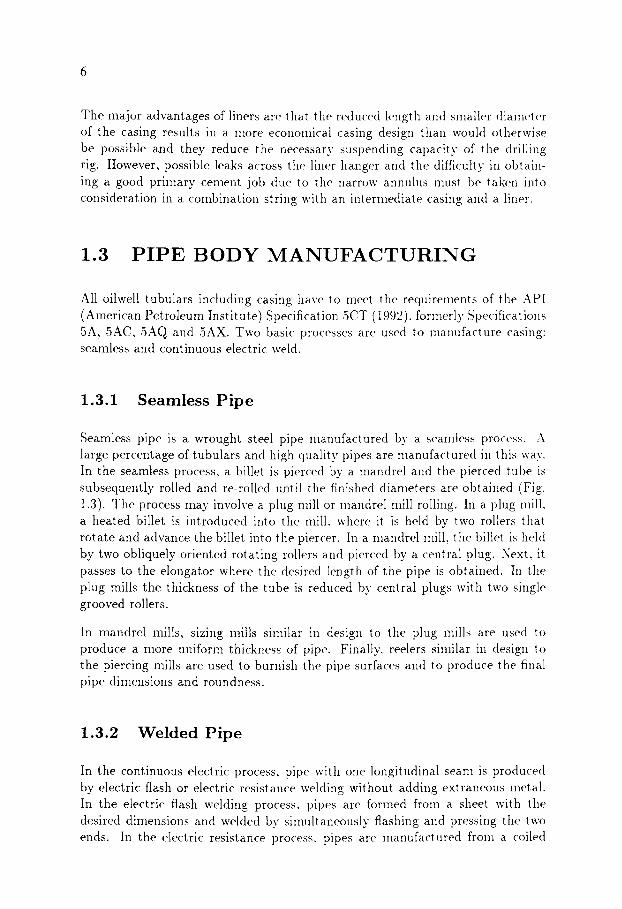
The major advantages of liners are that the reduced length and smaller diameter of the casing results in a more economical casing design than would otherwise be possible and they reduce the necessary suspending capacity of the drilling rig. However, possible leaks across the liner hanger and the difficult)" in obtain- ing a good primary cement job due to the narrow annulus nmst be taken into consideration in a combination string with an intermediate casing and a liner.
1.3 P I P E B O D Y M A N U F A C T U R I N G
All oilwell tubulars including casing have to meet the requirements of the API (American Petroleum Institute) Specification 5CT (1992), forlnerly Specifications 5A, 5AC, 5AQ and 5AX. Two basic processes are used to manufacture casing: seamless and continuous electric weld.
1.3.1 Seamless Pipe
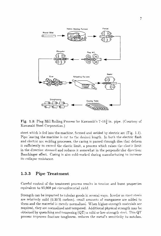
Seamless pipe is a wrought steel pipe manufactured by a seamless process. A large percentage of tubulars and high quality pipes are manufactured in this way. In the seamless process, a billet is pierced by a inandrel and the pierced tube is subsequently rolled and re-rolled until the finished diameters are obtained (Fig. 1.3). The process may involve a plug mill or mandrel mill rolling. I1: a plug nfill, a heated billet is introduced into the mill. where it is held by two rollers that rotate and advance the billet into the piercer. In a mandrel mill, the billet is held by two obliquely oriented rotating rollers and pierced by a central plug. Next, it passes to the elongator where the desired length of the pipe is obtained. In the plug mills the thickness of the tube is reduced by central plugs with two single grooved rollers.
In mandrel mills, sizing mills similar in design to the plug mills are used to produce a more uniform thickness of pipe. Finally, reelers siInilar in design to the piercing mills are used to burnish the pipe surfaces and to produce the final pipe dimensions and roundness.
1.3.2 Welded Pipe
In the continuous electric process, pipe with one longitudinal seam is produced by electric flash or electric resistance welding without adding extraneous metal. In the electric flash welding process, pipes are formed from a sheet with the desired dimensions and welded by sinmltaneously flashing and pressing the two ends. In the electric resistance process, pipes are inanufactured from a coiled
Round Billet Rotor), Heoting Furnoce Piercer
.@ Elongotor Plug Mill
Reeler Sizer Re_heoting Furnoce ( ~ ~
3 in. pipe. (Courtesy of Fig. 1.3" Plug Mill Rolling Process for Kawasaki's 7-16g Kawasaki Steel Corporation.)
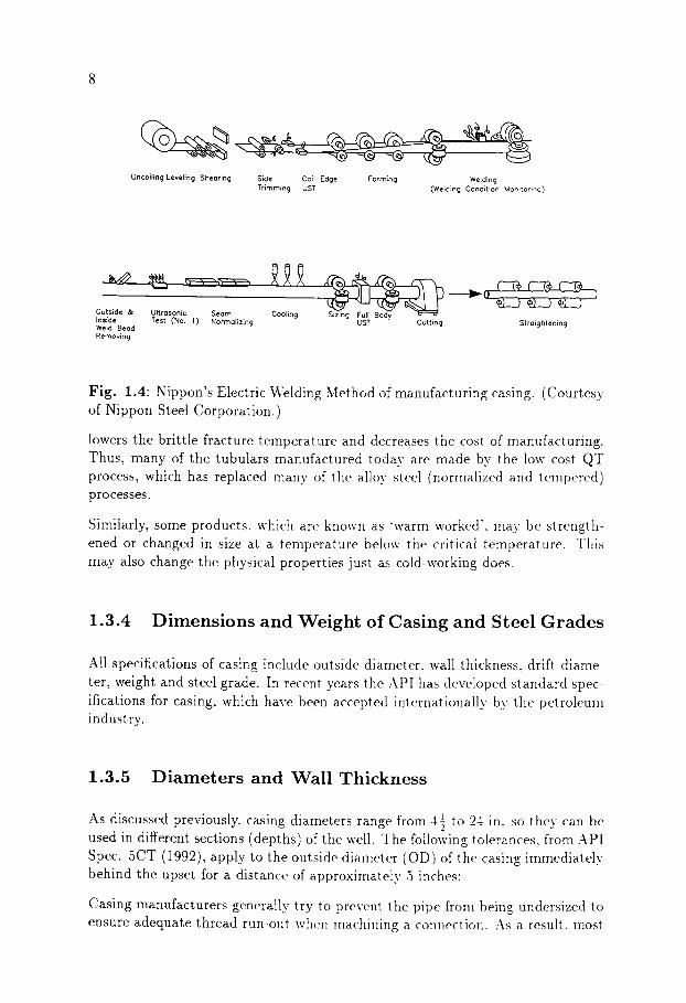
sheet which is fed into the machine, formed and welded by" electric arc (Fig. 1.4). Pipe leaving the machine is cut to the desired length. In both the electric flash and electric arc welding processes, the casing is passed through dies that deform it sufficiently to exceed the elastic limit, a process which raises the elastic limit in the direction stressed and reduces it somewhat in the perpendicular direction" Bauchinger effect. Casing is also cold-worked during manufacturing to increase its collapse resistance.
1.3.3 P ipe Treatment
Careful control of the treatment process results in tension and burst properties equivalent to 95,000 psi circumferential yield.
Strength can be imparted to tubular goods in several ways. Insofar as most steels are relatively mild (0.,30 % carbon), small amounts of manganese are added to them and the material is merely normalized. When higher-strength materials are required, they are normalized and tempered. Additional physical strength may be obtained by quenching and tempering (QT) a mild or low-strength steel. This QT process improves fracture toughness, reduces the metal's sensitivity to notches,
Uncoiling Leveling Shearing Side Coil Edge Forming Welding Trimming UST (Welding Condition Monitoring)
Outside & Ultrasonic Seam Inside Test (No. 1) Normalizing Weld Bead Removing
Cooling UST Cutting Straightening
Fig. 1.4" Nippon's Electric Welding Method of manufacturing casing. (Courtesy of Nippon Steel Corporation.)
lowers the brittle fracture temperature and decreases the cost of manufacturing. Thus, many of the tubulars manufactured today are made by the low cost QT process, which has replaced many of the alloy steel (normalized and tempered) processes.
Similarly, some products, which are known as "warm worked', may be strength- ened or changed in size at a temperature below the critical temperature. This may also change the physical properties just as cold-working does.
1.3.4 Dimens ions and Weight of Casing and Steel Grades
All specifications of casing include outside diameter, wall thickness, drift diame- ter, weight and steel grade. In recent years the API has developed standard spec- ifications for casing, which have been accepted internationally by the petroleum industry.
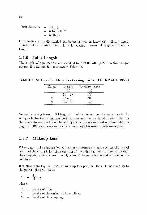
1.3.5 Diameters and Wall Thickness
1 2 4 . . As discussed previously, casing diameters range from 4 5 to in so t hev can be used in different sections (depths) of the well. The following tolerances, from API Spec. 5CT (1992), apply to the outside diameter (OD) of the casing immediately behind the upset for a distance of approximately 5 inches:
Casing manufacturers generally try to prevent the pipe from being undersized to ensure adequate thread run-out when machining a connection. As a result, most
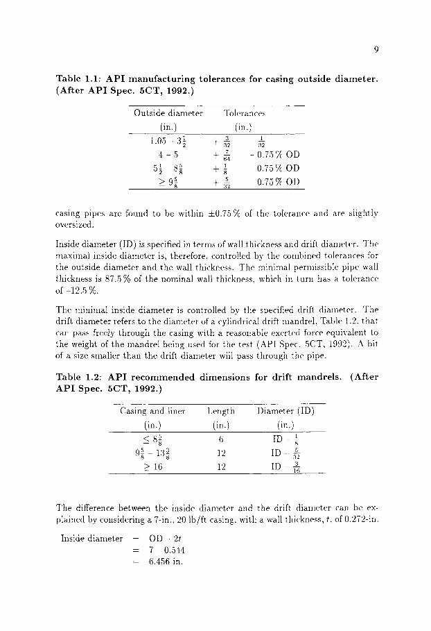
Table 1.1" A P I m a n u f a c t u r i n g to l e rances for cas ing ou t s ide d i a m e t e r . (Af te r A P I Spec. 5CT , 1992.)
Outside diameter Tolerances
(in.) (in.) 1 3
1 0 5 - 3 7 q " 32
"7 4 - 5 q - ~ 1 5 1 5 ~ - 8g t s
5 5 ~ 9 g } 32
1
32
0.75 ~ OD
0.75 ~2~ OD
0.75 ~ OD
casing pipes are found to be within -1-0.75 % of the tolerance and are slightly oversized.
Inside diameter (ID) is specified in terms of wall thickness and drift diameter. The maximal inside diameter is, therefore, controlled by the combined tolerances for the outside diameter and the wall thickness. The minimal permissible pipe wall thickness is 87.5 % of the nominal wall thickness, which in turn has a tolerance of-12.5 %.
The minimal inside diameter is controlled by the specified drift diameter. The drift diameter refers to the diameter of a cylindrical drift mandrel, Table 1.2, that can pass freely through the casing with a reasonable exerted force equivalent to the weight of the mandrel being used for the test (API Spec. 5CT, 1992). A bit of a size smaller than the drift, diameter will pass through the pipe.
Table 1.2: A P I r e c o m m e n d e d d i m e n s i o n s for dr i f t m a n d r e l s . A P I Spec. 5CT, 1992.)
(Af te r
Casing and liner Length Diameter (ID)
(in.) (in.) (in.) 5 1 G 8~ 6 ID 8
5 3 12 ID 5 9g - 13g .32 > 16 12 ID 3
16
The difference between the inside diaineter and the drift diameter can be ex- plained by considering a 7-in., 20 lb/ft casing, with a wall thickness, t, of 0.272-in.
Inside diameter - O D - 2t - 7 - 0.544 = 6.4,56 in.
m
m
m
o~.
cm
o~.
m-m-to-
o
o
�9
m- m- .-.
<3
m
m
~_..
o
co.
�9
o ~'
J ~
.~"
~ ~ b,
~
~ e~
�9
�9
e..
*
o
F~
'~
~ 1;
:I r~
~
~"
,~"
~ E
~
~~
-
i-.,-,
i.-
.,.
i-a
~-'
o
,.o
�9
.,1)
,--.--
' 0
~ ,.o
�9
--"
m"
0
"-"
H.
~
m
~2
. O
~ "
~
o ~
m
__.
~.
~,
~
m
~ 2L
, ~
~ --
. ~
r '
~
~ ~
'~
--.~
ee
~.
m
F,
--
~ _
.~
-.~
,.~
~
~ :"
0 I-
0
m
0~
:::r
'
< p_.
m
o m
~
o~.
o~
b~
=- ~
~
=. ~=
II
II
II
~ ~
I ,_
a ~,
~ OO
I ~-
-' '-
" ~
" I
~ ~
~ �9
~..
,.
~H
Fg
'~
e
, ~
~.
C~
11
L~ 2
d ILl L Ij
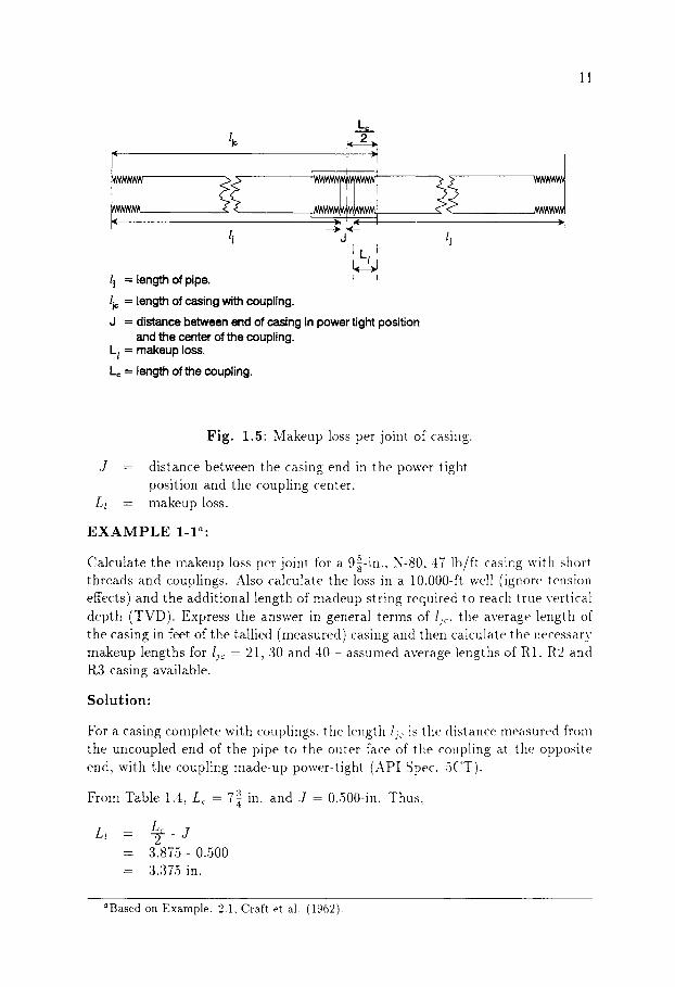
lj - - length of pipe. , t
lj= = length of casing with coupling.
d - distance between end of casing in power tight position and the center of the coupling.
L l = makeup loss.
Lc = length of the coupling.
"1
Fig. 1.5" Makeup loss per joint of casing.
J - distance between the casing end in the power tight position and the coupling center.
Ll - makeup loss.
E X A M P L E 1-1 ~"
5 in. N-80 47 lb/ft casing with short Calculate the makeup loss per joint for a 9~- , . threads and couplings. Also calculate the loss in a 10,000-ft well (ignore tension effects) and the additional length of madeup string required to reach true vertical depth (TVD). Express the answer in general terms of lj~, the average length of the casing in feet of the tallied (measured) casing and then calculate the necessary makeup lengths for ljc = 21, 30 and 40 - assumed average lengths of R1. R2 and R3 casing available.
Solution:
For a casing complete with couplings, the length lj,: is the distance measured fronl the uncoupled end of the pipe to the outer face of the coupling at the opposite end, with the coupling made-up power-tight (API Spec. 5CT).
3 From Table 1.4, L c - 7a in. and J - 0.500-in. Thus,
Ll - @ - J = 3.875- 0.500 = 3.375 in.
aBased on Example. 2.1, Craft et al. (1962).

12
T a b l e 1.4" R o u n d - t h r e a d c a s i n g d i m e n s i o n s for l o n g t h r e a d s and cou- p l ings .
D t dt Lr in. in. in. in.
4.5 All 0.5 7 5 All 0.5 7.75 5.5 All 0.5 8 6.625 All 0.5 8.75 7 All 0.5 9 7.625 All 0.5 9.25 8.625 All 0.5 10 9.625 All 0.5 10.5 t STD 5B ++ Spec 5CT
The number of joints in 1,000 ft of tallied casing is 1.000/lj~ and. therefore, the makeup loss in 1,000 ft is:
Makeup loss per 1,000 ft - 3.375 • 1.000/I~ = 3.375/Ij~ in. = 3,375/(12lj~)ft
As tension effects are ignored this is the makeup loss in a~y 1.000-ft section.
If Lr is defined as the total casing required to make 1.000 ft of nlade-ut), t)ower- tight string, then:
makeup loss = LT 1,000 (3,375 121jc ) ft
3.375) ft 1,000 -- LT -LT f21jc
1,000I/c ) => LT -- lic- 0.28125 ft
Finally, using the general form of the above equation in LT, Table 1.5 can be produced to give the makeup loss in a 10.000-ft string.
1.3.8 Pipe Weight
According to the API Bul. 5C3 (1989), pipe weight is defined as nominal weiglll. plain end weight., and threaded and coupled weight. Pipe weight is usually ex-
~1
76
,-,-
,
1.-,~
m"
.~
i.- I
�9 <
I m
-.
+ i.-
.,,-,
[,4;
0~
,..
+
c <
~ ::
r"
~....
.
O~
""
" ~
[m
c~
~ ='
~
- II
~ ~
" o
~-
~ ~
""
_.
~-.
- 0
~..
. 0
"
~*
~
oo
~
~
m
~
~,~"
.
~'~
"
-
-
I
~
-.
~ ~.
~
..=.=~
=~
~-~
.~
~-~
~ ~-~
..
..
~ ~
r~
0 ~
m"
0~.
...
~)
m"
-.
~ Oo.
~ C
m
~ ~
'~
~ O~
""
"~
~
~
~
. ~
.=-.
+
..,.--
~
" 'T
,-
.~
,--,
- G
"
.~
~:
~ ~
�9
�9
~ ~
~'~
. ~
~ ~
'~
o
~,
~o
'1:)
*m
'--"
I
,~
~_
o~
"~
--
-
~ ~
�9 "
(~.
,-~
m-,
T~
0 L~
..
o~
O~
m~
0
[/I
[/I
C~
C~
[/I
~.de
O~
[/I
14
F -e+'
~~ENTER OF~' ?
I-~ L c --q
TRIANGLE STAM P
L r-
..,---- L 4 - - - - .
I ' - - L2---
E7
A1 - - - - - -
= - ~ + d - - - - -7 COUPLING 7
C ~ N ( ~ E R ~ _
Lc
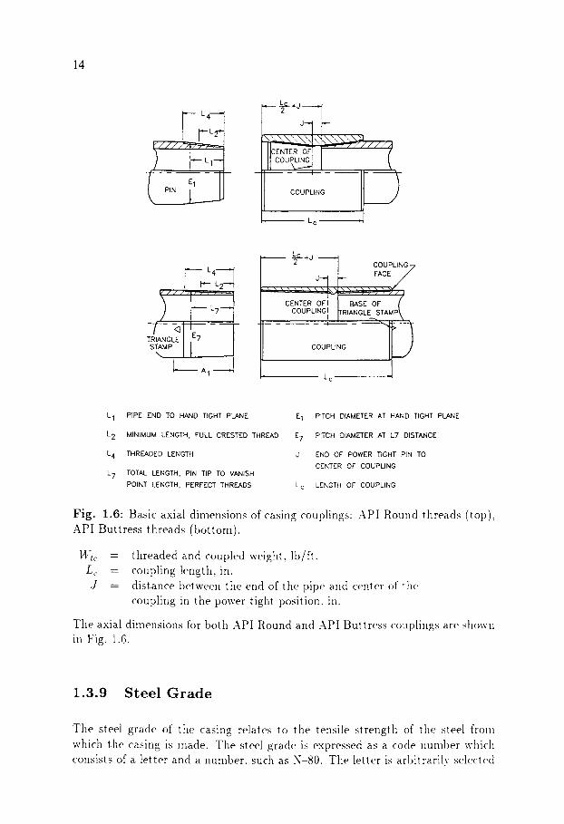
L 1 PIPE END TO HAND TIGHT PLANE E 1
L 2 MINIMUM LENGTH, FULL CRESTED THREAD E 7
L 4 THREADED LENGTH J
L 7 TOTAL LENGTH. PIN TIP TO VANISH
POINT LENGTH, PERFECT THREADS
PITCH DIAMETER AT HAND TIGHT PLANE
PITCH DIAMETER AT L7 DISTANCE
END OF POWER TIGHT PIN TO CENTER OF COUPLING
L c LENGTH OF COUPLING
Fig. 1.6" Basic axial dimensions of casing couplings: API Round threads (top). API Buttress threads (bottom).
I4~c Lc J
= threaded and coupled weight, lb/ft. = coupling length, in. = distance between the end of the pipe and center of the
coupling in the power tight position, in.
Tile axial dimensions for both API Round and API Buttress couplings are shown in Fig. 1.6.
1.3 .9 S t e e l G r a d e
Tile steel grade of the casing relates to the tensile strength of tile steel fronl which the casing is Inade. The steel grade is expressed as a code number which consists of a letter and a number, such as N-80. The letter is arbitrarily selected

"-G
~_~
O
o ,...~
m
�9
~ ~'~
.
~ m
~.~ ,-~
.~
�9 ~N
~ ~
;~.~
o'~
~
�9 "-"
o~ ,_
.
5~
~
k
a.~
~,~
"-"
~ c~
v~
.~
o,-~ r
~,~
rar .,..,
.,.-~
~ h
~ o
0
~r~
�9 ~
~ ~
-4 r
r
0 ~
~ ~
0 ~
C~
d
r~
O
r~ o
.-, �9
;.q
~.~
~
.~
~-~
r
o ,..,,
o,-.~
~ N
<O
.r .r
~ .-4
~
~ ~-~
,--, ,---4 ,---,
~ O
~
O
O
O
O
O
O
O
00
00
00
00
00
O
O
O
O
~
~ O
~
~ ~
O
O
~ O
~
O
O
O
~ ~
O
~ O
O
~
O
~ O
~
~ O
O
~
O
O
O
~ ~
~ ~
O
~ ~
l�9
O
~ O
~
O
O
O
O
O
O
O
O
O
O
~ ~
,-. .
..
..
..
r
,-.
tr tY
3 O
O
~
~ tr
O
~
.,..~
~3
.,..o
e...l
o ~
o ,....~
< Z
< Z
Oca
z
mN
X
0 "~
"G
0
~ r
�9
~r
�9
0
.,.-, "~
:a
,..a
�9 ~ ~
O
""~
c,.)
.~
~b ~
.~
o,-,
~
o
~ ~
17
6
0 ,.
,o
w-.
o
~ �9
,-.-
, ~
...,
.
m
m
~'
~
e K
.~
N
~ N
~
~.
~_
.~
...,
.
~ m
2.
w..
..
�9
~-~
�9
~e
2
~ �9
=
r"
-~
~
=
r'~
w
.-..
~rj
o ~-
�9
~
<
�9
~-"
O
::
r"
�9
�9
~-,
.
o ;~"
~=
~
o ~
m
o~
" =
~
(DO
~-~
~"
++
--
+-
~
o~
w-,
.
,..,
.
&
m
m
~ ~
m
~ m
m
�9
~..
,.
w-,
~-o
F ~~
r-~
~_
~<
o -;
O"
..
oq
=-
0 0 I
Oq
(o)
Thread / - Crest I.--- Lead --J height . ~ / /
(b)
d2 = dl + taper
17
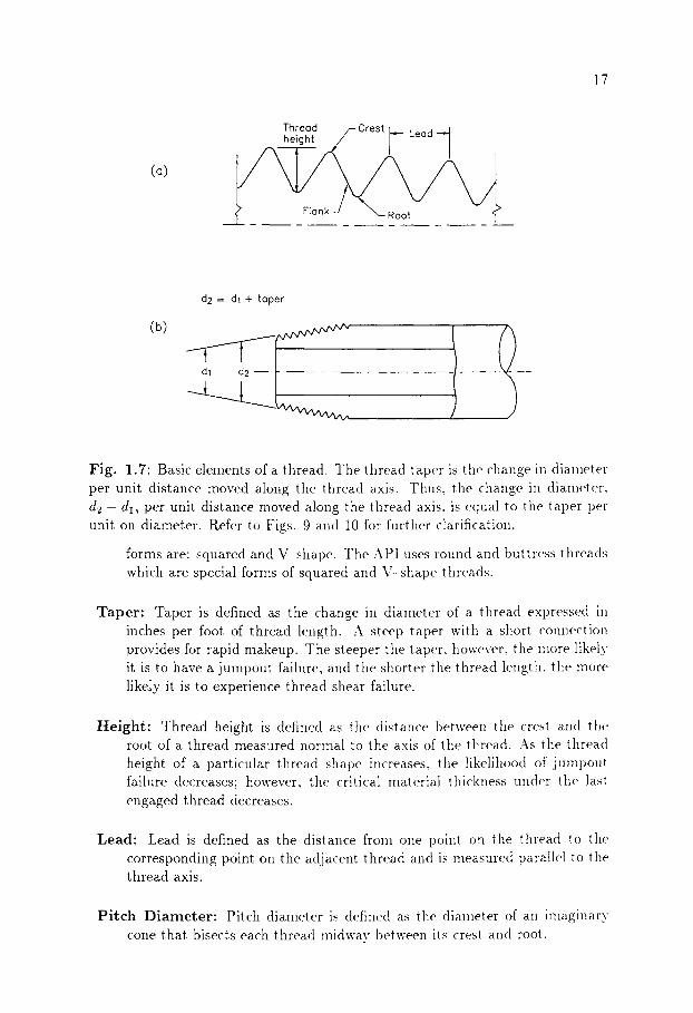
Fig. 1.7" Basic elements of a thread. The thread taper is the change in diameter per unit distance moved along the thread axis. Thus, the change in diameter. d2 -d l , per unit distance moved along the thread axis. is equal to the taper per unit on diameter. Refer to Figs. 9 and 10 for further clarification.
forms are: squared and V-shape. The API uses round and buttress threads which are special forms of squared and \"-shape threads.
Taper" Taper is defined as the change in diameter of a thread expressed in inches per foot of thread length. A steep taper with a short connection provides for rapid makeup. The steeper the taper, however, the more likely it is to have a jumpout failure, and the shorter the thread length, the more likely it is to experience thread shear failure.
Height: Thread height is defined as the distance between the crest aIld the root of a thread measured normal to the axis of the thread. As the thread height of a particular thread shape increases, the likelihood of jumpout failure decreases; however, the critical material thickness under the last engaged thread decreases.
Lead" Lead is defined as the distance from one point oi1 the thread to the corresponding point on the adjacent thread and is measured parallel to the thread axis.
Pitch Diameter: Pitch diameter is defined as the diameter of all imaginary cone that bisects each thread midway between its crest and root.
~"
~--.,
~
,.....,
~ .
. --
.
p
~
C)
t,--
,
~ ~'
~-
""
~ ~'
~ ~-
- o~
=
Z"
~ _-
-..
�9
"~
7"
m ~.
o
m...,
"
"-"
""
"m
~ -,'
- ~
~ .~
--0
, ,--
,- ~
...,
~ ~;
~;
~ ~-'"
,-~
~--.
. .
%-
m-
~-~~
~ =
~
,..,
. .
~..
:,m
�9
�9
~'~
. ~
~ ~
~.~
o
~ =
~~
~8
?~ ~
~ ~ m-
~_~
-- �9
~"
s -
8..
8 ~
=
~
~
o ~
-.,.
~ o
m..,
~ ~
~'~
~
= ~
.~
0
~ ~
0 m
" ..
�9 .
~
"
~
O~
~ o
~ o
~.,
m
"
,_~
~"
~
~;
raC~
r~ ~_
. =
-.~
p
~
"'"
0 �9
,-..
0 ~
; m
-"
,-,-
�9
0 �9
,.
. ~
[m
b--,
.
o
0 ~
"
~)"
~-
~ o
~-~
0 [m
9 n)
�9
(~
, ,-
,.
" ,'T
m-"
n)
~
. m
-.
~,
="
rT
~.
m"
r~
~..
..
0 ,-
-t.
'-"
,'T
~_,
.
~ .~
"
�9
_----
" ,..
..~
c~
19
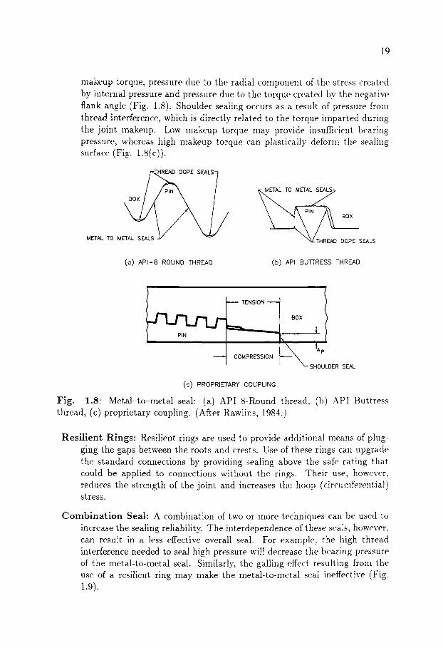
makeup torque, pressure due to the radial component of the stress created by internal pressure and pressure due to the torque created by the negative flank angle (Fig. 1.8). Shoulder sealing occurs as a result of pressure from thread interference, which is directly related to the torque imparted during the joint makeup. Low makeup torque may provide insufficient bearing pressure, whereas high makeup torque can plastically deform tlle sealing surface (Fig. 1.8(c)).
"HREAD DOPE SEALS 7
METAL TO METAL SEALS ~I~#._THREAD DOPE SEALS
(o) API-8 ROUND THREAD (b) API BUTTRESS THREAD
~ L j ~ ~ ENSION =i BOX
------ COMPRESSION
t i tap
SHOULDER SEAL
(C) PROPRIETARY COUPLING
Fig . 1.8: Metal-to-metal seal: (a) API 8-Round thread, (b) API Buttress thread, (c) proprietary coupling. (After Rawlins, 1984.)
Resi l ient Rings" Resilient rings are used to provide additional means of plug- ging the gaps between the roots and crests. Use of these rings can upgrade the standard connections by providing sealing above the safe rating that could be applied to connections without the rings. Their use, however, reduces the strength of the joint and increases the hoop (circumferential) stress.
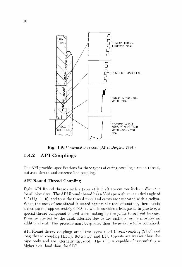
C o m b i n a t i o n Seal" A combination of two or more techniques can be used to increase the sealing reliability. The interdependence of these seals, however, can result in a less effective overall seal. For example, the high thread interference needed to seal high pressure will decrease the bearing pressure of the metal-to-metal seal. Similarly, the galling effect resulting from the use of a resilient ring may make the metal-to-Inetal seal ineffective (Fig. 1.9).
20
COUPLING
THREAD INTER- FERENCE SEAL
RESILIENT RING SEAL
RADIAL METAL-TO- METAL SEAL
REVERSE ANGLE TORQUE SHOULDER M ETAL- TO- M ETAL SEAL
1.4.2
Fig. 1.9: Combination seals. (After Biegler, 1984.)
A P I Couplings
The API provides specifications for three types of casing couplings" round thread, buttress thread and extreme-line coupling.
API Round Thread Coupling
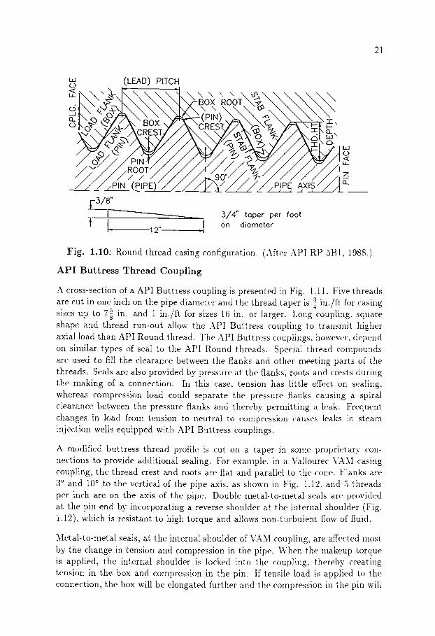
3 in./ft are cut per inch oil diameter Eight API Round threads with a taper of for all pipe sizes. The API Round thread has a V-shape with an included angle of 60 ~ (Fig. 1.10), and thus the thread roots and crests are truncated with a radius. When the crest of one thread is mated against the root of another, there exists a clearance of approximately 0.003-in. which provides a leak path. In practice, a special thread compound is used when making up two joints to prevent leakage. Pressure created by the flank interface due to the makeup torque provides an additional seal. This pressure must be greater than the pressure to be contained.
API Round thread couplings are of two types: short thread coupling (STC) and long thread coupling (LTC). Both ST(' and LTC threads are weaker than the pipe body and are internally threaded. The LTC is capable of transmitting a higher axial load than the STC.
21
i , I (D
Sk \ r
(LEAD) PITCH
" xN, Q BOX ROOT~"~ >
,~ \CRESTY"/~ \,,~\~., ~ ' \ ~ t ~" o %. ci•
Oa "r _u 13_,,
Z Z :,4./p,,, ZZ /P.IN (PIPE)" _ a_
3/8"
t k F - 12". =]
3/4" toper per foot on diometer
Fig. 1.10: Round thread casing configuration. (After API RP 5B1, 1988.)
API Buttress Thread Coupling
A cross-section of a API Buttress coupling is presented in Fig. 1.11. Five threads a in./ft for casing are cut in one inch on the pipe diameter and the thread taper is
s sizes up to 7g in. and 1 in./ft for sizes 16 in. or larger. Long coupling, square shape and thread run-out allow the API Buttress coupling to transmit higher axial load than API Round thread. The API Buttress couplings, however, depend on similar types of seal to the API Round threads. Special thread compounds are used to fill the clearance between the flanks and other meeting parts of the threads. Seals are also provided by pressure at the flanks, roots and crests during the making of a connection. In this case, tension has little effect on sealing, whereas compression load could separate the pressure flanks causing a spiral clearance between the pressure flanks and thereby permitting a leak. Frequent changes in load from tension to neutral to compression causes leaks ix: steam injection wells equipped with API Buttress couplings.
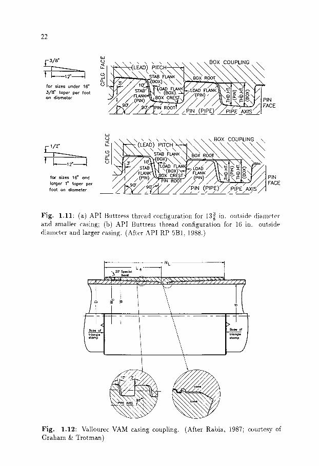
A modified buttress thread profile is cut on a taper in some proprietary con- nections to provide additional sealing. For example, in a Vallourec VAM casing coupling, the thread crest and roots are flat and parallel to the cone. Flanks are 3 ~ and 10 ~ to the vertical of the pipe axis. as shown in Fig. 1.12. and 5 threads per inch are on the axis of the pipe. Double metM-to-metal seals are provided at the pin end by incorporating a reverse shoulder at the internal shoulder (Fig. 1.12), which is resistant to high torque and allows non-turbulent flow of fluid.
Metal-to-metal seals, at the internal shoulder of VAM coupling, are affected most by the change in tension and compression in the pipe. When the makeup torque is applied, the internal shoulder is locked into the coupling, thereby creating tension in the box and compression in the pin. If tensile load is applied to the connection, the box will be elongated further and the compression in the pin will
22
3/a-
! ~ ,2" J for sizes under 16" 3/8" toper per foot on diometer
w (.) '. .. ,. ,. \ \ \ \ \ \ \ B O X COUPLING \(LEAD) P ~ T C . ~ \ \ \ \ ~ \ \ \ "
\ \ \ \ " K \ \ \ \ ~ \
" / r ~ { " " ~ B O , x .C:RESI.T"J" / ~ " 2 / A ~ \ N I ~ ' N I ~ " , ~ , / ; 5 , , ; , , ~ / / / / / ~ p,N FACE
C / / ' Y & " ; " ~ ' 7 / _ P I N . (P IPE) : / P ~ # E " . ~ S
j-- 1/2"
t L ,~_J
for sizes 16" end Iorger 1" toper per foot on diometer
\ ,, \ \ \ \ \ \ \ B O X COUPLING \
l~/ (BOX) FLANK d E" ~; o \ LOAD -1- ~" "I- ,~-
,d I / / 7 - , . / . 9~ PIN (PIPE) PIPE AXIS I
3 Fig. 1.11" (a) API Buttress thread configuration for 13g in. outside diameter and smaller casing; (b) API Buttress thread configuration for 16 in. outside diameter and larger casing. (After API RP 5B1, 1988.)
L 4 - - - - - - - - ,,~20" Spec;~l bevel
NL
]n R "O
Fig. 1.12" Vallourec VAM casing coupling. Graham & Trotman)
(After Rabia, 1987; courtesy of

23
~~~~x~X'BOX(COUPLING) x"X.~~~~X'~
ETAL TO ETAL SEAL
314" ~518"
rL_, _J r-L_,, _! For sizes 7 5/8" and smoller For sizes Iorger thon 7 5 /8"
1 1/2" toper per foot on 1 1/4" toper per foot on
diameter 6 pitch thread d i a m e t e r 5 pitch th read
Fig. 1.13" API Extreme-line casing thread configuration. (After API RP 5B1, 1988.)
be reduced due to the added load. Should the tensile load exceed the critical value, the shoulders may separate.
API Extreme-l ine Thread Coupling
API Extreme-line coupling differs from API Round thread and API Buttress thread couplings in that it is an integral joint, i.e., the box is machined into the pipe wall. With integral connectors, casing is made internally and externally upset to compensate for the loss of wall thickness due to threading. The thread profile is trapezodial and additional metal-to-metal seal is provided at the pin end and external shoulder. As a result, API Extreme-line couplings do not require any sealing compound, although the compound is still necessary for lubrication. The metal-to-metal seal at the external shoulder of the pin is affected in the same way as VAM coupling when axial load is applied.
In an API Extreme-line coupling, 6 threads per inch are cut on pipe sizes of 5 5 1 in. to 7~ in. with 13 in./ft of taper and 5 threads per inch are cut on pipe sizes
of 8~5 in. to 10~3 in. with l al in./ft of taper. Figure 1.13 shows different design features of API Extreme--line coupling.

24
1.4.3 Proprietry Couplings
In recent years, many proprietary couplings with premium design features have been developed to meet special drilling and production requirements. Some of these features are listed below.
Flush Joints" Flush joints are used to provide maximal annular clearance in order to avoid tight spots and to improve the cement bond.
Smoo th Bores" Smooth bores through connectors are necessary to avoid tur- bulent flow of fluid.
Fast M a k e u p Threads- Fast makeup threads are designed to facilitate fast makeup and reduce the tendency to cross-thread.
M e t a l - t o - M e t a l Seals" Multiple metal-to-metal seals are designed to provide improved joint strength and pressure containment.
Mul t ip le Shoulders: Use of multiple shoulders can provide improved sealing characteristics with adequate torque and compressive strength.
Special Tooth Form" Special tooth form, e.g., a squarer shape with negative flank angle provide improved joint strength and sealing characteristics.
Resil ient Rings" If resilient rings are correctly designed, they can serve as secondary pressure seals in corrosive and high-temperature environments.
25
1.5 R E F E R E N C E S
Adams, N.J., 1985. Drilling Engineering- A Complete Well Planning Approach. Penn Well Books, Tulsa, OK, pp. 357-366,385.
API Bul. 5C3, 5th Edition, July 1989. Bulletin on Formulas and Calculations for Casing, Tubing, Drill Pipe and Line Pipe Properties. API Production De- partment.
API Specification STD 5B, 13th Edition, May 31, 1988. Specification for Thread- ing, Gaging, and Thread Inspection of Casing, Tubing, and Line Pipe Threads. API Production Department.
API RP 5B1, 3rd Edition, June 1988. Recommended Practice for Gaging and Inspection of Casing, Tubing and Pipe Line Threads. API Production Depart- ment.
API Specification 5CT, 3rd Edition, Nov. 1, 1992. Specification for Casing and Tubing. API Production Department.
Biegler, K.K., 1984. Conclusions Based on Laboratory Tests of Tubing and Casing Connections. SPE Paper No. 13067, Presented at 59th Annu. Techn. Conf. and Exhib., Houston, TX, Sept. 16-19.
Bourgoyne A.T., Jr., Chenevert, M.E., Millheim, K.K. and Young, F.S., Jr., 1985. Applied Drilling Engineering. SPE Textbook Series, Vol. 2, Richardson, TX, USA, pp. 300-306.
Brown-Hughes Co., 1984. Technical Catalogue.
Buzarde, L.E., Jr., Kastro, R.L., Bell, W.T. and Priester C.L., 1972. Production Operations, Course 1. SPE, pp. 132-172.
Craft, B.C., Holden, W.R. and Graves, E.D., Jr., 1962. Well Design" Drilling and Production. Prentice-Hall, Inc., Englewood Cliffs, N.J, USA, pp. 108-109.
Rabia, H., 1987. Fundamentals of Casing Design. Graham & Trotman, London, UK, pp. 1-2:].
Rawlins, M., 1984. How loading affects tubular thread shoulder seals. Petrol. Engr. Internat., 56" 43-52.