Embed Size (px)
Citation preview

Chapter 1: Introduction: Waves and Phasors Lesson #1 Chapter — Section: Chapter 1 Topics: EM history and how it relates to other fields Highlights:
• EM in Classical era: 1000 BC to 1900 • Examples of Modern Era Technology timelines • Concept of “fields” (gravitational, electric, magnetic) • Static vs. dynamic fields • The EM Spectrum
Special Illustrations:
• Timelines from CD-ROM
Timeline for Electromagnetics in the Classical Era ca. 900 Legend has it that while walking BC across a field in northern Greece, a
shepherd named Magnus experiences a pull on the iron nails in his sandals by the black rock he was standing on. The region was later named Magnesia and the rock became known as magnetite [a form of iron with permanent magnetism].
ca. 600 Greek philosopher Thales BC describes how amber,
after being rubbed with cat fur, can pick up feathers [static electricity].
ca. 1000 Magnetic compass used as a navigational device.
1752 Benjamin Franklin (American) invents the
lightning rod and demonstrates that lightning is electricity.
1785 Charles-Augustin de
Coulomb (French) demonstrates that the electrical force between charges is proportional to the inverse of the square of the distance between them.
1800 Alessandro Volta
(Italian) develops the first electric battery.
1820 Hans Christian Oersted (Danish) demonstrates the interconnection between electricity and magnetism through his discovery that an electric current in a wire causes a compass needle to orient itself perpendicular to the wire.
2
Lessons #2 and 3 Chapter — Sections: 1-1 to 1-6 Topics: Waves Highlights:
• Wave properties • Complex numbers • Phasors
Special Illustrations:
• CD-ROM Modules 1.1-1.9 • CD-ROM Demos 1.1-1.3

CHAPTER 1 3
Chapter 1
Section 1-3: Traveling Waves
Problem 1.1 A 2-kHz sound wave traveling in the x-direction in air was observed tohave a differential pressure p
x t 10 N/m2 at x 0 and t 50 µs. If the reference
phase of px t is 36 , find a complete expression for p
x t . The velocity of sound
in air is 330 m/s.
Solution: The general form is given by Eq. (1.17),
px t Acos
2πtT 2πx
λ φ0 where it is given that φ0 36 . From Eq. (1.26), T 1 f 1 2 103 0 5 ms.From Eq. (1.27),
λ up
f 330
2 103 0 165 m Also, since
px 0 t 50 µs 10 (N/m2) Acos
2π 50 10 6
5 10 4 36 π rad180 Acos
1 26 rad 0 31A
it follows that A 10 0 31 32 36 N/m2. So, with t in (s) and x in (m),
px t 32 36cos 2π 106 t
500 2π 103 x165 36 (N/m2) 32 36cos
4π 103t 12 12πx 36 (N/m2)
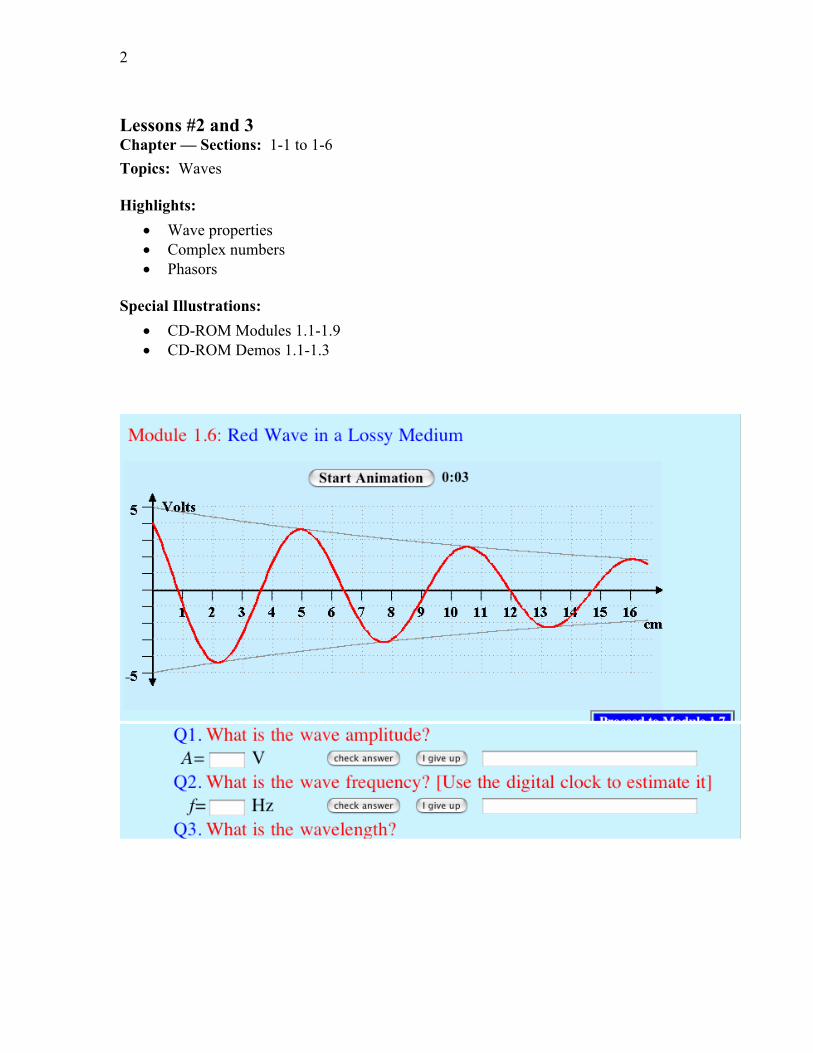
Problem 1.2 For the pressure wave described in Example 1-1, plot(a) p
x t versus x at t 0,
(b) px t versus t at x 0.
Be sure to use appropriate scales for x and t so that each of your plots covers at leasttwo cycles.
Solution: Refer to Fig. P1.2(a) and Fig. P1.2(b).
4 CHAPTER 1
0.00 0.25 0.50 0.75 1.00 1.25 1.50 1.75 2.00 2.25 2.50 2.75 3.00-12.
-10.
-8.
-6.
-4.
-2.
0.
2.
4.
6.
8.
10.
12.
Am
plitu
de(N
/m2 )
Distance x (m)
p(x,t=0)
0.0 0.2 0.4 0.6 0.8 1.0 1.2 1.4 1.6 1.8 2.0-12.
-10.
-8.
-6.
-4.
-2.
0.
2.
4.
6.
8.
10.
12.
Am
plitu
de(N
/m2 )
Time t (ms)
p(x=0,t)
(a) (b)
Figure P1.2: (a) Pressure wave as a function of distance at t 0 and (b) pressurewave as a function of time at x 0.
Problem 1.3 A harmonic wave traveling along a string is generated by an oscillatorthat completes 180 vibrations per minute. If it is observed that a given crest, ormaximum, travels 300 cm in 10 s, what is the wavelength?
Solution:
f 18060
3 Hz up 300 cm
10 s 0 3 m/s
λ up
f 0 3
3 0 1 m 10 cm
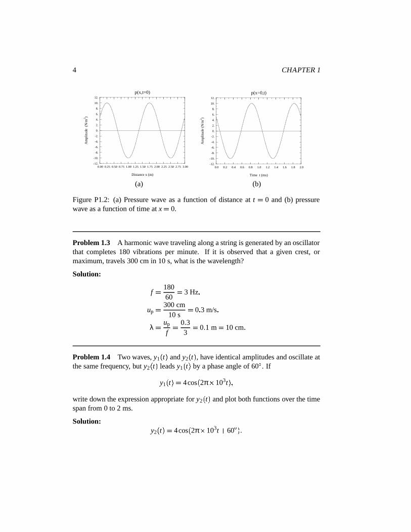
Problem 1.4 Two waves, y1t and y2
t , have identical amplitudes and oscillate at
the same frequency, but y2t leads y1
t by a phase angle of 60 . If
y1t 4cos
2π 103t
write down the expression appropriate for y2t and plot both functions over the time
span from 0 to 2 ms.
Solution:y2t 4cos
2π 103t 60
CHAPTER 1 5
0
4
2
-2
-4
0.5 ms 1 ms 1.5 ms 2 ms
y (t)1
y (t)2
z
Figure P1.4: Plots of y1t and y2
t .
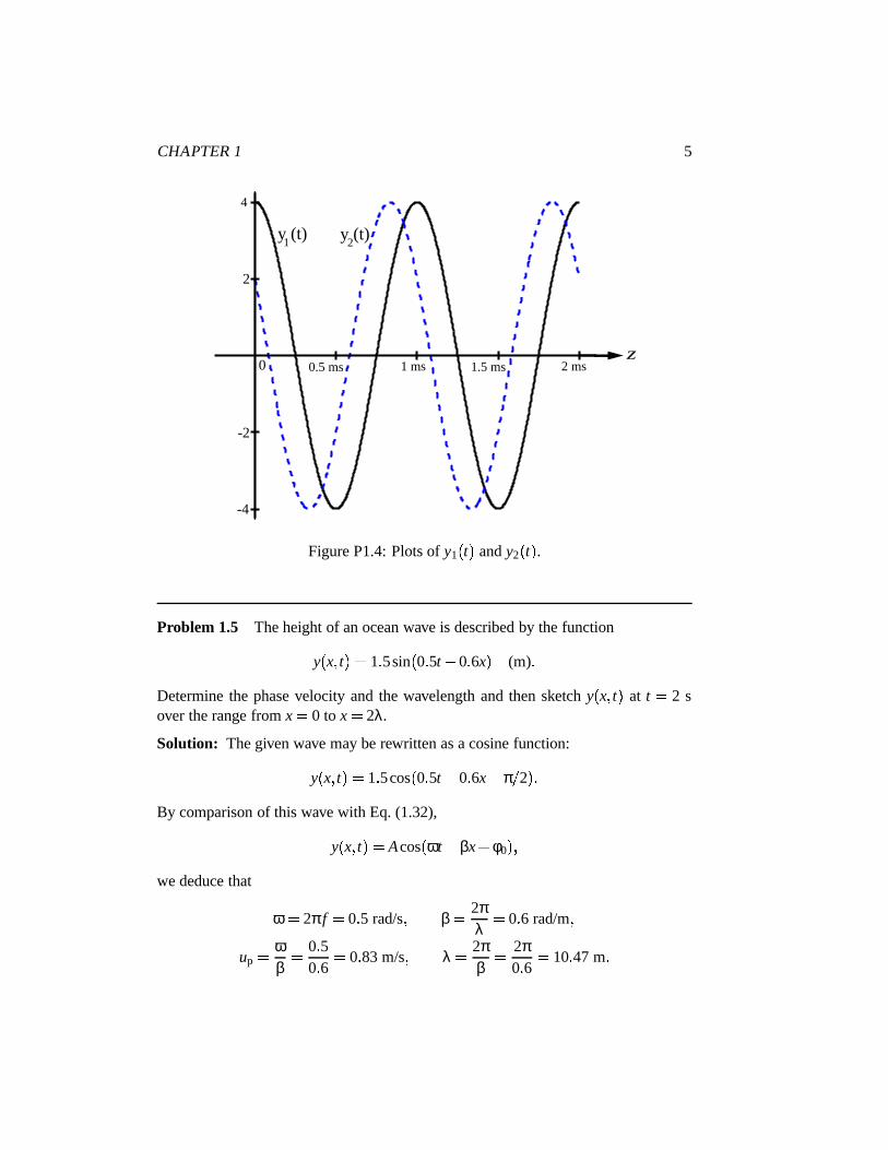
Problem 1.5 The height of an ocean wave is described by the function
yx t 1 5sin
0 5t 0 6x (m)
Determine the phase velocity and the wavelength and then sketch yx t at t 2 s
over the range from x 0 to x 2λ.
Solution: The given wave may be rewritten as a cosine function:
yx t 1 5cos
0 5t 0 6x π 2
By comparison of this wave with Eq. (1.32),
yx t Acos
ωt βx φ0
we deduce that
ω 2π f 0 5 rad/s β 2πλ
0 6 rad/m up ω
β 0 5
0 6 0 83 m/s λ 2πβ
2π0 6 10 47 m

6 CHAPTER 1
2λx
1.5
1
0.5
0
-0.5
-1
-1.5
y (π/2, t)
Figure P1.5: Plot of yx 2 versus x.
At t 2 s, yx 2 1 5sin
1 0 6x (m), with the argument of the cosine function
given in radians. Plot is shown in Fig. P1.5.
Problem 1.6 A wave traveling along a string in the x-direction is given by
y1x t Acos
ωt βx
where x 0 is the end of the string, which is tied rigidly to a wall, as shown inFig. 1-21 (P1.6). When wave y1
x t arrives at the wall, a reflected wave y2
x t is
generated. Hence, at any location on the string, the vertical displacement ys will bethe sum of the incident and reflected waves:
ysx t y1
x t y2
x t
(a) Write down an expression for y2x t , keeping in mind its direction of travel
and the fact that the end of the string cannot move.(b) Generate plots of y1
x t , y2
x t and ys
x t versus x over the range 2λ
x
0 at ωt π 4 and at ωt π 2.
Solution:(a) Since wave y2
x t was caused by wave y1
x t , the two waves must have the
same angular frequency ω, and since y2x t is traveling on the same string as y1
x t ,

CHAPTER 1 7
x
x = 0
Incident Wave
y
Figure P1.6: Wave on a string tied to a wall at x 0 (Problem 1.6).
the two waves must have the same phase constant β. Hence, with its direction beingin the negative x-direction, y2
x t is given by the general form
y2x t Bcos
ωt βx φ0 (1)
where B and φ0 are yet-to-be-determined constants. The total displacement is
ysx t y1
x t y2
x t Acos
ωt βx Bcos
ωt βx φ0
Since the string cannot move at x 0, the point at which it is attached to the wall,ys0 t 0 for all t. Thus,
ys0 t Acosωt Bcos
ωt φ0 0 (2)
(i) Easy Solution: The physics of the problem suggests that a possible solution for(2) is B A and φ0 0, in which case we have
y2x t Acos
ωt βx (3)
(ii) Rigorous Solution: By expanding the second term in (2), we have
Acosωt Bcosωt cosφ0 sinωt sin φ0 0
or A Bcosφ0 cos ωt
Bsinφ0 sin ωt 0 (4)
This equation has to be satisfied for all values of t. At t 0, it gives
A Bcosφ0 0 (5)

8 CHAPTER 1
and at ωt π 2, (4) gives
Bsinφ0 0 (6)
Equations (5) and (6) can be satisfied simultaneously only if
A B 0 (7)
or
A B and φ0 0 (8)
Clearly (7) is not an acceptable solution because it means that y1x t 0, which is
contrary to the statement of the problem. The solution given by (8) leads to (3).(b) At ωt π 4,
y1x t Acos
π 4 βx Acos
π4 2πx
λ y2x t Acos
ωt βx Acos
π4 2πx
λ Plots of y1, y2, and y3 are shown in Fig. P1.6(b).
y (ωt, x)2
y (ωt, x)s
0
A
-A
-2λx
1.5A
-1.5A
ωt=π/4
y (ωt, x)1
Figure P1.6: (b) Plots of y1, y2, and ys versus x at ωt π 4.
At ωt π 2,
y1x t Acos
π 2 βx Asinβx Asin
2πxλ

CHAPTER 1 9
y2x t Acos
π 2 βx Asinβx Asin
2πxλ
Plots of y1, y2, and y3 are shown in Fig. P1.6(c).
y (ωt, x)2
y (ωt, x)s
0
A
-A
-2λx
2A
-2A
ωt=π/2
y (ωt, x)1
Figure P1.6: (c) Plots of y1, y2, and ys versus x at ωt π 2.
Problem 1.7 Two waves on a string are given by the following functions:
y1x t 4cos
20t 30x (cm)
y2x t 4cos
20t 30x (cm)
where x is in centimeters. The waves are said to interfere constructively when theirsuperposition ys y1 y2 is a maximum and they interfere destructively when ys is a minimum.
(a) What are the directions of propagation of waves y1x t and y2
x t ?
(b) At t π 50 s, at what location x do the two waves interfere constructively,
and what is the corresponding value of ys ?(c) At t
π 50 s, at what location x do the two waves interfere destructively,and what is the corresponding value of ys ?
Solution:(a) y1
x t is traveling in positive x-direction. y2
x t is traveling in negative
x-direction.

10 CHAPTER 1
(b) At t π 50 s, ys y1 y2 4 cos
0 4π 30x cos
0 4π 3x . Using the
formulas from Appendix C,
2sin xsin y cosx y
cosx y we have
ys 8sin0 4π sin 30x 7 61sin 30x
Hence,
ys max 7 61
and it occurs when sin 30x 1, or 30x π2 2nπ, or x
π60 2nπ
30 cm, where
n 0 1 2 (c) ys min 0 and it occurs when 30x nπ, or x nπ
30cm.
Problem 1.8 Give expressions for yx t for a sinusoidal wave traveling along a
string in the negative x-direction, given that ymax 40 cm, λ 30 cm, f 10 Hz,and
(a) yx 0 0 at x 0,
(b) yx 0 0 at x 7 5 cm.
Solution: For a wave traveling in the negative x-direction, we use Eq. (1.17) withω 2π f 20π (rad/s), β 2π λ 2π 0 3 20π 3 (rad/s), A 40 cm, and xassigned a positive sign:
yx t 40cos
20πt 20π
3x φ0 (cm)
with x in meters.(a) y
0 0 0 40cos φ0. Hence, φ0 π 2, and
yx t 40cos
20πt 20π
3x π
2 40sin 20πt 20π
3 x (cm), if φ0 π 2 40sin 20πt 20π
3 x (cm), if φ0 π 2 (b) At x 7 5 cm = 7 5 10 2 m, y 0 40cos
π 2 φ0 . Hence, φ0 0 or π,
and
yx t
40cos 20πt 20π3 x (cm), if φ0 0 40cos 20πt 20π
3 x (cm), if φ0 π
CHAPTER 1 11
Problem 1.9 An oscillator that generates a sinusoidal wave on a string completes20 vibrations in 50 s. The wave peak is observed to travel a distance of 2.8 m alongthe string in 50 s. What is the wavelength?
Solution:
T 5020
2 5 s up 2 85
0 56 m/s λ upT 0 56 2 5 1 4 m
Problem 1.10 The vertical displacement of a string is given by the harmonicfunction:
yx t 6cos
16πt 20πx (m)
where x is the horizontal distance along the string in meters. Suppose a tiny particlewere to be attached to the string at x 5 cm, obtain an expression for the verticalvelocity of the particle as a function of time.
Solution:yx t 6cos
16πt 20πx (m)
u0 05 t dy
x t
dt x 0 05 96πsin
16πt 20πx x 0 05 96πsin16πt π 96πsin16πt (m/s)
Problem 1.11 Given two waves characterized by
y1t 3cos ωt
y2t 3sin
ωt 36
does y2t lead or lag y1
t , and by what phase angle?
Solution: We need to express y2t in terms of a cosine function:
y2t 3sin
ωt 36 3cos π
2 ωt 36 3cos54 ωt 3cos
ωt 54
12 CHAPTER 1
Hence, y2t lags y1
t by 54 .
Problem 1.12 The voltage of an electromagnetic wave traveling on a transmissionline is given by v
z t 5e αz sin
4π 109t 20πz (V), where z is the distance in
meters from the generator.(a) Find the frequency, wavelength, and phase velocity of the wave.(b) At z 2 m, the amplitude of the wave was measured to be 1 V. Find α.
Solution:(a) This equation is similar to that of Eq. (1.28) with ω 4π 109 rad/s and
β 20π rad/m. From Eq. (1.29a), f ω 2π 2 109 Hz 2 GHz; fromEq. (1.29b), λ 2π β 0 1 m. From Eq. (1.30),
up ω β 2 108 m/s (b) Using just the amplitude of the wave,
1 5e α2 α 12 m
ln
15 0 81 Np/m.
Problem 1.13 A certain electromagnetic wave traveling in sea water was observedto have an amplitude of 98.02 (V/m) at a depth of 10 m and an amplitude of 81.87(V/m) at a depth of 100 m. What is the attenuation constant of sea water?
Solution: The amplitude has the form Aeαz. At z 10 m,
Ae 10α 98 02
and at z 100 m,Ae 100α 81 87
The ratio givese 10α
e 100α 98 0281 87
1 20
ore 10α 1 2e 100α
Taking the natural log of both sides gives
lne 10α ln
1 2e 100α
10α ln1 2 100α
90α ln1 2 0 18
Hence,
α 0 1890
2 10 3 (Np/m)

CHAPTER 1 13
Section 1-5: Complex Numbers
Problem 1.14 Evaluate each of the following complex numbers and express theresult in rectangular form:
(a) z1 4e jπ 3,(b) z2 3 e j3π 4,(c) z3 6e jπ 2,(d) z4 j3,(e) z5 j 4,(f) z6
1 j 3,(g) z7
1 j 1 2.
Solution: (Note: In the following solutions, numbers are expressed to only twodecimal places, but the final answers are found using a calculator with 10 decimalplaces.)
(a) z1 4e jπ 3 4cos π 3 j sinπ 3 2 0 j3 46.
(b)
z2 3e j3π 4 3
cos
3π4 j sin
3π4 1 22 j1 22 1 22
1 j (c) z3 6e jπ 2 6 cos
π 2 j sin π 2 j6.
(d) z4 j3 j j2 j, or
z4 j3 e jπ 2 3 e j3π 2 cos
3π 2 j sin
3π 2 j
(e) z5 j 4 e jπ 2 4 e j2π 1.
(f)
z6 1 j 3 2e jπ 4 3 2 3e j3π 4 2 3 cos
3π 4 j sin
3π 4 2 j2 2
1 j
(g)
z7 1 j 1 2 2e jπ 4 1 2 21 4e jπ 8 1 19
0 92 j0 38 1 10 j0 45
Problem 1.15 Complex numbers z1 and z2 are given by
z1 3 j2 z2 4 j3
14 CHAPTER 1
(a) Express z1 and z2 in polar form.(b) Find z1 by applying Eq. (1.41) and again by applying Eq. (1.43).(c) Determine the product z1z2 in polar form.(d) Determine the ratio z1 z2 in polar form.(e) Determine z3
1 in polar form.
Solution:(a) Using Eq. (1.41),
z1 3 j2 3 6e j33 7 z2 4 j3 5e j143 1
(b) By Eq. (1.41) and Eq. (1.43), respectively,
z1 3 j2 32 2 2 13 3 60 z1
3 j2 3 j2 13 3 60 (c) By applying Eq. (1.47b) to the results of part (a),
z1z2 3 6e j33 7 5e j143 1 18e j109 4 (d) By applying Eq. (1.48b) to the results of part (a),
z1
z2 3 6e j33 7
5e j143 1 0 72e j176 8 (e) By applying Eq. (1.49) to the results of part (a),
z31
3 6e j33 7 3 3 6 3e j3 33 7 46 66e j101 1
Problem 1.16 If z 2 j4, determine the following quantities in polar form:(a) 1 z,(b) z3,(c) z 2,(d) z ,(e) z .
Solution: (Note: In the following solutions, numbers are expressed to only twodecimal places, but the final answers are found using a calculator with 10 decimalplaces.)

CHAPTER 1 15
(a)
1z 1
2 j4 2 j4 1
4 47e j116 6 1 4 47 1e j116 6 0 22e j116 6
(b) z3 2 j4 3 4 47e j116 6 3
4 47 3e j350 0 89 44e j10 .(c) z 2 z z 2 j4 2 j4 4 16 20.(d) z 2 j4 4.(e) z 2 j4 4 4e jπ.
Problem 1.17 Find complex numbers t z1 z2 and s z1 z2, both in polar form,for each of the following pairs:
(a) z1 2 j3, z2 1 j3,(b) z1 3, z2 j3,(c) z1 3
30 , z2 3
30 ,(d) z1 3
30 , z2 3
150 .
Solution:(a)
t z1 z2 2 j3
1 j3 3 s z1 z2
2 j3 1 j3 1 j6 6 08e j80 5
(b)
t z1 z2 3 j3 4 24e j45 s z1 z2 3 j3 4 24e j45
(c)
t z1 z2 3
30 3 30 3e j30 3e j30
2 6 j1 5 2 6 j1 5 5 2
s z1 z2 3e j30 3e j30 2 6 j1 5
2 6 j1 5 j3 3e j90 (d)
t z1 z2 3
30 3 150
2 6 j1 5 2 6 j1 5 0 s z1 z2
2 6 j1 5 2 6 j1 5 5 2 j3 6e j30 Problem 1.18 Complex numbers z1 and z2 are given by
z1 5 60
z2 2
45

16 CHAPTER 1
(a) Determine the product z1z2 in polar form.(b) Determine the product z1z 2 in polar form.(c) Determine the ratio z1 z2 in polar form.(d) Determine the ratio z 1 z 2 in polar form.(e) Determine z1 in polar form.
Solution:(a) z1z2 5e j60 2e j45 10e j15 .(b) z1z 2 5e j60 2e j45 10e j105 .(c)
z1
z2 5e j60
2e j45 2 5 j105 .(d)
z 1z 2
z1
z2 2 5 j105 .
(e) z1 5e j60 5e j30 .Problem 1.19 If z 3 j5, find the value of ln
z .
Solution:
z 32 52 5 83 θ tan 1
53 59
z z e jθ 5 83e j59 lnz ln
5 83e j59 ln5 83 ln
e j59 1 76 j59 1 76 j
59 π180 1 76 j1 03
Problem 1.20 If z 3 j4, find the value of ez.
Solution:
ez e3 j4 e3 e j4 e3 cos4 j sin4 e3 20 09 and 4 rad 4
π 180 229 18
Hence, ez 20 08cos 229 18 j sin229 18 13 13 j15 20.

CHAPTER 1 17
Section 1-6: Phasors
Problem 1.21 A voltage source given by vst 25cos
2π 103t 30 (V) is
connected to a series RC load as shown in Fig. 1-19. If R 1 MΩ and C 200 pF,obtain an expression for vc
t , the voltage across the capacitor.
Solution: In the phasor domain, the circuit is a voltage divider, and
Vc
Vs1 jωC
R 1 jωC
Vs1 jωRC
NowVs 25e j30 V with ω 2π 103 rad/s, so
Vc 25e j30 V
1 j
2π 103 rad/s 106 Ω
200 10 12 F 25e j30 V
1 j2π 5 15 57e j81 5 V.
Converting back to an instantaneous value,
vct
Vce jωt 15 57e j ωt 81 5 V 15 57cos
2π 103t 81 5 V
where t is expressed in seconds.
Problem 1.22 Find the phasors of the following time functions:(a) v
t 3cos
ωt π 3 (V),
(b) vt 12sin
ωt π 4 (V),
(c) ix t 2e 3x sin
ωt π 6 (A),
(d) it 2cos
ωt 3π 4 (A),
(e) it 4sin
ωt π 3 3cos
ωt π 6 (A).
Solution:(a)
V 3e jπ 3 V.
(b) vt 12sin
ωt π 4 12cos
π 2
ωt π 4 12cosωt π 4 V,
V 12e jπ 4 V.(c)
it 2e 3x sin
ωt π 6 A 2e 3x cos
π 2
ωt π 6 A 2e 3x cosωt π 3 A
I 2e 3xe jπ 3 A

18 CHAPTER 1
(d)
it 2cos
ωt 3π 4
I 2e j3π 4 2e jπe j3π 4 2e jπ 4 A (e)
it 4sin
ωt π 3 3cos
ωt π 6 4cos π 2
ωt π 3 3cosωt π 6 4cos
ωt π 6 3cosωt π 6 4cos
ωt π 6 3cos
ωt π 6 7cos
ωt π 6
I 7e jπ 6 A Problem 1.23 Find the instantaneous time sinusoidal functions corresponding tothe following phasors:
(a)V 5e jπ 3 (V),
(b)V j6e jπ 4 (V),
(c)I
6 j8 (A),(d) I 3 j2 (A),(e) I j (A),(f) I 2e jπ 6 (A).
Solution:(a)
V 5e jπ 3 V 5e j π 3 π V 5e j2π 3 V
vt 5cos
ωt 2π 3 V
(b)V j6e jπ 4 V 6e j π 4 π 2 V 6e jπ 4 V
vt 6cos
ωt π 4 V
(c)I
6 j8 A 10e j53 1 A it 10cos
ωt 53 1 A.
(d)I 3 j2 3 61e j146 31
it 3 61e j146 31 e jωt 3 61 cos
ωt 146 31 A

CHAPTER 1 19
(e)I j e jπ 2
it e jπ 2e jωt cos
ωt π 2 sinωt A
(f)I 2e jπ 6
it 2e jπ 6e jωt 2cos
ωt π 6 A
Problem 1.24 A series RLC circuit is connected to a generator with a voltagevst V0 cos
ωt π 3 (V).
(a) Write down the voltage loop equation in terms of the current it , R, L, C, and
vst .
(b) Obtain the corresponding phasor-domain equation.(c) Solve the equation to obtain an expression for the phasor current
I.
Vs(t)
R L
C
i
Figure P1.24: RLC circuit.
Solution:
(a) vst Ri L
didt 1
C
i dt
(b) In phasor domain:Vs RI jωLI I
jωC
(c) I Vs
R jωL 1 ωC V0e jπ 3
R jωL 1 ωC ωCV0e jπ 3
ωRC jω2LC 1
Problem 1.25 A wave traveling along a string is given by
yx t 2sin
4πt 10πx (cm)
20 CHAPTER 1
where x is the distance along the string in meters and y is the vertical displacement.Determine: (a) the direction of wave travel, (b) the reference phase φ0, (c) thefrequency, (d) the wavelength, and (e) the phase velocity.
Solution:(a) We start by converting the given expression into a cosine function of the form
given by (1.17):
yx t 2cos 4πt 10πx π
2 (cm)
Since the coefficients of t and x both have the same sign, the wave is traveling in thenegative x-direction.
(b) From the cosine expression, φ0 π 2.(c) ω 2π f 4π,
f 4π 2π 2 Hz (d) 2π λ 10π,
λ 2π 10π 0 2 m.
(e) up f λ 2 0 2 0 4 (m/s).
Problem 1.26 A laser beam traveling through fog was observed to have an intensityof 1 (µW/m2) at a distance of 2 m from the laser gun and an intensity of 0.2(µW/m2) at a distance of 3 m. Given that the intensity of an electromagneticwave is proportional to the square of its electric-field amplitude, find the attenuationconstant α of fog.
Solution: If the electric field is of the form
Ex t E0e αx cos
ωt βx
then the intensity must have a form
Ix t E0e αx cos
ωt βx 2
E20 e 2αx cos2 ωt βx
orIx t I0e 2αx cos2 ωt βx
where we define I0 E20 . We observe that the magnitude of the intensity varies as
I0e 2αx. Hence,
at x 2 m I0e 4α 1 10 6 (W/m2) at x 3 m I0e 6α 0 2 10 6 (W/m2)

CHAPTER 1 21
I0e 4α
I0e 6α 10 6
0 2 10 6 5
e 4α e6α e2α 5
α 0 8 (NP/m) Problem 1.27 Complex numbers z1 and z2 are given by
z1 3 j2
z2 1 j2
Determine (a) z1z2, (b) z1 z 2, (c) z21, and (d) z1z 1, all all in polar form.
Solution:(a) We first convert z1 and z2 to polar form:
z1 3 j2 32 22 e j tan 1 2 3 13 e j33 7
13 e j 180 33 7
13 e j146 3 z2 1 j2 1 4 e j tan 1 2
5 e j63 4 z1z2 13 e j146 3 5 e j63 4
65 e j82 9 (b)
z1
z 2 13 e j146 3 5 e j63 4
135
e j82 9 (c)
z21 13 2 e j146 3 2 13e j292 6
13e j360 e j292 6
13e j67 4
22 CHAPTER 1
(d)
z1z 1 13 e j146 3 13 e j146 3 13 Problem 1.28 If z 3e jπ 6, find the value of ez.
Solution:
z 3e jπ 6 3cos π 6 j3sinπ 6 2 6 j1 5ez e2 6 j1 5 e2 6 e j1 5
e2 6 cos1 5 j sin 1 5 13 460 07 j0 98 0 95 j13 43
Problem 1.29 The voltage source of the circuit shown in the figure is given by
vst 25cos
4 104t 45 (V)
Obtain an expression for iLt , the current flowing through the inductor.
vs(t) L
iR1
R2
iL
A
iR2+
-
R1 = 20 Ω, R2 = 30 Ω, L = 0.4 mH
Solution: Based on the given voltage expression, the phasor source voltage isVs 25e j45 (V) (9)
The voltage equation for the left-hand side loop is
R1i R2iR2 vs (10)
CHAPTER 1 23
For the right-hand loop,
R2iR2 LdiLdt
(11)
and at node A,
i iR2 iL (12)
Next, we convert Eqs. (2)–(4) into phasor form:
R1
I R2
IR2
Vs (13)
R2
IR2 jωL
IL (14)
I IR2 IL (15)
Upon combining (6) and (7) to solve forIR2 in terms of
I, we have:
IR2 jωL
R2 jωLI (16)
Substituting (8) in (5) and then solving forI leads to:
R1
I jR2ωL
R2 jωL
I
Vs
I
R1 jR2ωL
R2 jωL Vs
I
R1R2 jR1ωL jR2ωL
R2 jωL Vs
I
R2 jωLR1R2 jωL
R1 R2 Vs (17)
Combining (6) and (7) to solve forIL in terms of
I gives
IL R2
R2 jωL
I (18)
Combining (9) and (10) leads to
IL
R2
R2 jωL
R2 jωLR1R2 jωL
R1 R2 Vs
R2
R1R2 jωLR1 R2 Vs
24 CHAPTER 1
Using (1) forVs and replacing R1, R2, L and ω with their numerical values, we have
IL 30
20 30 j4 104 0 4 10 320 30 25e j45
30 25600 j800
e j45
7 56 j8
e j45 7 5e j45
10e j53 1 0 75e j98 1 (A)
Finally,
iLt ILe jωt 0 75cos
4 104t 98 1 (A)