Embed Size (px)
Citation preview
Chapter 1 Surveying Part 650 Engineering Field Handbook Florida Supplement
SECTION B.1: FLORIDA PROCEDURES FOR TRIMBLE® R8/GNSS GPS SYSTEM
The use of the Trimble® R8/GNSS can greatly improve the efficiency of collecting and processing survey data. Survey data can be electronically recorded and stored for downloading to a computer for processing. The survey data must be collected in a manner that will be compatible with the software used for processing the data. The procedures described below shall be followed in collecting, recording, and downloading the survey data using the Trimble® R8/GNSS GPS, Virtual Station Reference (VRS) Network, and RTK Bridge surveying instruments. Follow these procedures carefully and correctly. If not properly followed, damage to the survey equipment may occur.
Before using this procedure, the following programs should be installed, in their most current version, on your computer. Compatibility issues may arise if any program is not up to date.
• AutoDesk Civil 3D – CADD program used to display field surveys and to design from.
• Windows Mobile Device Center – Communication program used to link external devices such as phones, handheld devices (including data collectors), and various Total Stations to a computer to view files.
• Trimble Rinex Converter – File converting program used to convert GPS base receiver files to a RINEX file in which the website “OPUS” utilizes for post processing.
• Trimble Data Transfer - Communication program used to link the GPS Base Receiver to computer to view and retrieve files.
• Trimble Link Menu for AutoCAD (registration may be necessary). Program used to convert TSC2 files to an AutoCAD Fieldbook file and to download into AutoCAD Civil 3D. It’s also used to install GPS Geoid models.
• Geoid Model installed using Trimble Link - (The local IT personal should help you with this.) A geoid model is a mathematical representation of the geoid for a specific area, or for the whole earth.
This procedure is written assuming that the reader has a basic understanding of the Survey Grade GPS instrument and software. If a more detailed explanation is needed, please refer to the Trimble® R8/GNSS user manual or the Trimble® TSC3 data collector user manual.
I. SETTING UP BLUETOOTH COMMUNICATIONS BETWEEN TSC3 DATA COLLECTOR AND RECEIVERS
A. Turn on the TSC3®Data Collector 1. A Wi-Fi indicator may open if the setup
is being done near a Wi-Fi source. If this happens simply close the window.
B. Turn on Base Receiver. C. Tap on the Windows radial button on the
lower left corner of the screen. D. Tap > “Trimble Access” E. Tap > “Settings” tile F. Tap > “Connect” and choose “Bluetooth” G. Tap > “Config” located on the bottom of the
screen H. Tap > “Add New Device”.
1. The data collector will proceed to find all Bluetooth enabled devices and will find the Base Receiver.
I. Select the Base Receiver and tap > “Next” after it has connected
J. Tap > “Next” to bypass security code K. Tap > “Ok” L. Select the Base Receiver to “Connect to
GNSS Base” M. Repeat this procedure for the Rover
Receiver. N. Bluetooth communication is now
established. This procedure will need to be repeated if connection is required for new/different receivers.
II. SETTING UP RTK SURVEY STYLE IN TSC3 DATA COLLECTOR FOR TRIMBLE® R8/GNSS SURVEY EQUIPMENT
A. Turn on TSC3 Data Collector (press green button on the lower left hand corner of the Data Collector)
1. A Wi-Fi indicator may open if the setup is being done near a Wi-Fi source. If this happens simply close the window.
(210-VI-EFH-Florida Supplement November 2013) FL1B.1- 1

Chapter 1 Surveying Part 650 Engineering Field Handbook Florida Supplement
B. Press the windows icon on-screen or the
physical windows button (both located near the bottom left corner of the screen) until the “Trimble Access” icon is visible
C. Tap > “Trimble Access”
D. Select > “Settings”
E. Tap > “Survey Styles” tile
F. Tap “New”
1. Set “Style name” to > “RTK”
2. Select > “GNSS” for the “Style type”
3. Tap > “Accept”
4. Select > “Rover Options” from the resulting screen
5. Choose RTK for the “Survey type”
i. Note: The RTK & Infill option allows the base receiver to save a T02 file in the receiver for OPUS Solutions. Since we have VRS corrections and other post processing options there is no need for OPUS Solutions.
6. Set the “Broadcast format” to > “CMRx”
7. For the “Use station index” option select > “Any”
8. Ensure that the “Prompt station index” box is checked
9. Tap the page progression icon
i. Note: Icon located at the bottom right of the screen above the “Accept” icon
10. Set the “Satellite differential” to > “Off”
11. Set the “Elevation mask” to > “10o”
12. Set the “PDOP mask” to > “6.0”
13. Set the antenna “Type” to > “R8 GNSS/SPS88x”
14. Tap the page progression icon
15. Set “Measured to” to > “Bottom of antenna mount”
16. Set the “Antenna height” to > “2.0m”
i. Note: This is the default height for the carbon fiber survey rods. If a different rod is being used then a different value will need to be used.
17. Leave the “Serial number” field blank
18. Ensure that, at the bottom of the screen, “Use L2e” says “Yes” and the “GPS L2C” box is checked
19. Tap the page progression icon
20. Ensure that “GLONASS” is the only box that is checked
21. Tap > “Accept”
G. Tap > “Rover Radio” on the resulting screen
1. Set the “Type” to > “Receiver internal”
2. Set the “Method” to > “Trimble 450/900”
3. Tap > “Accept”
H. Select > “Base Options”
1. Choose “RTK” for the “Survey type”
i. Note: The RTK & Infill option allows the base receiver to save a T02 file in the receiver for OPUS Solutions. Since we have VRS corrections and other post processing options there is no need for OPUS Solutions.
2. Set the “Station index” to > “29”
3. Set the “Broadcast Format” > to “CMRx”
4. Leave the “Elevation mask” setting on “10°”
5. Set the antenna type to > “R8 GNSS/SPS88x”
6. Tap the page progression icon
FL1B.1- 2 (210-VI-EFH-Florida Supplement November 2013)

Chapter 1 Surveying Part 650 Engineering Field Handbook Florida Supplement
7. Set “Measured to” to > “Bottom of
antenna mount”
8. Set the “Antenna height” to > “2.25m”
9. Leave the “Serial number” field blank
10. Ensure that, at the bottom of the screen, “Use L2e” says “Yes” and the “GPS L2C” box is checked
11. Tap the page progression icon
12. Ensure that “GLONASS”, “GPS L5”, “Galileo”, and “QZSS” are all checked
13. Tap > “Accept”
I. Tap > “Base radio” on the resulting screen
1. Select “Trimble HPB450” for the “Type”
2. Choose > “COM1” for the “Controller port”
3. Set the “Receiver port” to > “Port 1”
4. Set the “Baud rate” to > “9600”
5. Set the “Parity” to > “None”
6. Tap > “Accept”
J. Tap > “Topo point” on the resulting screen
1. Set the “Auto point step size” to > “1”
2. Choose > “QC 1 & QC 2” for the “Quality control”
3. Check the box for the “Auto store point” option
i. Note: This option is not necessary and is left to the discretion of the user.
ii. With this option enabled, points will automatically store when measured.
4. Set the “Occupation time” to > “0m5s”
5. Set the “Number of measurements” to > “3”
6. Check “Auto Tolerance” and “Store RTK initialized only” boxes
7. Tap the page progression icon
8. Uncheck the “Auto Abandon” box
9. Tap > “Accept”
K. Scroll to “Observed Control Point”
1. Check the “Auto Store Point” box
2. Set RTK number of measurements to > “50”
3. Check the “Precision: Auto Tolerance” box
4. Tap the page progression icon
5. Uncheck the “Auto Abandon” box
6. Leave Postprocess defaults
7. Tap > “Accept”
8. Tap > “Store”
III. SETTING UP INTERNAL RADIO SURVEY STYLE IN TSC3 DATA COLLECTOR FOR TRIMBLE® R8/GNSS SURVEY EQUIPMENT
A. Turn on TSC3 Data Collector (press green button on the lower left hand corner of the Data Collector)
A Wi-Fi indicator may open if the setup is being done near a Wi-Fi source. If this happens simply close the window.
B. Press the windows icon on-screen or the physical windows button (both located near the bottom left corner of the screen) until the “Trimble Access” icon is visible
C. Tap > “Trimble Access”
D. Tap > “Settings” tile
E. Tap > “Survey Styles” tile
F. Using the Scroll Arrows from the center of the Data Collector Scroll to and highlight “RTK”
1. Tap > “Copy” located at the bottom of the screen
2. Rename Style “RTK Internal”
3. Tap > “Enter”
4. Tap > “Accept”
(210-VI-EFH-Florida Supplement November 2013) FL1B.1- 3

Chapter 1 Surveying Part 650 Engineering Field Handbook Florida Supplement
G. Scroll to the new survey style (RTK Internal)
1. Tap > “Edit” located on the lower right hand corner
2. Highlight > “Rover Options”
3. Tap > “Edit”
4. Set “Survey Type” to > “RTK”
5. Set “Broadcast Format” to > “CMRx”
6. Set “Use Station Index” to > “Any”
7. Check “Prompt Station Index” box
8. Tap the page progression icon
i. Note: Icon located at the bottom right of the screen above the “Accept” icon
9. Set “Satellite Differential” to > “Off”
10. Set “Elevation Mask” to > “10o”
11. Set “PDOP Mask” to > “6.0”
12. Set “Antenna” to > “R8 GNSS/SPS88x”
13. Tap the page progression icon
14. Set “Measure to” to > “Bottom of antenna mount”
15. Set “Antenna height” to > “2.0 M”
i. If using Carbon Fiber Rod supplied by GPServe, height depends on the survey rod used
16. Leave “Serial number” blank
17. Set “Use L2e” to > “Yes”
18. Check “GPS L2C” box
19. Tap the page progression icon
20. Check the “GPS L5” box
21. Check the “GLONASS” box
22. Check the “Galileo” box
23. Check the “QZSS” box
24. Tap > “Accept”
H. Tap > “Rover Radio” on the resulting screen
1. Set the “Type” to > “Receiver internal”
2. Set the “Method” to > “Trimble 450/900”
3. Tap > “Accept”
I. Select > “Base Options”
1. Choose “RTK” for the “Survey type”
i. Note: The RTK & Infill option allows the base receiver to save a T02 file in the receiver for OPUS Solutions. Since we have VRS corrections and other post processing options there is no need for OPUS Solutions.
2. Set the “Broadcast Format” > to “CMRx”
3. Set the “Station index” to > “29”
4. Leave the “Elevation mask” setting on “10°”
5. Set the antenna type to > “R8 GNSS/SPS88x”
6. Tap the page progression icon
7. Set “Measured to” to > “Bottom of antenna mount”
8. Set the “Antenna height” to > “2.25m”
9. Leave the “Serial number” field blank
10. Ensure that, at the bottom of the screen, “Use L2e” says “Yes” and the “GPS L2C” box is checked
11. Tap the page progression icon
12. Ensure that “GLONASS” is the only box that is checked
13. Tap > “Accept”
J. Tap > “Base radio” on the resulting screen
1. Select “Trimble HPB450” for the “Type”
FL1B.1- 4 (210-VI-EFH-Florida Supplement November 2013)

Chapter 1 Surveying Part 650 Engineering Field Handbook Florida Supplement
2. Choose > “COM1” for the “Controller
port”
3. Set the “Receiver port” to > “Port 1”
4. Set the “Baud rate” to > “9600”
5. Set the “Parity” to > “None”
6. Tap > “Accept”
K. Tap > “Topo point” on the resulting screen
1. Set the “Auto point step size” to > “1”
2. Choose > “QC 1 & QC 2” for the “Quality control”
3. Check the box for the “Auto store point” option
i. Note: This option is not necessary and is left to the discretion of the user.
ii. With this option enabled, points will automatically store when measured.
4. Set the “Occupation time” to > “0m5s”
5. Set the “Number of measurements” to > “3”
6. Check “Auto Tolerance” and “Store RTK initialized only” boxes
7. Tap the page progression icon
8. Uncheck the “Auto Abandon” box
9. Tap > “Accept”
10. Tap “Observed Control Point”
11. Check the “Auto Store Point” box
12. Choose > “QC 1 & QC 2” for the “Quality control”
13. Set RTK number of measurements to >“50”
14. Check the “Precision: Auto Tolerance” box
15. Tap the page progression icon
16. Uncheck the “Auto Abandon” box
17. Set “Time for 4 SVs” to “10m0s”
18. Set “Time for 5 SVs” to “8m0s”
19. Set “Time for 6+ SVs” to “5m0s”
20. Tap >“Accept”
21. Tap >“Store” IV. TSC3 DATA COLLECTOR JOB SET-UP
A. Turn on TSC3 Data Collector (press green button on the lower left hand corner of the Data Collector)
1. A Wi-Fi indicator may open if the setup is being done near a Wi-Fi source. If this happens simply close the window.
B. Press the windows icon on-screen or the physical windows button (both located near the bottom left corner of the screen) until the “Trimble Access” icon is visible
C. Tap > “Trimble Access”
D. Tap > “Settings” tile
E. Tap > “Templates” tile
F. Tap > “New” button on the lower left bottom of the screen
G. Name the new template “Florida NRCS”
H. Copy from “Default”
I. Tap on “Scale: 1.000000000”
1. Tap > “Select from Library”
2. Set “System” to > “UTM”
3. Set “ Zone” to > “17 North”
i. For Florida Panhandle, select “16 North”
4. Set “Datum” to > “NAD 1983 (Conus) (Mol)”
5. Check “Use geoid model” box
6. Set “Geoid Model” to > “G03USDA”
7. Tap the page progression icon
8. Set “Use Datum grid” to > “No”
9. Set “Coordinates” to > “Grid”
10. Set “Project Height” to > “100.00 SFT”
i. Enter an elevation relative to user location
11. Tap > “Enter”
(210-VI-EFH-Florida Supplement November 2013) FL1B.1- 5

Chapter 1 Surveying Part 650 Engineering Field Handbook Florida Supplement
12. Tap > “Store”
J. Tap > “Meters” on the resulting screen
1. Set “Distance and Grid Cords” to > “US Survey Feet”
2. Set “Height” to > “US Survey Feet”
3. Set “Angles” to > “DDD.MMSS”
4. Set “Temperature” to > “Fahrenheit”
5. Set “Pressure” to > “Inch mercury”
6. Set “Grade” to > “Percent”
7. Set “Area” to > “Acres”
8. Tap the Page progression icon
9. Set “Volume” to > “Cubic US Survey Feet”
10. Tap the page progression icon
11. Set “Distance Display” to > “0.01”
12. Set “Coordinate Display” to > “0.001”
13. Set “Area Display” to > “0.01”
14. Set “Volume Display” to > “0.01”
15. Set “Angle Display” to > “1”
16. Set “Lat / Long” to > “DDD.MMSS”
17. Set “Coordinate Order” to > “North-East-Elev.”
18. Set “Station Display” to > “ 10+00.0”
19. Set “Laser VS Display” to > “Vertical angle”
20. Set “Time Format” to > “Local Date/Time”
21. Tap > “Accept”
K. Leave “Linked File” as “None”
L. Leave “Active Map” as “None”
M. “Feature Library” is user choice
1. Most users should have saved Feature Library on their computers
2. Contact State office to get a new one if it cannot be found
N. Tap page progression icon
O. Leave “Cogo Settings” to > “Ground”
P. Leave “Additional Settings” as “Off”
Q. Tap “Previous Point”
1. Set “Link to” to > “Previous Point”
2. Set “Point Name” to > “?”
3. Check “Show with new media file” box
4. Check “Geotag Images” box
5. Tap > “Accept”
R. Leave default values for remaining settings
S. Tap > “Accept”
V. CREATING A SURVEY JOB WITH TRIMBLE ACESS FOR TSC3 DATA COLLECTOR
A. Turn on TSC3 Data Collector (press green button on the lower left hand corner of the Data Collector)
1. A Wi-Fi indicator may open if the setup is being done near a Wi-Fi source. If this happens simply close the window.
B. Press the windows icon on-screen or the physical windows button (both located near the bottom left corner of the screen) until the “Trimble Access” icon is visible
C. Tap > “Trimble Access”
D. Tap > “General Survey” tile
E. Tap > “Jobs” tile
F. Start a new job by tapping “New” or open an existing job by tapping “Open Job”
1. From the “New Job” give the job a name
2. Select the recently created template to set all of the perimeters for the new job.
G. Tap > “Accept”
VI. SURVEY EQUIPMENT SET-UP
A. The center leg of the large yellow SECO tripod shall be loosened and adjusted to the desired height-
1. The center leg has adjustable heights and pin holes for the heights of 1.5 M, 1.8
FL1B.1- 6 (210-VI-EFH-Florida Supplement November 2013)
Chapter 1 Surveying Part 650 Engineering Field Handbook Florida Supplement
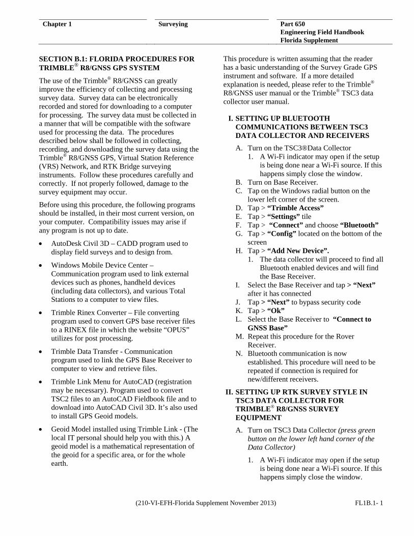
M, and 2.0 M. The maximum height for this setting is 2.0 M. See Figure 1.
2. Insert the push pin into the hole to lock the desired height. Once pin is inserted lock the center leg by tightening the black knob.
B. Place the center leg of the large yellow SECO tripod directly on the Control Point. Adjust the three legs of the tripod to get the tripod level using the level on the control rod. The leg of the SECO tripod that has a brass screw must be tightened with the pinky finger and the thumb to avoid stripping of brass threads.
C. It may be easier to attach cables to the base receiver (base receiver is marked with a “tx” with permanent tape or permanent marker) BEFORE placing the base receiver on top of the SECO tripod. As the tripod can get quite tall if set to the maximum height of 2.0m.
Figure 1: Rover Receiver Tripod
D. Attach the small black antenna to the base receiver
E. Attach base receiver to brass attachment and place on top of the large yellow SECO tripod. Make sure you wiggle the brass piece on top of the tripod to secure it in place and tighten with brass screw underneath the base plate. (Optional base extension may also be used. If using the port 2 cable it will need to be used. It’s 0.25m in length and may be noted in the data collector for height of instrument).
F. Level tripod- (tripod may have to be moved while base receiver was attached).
1. There will be only two legs with loosening grips and one leg with a brass screw. Place one hand on the leg itself, and the other hand on the loosening grip.
2. Squeeze the loosening grip so the leg can freely move.
3. Use other hand to adjust the leg while looking at the leveling bubble.
4. Repeat for the other leg.
5. The third leg will have a brass screw and a black knob. Loosen both screw and black knob, level.
6. Once tripod is level, tighten the last leg of SECO tripod by using the black knob. Use the pinky finger and the thumb to tighten brass screw to avoid stripping the brass threads.
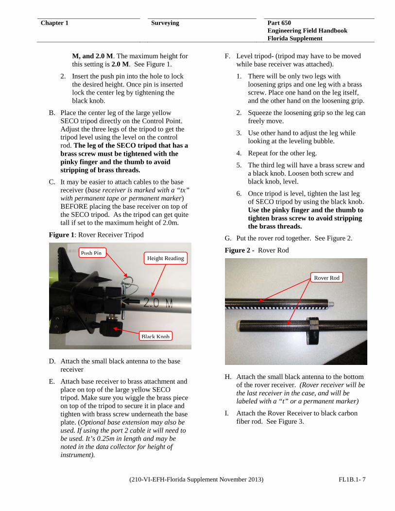
G. Put the rover rod together. See Figure 2.
Figure 2 - Rover Rod
H. Attach the small black antenna to the bottom of the rover receiver. (Rover receiver will be the last receiver in the case, and will be labeled with a “t” or a permanent marker)
I. Attach the Rover Receiver to black carbon fiber rod. See Figure 3.
Rover Rod
Push Pin
Black Knob
Height Reading
(210-VI-EFH-Florida Supplement November 2013) FL1B.1- 7
Chapter 1 Surveying Part 650 Engineering Field Handbook Florida Supplement
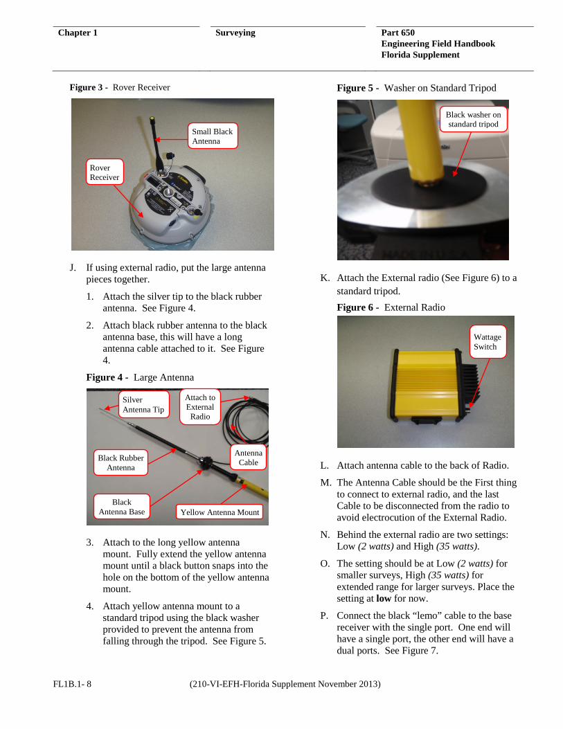
Figure 3 - Rover Receiver
J. If using external radio, put the large antenna pieces together.
1. Attach the silver tip to the black rubber antenna. See Figure 4.
2. Attach black rubber antenna to the black antenna base, this will have a long antenna cable attached to it. See Figure 4.
Figure 4 - Large Antenna
3. Attach to the long yellow antenna mount. Fully extend the yellow antenna mount until a black button snaps into the hole on the bottom of the yellow antenna mount.
4. Attach yellow antenna mount to a standard tripod using the black washer provided to prevent the antenna from falling through the tripod. See Figure 5.
Figure 5 - Washer on Standard Tripod
K. Attach the External radio (See Figure 6) to a standard tripod. Figure 6 - External Radio
L. Attach antenna cable to the back of Radio.
M. The Antenna Cable should be the First thing to connect to external radio, and the last Cable to be disconnected from the radio to avoid electrocution of the External Radio.
N. Behind the external radio are two settings: Low (2 watts) and High (35 watts).
O. The setting should be at Low (2 watts) for smaller surveys, High (35 watts) for extended range for larger surveys. Place the setting at low for now.
P. Connect the black “lemo” cable to the base receiver with the single port. One end will have a single port, the other end will have a dual ports. See Figure 7.
Black washer on standard tripod
Wattage Switch
Small Black Antenna
Rover Receiver
Silver Antenna Tip
Black Rubber Antenna
Black Antenna Base Yellow Antenna Mount
Antenna Cable
Attach to External
Radio
FL1B.1- 8 (210-VI-EFH-Florida Supplement November 2013)
Chapter 1 Surveying Part 650 Engineering Field Handbook Florida Supplement
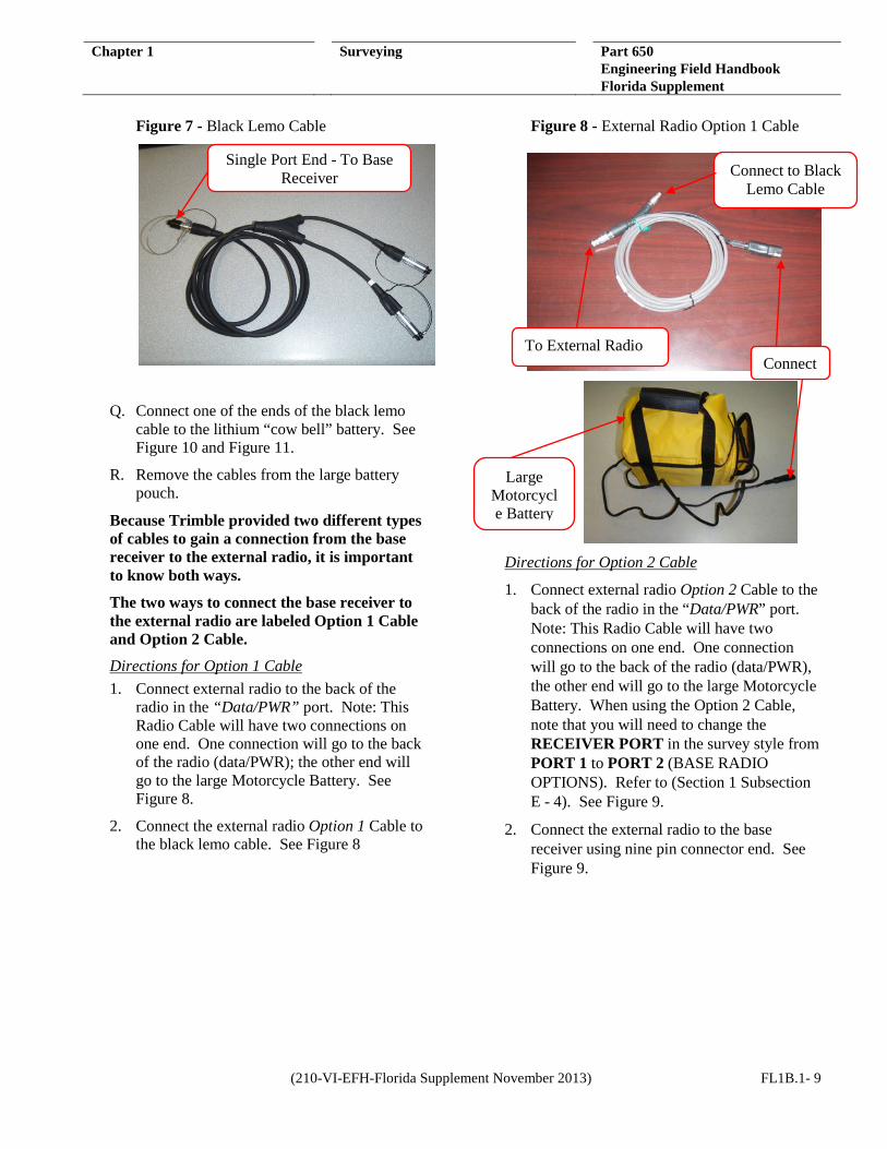
Figure 7 - Black Lemo Cable
Q. Connect one of the ends of the black lemo cable to the lithium “cow bell” battery. See Figure 10 and Figure 11.
R. Remove the cables from the large battery pouch.
Because Trimble provided two different types of cables to gain a connection from the base receiver to the external radio, it is important to know both ways.
The two ways to connect the base receiver to the external radio are labeled Option 1 Cable and Option 2 Cable.
Directions for Option 1 Cable 1. Connect external radio to the back of the
radio in the “Data/PWR” port. Note: This Radio Cable will have two connections on one end. One connection will go to the back of the radio (data/PWR); the other end will go to the large Motorcycle Battery. See Figure 8.
2. Connect the external radio Option 1 Cable to the black lemo cable. See Figure 8
Figure 8 - External Radio Option 1 Cable
Directions for Option 2 Cable
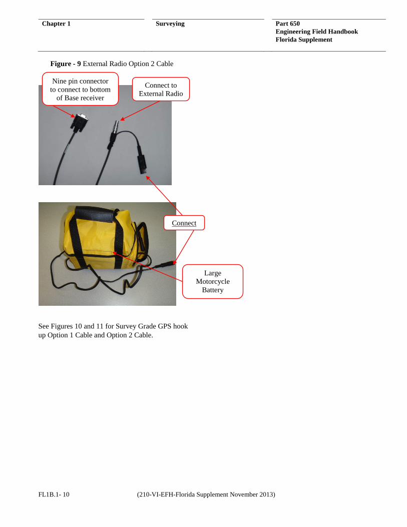
1. Connect external radio Option 2 Cable to the back of the radio in the “Data/PWR” port. Note: This Radio Cable will have two connections on one end. One connection will go to the back of the radio (data/PWR), the other end will go to the large Motorcycle Battery. When using the Option 2 Cable, note that you will need to change the RECEIVER PORT in the survey style from PORT 1 to PORT 2 (BASE RADIO OPTIONS). Refer to (Section 1 Subsection E - 4). See Figure 9.
2. Connect the external radio to the base receiver using nine pin connector end. See Figure 9.
Single Port End - To Base Receiver
Connect
Connect to Black Lemo Cable
To External Radio
Large Motorcycle Battery
(210-VI-EFH-Florida Supplement November 2013) FL1B.1- 9
Chapter 1 Surveying Part 650 Engineering Field Handbook Florida Supplement
Figure - 9 External Radio Option 2 Cable
See Figures 10 and 11 for Survey Grade GPS hook up Option 1 Cable and Option 2 Cable.
Nine pin connector to connect to bottom
of Base receiver
Connect to External Radio
Connect
Large Motorcycle
Battery
FL1B.1- 10 (210-VI-EFH-Florida Supplement November 2013)
Chapter 1 Surveying Part 650 Engineering Field Handbook Florida Supplement
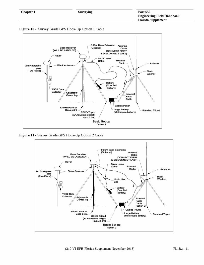
Figure 10 - Survey Grade GPS Hook-Up Option 1 Cable
Figure 11 - Survey Grade GPS Hook-Up Option 2 Cable
(210-VI-EFH-Florida Supplement November 2013) FL1B.1- 11

Chapter 1 Surveying Part 650 Engineering Field Handbook Florida Supplement
VII. SETTING RADIO FREQUENCIES WITH
TRIMBLE ACCESS FOR TSC3
A. Turn on TSC3 Data Collector (press green button on the lower left hand corner of the Data Collector)
1. A Wi-Fi indicator may open if the setup is being done near a Wi-Fi source. If this happens simply close the window.
B. Press the windows icon on-screen or the physical windows button (both located near the bottom left corner of the screen) until the “Trimble Access” icon is visible
C. Tap > “Trimble Access”
D. Tap > “General Survey” tile
E. Tap > “Instrument” tile
F. Tap > “GNSS Functions” tile
G. Tap > “Base Mode” tile
1. Bluetooth will start automatically connecting to the Base Receiver
2. “Radio” tile will be active once the base is connected through Bluetooth
H. Tap “Radio” tile
I. Tap > “Connect”
1. Either set frequency or write it down
2. (411.2500) is the typical frequency used
J. Tap > “Rover Mode” tile
1. Bluetooth will start automatically connecting to rover receiver
2. “Radio” tile will be active once the rover is connected through Bluetooth
K. Tap > “Radio”
L. Tap > “Connect”
Either set frequency to what the Base Radio or the HPB450 radio frequency is to get proper communications.
VIII. STARTING A SURVEY JOB IN THE FIELD
A. Turn on TSC3 Data Collector (press green button on the lower left hand corner of the Data Collector)
1. A Wi-Fi indicator may open if the setup is being done near a Wi-Fi source. If this happens simply close the window.
B. Press the windows icon on-screen or the physical windows button (both located near the bottom left corner of the screen) until the “Trimble Access” icon is visible
C. Tap > “Trimble Access”
D. Tap > “General Survey” tile
E. If the recently created JOB file does not default:
1. Tap > “Jobs”
2. Tap > “Open Jobs”
3. Select JOB to be used
F. Tap > “Measure” tile
G. Select the “Measure Style” to be used on the job
1. If RTK or RTK Internal is to be used select “Start Base Receiver”
2. Bluetooth will automatically connect to the base receiver being used
H. Under “Point Name” tap the little black arrow and select “Key in”
1. If set up on a known monument, enter the coordinates and elevation
2. If not set up on a known monument, select “Here” from the bottom of the screen
I. Set “Point Name” to > “1”
J. Set “Code” to > “CP or CP1”
K. Tap > “Enter”
L. Tap > “Store”
M. Tap > “Start” to start the Base Receiver
N. Base Receiver will start after Reliability is at 100%
O. Tap > “Measure”
P. Select the “Survey Style” to be used on the job
FL1B.1- 12 (210-VI-EFH-Florida Supplement November 2013)
Chapter 1 Surveying Part 650 Engineering Field Handbook Florida Supplement
Q. Tap > “Measure Points”
R. Data Collector will automatically connect to both receivers via Bluetooth
S. For new jobs, ensure that “Method” is set to “Topo Point” and the “Point Name” is set to “1000”
T. For existing jobs, data collector will start with the next point name from the last point stored
U. Start surveying
V. If the VRS survey style is to be used
1. Tap > “Measure Points”
2. Data collector will automatically connect to the Rover Receiver via Bluetooth
IX. ENDING A SURVEY WITH TRIMBLE ACCESS
A. Exit out of “Measuring Points Screen”
B. Tap > “Measure” tile
C. Tap > “End GNSS Survey”
D. Tap > “Yes” to power down receivers
E. Tap > “Exit”
F. Shut down “General Survey” and tap “Yes”
X. SITE ELEVATION CALIBRATION
This procedure will ensure elevation accuracy of benchmarks on project sites when using the survey grade GPS. These procedures assume the user possesses basic knowledge and understanding of surveying techniques to perform a Bench Level Circuit survey.
A. Set a minimum of three benchmarks using wooden stakes or #4 rebar. Set benchmarks at a minimum distance of 200 feet to limit the number of turns.
B. The elevation of the benchmark may be assumed or a known monument (i.e., NGS markers).
C. Draw a small sketch of the site in the fieldbook. Record necessary information about the survey in the fieldbook (i.e., rodman, date, weather, etc.).
D. Perform a Bench Level Circuit survey on all benchmarks (minimum of three (3) and record all measurements for turning points and benchmarks in fieldbook).
E. The survey must close within recommended tolerance as per equation –
0.10𝑓𝑡√𝑀
M= distance in Miles
(i.e., 0.10√0.5 = 0.07ft allowable tolerance) in order for the information to be used for the survey.
If bench level circuit is not in tolerance, record in fieldbook, and rerun bench level circuit survey again until it closes within tolerance.
F. If the Bench Level Circuit Survey was conducted with assumed elevations, a translation will need to be performed. A translation on the site calibration elevations may be conducted using the “Translate Survey Database” tool in Civil 3D. Refer to the Engineers Field Handbook Part 650, Chapter 1, Florida Supplement, Section D for a more detailed explanation.
G. Once the bench level circuit survey is complete begin GPS surveying.
H. Elevation differences between BM should be the same with site calibration elevations and elevations shot with the GPS.
I. Bench Level survey may also need to be rerun if elevations from GPS and previous bench level survey elevations vary more than the allowable tolerance.
J. If survey job takes more than a day, the benchmarks will need to be recorded with the survey grade GPS at the beginning of each day to ensure accuracy of elevations.
XI. DOWNLOADING THE BASE FILES USING TRIMBLE DATA TRANSFER SOFTWARE
This is done to get the base point adjusted by OPUS or post processed by OPUS to get the best results for the survey. Due to this being the newest survey equipment at the present time,
(210-VI-EFH-Florida Supplement November 2013) FL1B.1- 13
Chapter 1 Surveying Part 650 Engineering Field Handbook Florida Supplement
OPUS requires that the T02 file or DAT file be converted to a RINEX file.
A. Connect the base to the computer using the 9 pin cable for port 1 and the other end connects to the base.
B. Open Trimble Data Transfer by going to the Start menu> All Programs> Trimble Data Transfer > Data Transfer.
C. Tap >“Devices” on the right hand side.
D. Tap >“New” on the lower left hand corner of the “Devices” dialog box.
E. Select “Survey Controller” from the list.
F. Select “COM1” for the port and tap “Next”.
G. Give the device a Name- “R8 Base receiver” or something that represents the base receiver.
H. Tap Finish.
I. To connect to R8 Base receiver select the new device and the base receiver in the list. Tap the “Connect” button which is the green plug in button.
J. Will see a new list.
The files are stored in the “Trimble Data” folder. Now you should be able to download these files using Active Sync or place the file on a thumb drive.
XII. USING THE TRIMBLE RINEX CONVERTER
A. Create a folder in which you can place your “T02” R8/GNSS base file or files. (Usually associated with the project file folder).
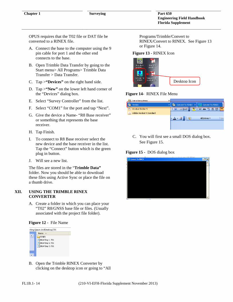
Figure 12 - File Name
B. Open the Trimble RINEX Converter by clicking on the desktop icon or going to “All
Programs/Trimble/Convert to RINEX/Convert to RINEX. See Figure 13 or Figure 14.
Figure 13 - RINEX Icon
Figure 14- RINEX File Menu
C. You will first see a small DOS dialog box. See Figure 15.
Figure 15 - DOS dialog box
Desktop Icon
FL1B.1- 14 (210-VI-EFH-Florida Supplement November 2013)
Chapter 1 Surveying Part 650 Engineering Field Handbook Florida Supplement
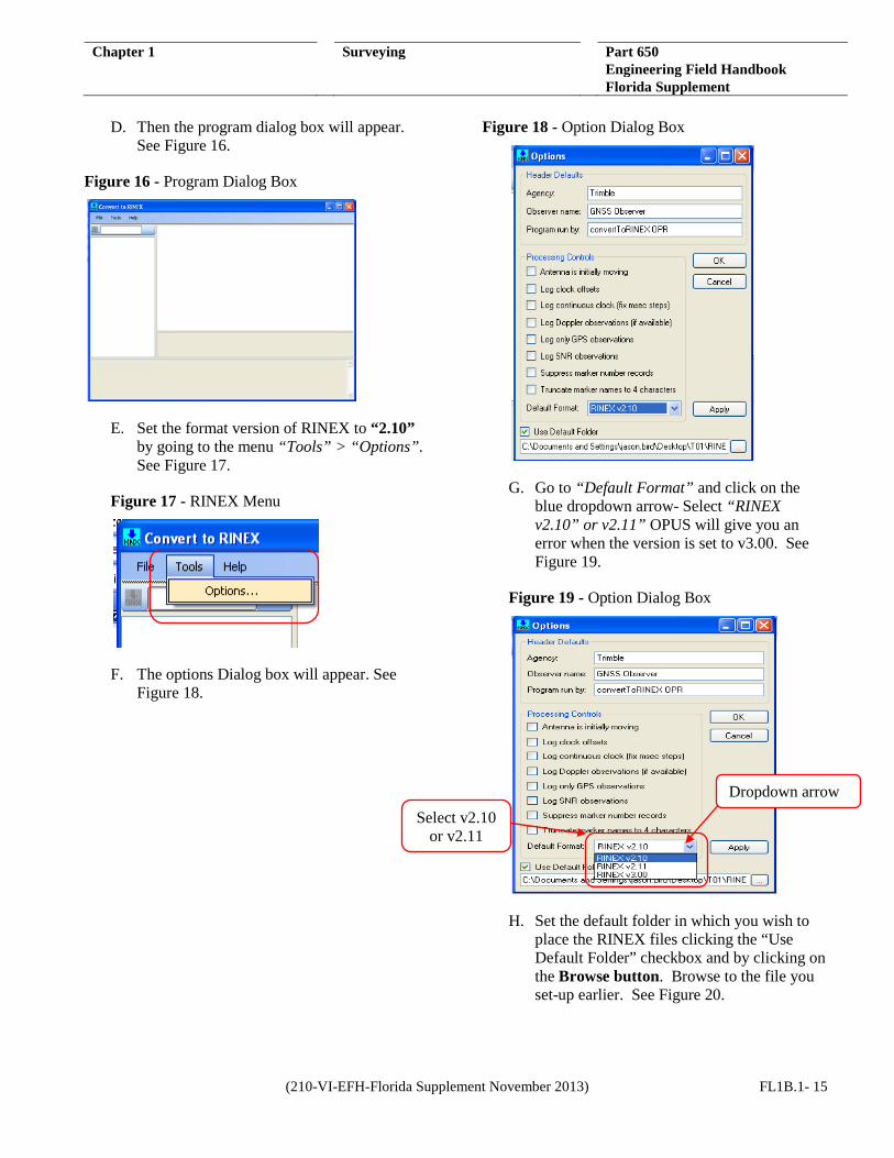
D. Then the program dialog box will appear.
See Figure 16.
Figure 16 - Program Dialog Box
E. Set the format version of RINEX to “2.10” by going to the menu “Tools” > “Options”. See Figure 17.
Figure 17 - RINEX Menu
F. The options Dialog box will appear. See Figure 18.
Figure 18 - Option Dialog Box
G. Go to “Default Format” and click on the blue dropdown arrow- Select “RINEX v2.10” or v2.11” OPUS will give you an error when the version is set to v3.00. See Figure 19.
Figure 19 - Option Dialog Box
H. Set the default folder in which you wish to place the RINEX files clicking the “Use Default Folder” checkbox and by clicking on the Browse button. Browse to the file you set-up earlier. See Figure 20.
Select v2.10 or v2.11
Dropdown arrow
(210-VI-EFH-Florida Supplement November 2013) FL1B.1- 15
Chapter 1 Surveying Part 650 Engineering Field Handbook Florida Supplement
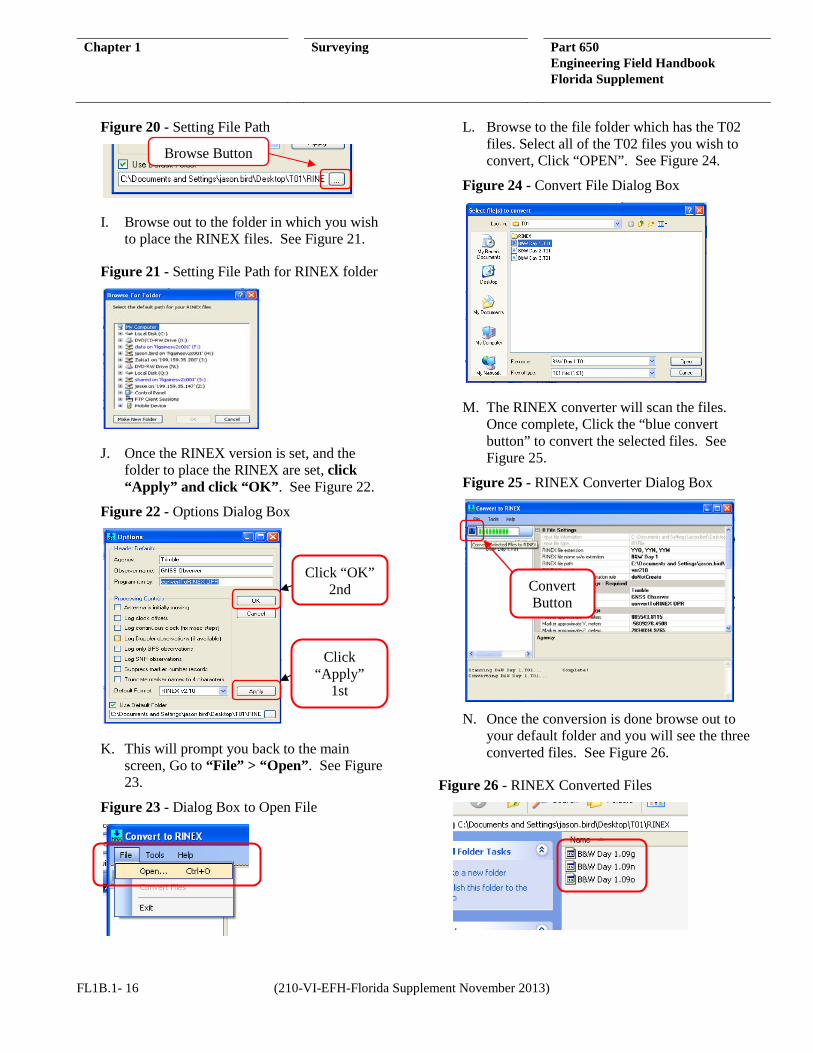
Figure 20 - Setting File Path
I. Browse out to the folder in which you wish to place the RINEX files. See Figure 21.
Figure 21 - Setting File Path for RINEX folder
J. Once the RINEX version is set, and the folder to place the RINEX are set, click “Apply” and click “OK”. See Figure 22.
Figure 22 - Options Dialog Box
K. This will prompt you back to the main screen, Go to “File” > “Open”. See Figure 23.
Figure 23 - Dialog Box to Open File
L. Browse to the file folder which has the T02 files. Select all of the T02 files you wish to convert, Click “OPEN”. See Figure 24.
Figure 24 - Convert File Dialog Box
M. The RINEX converter will scan the files. Once complete, Click the “blue convert button” to convert the selected files. See Figure 25.
Figure 25 - RINEX Converter Dialog Box
N. Once the conversion is done browse out to
your default folder and you will see the three converted files. See Figure 26.
Figure 26 - RINEX Converted Files
Browse Button
Click “OK” 2nd
Click “Apply”
1st
Convert Button
FL1B.1- 16 (210-VI-EFH-Florida Supplement November 2013)
Chapter 1 Surveying Part 650 Engineering Field Handbook Florida Supplement
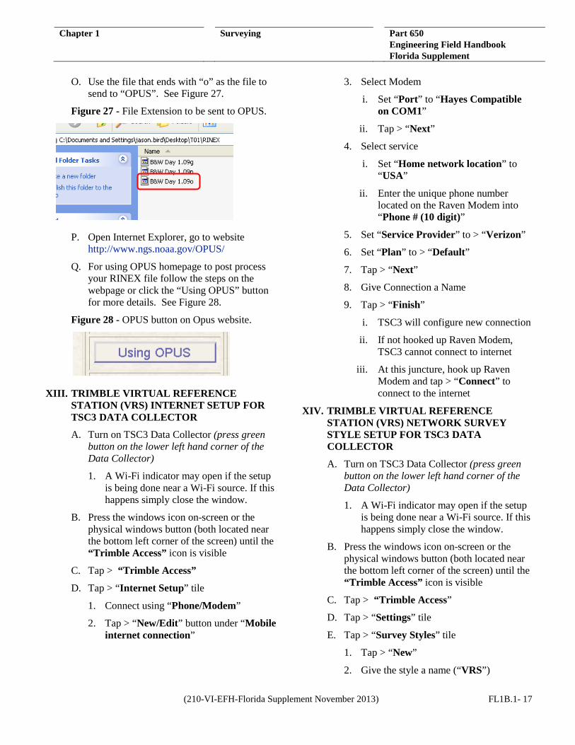
O. Use the file that ends with “o” as the file to
send to “OPUS”. See Figure 27.
Figure 27 - File Extension to be sent to OPUS.
P. Open Internet Explorer, go to website http://www.ngs.noaa.gov/OPUS/
Q. For using OPUS homepage to post process your RINEX file follow the steps on the webpage or click the “Using OPUS” button for more details. See Figure 28.
Figure 28 - OPUS button on Opus website.
XIII. TRIMBLE VIRTUAL REFERENCE STATION (VRS) INTERNET SETUP FOR TSC3 DATA COLLECTOR
A. Turn on TSC3 Data Collector (press green button on the lower left hand corner of the Data Collector)
1. A Wi-Fi indicator may open if the setup is being done near a Wi-Fi source. If this happens simply close the window.
B. Press the windows icon on-screen or the physical windows button (both located near the bottom left corner of the screen) until the “Trimble Access” icon is visible
C. Tap > “Trimble Access”
D. Tap > “Internet Setup” tile
1. Connect using “Phone/Modem”
2. Tap > “New/Edit” button under “Mobile internet connection”
3. Select Modem
i. Set “Port” to “Hayes Compatible on COM1”
ii. Tap > “Next”
4. Select service
i. Set “Home network location” to “USA”
ii. Enter the unique phone number located on the Raven Modem into “Phone # (10 digit)”
5. Set “Service Provider” to > “Verizon”
6. Set “Plan” to > “Default”
7. Tap > “Next”
8. Give Connection a Name
9. Tap > “Finish”
i. TSC3 will configure new connection
ii. If not hooked up Raven Modem, TSC3 cannot connect to internet
iii. At this juncture, hook up Raven Modem and tap > “Connect” to connect to the internet
XIV. TRIMBLE VIRTUAL REFERENCE STATION (VRS) NETWORK SURVEY STYLE SETUP FOR TSC3 DATA COLLECTOR
A. Turn on TSC3 Data Collector (press green button on the lower left hand corner of the Data Collector)
1. A Wi-Fi indicator may open if the setup is being done near a Wi-Fi source. If this happens simply close the window.
B. Press the windows icon on-screen or the physical windows button (both located near the bottom left corner of the screen) until the “Trimble Access” icon is visible
C. Tap > “Trimble Access”
D. Tap > “Settings” tile
E. Tap > “Survey Styles” tile
1. Tap > “New”
2. Give the style a name (“VRS”)
(210-VI-EFH-Florida Supplement November 2013) FL1B.1- 17

Chapter 1 Surveying Part 650 Engineering Field Handbook Florida Supplement
3. Set “Style Type” to > “GNSS”
4. Tap > “Accept”
F. Tap > “Rover Options” on the resulting screen
1. Choose RTK for the “Survey type”
i. Note: The RTK & Infill option allows the base receiver to save a T02 file in the receiver for OPUS Solutions. Since we have VRS corrections and other post processing options there is no need for OPUS Solutions.
2. Set the “Broadcast format” to > “VRS (RTCM)”
3. Set “Store Points as” to > “Vector”
4. Set the “Elevation mask” to > “10o”
5. Set the “PDOP mask” to > “6.0”
6. Tap the page progression icon
7. Set the antenna “Type” to > “R8 GNSS/SPS88x”
8. Set “Measured to” to > “Bottom of antenna mount”
9. Set the “Antenna height” to > “2.0m”
i. Note: This is the default height for the carbon fiber survey rods. If a different rod is being used then a different value will need to be used.
10. Leave the “Serial number” field blank
11. Tap the page progression icon
12. Ensure that, at the bottom of the screen, “Use L2e” says “Yes” and the “GPS L2C” and “GLONASS” boxes are checked
13. Tap > “Accept”
G. Tap > “Rover Radio” on the resulting screen
1. Set the “Type” to > “Internet Connection”
2. Set the “Route through controller” to > “Yes”
3. Set the “Route through controller” to > “Yes”
4. Check the “Prompt for GNSS contact” box
5. Tap > “Accept”
H. Tap > “Topo point” on the resulting screen
1. Set the “Auto point step size” to > “1”
2. Choose > “QC 1 & QC 2” for the “Quality control”
3. Check the box for the “Auto store point” option
i. Note: This option is not necessary and is left to the discretion of the user.
ii. With this option enabled, points will automatically store are they are measured.
4. Set the “Occupation time” to > “0m5s”
5. Set the “Number of measurements” to > “3”
6. Check “Auto Tolerance” and “Store RTK initialized only” boxes
7. Tap the page progression icon
8. Uncheck the “Auto Abandon” box
9. Tap > “Accept”
I. Scroll to “Observed Control Point”
1. Check the “Auto Store Point” box
2. Set RTK number of measurements to > “50”
3. Check the “Precision: Auto Tolerance” box
4. Tap the page progression icon
5. Uncheck the “Auto Abandon” box
6. Leave Postprocess defaults
7. Tap > “Accept”
8. Tap > “Store”
FL1B.1- 18 (210-VI-EFH-Florida Supplement November 2013)

Chapter 1 Surveying Part 650 Engineering Field Handbook Florida Supplement
XV. IN THE FIELD WITH THE VRS
NETWORK
A. Connect the Modem to the battery that was supplied, (Self-explanatory). See Figure 29.
Figure 29 - Modem to Battery Connection
B. Connect the small antenna to the modem that was supplied.
C. Put together Rover rod with Rover receiver.
D. Connect the modem to the TSC3 Data Collector using the cream-colored communications cable (one end FEMALE, the other end is MALE).
E. Attach the VRS modem and TSC3 data collector to the Rover Rod for a complete set-up. See figure 30.
Figure 30 - Complete set-up of VRS Network
F. Turn on TSC3 data collector.
G. Set-up new job or open existing job.
H. Turn on Rover receiver.
I. Using TSC3, blue tooth to Rover Receiver.
J. Once connected go to the Survey icon.
K. Select the VRS Network survey style.
L. Select Start Survey.
M. Select the Dial Profile from the list; it will be the only one available “VRS Now”.
N. Tap “Accept”.
O. The screen will say “Switching Modem into Command Mode”.
P. Network Log on screen will appear:
1. User name: NRCS Supplied Username
2. Password: NRCS Supplied Password
3. Domain: Leave Blank
Q. The modem will establish internet connection and a list of base stations will appear.
R. Select a “Base Station” from the list. There are multiple base stations, choose any station to create a connection.
S. An open connection scroll bar will appear. The instrument will attempt to communicate with satellites. The survey will begin once a connection has been established.
T. Initialization will be gained.
U. Select the “Survey” icon
V. Select “Measure Points”
W. Select proper field code and begin field survey.
X. To end Survey Tap > “ESC”
Y. Tap > “Survey”
Z. Tap > “End GPS Survey”
AA. Turn off rover receiver.
BB. Shut down TSC3 data collector and Pack up Equipment.
(210-VI-EFH-Florida Supplement November 2013) FL1B.1- 19

Chapter 1 Surveying Part 650 Engineering Field Handbook Florida Supplement
XVI. R8/GNSS RTK BRIDGE SURVEY STYLE
SET UP FOR TSC3 DATA COLLECTOR
A. Turn on TSC3 Data Collector (press green button on the lower left hand corner of the Data Collector)
A Wi-Fi indicator may open if the setup is being done near a Wi-Fi source. If this happens simply close the window.
B. Press the windows icon on-screen or the physical windows button (both located near the bottom left corner of the screen) until the “Trimble Access” icon is visible
C. Tap > “Trimble Access”
D. Tap > “Settings” tile
E. Tap >”Survey Styles” tile
1. Tap > “New”
2. Give the style a name (“Bridge”)
3. Set “Style Type” to > “GNSS”
4. Tap > “Accept”
F. Tap > “Rover Options” on the resulting screen
1. Choose RTK for the “Survey type”
i. Note: The RTK & Infill option allows the base receiver to save a T02 file in the receiver for OPUS Solutions. Since we have VRS corrections and other post processing options there is no need for OPUS Solutions.
2. Set the “Broadcast format” to > “VRS (CMR)”
3. Set “Use Station Index” to > “Any”
4. Check “Prompt Station index” box
5. Tap the page progression icon
6. Set the “Satellite differential” to > “Off”
7. Set the “Elevation mask” to > “10o”
8. Set the “PDOP mask” to > “6.0”
9. Set the antenna “Type” to > “R8 GNSS/SPS88x”
10. Tap the page progression icon
11. Set “Measured to” to > “Bottom of antenna mount”
12. Set the “Antenna height” to > “2.0m”
Note: This is the default height for the carbon fiber survey rods. If a different rod is being used then a different value will need to be used.
13. Leave the “Serial number” field blank
14. Ensure that, at the bottom of the screen, “Use L2e” says “Yes” and the “GPS L2C” box is checked
15. Tap the page progression icon
16. Ensure that the “GPS L5”, “GLONASS”, “Galileo”, and “QZSS” boxes are checked
17. Tap > “Accept”
G. Tap > “Rover Radio” on the resulting screen
1. Set the “Type” to > “Receiver Internal”
2. Set the “Method” to > “Trimble 450/900”
3. Tap > “Accept”
H. Tap > “Topo point” on the resulting screen
1. Set the “Auto point step size” to > “1”
2. Choose > “QC 1 & QC 2” for the “Quality control”
3. Check the box for the “Auto store point” option
i. Note: This option is not necessary and is left to the discretion of the user.
ii. With this option enabled, points will automatically store are they are measured.
4. Set the “Occupation time” to > “0m5s”
FL1B.1- 20 (210-VI-EFH-Florida Supplement November 2013)

Chapter 1 Surveying Part 650 Engineering Field Handbook Florida Supplement
5. Set the “Number of measurements” to
> “3”
6. Check “Auto Tolerance” and “Store RTK initialized only” boxes
7. Tap the page progression icon
8. Uncheck the “Auto Abandon” box
9. Tap > “Accept”
I. Scroll to “Observed Control Point”
1. Check the “Auto Store Point” box
2. Set RTK number of measurements to > “50”
3. Check the “Precision: Auto Tolerance” box
4. Tap the page progression icon
5. Uncheck the “Auto Abandon” box
6. Set “Time for 4 SVs” to “10m0s”
7. Set “Time for 5 SVs” to “8m0s”
8. Set “Time for 6+ SVs” to “5m0s”
9. Tap > “Accept”
J. Tap > “Store”
(210-VI-EFH-Florida Supplement November 2013) FL1B.1- 21

Chapter 1 Surveying Part 650 Engineering Field Handbook Florida Supplement
THIS PAGE INTENTIONALLY LEFT BLANK
FL1B.1- 22 (210-VI-EFH-Florida Supplement November 2013)


![OdakyuAndroid t Google play] Wi-Fi Android ios t App Store] Wi-Fi [App Store] [iPhone Profile) Wi-Fi # —E Odakyu Odakyu Free Wi-Fi Android [Google play] WI-Fi Android [App Wi-Fi](https://img.pdfslide.net/doc/110x75/5fcc31f69b77e950d81a9828/android-t-google-play-wi-fi-android-ios-t-app-store-wi-fi-app-store-iphone.jpg)


![2 Pilih [Wi-Fi function (Fungsi Wi-Fi)]](https://img.pdfslide.net/doc/110x75/587653b01a28ab135e8b9be3/2-pilih-wi-fi-function-fungsi-wi-fi.jpg)