Embed Size (px)
Citation preview
(2)
CHAPTER1:THECONCEPTOFSTRESS
IntroductiontoMechanics(Strength)ofMaterials:Objectives
Themainobjectiveofthestudyofthemechanicsofmaterialsistoinvestigatethebehaviourofsolid
bodiessubjectedtovarioustypesofloading.Weaimtodeterminewhetherornotasolidbodycan
withstandtheappliedloadstoit.Anunderstandingofmechanicalbehaviourisessentialforthesafe
designofalltypesofstructures.Thesolidbodiesconsideredinthiscourseincludebarswithaxial
loads,shafts intorsion,andbeamsinbending. Inthiscourseonlysolidstructureswithsimplistic
geometriessuchasbodieswithcircularorsquarecrosssectionsareconsidered.
Thedifferenceofthestudyof“Statics”with“Mechanicsofmaterials”isthatin“Statics”wesimply
aimtodetermine internal loadsthatastructureundergoesbutwedonot investigatewhetheror
not the structure can withstand the applied loads to it. In this course, however, we not only
determineifthestructurecanwithstandtheappliedloadsornotbutweestimatethedeformation
of the structureunder the applied loads too.Determiningdeformations is a very important step
towardthesafedesignofalltypesofstructures(TurbinefailureofflightQantas32,A380).
ConceptofStress(NormalStress)
“Force” isnotanappropriatequantity todescribe the toleranceofmaterials.Forexampleasteel
bar with 1 mm2 cross sectional area can withstand very small tensile or compressive forces
comparedtothesamesteelbarhavingacrosssectionalareaof100mm2.Therefore,aquantityis
definedwhichdoesnotdependonthesizeofsamplebar;forcedividedbycrosssectionalarea:
: :
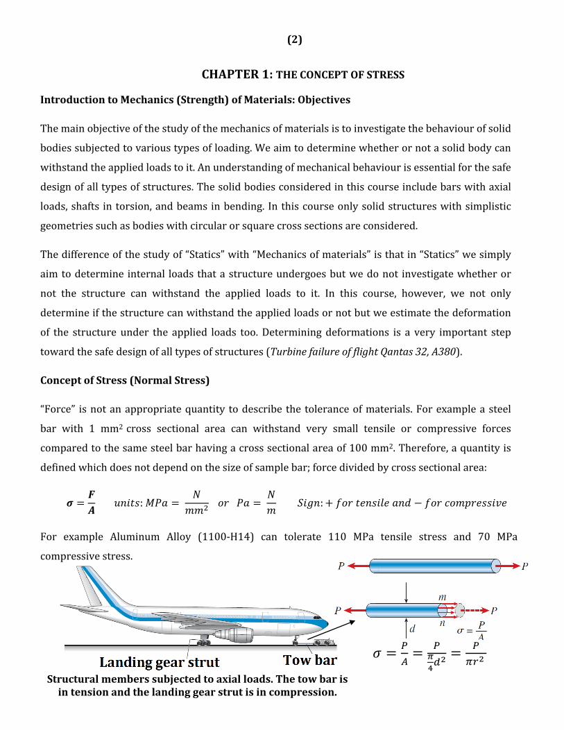
For example Aluminum Alloy (1100‐H14) can tolerate 110 MPa tensile stress and 70 MPa
compressivestress.
Structuralmemberssubjectedtoaxialloads.Thetowbarisintensionandthelandinggearstrutisincompression.
(3)
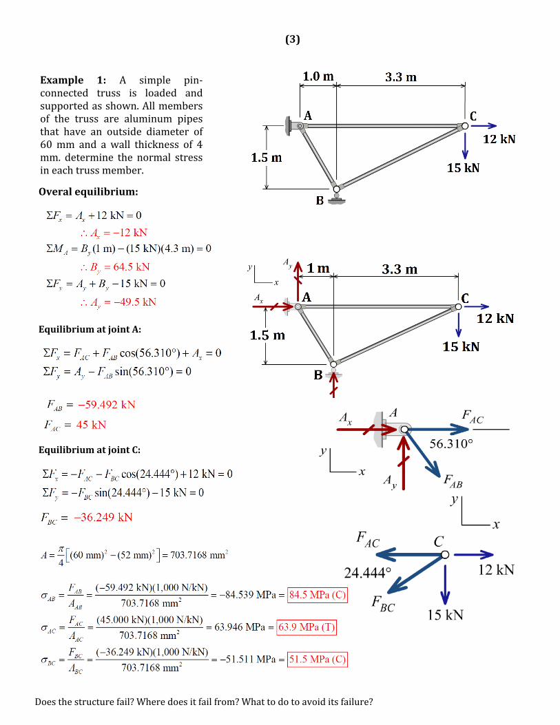
Example 1: A simple pin‐connected truss is loaded andsupportedasshown.Allmembersof the truss are aluminum pipesthat have an outside diameter of60mm and awall thickness of 4mm. determine the normal stressineachtrussmember.
Overalequilibrium:
EquilibriumatjointA:
EquilibriumatjointC:
Doesthestructurefail?Wheredoesitfailfrom?Whattodotoavoiditsfailure?
(4)
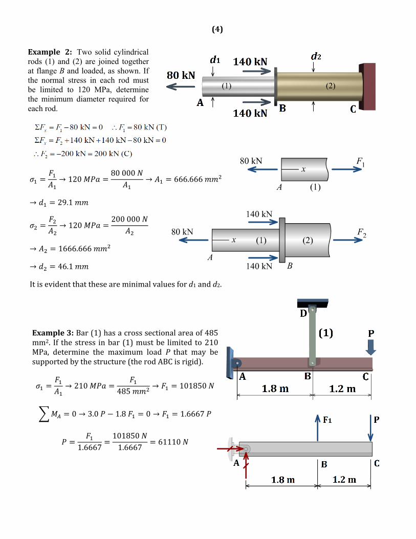
Example 2: Two solid cylindrical rods (1) and (2) are joined together at flange B and loaded, as shown. If the normal stress in each rod must be limited to 120 MPa, determine the minimum diameter required for each rod.
→ 12080000
→ 666.666
→ 29.1
→ 120200000
→ 1666.666
→ 46.1
Itisevidentthattheseareminimalvaluesford1andd2.
Example3:Bar(1)hasacrosssectionalareaof485mm2. If thestress inbar (1)mustbe limited to210MPa, determine the maximum load P that may besupportedbythestructure(therodABCisrigid).
→ 210485
→ 101850
0 → 3.0 1.8 0 → 1.6667
1.66671018501.6667
61110
(5)
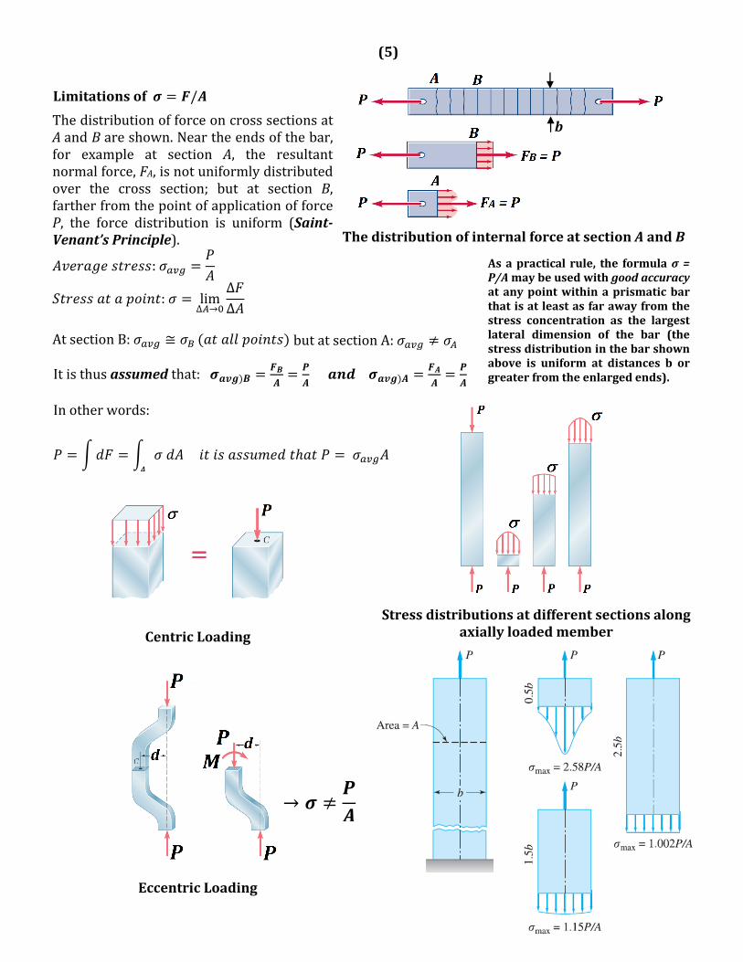
Limitationsof /
ThedistributionofinternalforceatsectionAandB
ThedistributionofforceoncrosssectionsatAandBareshown.Neartheendsofthebar,for example at section A, the resultantnormalforce,FA,isnotuniformlydistributedover the cross section; but at section B,fartherfromthepointofapplicationofforceP, the force distribution is uniform (Saint‐Venant’sPrinciple).
:
: lim∆ →
∆∆
AtsectionB: ≅ butatsectionA:
Itisthusassumedthat:
Inotherwords:
Stressdistributionsatdifferentsectionsalong
axiallyloadedmember
CentricLoading
EccentricLoading
→
Asapracticalrule, the formulaσ=P/Amaybeusedwithgoodaccuracyatanypointwithinaprismaticbarthatisatleastasfarawayfromthestress concentration as the largestlateral dimension of the bar (thestressdistributioninthebarshownabove is uniform at distances b orgreaterfromtheenlargedends).
b
(6)
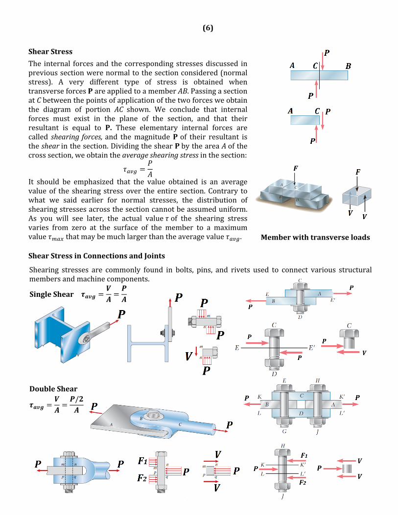
ShearStress
The internal forcesand the corresponding stressesdiscussed inprevioussectionwerenormaltothesectionconsidered(normalstress). A very different type of stress is obtained whentransverseforcesPareappliedtoamemberAB.PassingasectionatCbetweenthepointsofapplicationofthetwoforcesweobtainthe diagram of portion AC shown. We conclude that internalforces must exist in the plane of the section, and that theirresultant is equal to P. These elementary internal forces arecalled shearingforces,and themagnitudePof their resultant istheshearinthesection.DividingtheshearPbytheareaAofthecrosssection,weobtaintheaverageshearingstressinthesection:
It should be emphasized that the value obtained is an averagevalueof the shearing stressover the entire section.Contrary towhat we said earlier for normal stresses, the distribution ofshearingstressesacrossthesectioncannotbeassumeduniform.As you will see later, the actual value of the shearing stressvaries from zero at the surface of the member to a maximumvalue thatmaybemuchlargerthantheaveragevalue .ShearStressinConnectionsandJoints
Memberwithtransverseloads
Shearing stresses are commonly found in bolts, pins, and rivets used to connect various structuralmembersandmachinecomponents.
SingleShear
DoubleShear/
(7)
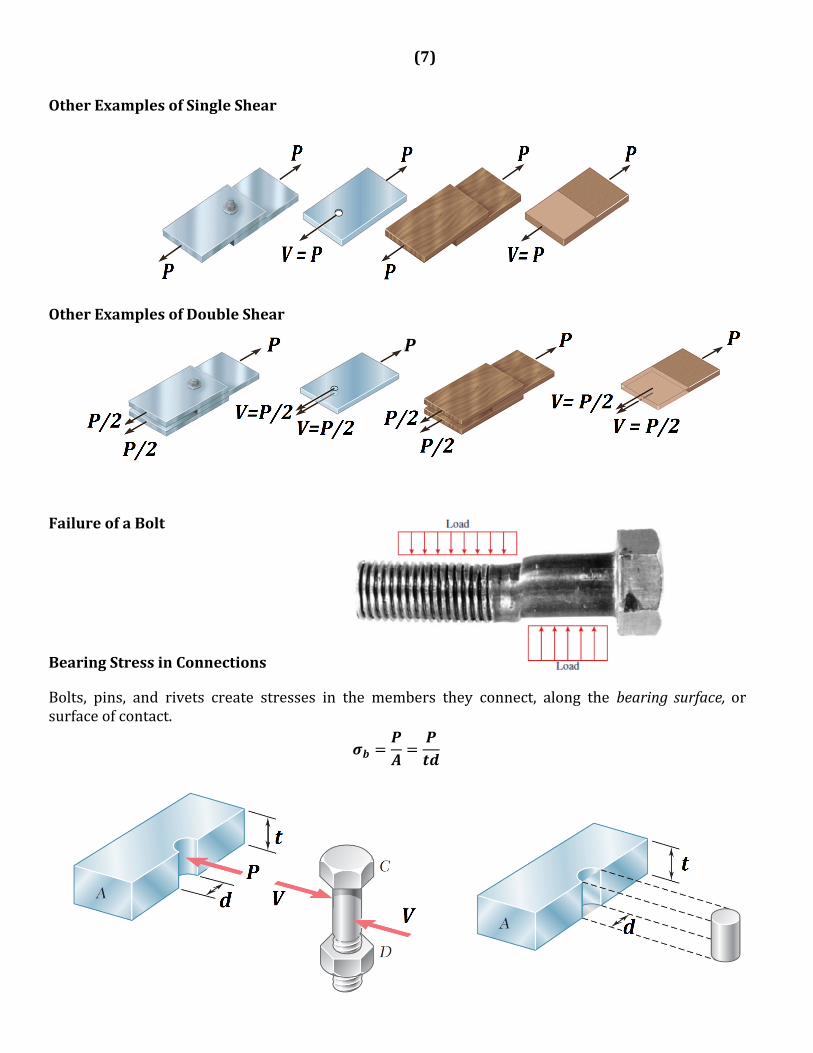
OtherExamplesofSingleShear
OtherExamplesofDoubleShear
FailureofaBolt
BearingStressinConnections
Bolts, pins, and rivets create stresses in the members they connect, along the bearing surface,orsurfaceofcontact.
P
(8)
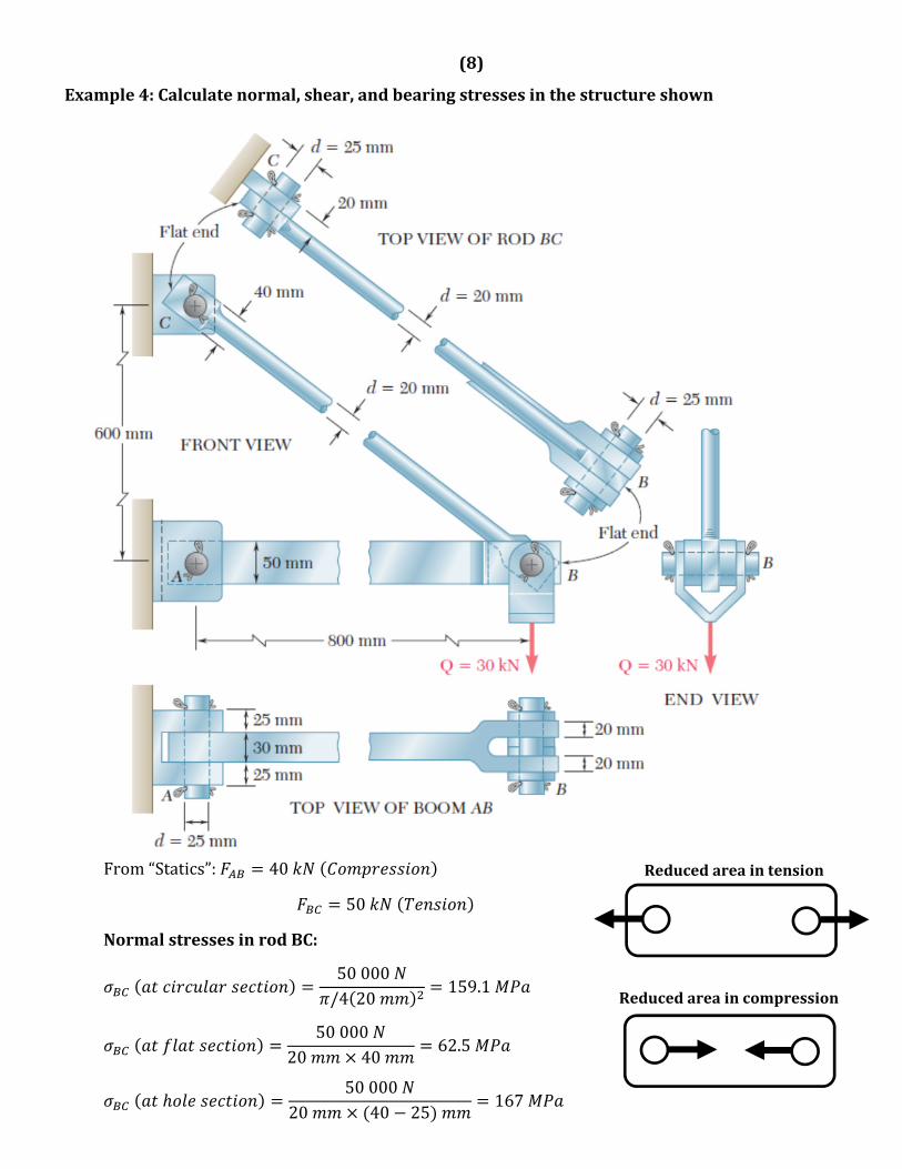
Example4:Calculatenormal,shear,andbearingstressesinthestructureshown
From“Statics”: 40
50
NormalstressesinrodBC:
50000/4 20
159.1
50000
20 4062.5
50000
20 40 25167
Reducedareaintension
Reducedareaincompression
(9)
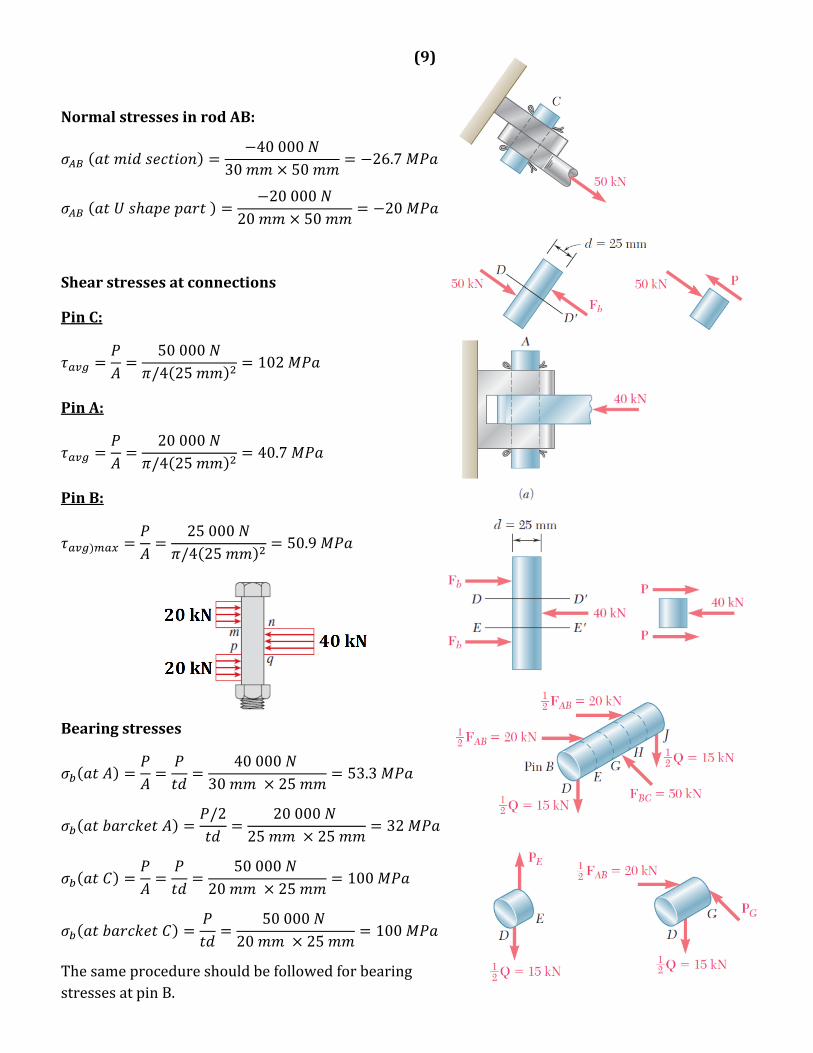
NormalstressesinrodAB:
40000
30 5026.7
20000
20 5020
Shearstressesatconnections
PinC:
50000/4 25
102
PinA:
20000/4 25
40.7
PinB:
25000/4 25
50.9
Bearingstresses
40000
30 2553.3
/2 20000
25 2532
50000
20 25100
50000
20 25100
ThesameprocedureshouldbefollowedforbearingstressesatpinB.
(10)
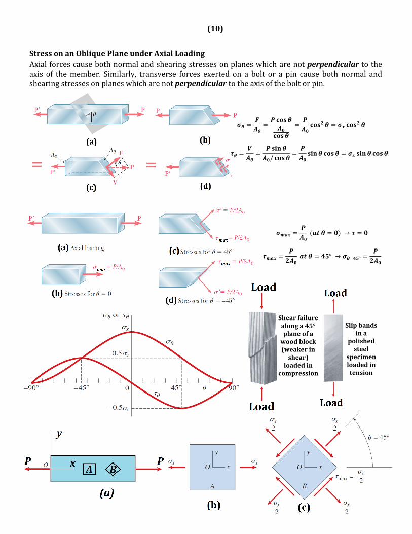
StressonanObliquePlaneunderAxialLoadingAxial forcescausebothnormalandshearingstressesonplaneswhicharenotperpendiculartotheaxis of themember. Similarly, transverse forces exerted on a bolt or a pin cause both normal andshearingstressesonplaneswhicharenotperpendiculartotheaxisoftheboltorpin.
/
→
° → °
Shearfailurealonga45°planeofawoodblock(weakerinshear)loadedin
compression
Slipbandsina
polishedsteel
specimenloadedintension
(11)
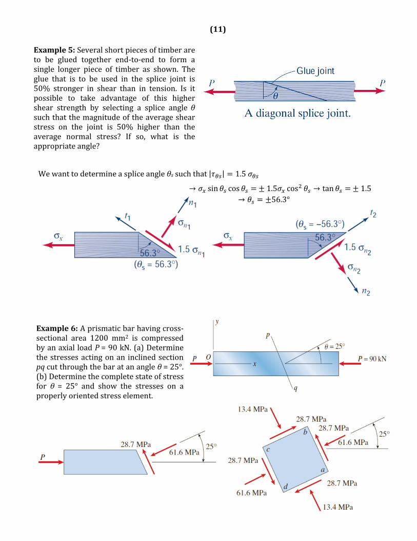
Example5:Severalshortpiecesoftimberareto be glued together end‐to‐end to form asingle longer piece of timber as shown. Theglue that is to be used in the splice joint is50% stronger in shear than in tension. Is itpossible to take advantage of this highershear strength by selecting a splice angle θsuchthatthemagnitudeoftheaverageshearstress on the joint is 50% higher than theaverage normal stress? If so, what is theappropriateangle?
Wewanttodetermineaspliceangleθs suchthat| | 1.5
→ sin cos 1.5 cos → tan 1.5→ 56.3°
Example6:Aprismaticbarhavingcross‐sectional area 1200 mm2 is compressedbyanaxialloadP=90kN.(a)Determinethestressesactingonan inclinedsectionpqcutthroughthebaratanangleθ=25°.(b)Determinethecompletestateofstressfor θ= 25° and show the stresses on aproperlyorientedstresselement.
(12)
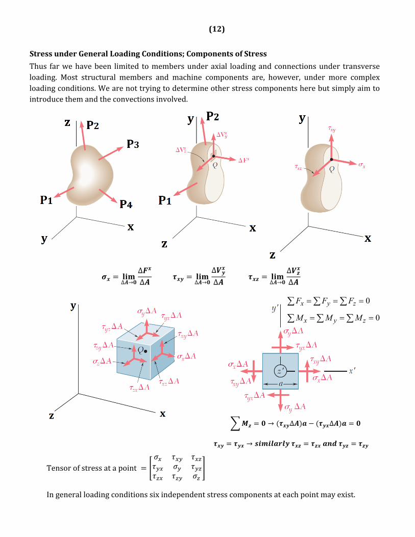
StressunderGeneralLoadingConditions;ComponentsofStress
Thus farwehavebeen limited tomembersunderaxial loadingandconnectionsunder transverseloading. Most structural members and machine components are, however, under more complexloadingconditions.Wearenottryingtodetermineotherstresscomponentsherebutsimplyaimtointroducethemandtheconvectionsinvolved.
∆ →
∆∆
∆ →
∆∆ ∆ →
∆∆
0
0
zyx
zyx
MMM
FFF
→ ∆ ∆
→
Tensorofstressatapoint
Ingeneralloadingconditionssixindependentstresscomponentsateachpointmayexist.
(13)
DesignConsiderations
(1) UltimateStrengthofaMaterial
Animportantelementtobeconsideredbyadesignerishowthematerialthathasbeenselectedwillbehaveunderaload.Foragivenmaterial,thisisdeterminedbyperformingspecifictestsonprepared samples of thematerial. For example, a test specimen of steelmay be prepared andplacedinalaboratorytestingmachinetobesubjectedtoaknowncentricaxialtensileforce,asitwillbedescribedlater.Asthemagnitudeoftheforceisincreased,variouschangesinthespecimenaremeasured, for example, changes in its length and its diameter. Eventually the largest forcewhichmaybeappliedtothespecimenisreached,andthespecimenbreaks.Thislargestforceiscalled the ultimate load for the test specimen and is denoted by PU. Since the applied load iscentric,wemaydividetheultimateloadbytheoriginalcross‐sectionalareaoftherodtoobtaintheultimatenormalstressofthematerialused.Thisstressisalsoknownastheultimatestrengthintensionofthematerial.Severaltestproceduresareavailabletodeterminetheultimateshearingstress,orultimatestrengthinshear,ofamaterial(willbeexplainedlateron).
(2) FactorofSafety
Themaximum load thata structuralmemberoramachine componentwillbeallowed tocarryundernormalconditionsofutilizationisconsiderablysmallerthantheultimateload.Thissmallerloadisreferredtoastheallowableload.Thus,onlyafractionoftheultimate‐loadcapacityofthememberisutilizedwhentheallowableloadisapplied.Theremainingportionoftheload‐carryingcapacityofthememberiskeptinreservetoassureitssafeperformance.Theratiooftheultimateloadtotheallowableloadisusedtodefinethefactorofsafety:
. .
Ofcourse,thefactorofsafetymustbegreaterthan1.0iffailureistobeavoided.Dependinguponthecircumstances,factorsofsafetyfromslightlyabove1.0toasmuchas10areused.Theuseofasmallvalueoffactorofsafety(e.g.,FS=1.1)is justifiedonlywhenit ispossible,byanalysisandtesting, to sufficientlyminimize uncertainties, andwhen there is no likelihood that failurewillresultinunacceptablecircumstancessuchasseriouspersonalinjuryordeath.Ontheotherhand,itisundesirabletouseafactorofsafetythatisunnecessarilylarge(e.g.,FS=3),sincethatwouldlead to excess structuralweight,which, in turn, entails excess initial costs and operating costs.Sincethechoiceofavalueoffactorofsafetyhassuchimportanteconomicandlegalimplications,designspecifications,includingtherelevantfactor(s)ofsafetytobeused,conformtodesigncodesorotherstandardsdevelopedbygroupsofexperiencedengineers inengineeringsocietiesor invariousgovernmentagencies.
(14)
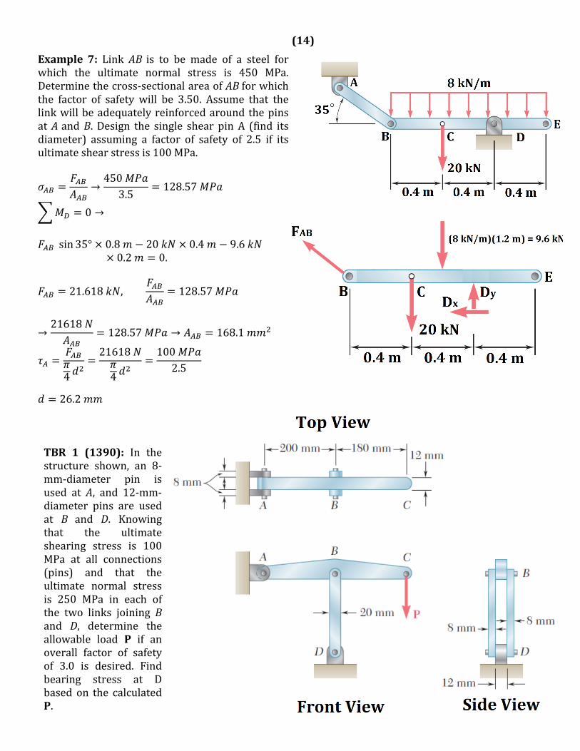
Example 7: Link AB is to be made of a steel forwhich the ultimate normal stress is 450 MPa.Determinethecross‐sectionalareaofABforwhichthe factor of safety will be 3.50. Assume that thelinkwillbeadequatelyreinforcedaroundthepinsatAandB. Design the single shear pinA (find itsdiameter) assuming a factor of safety of 2.5 if itsultimateshearstressis100MPa.
→450
3.5128.57
0 →
sin 35° 0.8 20 0.4 9.6
0.2 0.
21.618 , 128.57
→21618
128.57 → 168.1
4
21618
4
1002.5
26.2
TBR 1 (1390): In thestructure shown, an 8‐mm‐diameter pin isused at A, and 12‐mm‐diameter pins are usedat B and D. Knowingthat the ultimateshearing stress is 100MPa at all connections(pins) and that theultimate normal stressis 250 MPa in each ofthe two links joining Band D, determine theallowable load P if anoverall factor of safetyof 3.0 is desired. Findbearing stress at Dbased on the calculatedP.
(15)
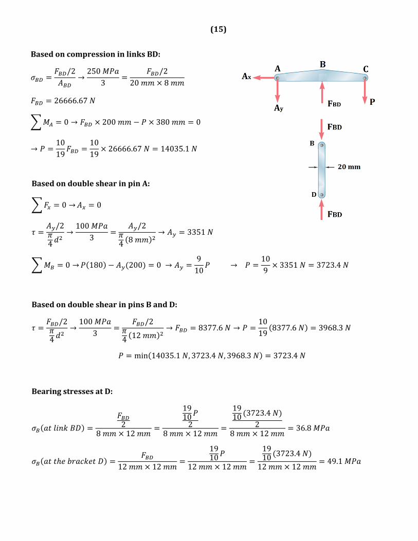
BasedoncompressioninlinksBD:
/2→250
3/2
20 8
26666.67
0 → 200 380 0
→1019
1019
26666.67 14035.1
BasedondoubleshearinpinA:
0 → 0
/2
4→100
3/2
4 8→ 3351
0 → 180 200 0 →910
→ 109
3351 3723.4
BasedondoubleshearinpinsBandD:
/2
4→100
3/2
4 12→ 8377.6 →
1019
8377.6 3968.3
min 14035.1 , 3723.4 , 3968.3 3723.4
BearingstressesatD:
28 12
19102
8 12
1910 3723.4
28 12
36.8
12 12
1910
12 12
1910 3723.4
12 1249.1
(16)
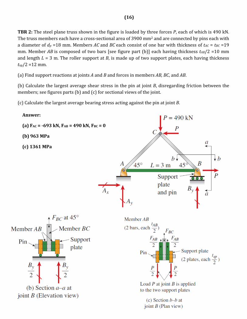
TBR2:ThesteelplanetrussshowninthefigureisloadedbythreeforcesP,eachofwhichis490kN.Thetrussmemberseachhaveacross‐sectionalareaof3900mm2andareconnectedbypinseachwithadiameterofdp=18mm.MembersACandBCeachconsistofonebarwiththicknessoftAC=tBC=19mm.MemberABiscomposedof twobars [see figurepart (b)]eachhaving thickness tAB/2=10mmandlengthL=3m.TherollersupportatB, ismadeupoftwosupportplates,eachhavingthicknesstsp/2=12mm.
(a)FindsupportreactionsatjointsAandBandforcesinmembersAB,BC,andAB.
(b)Calculatethelargestaverageshearstressinthepinat jointB,disregardingfrictionbetweenthemembers;seefiguresparts(b)and(c)forsectionalviewsofthejoint.
(c)CalculatethelargestaveragebearingstressactingagainstthepinatjointB.
Answer:
(a)FAC=‐693kN,FAB=490kN,FBC=0
(b)963MPa
(c)1361MPa
(17)
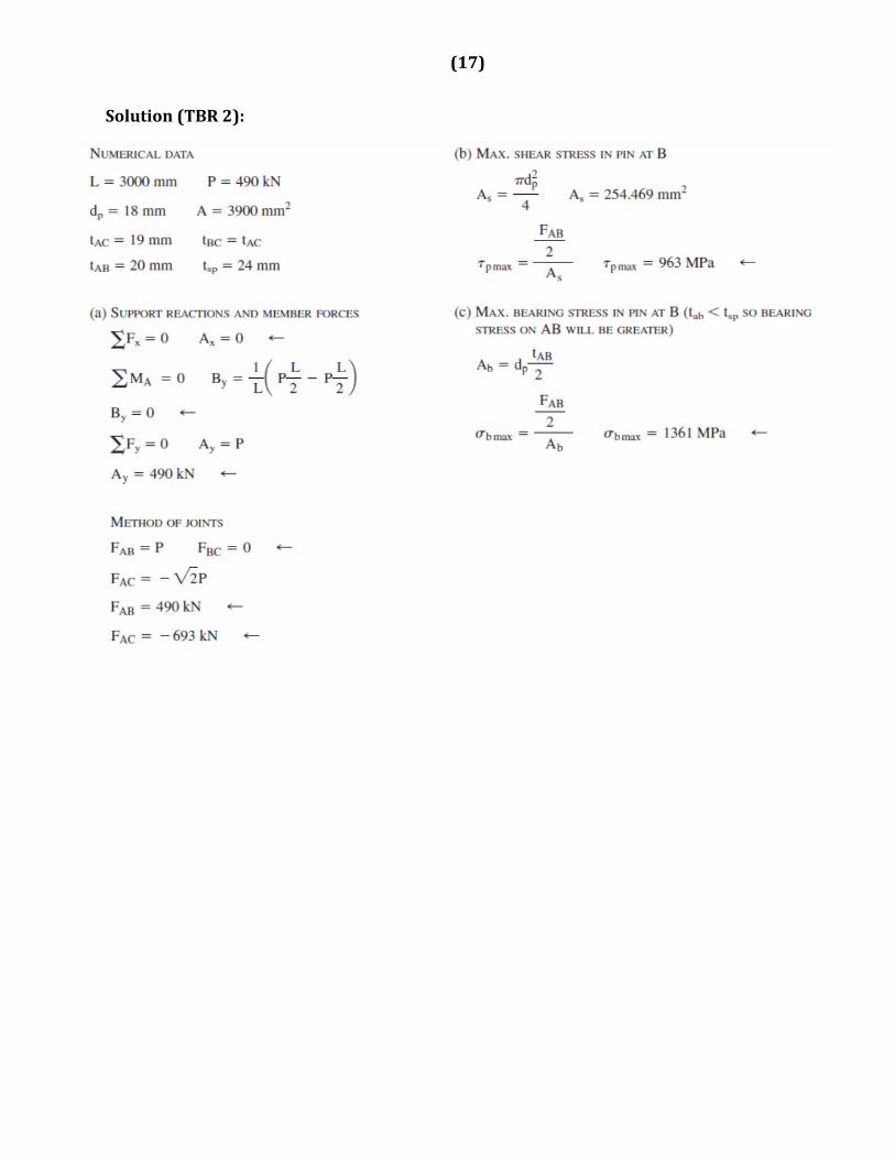
Solution(TBR2):
(18)
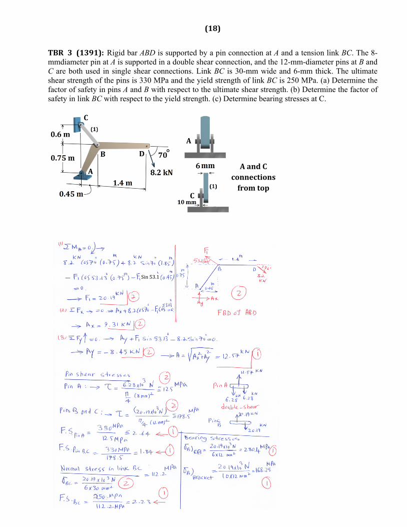
TBR 3 (1391): Rigid bar ABD is supported by a pin connection at A and a tension link BC. The 8-mmdiameter pin at A is supported in a double shear connection, and the 12-mm-diameter pins at B and C are both used in single shear connections. Link BC is 30-mm wide and 6-mm thick. The ultimate shear strength of the pins is 330 MPa and the yield strength of link BC is 250 MPa. (a) Determine the factor of safety in pins A and B with respect to the ultimate shear strength. (b) Determine the factor of safety in link BC with respect to the yield strength. (c) Determine bearing stresses at C.
AandCconnectionsfromtop
Sin53.1
(19)
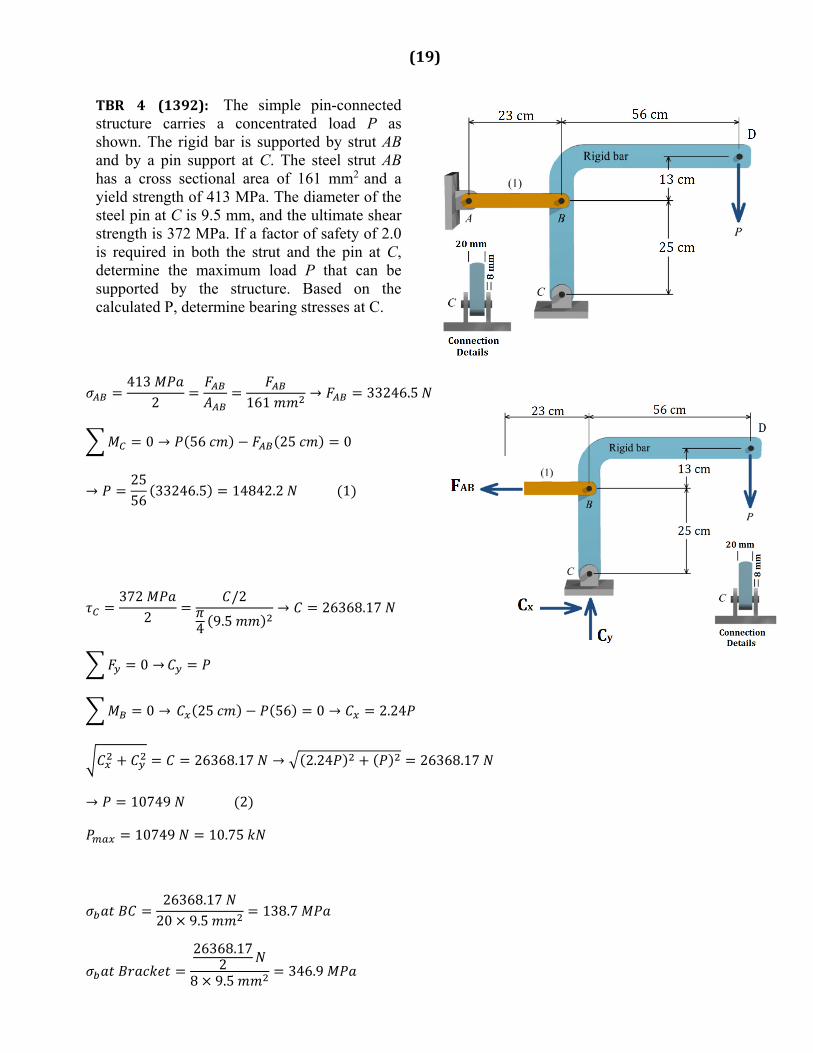
TBR 4 (1392): The simple pin-connected structure carries a concentrated load P as shown. The rigid bar is supported by strut AB and by a pin support at C. The steel strut AB has a cross sectional area of 161 mm2
and a yield strength of 413 MPa. The diameter of the steel pin at C is 9.5 mm, and the ultimate shear strength is 372 MPa. If a factor of safety of 2.0 is required in both the strut and the pin at C, determine the maximum load P that can be supported by the structure. Based on the calculated P, determine bearing stresses at C.
4132 161
→ 33246.5
0 → 56 25 0
→2556
33246.5 14842.2 1
3722
/2
4 9.5→ 26368.17
0 →
0 → 25 56 0 → 2.24
26368.17 → 2.24 26368.17
→ 10749 2
10749 10.75
26368.1720 9.5
138.7
26368.172
8 9.5346.9
(20)
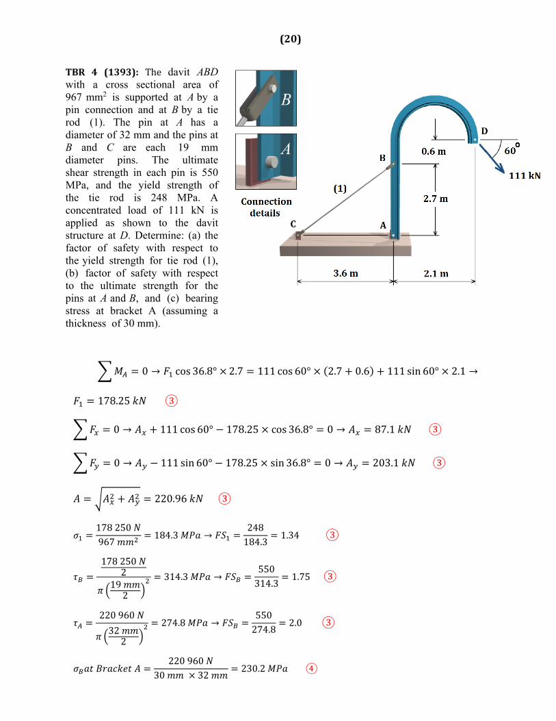
TBR 4 (1393): The davit ABD with a cross sectional area of 967 mm2 is supported at A by a pin connection and at B by a tie rod (1). The pin at A has a diameter of 32 mm and the pins at B and C are each 19 mm diameter pins. The ultimate shear strength in each pin is 550 MPa, and the yield strength of the tie rod is 248 MPa. A concentrated load of 111 kN is applied as shown to the davit structure at D. Determine: (a) the factor of safety with respect to the yield strength for tie rod (1), (b) factor of safety with respect to the ultimate strength for the pins at A and B, and (c) bearing stress at bracket A (assuming a thickness of 30 mm).
0 → cos 36.8° 2.7 111 cos 60° 2.7 0.6 111 sin 60° 2.1 →
178.25 ③
0 → 111 cos 60° 178.25 cos 36.8° 0 → 87.1 ③
0 → 111 sin 60° 178.25 sin 36.8° 0 → 203.1 ③
220.96 ③
178250967
184.3 →248184.3
1.34 ③
1782502
192
314.3 →550314.3
1.75③
220960
322
274.8 →550274.8
2.0 ③
220960
30 32230.2 ④