Embed Size (px)
Citation preview

SCADA
BASED POWER CONTROL SYSTEM
USING PLC
TABLE OF CONTENTS
1. INTRODUCTION
1.1 Introduction
1.2 Why SCADA
1.3 Challenges and Applications
1.4 Research Issues
1.4.1 Flexible Communication Architecture
1.4.2 Open And Interoperable Protocols
1.4.3 Smart remote terminal units
1.5 Potential Benefits Of SCADA
1.6 Cyber Security for SCADA
1.6.1 SCADA Security
1.6.2 Commodity Infrastructure
1.6.3 Network Architecture
1.6.4 Confidentiality
1.6.5 Authentication
1

1.6.6 Lack of Session Structure
2. SYSTEM DEVELOPMENT
2.1 Block Diagram
2.2 Main components of project
2.2.1 Switch Mode Power Supply
2.2.2 Power Relays
2.2.2.1 Physical Size And Pin Arrangement
2.2.2.2 Coil Voltage
2.2.2.3 Coil Resistance
2.2.2.4 Switch Ratings (Voltage and Current)
2.2.2.5 Switch Contact Arrangement (SPDT, DPDT etc)
2.2.3 Serial Interface (RS232)
2.2.3.1 RS232 Serial Cable Layout
2.2.3.2 RS232 Serial Connector Pin Assignment
2

3 PROGRAMABLE LOGIC CONTROLLER (PLC)
3.1 Hardware Overview
3.2 PLC‘s Input And Outputs Terminals
3.3 Horizontal View of PLC
3.4 Vertical View of PLC
3.5 Wiring Diagram of PLC
3.6 Connection of computer with PLC
3.7 Principles of Machine Control
3.8 DH-485 Network
3.9 Principles of Machine Control
3.9 Memory Features of Micrologix 1000 PLC
3.10 Processing Features of Micrologix 1000 PLC
3.11 Operating Cycle of PLC
3.12 Software Features of Micrologix 1000 PLC
3.13 System Requirements for Micrologix 1000 PLC
3.14 Power Distribution
3.15 Preventing Excessive Heat
4. SOFTWARE IMPLEMENTATION
5. CONCLUSION
3

CHAPTER 1 INTRODUCTION
1.1 INTRODUCTION
Using powerful technologies, based on experience of
qualified personal, SCADA (Supervisory Control And Data
Acquisition) applications are created as a main tool for performing
management, required by technical reengineering of an industrial
company. In modern manufacturing and industrial processes,
mining industries, public and private utilities, leisure and security
4

industries, control systems are often needed to connect equipment
and systems separated by large distances. These systems are used
to send commands, programs and receives monitoring information
from these remote locations. SCADA refers to the combination of
control systems and data acquisition. In the early days of data
acquisition, relay logic was used to control production and plant
systems. With the advent of the CPU (Central Process Unit) and
other intelligent electronic devices, manufacturers incorporated
digital electronics into relay logic equipment. The PLC
(Programmable Logic Controller) is still one of the most widely
used control systems in industry.
1.2 WHY SCADA ?
SCADA provides several unique features that make it a
particularly good choice
for many control problems. The features are as follows:
the computer control primary equipments, record an store a
very large amount of data from process
the operator can incorporate real data simulations into the
system
the operator is assist by computer that recommend actions to
keep the system safety
5

many types of data can be collected from the RTUs (Remote
Terminal Unit), this creates online the image of the system.
1.3 CHALLENGES AND APPLICATIONS
Supervisory Control And Data Acquisition (SCADA)
systems have been widely used in industry applications. Due to
their application specific nature, most SCADA systems are heavily
tailored to their specific applications. For example, a remote
terminal unit (RTU) that monitors and controls a production well
in an oilfield is only connected with a few sensors at the well it
resides. The RTU usually collects sensor data at pre-defined
intervals , and only sends data back when being polled by a central
data server. A user can only access the data in one of the two ways:
directly connecting to the RTU in the field or reading from the data
server in the control room. A major drawback of typical SCADA
systems is their inflexible, static, and often centralized architecture,
which largely limits their interoperability with other systems. For
example, in a SCADA system developed for oil and gas fields, the
RTUs are usually places at production wells and injection wells.
However, there are many other places, such as pipeline, tanks, etc.,
that have valuable data but are too expensive (e.g., cable
6

requirement) to deploy more RTUs. In such cases, sensor networks
are a perfect solution to extend the sensing capability of the
SCADA system. However, it is difficult to integrate sensor
networks with current SCADA systems due to their limited
interoperability. We identify that enabling such interoperability is
an important task for future SCADA systems.
Another drawback of the current SCADA systems is their
limited extensibility to new applications. In the above oilfield
monitoring example, a user in the field can only access a sensor’s
data by physically going to that well and connecting to its RTU. If
the company wants to extend its SCADA system by adding a safety alarm system, it will be very difficult to add
the new application.
The original application only monitors well production at
predefined intervals or on demand. The new application requires
7

real-time interaction between sensors and mobile users in the field.
The RTUs that detect a safety problem need to proactively report
the problem without waiting. The rigid design of current RTUs
makes it hard to extend the SCADA from one application to
another.
Deploying a SCADA system in a large field is very
expensive If the SCADA system is interoperable with new
technologies, such as sensor networks, and extensible for new
applications, it will be able to significantly improve the
productivity at a minimal cost.
1.4 RESEARCH ISSUES
This section identifies major research issues to enable
interoperability and extensibility of future SCADA systems. We
roughly classify them in three categories:
Flexible communication architecture,
Open and interoperable protocols, and
Smart remote terminal units.
1.4.1 Flexible Communication Architecture
Current SCADA systems are essentially a centralized
communication system, where the data server polls each remote
8

terminal unit (RTU) to collect data. There is no data sharing and
forwarding between different RTUs. Usually these RTUs only
communicate with the data server. This communication
architecture is not flexible to interact with other systems, such as
the embedded sensor networks and mobile users in the field.
Designing a flexible communication architecture is one of the key
factors to enable interoperability and extensibility.
1.4.2 Open And Interoperable Protocols
We suggest that SCADA systems should adopt the use
of Internet technologies for networking, rather than proprietary or
link-level approaches. collect and manipulate different types of
sensor data. It also includes how to discover and configure sensors.
An open protocol should be extensible to support various types of
sensors. These protocols should also address what types of data
should be transmitted and to whom. For example, raw data are
only sent to data server for archival. Status summaries will be sent
to managers and engineers, while emergency safety alarms should
be broadcast to all field operators.
9

1.4.4 Smart remote terminal units
Remote terminal units play an important role in the new
communication architecture we described above. They serve as
bridge points to sensor networks as well as access points to mobile
users in the field. They respond to users queries and collect data
from specific sensors. These RTUs should be smart enough to
perform preliminary data processing. The first reason is to validate
the data collected from different sensors. Sensors can give false
values due to various reasons. It is important to validate them
before use them to make important decisions. For example, in
oilfield monitoring, a false sensor reading may result in a mistaken
decision to shut in a well and lose production. The RTU is in a
good position to validate sensor readings by cross checking from
adjacent sensors.
Another reason of requiring smart RTUs is that they are
important in changing the reactive operation to proactive
operation. Current SCADA systems mainly operate in the reactive
mode, where data are usually sent in response to the data server’s
polling.
10

In a new class of applications, detection needs to be done in
real time, and events need to be reported immediately, such as
pipeline leakage, or H2S detection. Intelligent algorithms will run
on these smart RTUs to process data in real time.
Finally, these RTUs need to be smart enough to protect data
from unauthorized access and altering. Access control and security
measures need to be installed to protect the sensing system from
attackers and ensure data integrity.
1.5 POTENTIAL BENEFITS OF SCADA
The benefits one can expect from adopting a SCADA system
for the control of experimental physics facilities can be
summarized as follows:
• a rich functionality and extensive development facilities. The
amount of effort invested in SCADA product amounts to 50 to
100 p-years!
• the amount of specific development that needs to be performed
by the end-user is limited, especially with suitable engineering.
• reliability and robustness. These systems are used for mission
critical industrial processes where reliability and performance
are paramount. In addition, specific development is performed
11

within a well-established framework that enhances reliability
and robustness.
• technical support and maintenance by the vendor.
For large collaborations, as using a SCADA system for their
controls ensures a common framework not only for the
development of the specific applications but also for operating the
detectors. Operators experience the same" look and feel" whatever
part of the experiment they control. However, this aspect also
depends to a significant extent on proper engineering.
1.6 CYBER SECURITY FOR SCADA
Cyber security for SCADA Systems provides a high-level
overview of this unique technology, with an explanation of each
market segment. Cyber security for SCADA Systems is suitable
for the non-technical management level personnel as well as IT
12

personnel without SCADA experience. The security issues with
SCADA systems as follows :
Traditionally SCADA systems were designed around
reliability and safety. Security was not a consideration. However,
security of these systems is increasingly becoming an issue due to:
increasing reliance on public telecommunications networks
to link previously separate SCADA systems is making them
more accessible to electronic attacks;
increasing use of published open standards and protocols, in
particular Internet technologies, expose SCADA systems to
Internet vulnerabilities;
the interconnection of SCADA systems to corporate
networks may make them accessible to undesirable entities;
lack of mechanisms in many SCADA systems to provide
confidentiality of communications means that intercepted
communications may be easily read;
lack of authentication in many SCADA systems may result in
a system user’s identity not being accurately confirmed.
1.6.1 SCADA Security
The majority of SCADA systems have useful lifetimes
ranging from 15 to 30 years. In most instances the underlying
protocols were designed without modern security
13

requirements in mind. The rapid advance of technology and the
changing business environment is driving change in SCADA
network architecture, introducing new vulnerabilities to legacy
systems.
The current push towards greater efficiency, consolidated
production platforms and larger companies with smaller staffing
levels is leading to changes in SCADA systems which are raising
many questions about security.
In summary, these involve:
an increasing reliance on public telecommunications
networks to link previously separate SCADA systems;
increasing use of published open standards and protocols, in
particular Internet technologies; and
the interconnection of SCADA systems to other business
networks to enhance the amount, detail and timeliness of
information available to management.
1.6.2 Commodity Infrastructure
The changes in SCADA systems have exposed them to
vulnerabilities that may not have existed before. For example, the
14

switch from using leased telecommunications lines to public
infrastructure i.e. Public CDMA and GSM networks, the use of
commodity computers running commodity software and the
change from proprietary to open standards have meant that
vulnerabilities have been introduced into SCADA systems.
1.6.3 Network Architecture
Effective network design which provides the appropriate
amount of segmentation between the Internet, the company’s
corporate network, and the SCADA network is critical to risk
management in modern SCADA systems. Network architecture
weakness can increase the risk from Internet and other sources of
intrusion.
1.6.4 Confidentiality
Generally, there are no mechanisms in SCADA to provide
confidentiality of communications. If lower level protocols do not
provide this confidentiality then SCADA transactions are
communicated “in the clear” meaning that intercepted
communications may be easily read.
15

1.6.5 Authentication
Many SCADA systems give little regard to security, often
lacking the memory and bandwidth for sophisticated password or
authentication systems. As a result there is no mechanism to
determine a system user’s identity or what that user is authorized
to access. This allows for the injection of false requests or replies
into the SCADA system.
1.6.6 Lack of session structure
SCADA systems often lack a session structure which, when
combined with the lack of authentication, allow the injection of
erroneous or rogue requests or replies into the system without any
prior knowledge of what has gone on before.
16

CHAPTER 2
SYSTEM DEVOLPMENT
2.1 BLOCK DIAGRAM
The block diagram of the SCADA based power control system is shown:
17

Figure 2.1 Block Diagram Of the SCADA and PLC based control system
2.2 Main components of project are as follow:
1. SMPS (+24 VDC)
18

2. RELAYS ( 24 VDC, 50/60Hz)24 VDC, 50/60Hz)
3. Serial Interface (RS-232)
4. PLC (6/4)
5. COMPUTER
2.2.1 SWITCH MODE POWER SUPPLY (SMPS)
The picture of SMPS used is shown below and their features
are as follows:
High efficiency, high reliability,
AC input range selected by switch
100% full load burn-in test.
Protections: Short circuit/ Over load/
Over voltage Fixed switching frequency
at 25KHz.
Dimensions: 199*110*50mm
L*W*H
Figure 2.2.1 Physical
Structure Of SMPS
Point to note for selecting a SMPS.
19
SMPS (+24VDC)SMPS (+24VDC)Inputs 115 AC (2.4A) , 230AC (4.5A)Inputs 115 AC (2.4A) , 230AC (4.5A)Outputs +24V (4.5A)Outputs +24V (4.5A)

1. All parameters NOT specially mentioned are measured at
230VAC input, rated load and 25*C of ambient temperature.
2. Ripple & noise are measured at 20MHz of bandwidth by using a
12″twisted pair-wire terminated with a 0.1μ & 47μ parallel
capacitor.
3. Each output can within current range. But total output power
can’t exceed rated load.
4. The power supply is considered a component which will be
installed into a final equipment. The final equipment must be re-
confirmed that it still meets EMC directives.
2.2.2 POWER RELAYS
The coil of a relay passes a relatively large current, typically
7a for a 24V relay, but it can be as much as 100mA for relays
designed to operate from lower voltages. Most ICs (chips) cannot
provide this current and a transistor is usually used to amplify the
small IC current to the larger value required for the relay coil.
Relays are usually SPDT or DPDT but they can have many
more sets of switch contacts, for example relays with 4 sets of
20

changeover contacts are readily available. For further information
about switch contacts and the terms used to describe them. We are
using three relays in our project . The picture of the relay used is
shown below:
Figure 2.2.2 Physical Structure Of Power Relay
The need to consider several features when choosing a relay:
2.2.2.1 Physical Size And Pin Arrangement
21

If you are choosing a relay for an existing PCB you will
need to ensure that its dimensions and pin arrangement are suitable.
You should find this information in the supplier's catalogue.
2.2.2.2 Coil Voltage
The relay's coil voltage rating and resistance must suit the
circuit powering the relay coil. Many relays have a coil rated for a
12V supply but 5V and 24V relays are also readily available. Some
relays operate perfectly well with a supply voltage which is a little
lower than their rated value.
2.2.2.3 Coil Resistance
The circuit must be able to supply the current required by the
relay coil. You can use Ohm's law to calculate the current:
Voltage/Resistance
22

2.2.2.4 Switch Ratings (Voltage and Current)
The relay's switch contacts must be suitable for the circuit
they are to control. You will need to check the voltage and current
ratings. Note that the voltage rating is usually higher for AC, for
example: "5A at 24V DC or 125V AC".
2.2.2.5 Switch Contact Arrangement (SPDT, DPDT etc)
Most relays are SPDT or DPDT which are often described as
"single pole changeover" (SPCO) or "double pole changeover"
(DPCO).
Advantages to use of Relays:
Relays can switch AC and DC, transistors can only switch
DC.
Relays can switch high voltages, transistors cannot.
Relays are a better choice for switching large currents (> 5A).
Relays can switch many contacts at once.
23

2.2.3 SERIAL INTERFACE (RS232)
2.2.3.1 RS232 Serial Cable Layout
Almost nothing in computer interfacing is more confusing
than selecting the right RS232 serial cable. These pages are
intended to provide information about the most common serial
RS232 cables in normal computer use, or in more common
language "How do I connect devices and computers using RS232".
2.2.3.2 RS232 Serial Connector Pin Assignment.
The RS232 connector was originally developed to use 25
pins. In this DB25 connector pin out provisions were made for a
secondary serial RS232 communication channel.
In practice, only one serial communication channel with
accompanying handshaking is present. Only very few computers
have been manufactured where both serial RS232 channels are
implemented. Examples of this are the Sun Sparc Station 10 and 20
models and the Dec Alpha Multia. Also on a number of Telebit
modem models the secondary channel is present. It can be used to
24

query the modem status while the modem is on-line and busy
communicating. On personal computers, the smaller DB9 version
is more commonly used today. The diagrams show the signals
common to both connector types in black. The defined pins only
present on the larger connector are shown in red. Note, that the
protective ground is assigned to a pin at the large connector where
the connector outside is used for that purpose with the DB9
connector version.
The pin out is also shown for the DEC modified modular
jack. This type of connector has been used on systems built by
Digital Equipment Corporation; in the early days one of the leaders
in the mainframe world. Although this serial interface is
differential (the receive and transmit have their own floating
ground level which is not the case with regular RS232) it is
possible to connect RS232 compatible devices with this interface
because the voltage levels of the bit streams are in the same range
25

Figure 2.2.3 (a) RS232 Serial Connector Pin
Assignment.
The picture of the serial interface used is shown below:
26
RS 232Serial Interface (Female Part)
RS 232 Serial Interface (Male Part)

Figure 2.2.3(b) Physical Structure Of Serial Interface RS 232
(Female and Male Part)
Figure 2.2.3(c) Connection Diagram Of Serial Interface RS
232(Female and Male Part)
CHAPTER 3
PROGRAMABLE LOGIC CONTROLLER (PLC)
3. MICROLOGIX 1000 PROGRAMMABLE
CONTROLLERS
The MicroLogix 1000 Programmable Controllers are
designed to electronically control your application. The controllers
27

are available in either 16 I/O points (10 inputs and 6 outputs) or 32
I/O points (20 inputs and 12 outputs) in 5 electrical configurations.
The I/O options and electrical configurations make them ideal for
almost any application.
The controllers are programmed in familiar ladder logic. This
symbolic programming language is based on relay ladder wiring
diagrams that simplify the creation and troubleshooting of your
control program. The comprehensive instruction set includes
simple bit, timer, and counter instructions as well as powerful
application instructions such as sequencers, high-speed counter,
and shift registers.
To get your application running smoothly, you need a quick
and simple way to program your controller. The MicroLogix 1000
Programmable Controller family offers you two software packages
and one diagnostic hand-held programmer to help you accomplish
this task.
The MicroView Operator Interface enables you to monitor
and control your application with a combination of large memory
capacity, flexible file addressing, user-defined function keys, and
an easy-to-read display. Contact your local Allen-Bradley
distributor for more information concerning the MicroView
Operator Interface and accessories
28

3.1 Hardware Overview
The MicroLogix 1000 programmable controller is a packaged
controller containing a power supply, input circuits, output circuits,
and a processor. The controller is available in 10 I/O, 16 I/O and
32 I/O configurations, as well as an analog version with 20 discrete
I/O and 5 analog I/O. We are using 10 I/O Configuration:
In such PLC, Inputs are six and outputs are four. The picture
of the PLC used is shown below:
29

Figure 3.1 Physical Structure Of PLC (Micrologix 1000)
3.2 PLC‘s Input And Outputs Terminals
Two I/O point sizes (i.e., 16 and 32 I/O). Covers a breadth of
applications.
Five electrical configurations. Offers you a controller that meets
your electrical requirements:
1. 24V dc inputs and relay outputs with a 120/240V ac power
supply.
2. 120V ac inputs and relay outputs with a 120/240V ac power
supply.
3. 24V dc inputs and relay outputs with a 24V dc power supply.
4. 24V dc inputs and 24V dc FET and relay outputs with a 24V
dc power Supply.
5. 120V ac inputs and triac and relay outputs with a 120/240V ac
power supply.
30

Five output commons on relay output units and three on
MOSFET units (at least two isolated relays per controller). Allows
outputs on the same unit to switch different control voltages.
Multiple input commons. Allows the controller with DC
inputs to accept sink and source type sensors.
Compact size. Enables the MicroLogix 1000 Programmable
Controller to fit in tight spaces.
Adjustable DC input filters. Allows you to customize your
input response time to various applications. For a listing of
the adjustable DC input filter settings.
Built-in sensor DC power supply on AC powered units.
Eliminates the need for an external DC power supply in
many applications.
RS-232 communication channel. Allows you to connect the
controller directly to your personal computer or telephone
modem.
Auto-ranging AC power supply. Allows you to install the
MicroLogix 1000 Programmable Controller in virtually any
application worldwide.
OEM protection. Allows you to protect proprietary
algorithms, prevent program alterations, and stop
unauthorized access to the controller.
31

32

The hardware feature of the controller are:
Figure 3.2 Hardware Structure Of PLC
33

3.3 Horizontal View Of PLC
Figure 3.3 Horizontal View Of PLC
3.4 Vertical View Of PLC
34
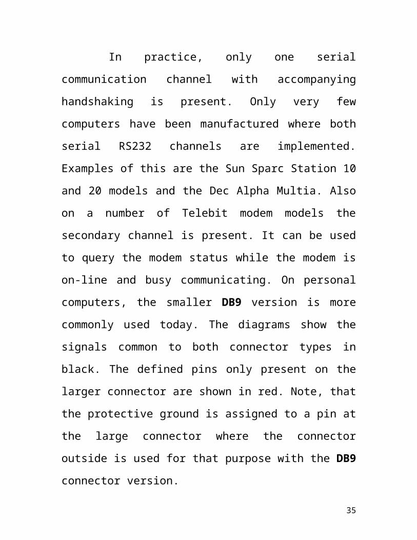
Figure 3.4 Vertical View of PLC
3.5 Wiring Diagram Of PLC
The connection with wires as shown in the wiring of PLC
35

Figure 3.5 Wiring Diagram Of PLC
3.6 Connection of Computer With PLC
36

The connection of Micrologix 1000 PLC with PC as point to
point connection is shown below:
Figure 3.6 Point to Point Connection Of PC To PLC
37

3.7 DH-485 Network
38

3.8 Principles Of Machine Control
The controller consists of a built-in power supply, central
processing unit (CPU),inputs, which you wire to input devices
(such as pushbuttons, proximity sensors, limit switches), and
outputs, which you wire to output devices (such as motor starters,
solid-state relays, and indicator lights).
39

With the logic program entered into the controller, placing
the controller in the Run mode initiates an operating cycle. The
controller’s operating cycle consists of a series of operations
performed sequentially and repeatedly, unless altered by your
program logic.
3.9 Memory Features Of Micrologix 1000 PLCBuilt-in EEPROM memory. Retains your program and all of
your data if your controller loses power, eliminating the need for
40

battery or capacitor backup. Optimized 1K user memory capacity.
Provides ample memory to meet your application needs including:
over 735 word application program.
more than 250 data words comprised of 512 bits, 40 timers,
32 counters, 16 controls, 105 integers, and 33 diagnostic
registers comprehensive instruction set.
Allows you to develop a program using over 65 programming
instructions from the following categories:
– bit
– timer/counter
– comparison
– math
– data handling
– program flow
– application specific (e.g., sequencer, shift register, and
FIFO/LIFO)
– high-speed counter
Efficient instructions. Condenses multiple rungs into a single
instruction.
3.9 Processing Features of Micrologix 1000 PLC
41

Superior high-speed counter. Offers immediate control of
program outputs since the high-speed counter operates independent
of the program scan. In addition, the high-speed counter provides:
high count frequency of 6.6 kHz
eight operating modes including up count, bi-directional, and
quadrate
interrupt latency of less than 1ms.
Fast throughput. Allows for typical throughput time of 1.5 ms
for a 500 instruction program._ Throughput is the time it takes for
the controller to sense an input to the time of controlling a
corresponding output. To calculate your program execution time.
The On/Off status in the output image table is sent to the outputs to
turn physical devices On and Off.
The status of contacts in the program is determined from the
I/O tables.
Instructions are executed.
New status of output coils and registers are written to the
output image table.
42

The On/Off status of the input devices are read from the
inputs and written into the input image table. Communication with
development tools; internal housekeeping, such as updating the
time base and status file, and performing rescan
3.10 Operating Cycle Of PLC
Input scan – the time required for the controller to scan and
read all input data typically accomplished within seconds.
Program scan – the time required for the processor to
execute the instructions in the program. The program scan
time varies depending on the instructions used and each
instruction’s status during the scan time.
Output scan – the time required for the controller to scan
and write all output data typically accomplished with in
seconds.
Service communications – the part of the operating cycle in
which communication takes place with other devices, such as
an HHP or personal computer.
Housekeeping and overhead – time spent on memory
management and updating timers and internal registers. You
enter a logic program into the controller using a
43

programming device. The logic program is based on your
electrical relay.
Figure 3.8 Operating Cycle Of PLC
Program Development Process For PLC as follows :
How you want your automated process to operate ?
Identify the hardware requirements.
Match inputs and outputs with actions of the process.
Add these actions to the functional specifications.
44

Do you need:
Special interrupt routines?
High-speed counting features?
Sequencing Operations?
FIFO or LIFO stack operations?
Make sure I/O addresses match correct input and output
devices.
Enter program using the programming device.
Review your functional specification and detailed analysis
for missing or incomplete information.
Monitor and, if necessary, troubleshoot the program that you
entered.
Resulting programs should match functional specifications.
3.12 Software Features of Micrologix 1000
Both the MicroLogix 1000 Programming Software (v1.0 or
later) and APS software (v5.1 or later) offer:
Program documentation. Allows you to add comments to
rungs, instructions,
45

and addresses.
Online context sensitive help. Makes programming and
troubleshooting easier to perform.
Cut, copy, and paste editor. Allows you to efficiently
modify your ladder logic program.
Search and replace. Allows quick modification of ladder
logic to accommodate program changes.
RS-232 DF1 full duplex protocol. Supports remote
programming through a telephone modem.
Program reports. Allows you to create processor
configuration, cross reference, program listing, and data
table reports.
Global language support. Provides separate programming
packages In English, French, German, Italian, and
Spanish.
Command line entry of instructions and parameters. Saves
time by reducing keystrokes.
3.13 System Requirements for Micrologix 1000
46

Both the MicroLogix 1000 Programming Software (v1.0 or
later) and APS ( v5.1 or later) can be used with:
Allen-Bradley T47 or T70 terminal
386/SX
NEC VERSAE Series Notebook
GATEWAY 2000models 386DX/25, 386DX33,
486DX/33, 486DX2/50, and 486DX2/66 personal computers
The computer must have:
640 Kbytes of RAM (At least 2 meg. of extended memory is
required.)
10 M byte fixed-disk drive (APS requires 3.5 Mbytes of free
disk space.)
DOS version 3.3 or higher
3.14 Power Distribution
There are some points about power distribution that you
should know:
The master control relay must be able to inhibit all machine
motion by removing power to the machine I/O devices when
the relay is de-energized.
If you are using a dc power supply, interrupt the load side
rather than the ac line power. This avoids the additional delay
of power supply turn-off. The dc power supply should be
47

powered directly from the fused secondary of the
transformer. Power to the dc input and output circuits is
connected through a set of master control relay contacts.
3.15 Preventing Excessive Heat
For most applications, normal convective cooling keeps the
controller within. The specified operating range. Ensure that the
specified operating range is maintained. Proper spacing of
components within an enclosure is usually sufficient for heat
dissipation.
CHAPTER 5
Conclusion
The trend in automated power systems is to use SCADA
systems based on PLCs, advanced communication systems, and
PC-based software. This project presents the basic knowledge
needed to choose technology, design a system, and select a
SCADA system. For power control SCADAs mostly used as
designing, integrating, installing, and maintaining automated
power systems as follows :
48

Control system architecture, design, and specification
generation
CAD-based layout and design of control enclosures and
RTUs
Fabrication of control panels in a UL-certified shops.
SCADA software programming from leading vendors like
ROCKWELL.
Integration of industrially-hardened PLC-based control
systems.
Field start-up, calibration, and training services.
Support and maintenance services for existing systems
49

OTHER APPLICATIONS
1. WATER/CO2 INJECTION WELL SCADA MONITORING
SYSTEM
2. PUMPJACK/SCREWPUMP SCADA & TELEMETRY.
3. WATER DISPOSAL HIGH TANK LEVEL SHUTDOWN
SYSTEM
4. VARIABLE FREQUENCY DRIVE (VFD) SCADA
COMMUNICATION
5. SEWAGE TREATMENT PLANT INFLOW TELEMETRY
6. MUNICIPAL WATER SYSTEM - TAIL END DATA
EXTENSION & WIDE
AREA SCADA.
7. REMOTE VALVE CONTROL
8. CELLULAR TELEMETRY
9. WATER RESERVOIR PUMP CONTROL
50
51