Embed Size (px)
DESCRIPTION
10
Citation preview
Unit 14: Structural Mechanics in Construction and Civil Engineering
Chapter 10 Page 1
Chapter 10Load Transfer
10.1 Introduction
Load will be transferred through a structure and to its foundation. Thus
the load imposed from a roof structure must, somehow, be transferred
through other structural elements until it is finally resisted by the earth
supporting the foundations. In order to design the roof members , we will
first need to determine how much load they are to carry. Having designed
the roof, we might then consider the design of the walls supporting the
roof structure and, as such, we must determine how much of the roof
load will be transferred to the wall. We might then consider the floor or
other structural member. Whatever member we decide to design, we
must first determine how much load it will be required to carry. This will
be based on its position in the structure and on how the loads are
transferred from part to part. To demonstrate the problem, consider the
simple structure of Example 10.1, shown in Figure 1.
Example 10.1: Calculation of loads for a simple structure
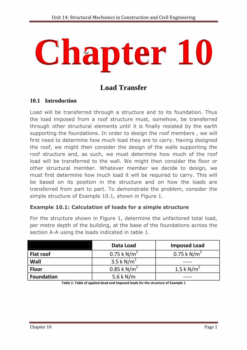
For the structure shown in Figure 1, determine the unfactored total load,
per metre depth of the building, at the base of the foundations across the
section A-A using the loads indicated in table 1.
Data Load Imposed Load
Flat roof 0.75 k N/m2 0.75 k N/m2
Wall 3.5 k N/m2 -----
Floor 0.85 k N/m2 1.5 k N/m2
Foundation 5.6 k N/m ----- Table 1: Table of applied dead and imposed loads for the structure of Example 1
Unit 14: Structural Mechanics in Construction and Civil Engineering
Chapter 10 Page 2
Answer
First it is important to note that we will be calculating the load per metre
depth of the building. Secondly, the dead load induced by the foundation
is given for the structure in Table 1. Often, only the density of the
concrete is known, in which case we will need to calculate the force per
metre from the volume of the foundation. Finally, there is no imposed
load on the wall. This is because, in this case, the imposed loads have
been included in the load-carrying floor and roof elements and, as we are
only calculating vertical imposed loads, the wind effects need not be
considered here. This will simplify the analysis of the structure.
In order to complete the load analysis of the structure, we must
determine how much of each load is transferred to each of the
foundations.
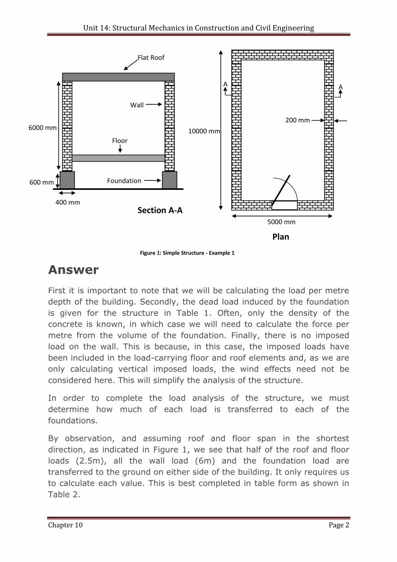
By observation, and assuming roof and floor span in the shortest
direction, as indicated in Figure 1, we see that half of the roof and floor
loads (2.5m), all the wall load (6m) and the foundation load are
transferred to the ground on either side of the building. It only requires us
to calculate each value. This is best completed in table form as shown in
Table 2.
Wall
Flat Roof
Floor
Foundation 600 mm
400 mm
6000 mm 10000 mm
200 mm
5000 mm
A A
Plan
Section A-A
Figure 1: Simple Structure - Example 1
Unit 14: Structural Mechanics in Construction and Civil Engineering
Chapter 10 Page 3
Dead Load (k N/m) Imposed Load (k N/m)
Flat roof 0.75 k N/m2 x (5/2)m = 1.875 0.75 k N/m2 x (5/2)m = 1.875
Wall 3.5 k N/m2 x 6m = 21.0 Floor 0.85 k N/m2 x (4.6/2)m = 1.955 1.5 k N/m2 x (4.6/2) m = 3.45
Foundation = 5.6
TOTAL DEAD
30.43 kN/m
TOTAL IMPOSED 5.325 kN/m
Table 2: Total Loads at base of foundation for the structure of example 1
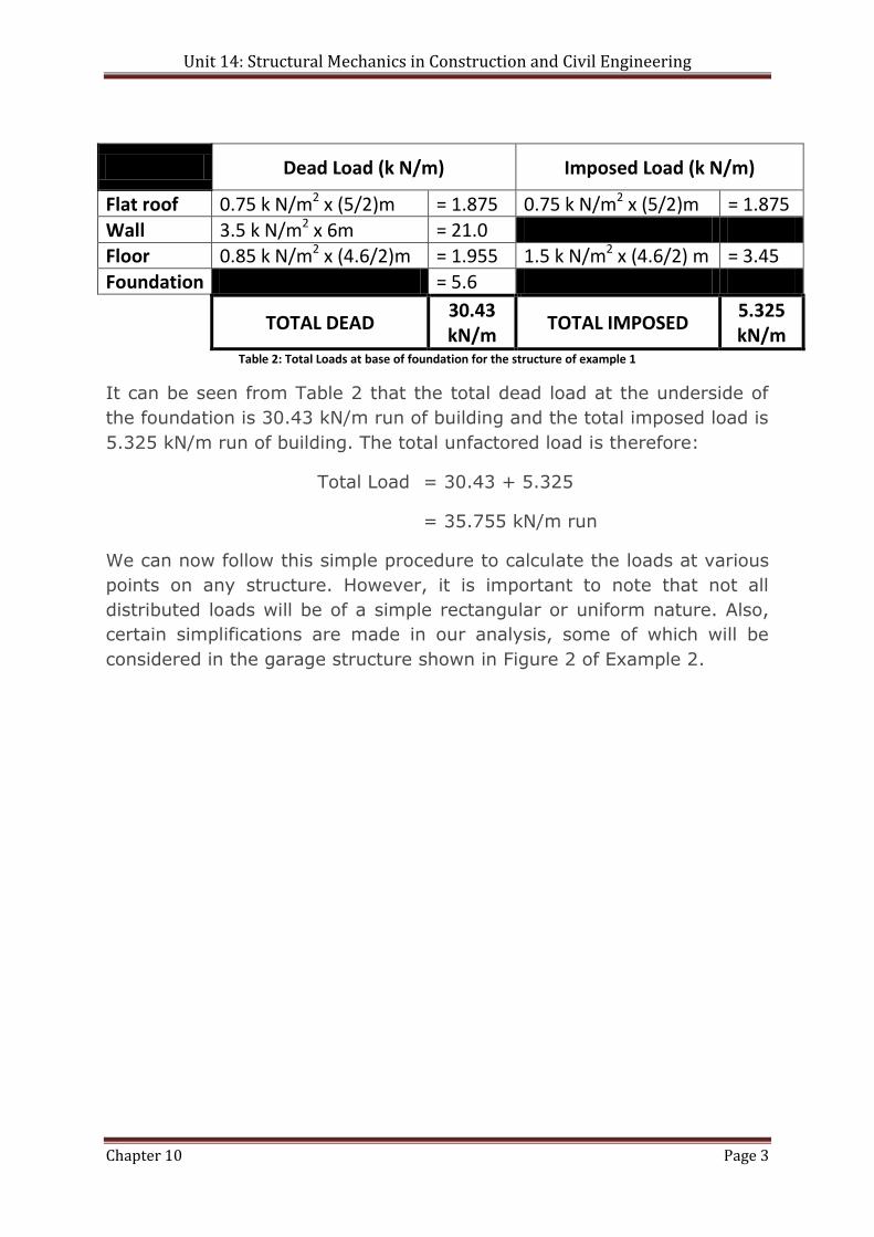
It can be seen from Table 2 that the total dead load at the underside of
the foundation is 30.43 kN/m run of building and the total imposed load is
5.325 kN/m run of building. The total unfactored load is therefore:
Total Load = 30.43 + 5.325
= 35.755 kN/m run
We can now follow this simple procedure to calculate the loads at various
points on any structure. However, it is important to note that not all
distributed loads will be of a simple rectangular or uniform nature. Also,
certain simplifications are made in our analysis, some of which will be
considered in the garage structure shown in Figure 2 of Example 2.
Unit 14: Structural Mechanics in Construction and Civil Engineering
Chapter 10 Page 4
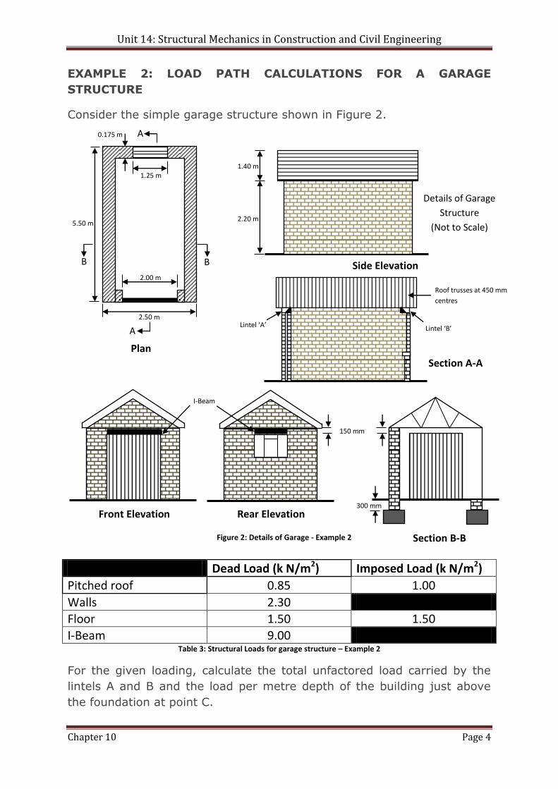
EXAMPLE 2: LOAD PATH CALCULATIONS FOR A GARAGE
STRUCTURE
Consider the simple garage structure shown in Figure 2.
Dead Load (k N/m2) Imposed Load (k N/m2)
Pitched roof 0.85 1.00
Walls 2.30
Floor 1.50 1.50
I-Beam 9.00 Table 3: Structural Loads for garage structure – Example 2
For the given loading, calculate the total unfactored load carried by the
lintels A and B and the load per metre depth of the building just above
the foundation at point C.
Details of Garage
Structure
(Not to Scale)
A
A
B B
5.50 m
1.25 m
0.175 m
2.00 m
2.50 m
Plan
2.20 m
1.40 m
Side Elevation
Lintel ‘A’ Lintel ‘B’
Roof trusses at 450 mm
centres
Section A-A
Figure 2: Details of Garage - Example 2
150 mm
300 mm
Front Elevation Rear Elevation
Section B-B
I-Beam
Unit 14: Structural Mechanics in Construction and Civil Engineering
Chapter 10 Page 5
Answer
Before commencing our analysis of loading for the lintels A and B, let us
consider the pitched roof and its effect on the openings. Although the roof
spans from side to side on the garage and is supported on the walls, in
practice some roof load will be transmitted to the lintels. This is because,
in this case, when constructing the roof, an overhanging section will be
formed. This section can transfer load to the end (or gable) walls. Also
some load will be transmitted because the trusses do not tightly abut the
end walls. In making this allowance some ‘engineering judgement’ must
be used. In this example we will consider the end walls support one span
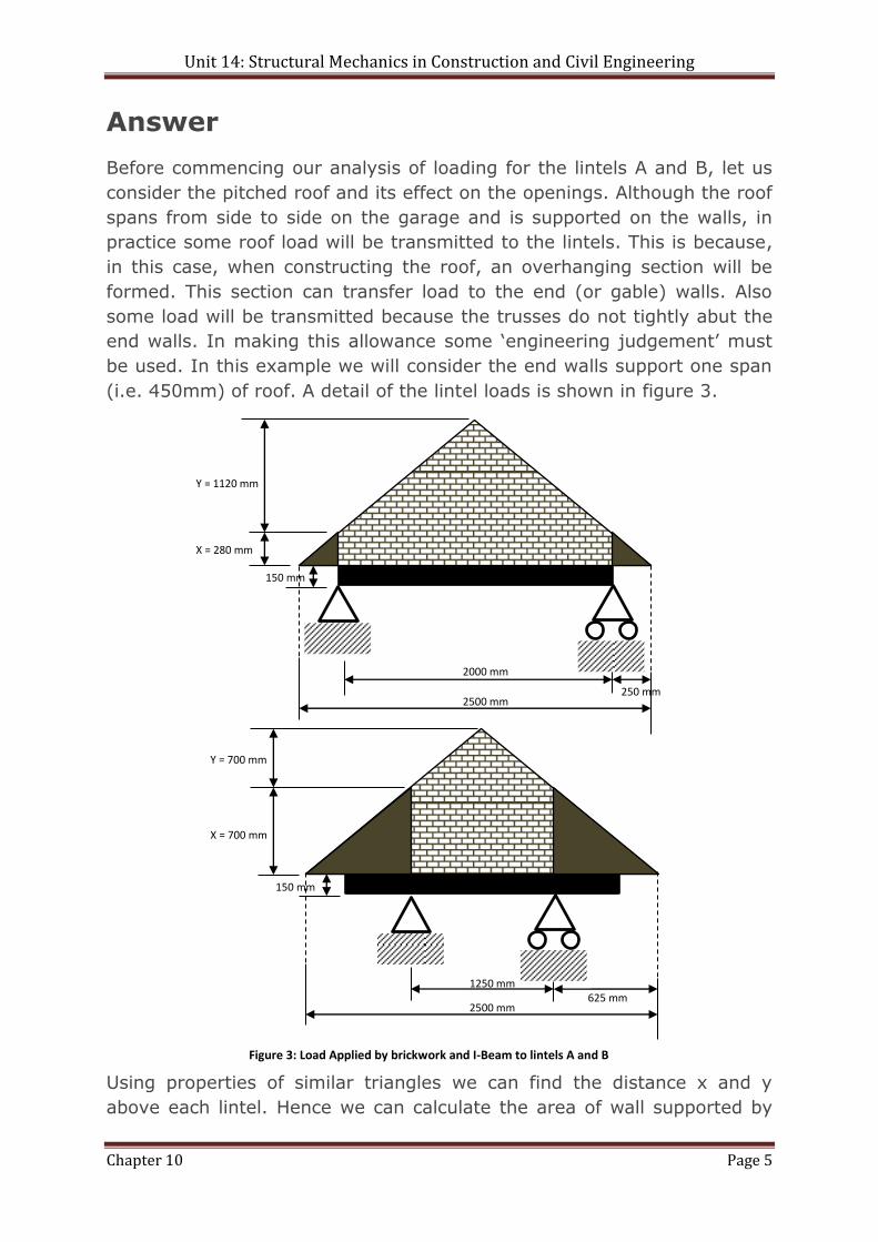
(i.e. 450mm) of roof. A detail of the lintel loads is shown in figure 3.
Using properties of similar triangles we can find the distance x and y
above each lintel. Hence we can calculate the area of wall supported by
150 mm
2000 mm
2500 mm 250 mm
X = 280 mm
Y = 1120 mm
1250 mm
2500 mm 625 mm
150 mm
X = 700 mm
Y = 700 mm
Figure 3: Load Applied by brickwork and I-Beam to lintels A and B
Unit 14: Structural Mechanics in Construction and Civil Engineering
Chapter 10 Page 6
each lintel. To calculate the total load we multiply the area by the value
for dead and imposed load given in Figure 3 plus an allowance for the roof
load hence:
Brickwork Brickwork Pitched Roof I-Beam
Total load on
lintel A =
(0.28m × 2.0m × (2.3 kN/m2))
+
(0.5 × 1.12m × 2.0m × (2.3
kN/m2)) +
(0.45m × 2m × (0.85 + 1.00)
kN/m2) +
(0.15m × 2.0m × (9.0 kN/m2))
= 1.288 + 2.576 + 1.665 + 2.7 = 8.229 kN
Total load on
lintel B =
(0.7m × 1.25m × (2.3 kN/m2))
+
(0.5 × 0.7m × 1.25m × (2.3
kN/m2)) +
(0.45 × 1.25m × (0.85 + 1.00)
kN/m2)
(0.15m × 1.25m × (9.0
kN/m2))
= 2.0125 + 1.00625 + 1.040625 + 1.6875
= 5.75 kN Table 4: Calculation of Load on each Lintel for Example 2
We assume that the lintels support an area equivalent to one truss.
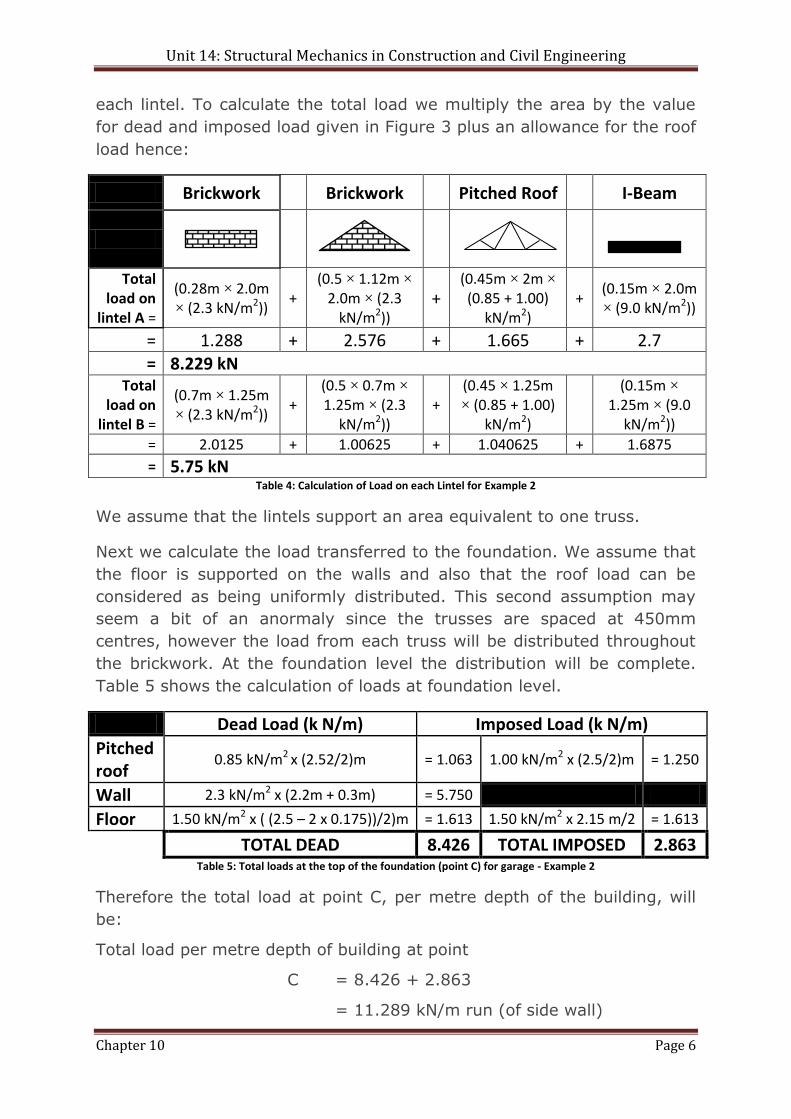
Next we calculate the load transferred to the foundation. We assume that
the floor is supported on the walls and also that the roof load can be
considered as being uniformly distributed. This second assumption may
seem a bit of an anormaly since the trusses are spaced at 450mm
centres, however the load from each truss will be distributed throughout
the brickwork. At the foundation level the distribution will be complete.
Table 5 shows the calculation of loads at foundation level.
Dead Load (k N/m) Imposed Load (k N/m)
Pitched roof
0.85 kN/m2 x (2.52/2)m = 1.063 1.00 kN/m2 x (2.5/2)m = 1.250
Wall 2.3 kN/m2 x (2.2m + 0.3m) = 5.750
Floor 1.50 kN/m2 x ( (2.5 – 2 x 0.175))/2)m = 1.613 1.50 kN/m2 x 2.15 m/2 = 1.613
TOTAL DEAD 8.426 TOTAL IMPOSED 2.863 Table 5: Total loads at the top of the foundation (point C) for garage - Example 2
Therefore the total load at point C, per metre depth of the building, will
be:
Total load per metre depth of building at point
C = 8.426 + 2.863
= 11.289 kN/m run (of side wall)
Unit 14: Structural Mechanics in Construction and Civil Engineering
Chapter 10 Page 7
EXAMPLE 3: LOAD PATH CALCULATIONS FOR A BUILDING
STRUCTURE
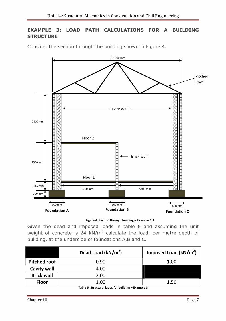
Consider the section through the building shown in Figure 4.
Given the dead and imposed loads in table 6 and assuming the unit
weight of concrete is 24 kN/m3 calculate the load, per metre depth of
buliding, at the underside of foundations A,B and C.
Dead Load (kN/m2) Imposed Load (kN/m2)
Pitched roof 0.90 1.00
Cavity wall 4.00
Brick wall 2.00
Floor 1.00 1.50 Table 6: Structural laods for building – Example 3
600 mm 600 mm 600 mm
5700 mm 5700 mm
300 mm
750 mm
2500 mm
2500 mm
12 000 mm
Pitched
Roof
Cavity Wall
Floor 2
Floor 1
Brick wall
Foundation A Foundation B Foundation C
Figure 4: Section through building – Example 1.4
Unit 14: Structural Mechanics in Construction and Civil Engineering
Chapter 10 Page 8
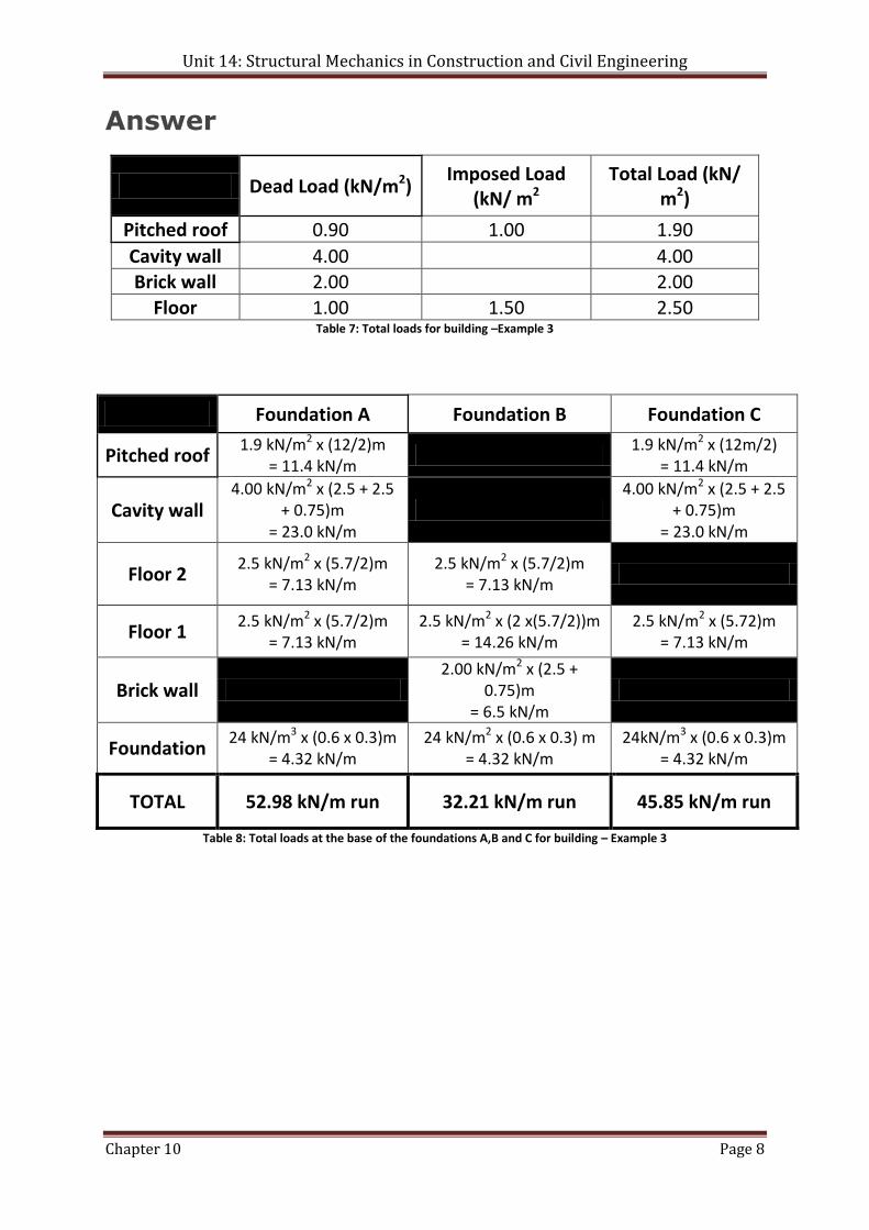
Answer
Dead Load (kN/m2) Imposed Load
(kN/ m2 Total Load (kN/
m2)
Pitched roof 0.90 1.00 1.90
Cavity wall 4.00 4.00 Brick wall 2.00 2.00
Floor 1.00 1.50 2.50 Table 7: Total loads for building –Example 3
Foundation A Foundation B Foundation C
Pitched roof 1.9 kN/m2 x (12/2)m
= 11.4 kN/m
1.9 kN/m2 x (12m/2) = 11.4 kN/m
Cavity wall 4.00 kN/m2 x (2.5 + 2.5
+ 0.75)m = 23.0 kN/m
4.00 kN/m2 x (2.5 + 2.5
+ 0.75)m = 23.0 kN/m
Floor 2 2.5 kN/m2 x (5.7/2)m
= 7.13 kN/m 2.5 kN/m2 x (5.7/2)m
= 7.13 kN/m
Floor 1 2.5 kN/m2 x (5.7/2)m
= 7.13 kN/m 2.5 kN/m2 x (2 x(5.7/2))m
= 14.26 kN/m 2.5 kN/m2 x (5.72)m
= 7.13 kN/m
Brick wall 2.00 kN/m2 x (2.5 +
0.75)m = 6.5 kN/m
Foundation 24 kN/m3 x (0.6 x 0.3)m
= 4.32 kN/m 24 kN/m2 x (0.6 x 0.3) m
= 4.32 kN/m 24kN/m3 x (0.6 x 0.3)m
= 4.32 kN/m
TOTAL 52.98 kN/m run 32.21 kN/m run 45.85 kN/m run
Table 8: Total loads at the base of the foundations A,B and C for building – Example 3
Unit 14: Structural Mechanics in Construction and Civil Engineering
Chapter 10 Page 9
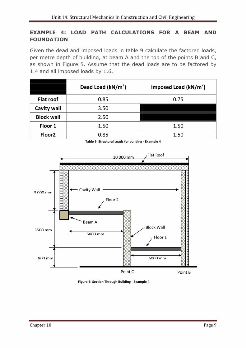
EXAMPLE 4: LOAD PATH CALCULATIONS FOR A BEAM AND
FOUNDATION
Given the dead and imposed loads in table 9 calculate the factored loads,
per metre depth of building, at beam A and the top of the points B and C,
as shown in Figure 5. Assume that the dead loads are to be factored by
1.4 and all imposed loads by 1.6.
Dead Load (kN/m2) Imposed Load (kN/m2)
Flat roof 0.85 0.75
Cavity wall 3.50
Block wall 2.50
Floor 1 1.50 1.50
Floor2 0.85 1.50 Table 9: Structural Loads for building - Example 4
Floor 2
Flat Roof
Block Wall Beam A
Cavity Wall
10 000 mm
3 000 mm
3500 mm
800 mm
5800 mm Floor 1
6000 mm
Figure 5: Section Through Building - Example 4
Point C Point B

Unit 14: Structural Mechanics in Construction and Civil Engineering
Chapter 10 Page 10
Answer
Dead Load (kN/m2)
(1)
Imposed Load
(kN/m2) (2)
Factored Dead Load
((1) x 1.4)
Factored Imposed
Load ((2) x 1.6)
Total Load (Factored)
(kN/m2)
Flat roof 0.85 075 1.19 1.20 2.39
Cavity wall 3.50 4.90 4.90 Block wall 2.50 3.50 3.50
Floor 1 1.50 1.50 2.10 2.40 4.50 Floor2 0.85 1.50 1.19 2.40 3.59
Table 10: Total loads for building – Example 4
Beam A Point B Point C
Flat roof
2.39 kN/m2 x (10/2)m = 11.95 kN/m
2.39 kN/m2 x (10/2)m = 11.95 kN/m
Cavity wall
4.90 kN/m2 x 3.0m = 14.70 kN/m
4.90 kN/m2 x (3.0 + 3.5 + 0.8)m = 35.77 kN/m
Block wall
3.5 kN/m2 x (3.5 + 0.8)m
= 15.05 kN/m
Floor 1 4.5 kN/m2 x (6.0/2)m
= 13.50 kN/m 4.5 kN/m2 x (6.0/2)m
=13.50 kN/m
Floor 2 3.59 kN/m2 x (5.8/2)m
= 10.41 kN/m
3.59 kN/m2 x (5.8/2)m = 10.41 kN/m
TOTAL 37.06 kN/m run 61.22 kN/m run 38.96 kN/m run
Table 11: Total loads on beam A and at point B and C for building - Example 4
Unit 14: Structural Mechanics in Construction and Civil Engineering
Chapter 10 Page 11
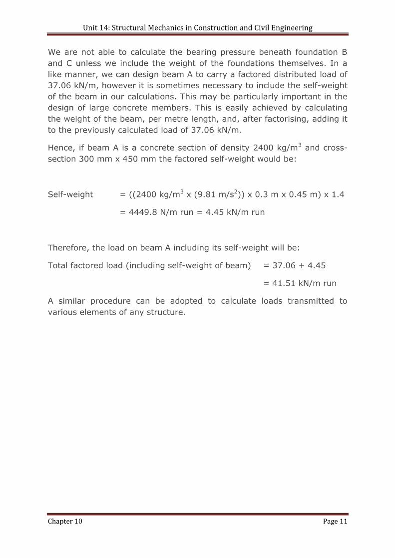
We are not able to calculate the bearing pressure beneath foundation B
and C unless we include the weight of the foundations themselves. In a
like manner, we can design beam A to carry a factored distributed load of
37.06 kN/m, however it is sometimes necessary to include the self-weight
of the beam in our calculations. This may be particularly important in the
design of large concrete members. This is easily achieved by calculating
the weight of the beam, per metre length, and, after factorising, adding it
to the previously calculated load of 37.06 kN/m.
Hence, if beam A is a concrete section of density 2400 kg/m3 and cross-
section 300 mm x 450 mm the factored self-weight would be:
Self-weight = ((2400 kg/m3 x (9.81 m/s2)) x 0.3 m x 0.45 m) x 1.4
= 4449.8 N/m run = 4.45 kN/m run
Therefore, the load on beam A including its self-weight will be:
Total factored load (including self-weight of beam) = 37.06 + 4.45
= 41.51 kN/m run
A similar procedure can be adopted to calculate loads transmitted to
various elements of any structure.
Unit 14: Structural Mechanics in Construction and Civil Engineering
Chapter 10 Page 12
Exercise 10.1
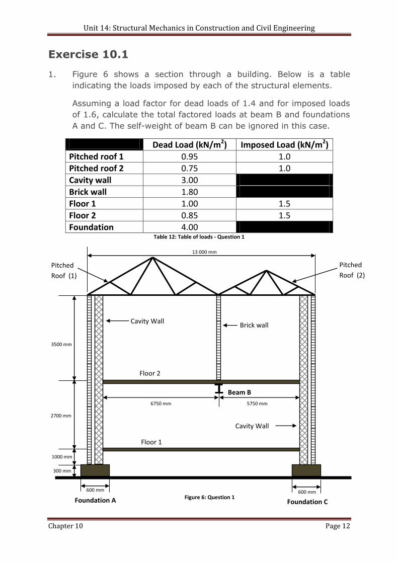
1. Figure 6 shows a section through a building. Below is a table
indicating the loads imposed by each of the structural elements.
Assuming a load factor for dead loads of 1.4 and for imposed loads
of 1.6, calculate the total factored loads at beam B and foundations
A and C. The self-weight of beam B can be ignored in this case.
Dead Load (kN/m2) Imposed Load (kN/m2)
Pitched roof 1 0.95 1.0 Pitched roof 2 0.75 1.0
Cavity wall 3.00
Brick wall 1.80 Floor 1 1.00 1.5
Floor 2 0.85 1.5 Foundation 4.00
Table 12: Table of loads - Question 1
600 mm 600 mm
5750 mm 6750 mm
300 mm
1000 mm
2700 mm
3500 mm
13 000 mm
Pitched
Roof (2)
Cavity Wall
Floor 2
Floor 1
Brick wall
Foundation A
Beam B
Foundation C
Cavity Wall
Pitched
Roof (1)
Figure 6: Question 1
Unit 14: Structural Mechanics in Construction and Civil Engineering
Chapter 10 Page 13
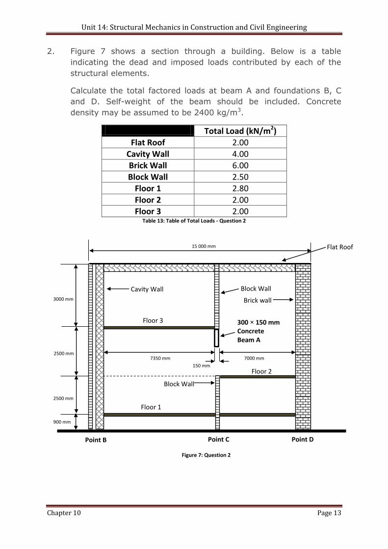
2. Figure 7 shows a section through a building. Below is a table
indicating the dead and imposed loads contributed by each of the
structural elements.
Calculate the total factored loads at beam A and foundations B, C
and D. Self-weight of the beam should be included. Concrete
density may be assumed to be 2400 kg/m3.
Total Load (kN/m2)
Flat Roof 2.00
Cavity Wall 4.00 Brick Wall 6.00
Block Wall 2.50 Floor 1 2.80
Floor 2 2.00 Floor 3 2.00
Table 13: Table of Total Loads - Question 2
Block Wall
7000 mm 7350 mm
900 mm
2500 mm
2500 mm
3000 mm
15 000 mm Flat Roof
Cavity Wall
Floor 3
Floor 1
Brick wall
Point B
300 × 150 mm Concrete Beam A
Block Wall
150 mm Floor 2
Point C Point D
Figure 7: Question 2
Unit 14: Structural Mechanics in Construction and Civil Engineering
Chapter 10 Page 14
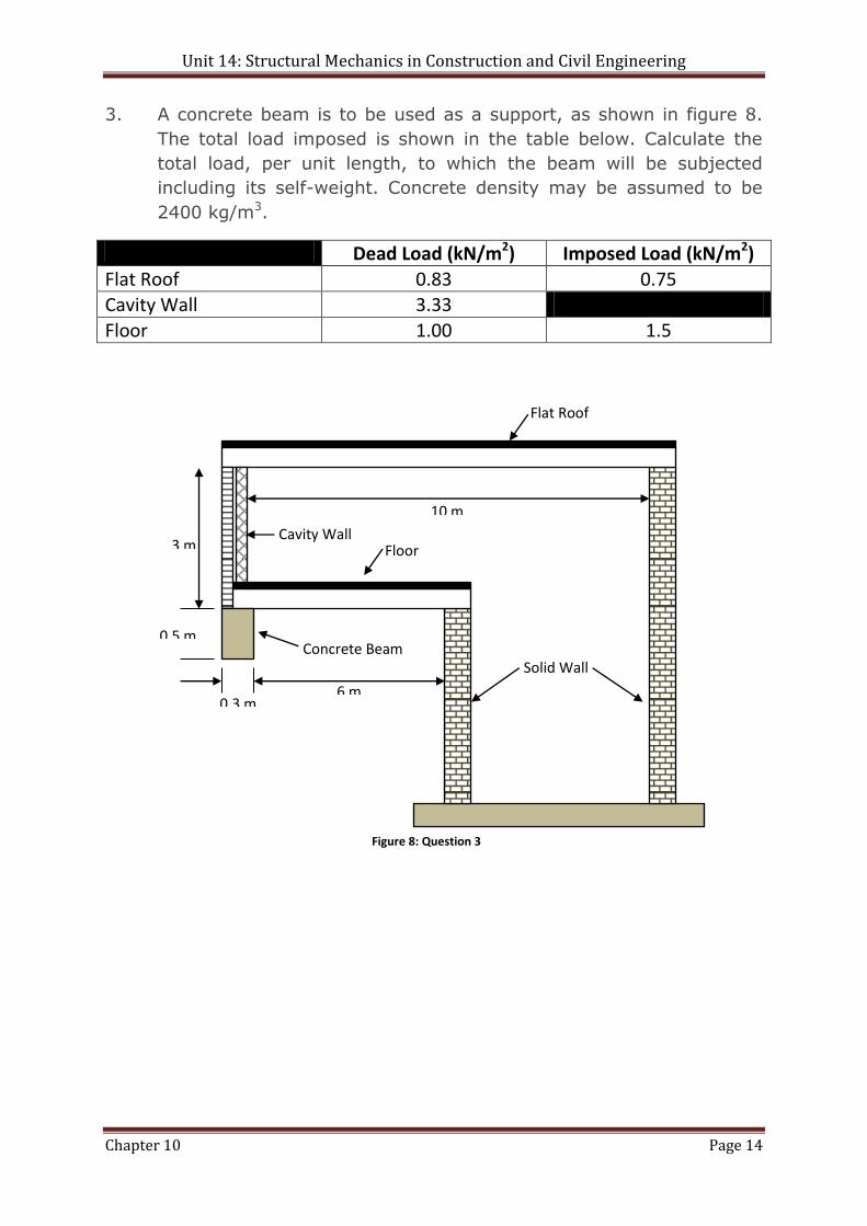
3. A concrete beam is to be used as a support, as shown in figure 8.
The total load imposed is shown in the table below. Calculate the
total load, per unit length, to which the beam will be subjected
including its self-weight. Concrete density may be assumed to be
2400 kg/m3.
Dead Load (kN/m2) Imposed Load (kN/m2)
Flat Roof 0.83 0.75 Cavity Wall 3.33
Floor 1.00 1.5
Floor
Flat Roof
Solid Wall Concrete Beam
Cavity Wall
10 m
3 m
0.5 m
0.3 m 6 m
Figure 8: Question 3