Embed Size (px)
Citation preview
1
ECE 3120 Microelectronics II Dr. Suketu Naik
Chapter 10
Feedback
2
ECE 3120 Microelectronics II Dr. Suketu Naik
Operational Amplifier Circuit Components
1. Ch 7: Current Mirrors and Biasing
2. Ch 9: Frequency Response
3. Ch 8: Active-Loaded Differential Pair
4. Ch 10: Feedback
5. Ch 11: Output Stages
3
ECE 3120 Microelectronics II Dr. Suketu Naik
Basic Feedback Topologies
4
ECE 3120 Microelectronics II Dr. Suketu Naik
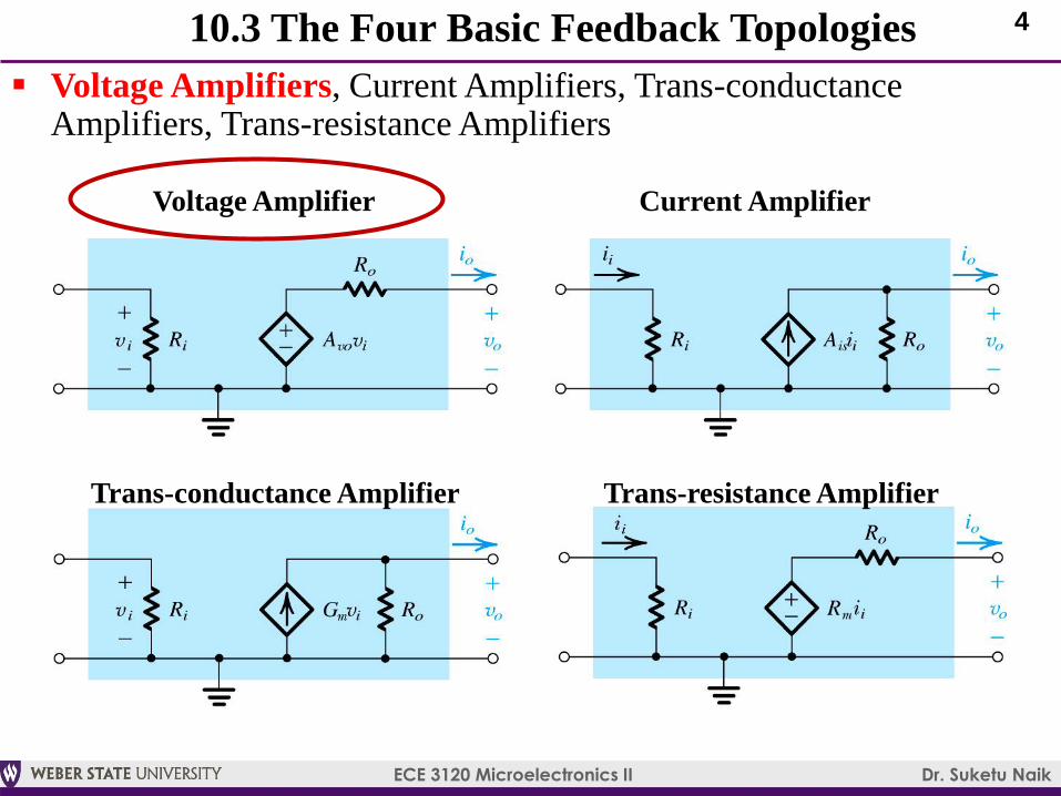
10.3 The Four Basic Feedback Topologies
Voltage Amplifiers, Current Amplifiers, Trans-conductance Amplifiers, Trans-resistance Amplifiers
Voltage Amplifier Current Amplifier
Trans-conductance Amplifier Trans-resistance Amplifier
5
ECE 3120 Microelectronics II Dr. Suketu Naik
Feedback Voltage Amplifier
(Series-Shunt Feedback)
6
ECE 3120 Microelectronics II Dr. Suketu Naik
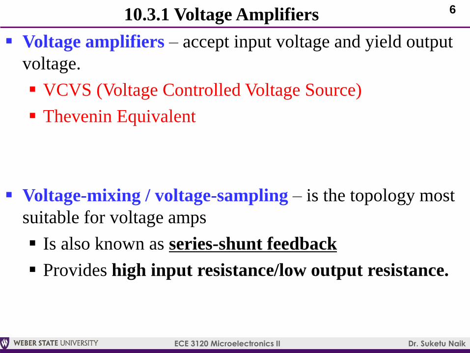
10.3.1 Voltage Amplifiers
Voltage amplifiers – accept input voltage and yield output
voltage.
VCVS (Voltage Controlled Voltage Source)
Thevenin Equivalent
Voltage-mixing / voltage-sampling – is the topology most
suitable for voltage amps
Is also known as series-shunt feedback
Provides high input resistance/low output resistance.
7
ECE 3120 Microelectronics II Dr. Suketu Naik
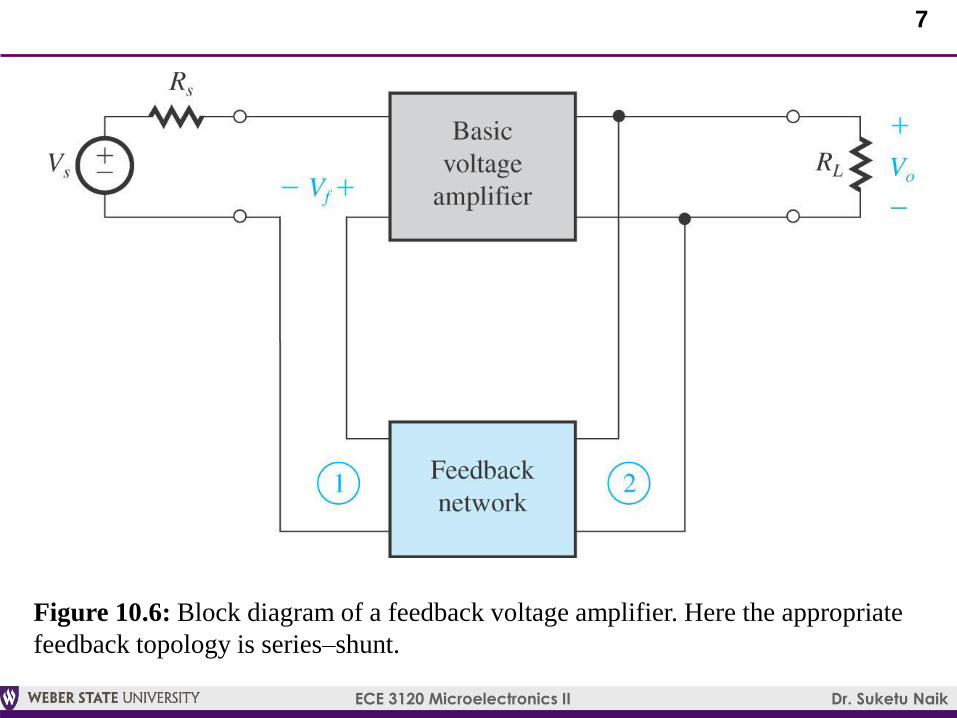
Figure 10.6: Block diagram of a feedback voltage amplifier. Here the appropriate
feedback topology is series–shunt.
8
ECE 3120 Microelectronics II Dr. Suketu Naik
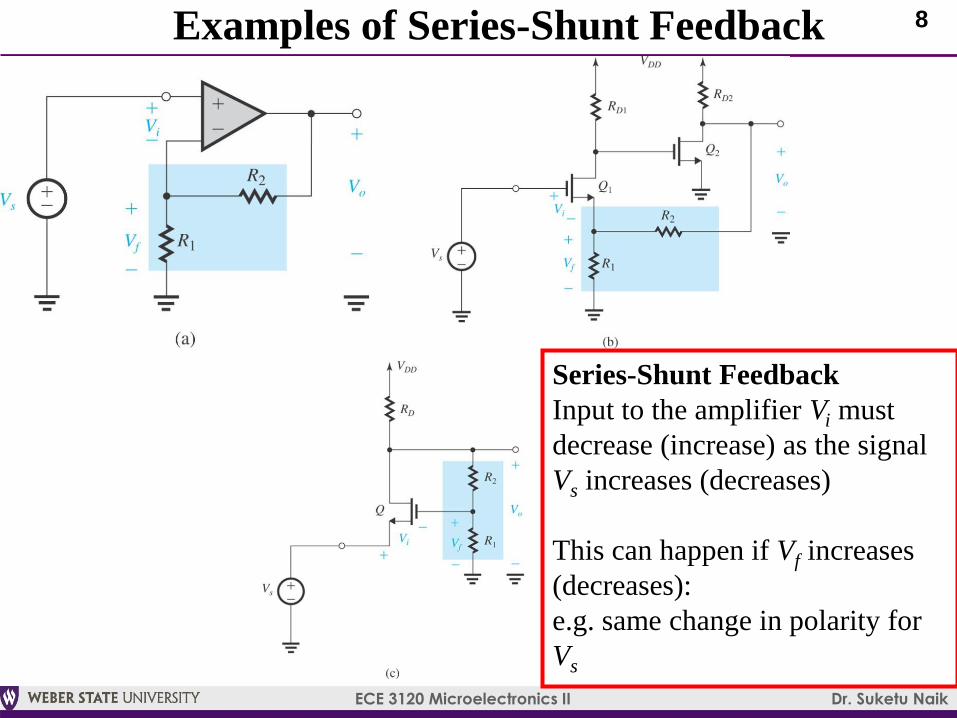
Examples of Series-Shunt Feedback
Series-Shunt Feedback
Input to the amplifier Vi must
decrease (increase) as the signal
Vs increases (decreases)
This can happen if Vf increases
(decreases):
e.g. same change in polarity for
Vs
9
ECE 3120 Microelectronics II Dr. Suketu Naik
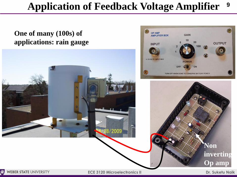
Application of Feedback Voltage Amplifier
One of many (100s) of
applications: rain gauge
Non
inverting
Op amp
10
ECE 3120 Microelectronics II Dr. Suketu Naik
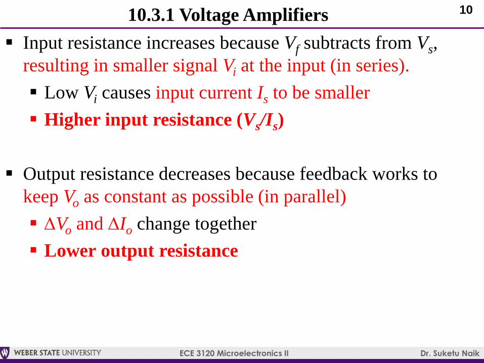
Input resistance increases because Vf subtracts from Vs,
resulting in smaller signal Vi at the input (in series).
Low Vi causes input current Is to be smaller
Higher input resistance (Vs/Is)
Output resistance decreases because feedback works to
keep Vo as constant as possible (in parallel)
DVo and DIo change together
Lower output resistance
10.3.1 Voltage Amplifiers
11
ECE 3120 Microelectronics II Dr. Suketu Naik
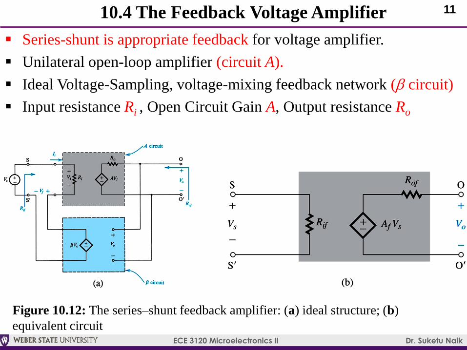
10.4 The Feedback Voltage Amplifier
Series-shunt is appropriate feedback for voltage amplifier.
Unilateral open-loop amplifier (circuit A).
Ideal Voltage-Sampling, voltage-mixing feedback network (b circuit)
Input resistance Ri , Open Circuit Gain A, Output resistance Ro
Figure 10.12: The series–shunt feedback amplifier: (a) ideal structure; (b)
equivalent circuit
12
ECE 3120 Microelectronics II Dr. Suketu Naik
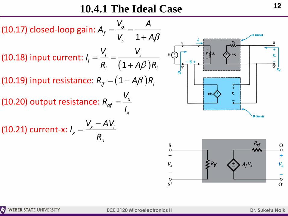
10.4.1 The Ideal Case
(10.17) closed-loop gain:
(10.18) input current:
(10.19) input resistance:
(10.20) output resistance:
(10.21) current-x:
1
1
1
of
s
sii
i i
if i
xof
x
x ix
o
V AA
V A
VVI
R A R
R A R
VR
I
V AVI
R
b
b
b
13
ECE 3120 Microelectronics II Dr. Suketu Naik
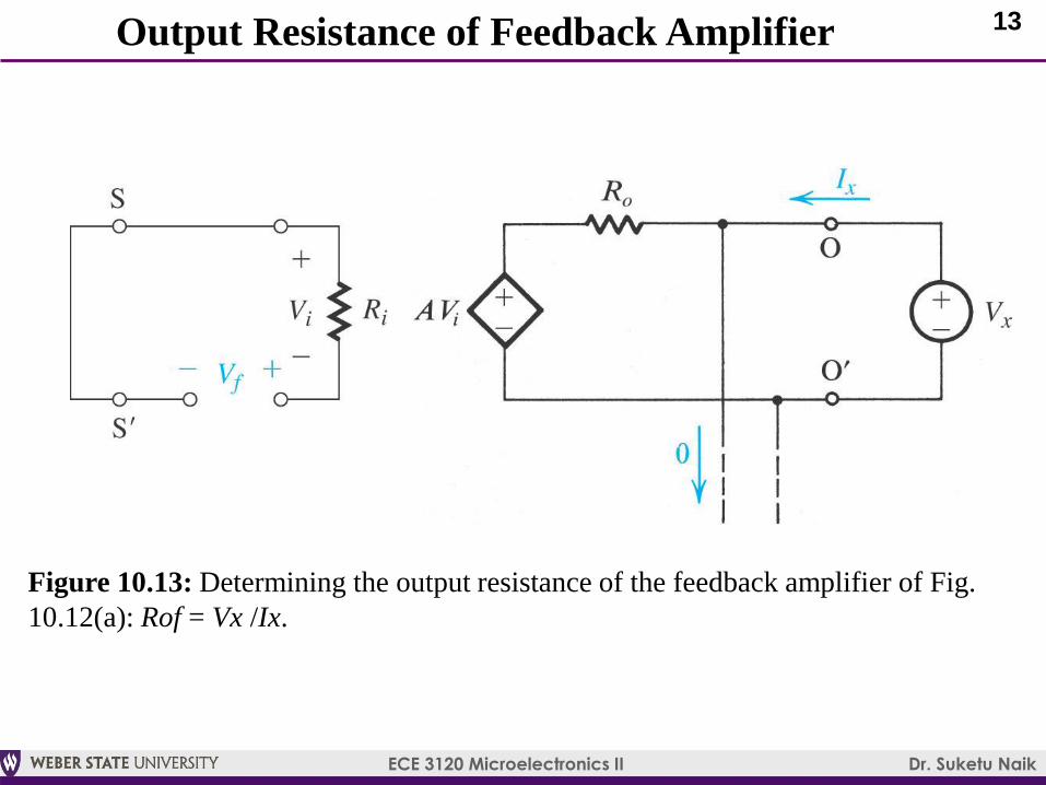
Figure 10.13: Determining the output resistance of the feedback amplifier of Fig.
10.12(a): Rof = Vx /Ix.
Output Resistance of Feedback Amplifier
14
ECE 3120 Microelectronics II Dr. Suketu Naik
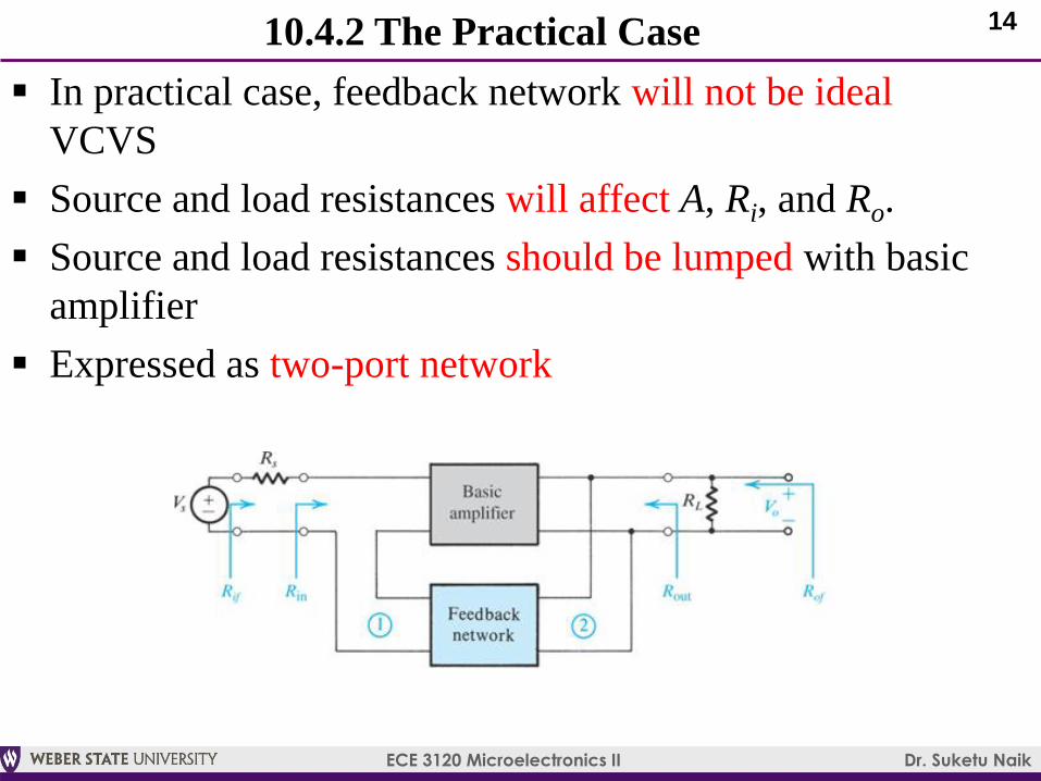
10.4.2 The Practical Case
In practical case, feedback network will not be ideal
VCVS
Source and load resistances will affect A, Ri, and Ro.
Source and load resistances should be lumped with basic
amplifier
Expressed as two-port network
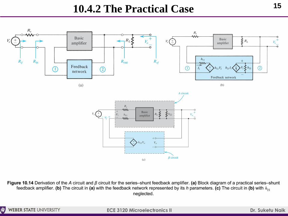
15
ECE 3120 Microelectronics II Dr. Suketu Naik
10.4.2 The Practical Case
16
ECE 3120 Microelectronics II Dr. Suketu Naik
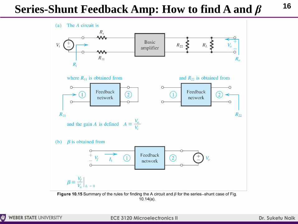
Series-Shunt Feedback Amp: How to find A and β
17
ECE 3120 Microelectronics II Dr. Suketu Naik
10.4.3 Summary
Ri and Ro are the input and output resistances, respectively, of the A circuit in Figure 10.15(a)
Rif and Rof are the input and output resistances, respectively, of the feedback amplifier, including Rs and RL (see Figure 10.14a)
The actual input and output resistances of the feedback amplifier exclude Rs and RL. These are denoted Rin and Rout in Figure 10.14(a) and can be determined via equations (10.25) and (10.25)
18
ECE 3120 Microelectronics II Dr. Suketu Naik
List of Problems
Feedback Voltage Amplifier:
expl10.4 (read-only): Series-shunt feedback amplifier
p10.31: Series-shunt feedback amplifier
p10.36 (simulation only): Series-shunt feedback amplifier
with BJTs
p10.39 (simulation only): Series-shunt feedback in active-
loaded differential amplifier with MOSFETs


![Inductance, Capacitance, and Mutual Inductancefaculty.weber.edu/snaik/ECE1270/Ch6.pdfInductance, Capacitance, and Mutual Inductance Assessment Problems AP 6.1 [a] ig = 8e−300t −](https://img.pdfslide.net/doc/110x75/5f0246127e708231d4037222/inductance-capacitance-and-mutual-inductance-capacitance-and-mutual-inductance.jpg)