Embed Size (px)
Citation preview
Cis78-19286-02
C H A P T E R 10
Manage AlarmsNote The terms "Unidirectional Path Switched Ring" and "UPSR" may appear in Cisco literature. These terms do not refer to using Cisco ONS 15xxx products in a unidirectional path switched ring configuration. Rather, these terms, as well as "Path Protected Mesh Network" and "PPMN," refer generally to Cisco's path protection feature, which may be used in any topological network configuration. Cisco does not recommend using its path protection feature in any particular topological network configuration.
This chapter contains the procedures for viewing and managing the alarms and conditions on a Cisco ONS 15454.
Cisco Transport Controller (CTC) detects and reports alarms generated by the Cisco ONS 15454 and the Optical Networking System (ONS) network. You can use CTC to monitor and manage alarms at card, node, or network level. You can also view alarm counts on the LCD front panel.
Note The procedures and tasks described in this chapter for the Cisco ONS 15454 platform is applicable to the Cisco ONS 15454 M2 and Cisco ONS 15454 M6 platforms, unless noted otherwise.
Note Unless otherwise specified, “ONS 15454” refers to both ANSI and ETSI shelf assemblies.
Before You BeginThis section lists the chapter procedures (NTPs). Turn to a procedure for applicable tasks (DLPs).
1. NTP-G63 Document Existing Provisioning, page 10-2—Complete this procedure as needed to print or export node data.
2. NTP-G64 View Alarms, History, Events, and Conditions, page 10-6—Complete this procedure as needed to see alarms and conditions occurring on the node and a complete history of alarm and condition messages.
3. NTP-G65 Delete Cleared Alarms from Display, page 10-14—Complete this procedure as needed to delete cleared alarm information.
4. NTP-G66 View Alarm-Affected Circuits, page 10-15—Complete this procedure as needed to find circuits that are affected by a particular alarm or condition.
5. NTP-G67 View Alarm Counts on the LCD for a Node, Shelf, Slot, or Port, page 10-15—Complete this procedure as needed to see a statistical count of alarms that have occurred for a slot or port.
10-1co ONS 15454 DWDM Procedure Guide, Release 9.2
Chapter 10 Manage AlarmsBefore You Begin
6. NTP-G68 Create, Download, and Assign Alarm Severity Profiles, page 10-17—Complete this procedure as needed to change the default severity for certain alarms, to assign the new severities to a port, card, or node, and to delete alarm profiles.
7. NTP-G69 Enable, Modify, or Disable Alarm Severity Filtering, page 10-24—Complete this procedure as needed to enable, disable, or modify alarm severity filtering in the Conditions, Alarms, or History screens at the node or network level.
8. NTP-G70 Suppress Alarms or Discontinue Alarm Suppression, page 10-27—Complete this procedure as needed to suppress reported alarms at the port, card, or node level and to disable the suppress command to resume normal alarm reporting.
9. NTP-G72 Provision External Alarms and Controls on the Alarm Interface Controller-International Card, page 10-30—Complete this procedure as needed to provision external alarms and controls on the Alarm Interface Controller–International (AIC-I) card.
10. NTP-G277 Provision Alarms and Controls on the TNC or TSC Card, page 10-32 —Complete this procedure as needed to provision external alarms and controls on the TNC or TSC card.
NTP-G63 Document Existing Provisioning
Step 1 Complete the “DLP-G46 Log into CTC” task on page 3-30 at the node where you want to print or export data. If you are already logged in, continue with Step 2.
Step 2 As needed, complete the “DLP-G113 Print CTC Data” task on page 10-3.
Step 3 As needed, complete the “DLP-G114 Export CTC Data” task on page 10-4.
Stop. You have completed this procedure.
Purpose Use this procedure to document existing provisioning by printing or exporting card, node, or network CTC information. You can export information as delineated text files to other applications. This procedure is useful for network record keeping and troubleshooting.
Tools/Equipment A printer connected to the CTC computer by a direct or network connection
Prerequisite Procedures Chapter 4, “Turn Up a Node”
Required/As needed As needed
Onsite/Remote Onsite or remote
Security Level Retrieve or higher
10-2Cisco ONS 15454 DWDM Procedure Guide, Release 9.2
78-19286-02
Chapter 10 Manage AlarmsBefore You Begin
DLP-G113 Print CTC Data
Step 1 Click the tab (and subtab, if present) containing the information you want to print. For example, click the Alarms tab to print Alarms window data.
The print operation is available for all network, node, and card view windows.
Step 2 From the File menu choose Print. The Print dialog box appears.
Step 3 In the Print dialog box, click a printing option:
• Entire Frame—Prints the entire CTC window including the graphical view of the card, node, or network. This option is available for all windows.
• Tabbed View—Prints the lower half of the CTC window containing tabs and data. The printout includes the selected tab (on top) and the data shown in the tab window. For example, if you print the History window Tabbed View, you print only history items appearing in the window. This option is available for all windows.
• Table Contents—Prints CTC data in table format without graphical representations of shelves, cards, or tabs. This option applies to all windows except:
– N ode view (single-shelf mode) or multishelf view (multishelf mode) Provisioning > General > General, Multishelf Config, and Power Monitor windows
– Node view (single-shelf mode) or multishelf view (multishelf mode) Provisioning > Network > General window
– Node view (single-shelf mode) or multishelf view (multishelf mode) Provisioning > Security > Policy, Access, Data Comm, and Legal Disclaimer windows
– Node view (single-shelf mode) or multishelf view (multishelf mode) Provisioning > SNMP window
– Node view (single-shelf mode) or shelf view (multishelf mode) Provisioning > Timing window > General and BITS Facilities windows
– Node view (single-shelf mode) or multishelf view (multishelf mode) Provisioning > OSI > Main Setup window
– Node view (single-shelf mode) or multishelf view (multishelf mode) Provisioning > OSI > TARP > Config window
– Node view (single-shelf mode) or multishelf view (multishelf mode) Provisioning > Comm Channels > LMP > General window
– Node view (single-shelf mode) or multishelf view (multishelf mode) Provisioning > WDM-ANS > Node Setup window
– Node view (single-shelf mode) or shelf view (multishelf mode) Maintenance > Overhead XConnect window
Purpose This task prints CTC card, node, or network data in graphical or tabular format on a Windows-provisioned printer.
Tools/Equipment Printer connected to the CTC computer by a direct or network connection
Prerequisite procedures DLP-G46 Log into CTC, page 3-30
Required/As needed As needed
Onsite/Remote Onsite or remote
Security Level Retrieve or higher
10-3Cisco ONS 15454 DWDM Procedure Guide, Release 9.2
78-19286-02
Chapter 10 Manage AlarmsBefore You Begin
– Node view (single-shelf mode) or multishelf view (multishelf mode) Maintenance > Database window
– Node view (single-shelf mode), multishelf view (multishelf mode), or shelf view (multishelf mode) Maintenance > Diagnostic window
– Node view (single-shelf mode) or shelf view (multishelf mode) Maintenance > Protection window
– Node view (single-shelf mode) or shelf view (multishelf mode) Maintenance > Timing > Source window
– Node view (single-shelf mode) or shelf view (multishelf mode) Maintenance > DWDM > ROADM Power Monitoring window
The Table Contents option prints all the data contained in a table and the table column headings. For example, if you print the History window Table Contents view, you print all data included in the table whether or not items appear in the window.
Tip When you print using the Tabbed View option, it can be difficult to distinguish whether the printout applies to the network, node, or card view. To determine the view, compare the tabs on the printout. The network, node, and card views are identical except that network view does not contain an Inventory tab or Performance tab.
Step 4 Click OK.
Step 5 In the Windows Print dialog box, click a printer and click OK.
Step 6 Repeat this task for each window that you want to print.
Step 7 Return to your originating procedure (NTP).
DLP-G114 Export CTC Data
Step 1 Click the tab containing the information you want to export (for example, the Alarms tab or the Circuits tab).
Step 2 If you want to export detailed circuit information, complete the following:
a. In the Circuits window, choose a circuit and click Edit to open it in the Edit Circuits window.
b. In the Edit Circuits window, choose the desired tab: Drops, Path Protection/SNCP Selectors, Path Protection/SNCP Switch Counts, State, or Merge.
Purpose This task exports CTC table data as delineated text to view or edit the data in text editor, word processing, spreadsheet, database management, or web browser applications.
Tools/Equipment None
Prerequisite procedures DLP-G46 Log into CTC, page 3-30
Required/As needed As needed
Onsite/Remote Onsite or remote
Security Level Retrieve or higher
10-4Cisco ONS 15454 DWDM Procedure Guide, Release 9.2
78-19286-02
Chapter 10 Manage AlarmsBefore You Begin
Note Depending upon your configuration, you may or may not see all of the above tabs when you click Edit.
Step 3 Choose Export from the File menu. The Export dialog box appears.
Step 4 In the Export dialog box, click a data format:
• As HTML—Saves data as a simple HTML table file without graphics. The file must be viewed or edited with applications such as Microsoft Internet Explorer or other applications capable of opening HTML files.
• As CSV—Saves the CTC table as comma-separated values (CSV). This option does not apply to the Node view (single-shelf mode) or shelf view (multishelf mode) Maintenance > Timing > Report window.
• As TSV—Saves the CTC table as tab-separated values (TSV).
Step 5 If you want to open a file in a text editor or word processor application, procedures will vary. Typically, you can use the File > Open command to view the CTC data, or you can double-click the file name and choose an application such as Notepad.
Text editor and word processor applications format the data exactly as it is exported, including comma or tab separators. All applications that open the data files allow you to format the data.
Step 6 If you want to open the file in spreadsheet and database management applications, procedures will vary. Typically, you need to open the application and choose File > Import, then choose a delimited file to format the data in cells.
Spreadsheet and database management programs also allow you to manage the exported data.
Note An exported file cannot be opened in CTC.
The export operation applies to all tabular data except:
• Node view (single-shelf mode) or multishelf view (multishelf mode) Provisioning > General > General, Multishelf Config, and Power Monitor windows
• Node view (single-shelf mode) or multishelf view (multishelf mode) Provisioning > Network > General window
• Node view (single-shelf mode) or multishelf view (multishelf mode) Provisioning > Security > Policy, Access, Data Comm, and Legal Disclaimer windows
• Provisioning > SNMP window
• Node view (single-shelf mode) or shelf view (multishelf mode) Provisioning > Timing > General and BITS Facilities windows
• Node view (single-shelf mode) or multishelf view (multishelf mode) Provisioning > OSI > Main Setup window
• Node view (single-shelf mode) or multishelf view (multishelf mode) Provisioning > OSI > TARP > Config window
• Node view (single-shelf mode) or multishelf view (multishelf mode) Provisioning > WDM-ANS > Node Setup window
• Node view (single-shelf mode) or multishelf view (multishelf mode) Provisioning > Comm Channels > LMP > General window
10-5Cisco ONS 15454 DWDM Procedure Guide, Release 9.2
78-19286-02
Chapter 10 Manage AlarmsBefore You Begin
• Node view (single-shelf mode) or shelf view (multishelf mode) Maintenance > Overhead XConnect window
• Node view (single-shelf mode) or multishelf view (multishelf mode) Maintenance > Database window
• Node view (single-shelf mode), multishelf view (multishelf mode), or shelf view (multishelf mode) Maintenance > Diagnostic window
• Node view (single-shelf mode) or shelf view (multishelf mode) Maintenance > Protection window
• Node view (single-shelf mode) or shelf view (multishelf mode) Maintenance > Timing > Source windows
• Node view (single-shelf mode) or multishelf view (multishelf mode) Maintenance > DWDM > ROADM Power Monitoring window [ETSI only]
Step 7 Click OK.
Step 8 In the Save dialog box, enter a name in the File name field using one of the following formats:
• filename.html for HTML files
• filename.csv for CSV files
• filename.tsv for TSV files
Step 9 Navigate to a directory where you want to store the file.
Step 10 Click Save.
Step 11 Repeat the task for each window that you want to export.
Step 12 Return to your originating procedure (NTP).
NTP-G64 View Alarms, History, Events, and Conditions
Step 1 Complete the “DLP-G46 Log into CTC” task on page 3-30. If you are already logged in, continue with Step 2.
Step 2 Complete the “DLP-G115 View Alarms” task on page 10-7 as needed.
Step 3 Complete the “DLP-G116 View Alarm or Event History” task on page 10-8 as needed.
Step 4 Complete the “DLP-G117 Change the Maximum Number of Session Entries for Alarm History” task on page 10-10 as needed.
Step 5 Complete the “DLP-G118 Display Alarms and Conditions Using Time Zone” task on page 10-11 as needed.
Purpose Use this procedure to view current or historical alarms and conditions for a card, node, or network. This information is useful for monitoring and troubleshooting hardware and software events.
Tools/Equipment None
Prerequisite Procedures Chapter 3, “Connect the PC and Log into the GUI”
Required/As Needed As needed
Onsite/Remote Onsite or remote
Security Level Provisioning or higher
10-6Cisco ONS 15454 DWDM Procedure Guide, Release 9.2
78-19286-02
Chapter 10 Manage AlarmsBefore You Begin
Step 6 Complete the “DLP-G119 Synchronize Alarms” task on page 10-12 as needed.
Step 7 Complete the “DLP-G120 View Conditions” task on page 10-12 as needed.
Stop. You have completed this procedure.
DLP-G115 View Alarms
Step 1 In card, node (single-shelf mode) or shelf view (multishelf mode), or network view, click the Alarms tab to view the alarms for that card, node, shelf, or network.
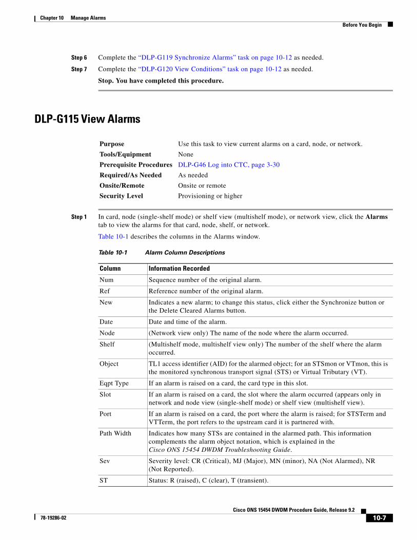
Table 10-1 describes the columns in the Alarms window.
Purpose Use this task to view current alarms on a card, node, or network.
Tools/Equipment None
Prerequisite Procedures DLP-G46 Log into CTC, page 3-30
Required/As Needed As needed
Onsite/Remote Onsite or remote
Security Level Provisioning or higher
Table 10-1 Alarm Column Descriptions
Column Information Recorded
Num Sequence number of the original alarm.
Ref Reference number of the original alarm.
New Indicates a new alarm; to change this status, click either the Synchronize button or the Delete Cleared Alarms button.
Date Date and time of the alarm.
Node (Network view only) The name of the node where the alarm occurred.
Shelf (Multishelf mode, multishelf view only) The number of the shelf where the alarm occurred.
Object TL1 access identifier (AID) for the alarmed object; for an STSmon or VTmon, this is the monitored synchronous transport signal (STS) or Virtual Tributary (VT).
Eqpt Type If an alarm is raised on a card, the card type in this slot.
Slot If an alarm is raised on a card, the slot where the alarm occurred (appears only in network and node view (single-shelf mode) or shelf view (multishelf view).
Port If an alarm is raised on a card, the port where the alarm is raised; for STSTerm and VTTerm, the port refers to the upstream card it is partnered with.
Path Width Indicates how many STSs are contained in the alarmed path. This information complements the alarm object notation, which is explained in the Cisco ONS 15454 DWDM Troubleshooting Guide.
Sev Severity level: CR (Critical), MJ (Major), MN (minor), NA (Not Alarmed), NR (Not Reported).
ST Status: R (raised), C (clear), T (transient).
10-7Cisco ONS 15454 DWDM Procedure Guide, Release 9.2
78-19286-02
Chapter 10 Manage AlarmsBefore You Begin
Table 10-2 lists the color codes for node alarm and condition severities.
Step 2 If alarms are present, refer to the Cisco ONS 15454 DWDM Troubleshooting Guide for information and troubleshooting procedures.
Step 3 Return to your originating procedure (NTP).
DLP-G116 View Alarm or Event History
SA When checked, indicates a service-affecting alarm.
Cond The error message/alarm name; these names are alphabetically defined in the Cisco ONS 15454 Troubleshooting DWDM Guide.
Description Description of the alarm.
Wavelength The channel wavelength the alarm is related to. It is applicable to OCH port only.
Direction —
Location Indicates if an alarm is local to the interface (NE = Near End) or is propagated from remote (FE = Far End).
Table 10-1 Alarm Column Descriptions (continued)
Column Information Recorded
Table 10-2 Color Codes for Node Alarms and Condition Severities
Color Description
Red Raised Critical (CR) alarm
Orange Raised Major (MJ) alarm
Yellow Raised Minor (MN) alarm
Magenta (pink) Raised Not Alarmed (NA) condition
Blue Raised Not Reported (NR) condition
White Cleared (C) alarm or condition
Purpose This task is used to view past cleared and uncleared ONS 15454 alarm messages at the card, node, or network level. This task is useful for troubleshooting configuration, traffic, or connectivity issues that are indicated by alarms.
Tools/Equipment None
Prerequisite Procedures DLP-G46 Log into CTC, page 3-30
Required/As Needed As neededOnsite/Remote Onsite or remoteSecurity Level Retrieve or higher
10-8Cisco ONS 15454 DWDM Procedure Guide, Release 9.2
78-19286-02
Chapter 10 Manage AlarmsBefore You Begin
Step 1 Decide whether you want to view the alarm message history at the Network, node (single-shelf mode), multishelf (multishelf mode), shelf (multishelf mode), or card level.
Step 2 To view alarm history for a single-shelf node:
a. In node view, click the History > Session tabs to view the alarms and conditions (events) raised during the current session.
b. Click the History > Shelf tabs.
If you check the Alarms check box, the node alarm history appears. If you check the Events check box, the node Not Alarmed and transient event history appears. If you check both check boxes, you will retrieve shelf history for alarms and events.
c. Click Retrieve to view all available messages for the History > Shelf tab.
Note Alarms can be unreported when they are filtered out of the display using the Filter button in either tab. See the “DLP-G126 Enable Alarm Filtering” task on page 10-25 for information.
Tip Double-click an alarm in the alarm table or an event (condition) message in the history table to display the view that corresponds to the alarm message. For example, double-clicking a card alarm or event takes you to card view. In network view, double-clicking a node alarm or event takes you to node view.
Step 3 To view alarm history for a multishelf node:
a. In multishelf view, click the History > Session tabs to view the alarms and conditions (events) raised during the current session for the multishelf.
b. Click the History > Node tabs.
If you check the Alarms check box, the multishelf alarm history appears. If you check the Events check box, the multishelf Not Alarmed and transient event history appears. If you check both check boxes, you will retrieve the node history for alarms and events.
c. Click Retrieve to view all available messages for the History > Node tab.
Step 4 To view alarm history for a shelf within a multishelf:
a. In shelf view, click the History > Session tabs to view the alarms and conditions (events) raised during the current session for the shelf.
b. Click the History > Shelf tabs.
If you check the Alarms check box, the shelf alarm history appears. If you check the Events check box, the shelf Not Alarmed and transient event history appears. If you check both check boxes, you will retrieve the shelf history for alarms and events.
c. Click Retrieve to view all available messages for the History > Shelf tab.
Step 5 To view network alarm history:
a. From the View menu, choose Go to Network View.
b. Click the History tab.
Alarms and conditions (events) raised during the current session appear.
10-9Cisco ONS 15454 DWDM Procedure Guide, Release 9.2
78-19286-02
Chapter 10 Manage AlarmsBefore You Begin
Step 6 To view card alarm history:
a. From the View menu, choose Go to Network View. Right-click the node with the card you wish to view and select Open Node.
b. If the node is a multishelf, double-click the shelf containing the card you want to view. If it is a single shelf, continue with Step c.
c. Double-click a card on the shelf graphic to open the card-level view. TCC2/TCC2P/TCC3/TSC cards do not have a card view.
d. Click the History > Session tabs to view the alarm messages raised during the current session.
e. Click the History > Card tabs to retrieve all available alarm messages for the card and click Retrieve.
If you check the Alarms check box, the node alarm history appears. If you check the Events check box, the Not Alarmed and transient event history appears. If you check both boxes, node history for both alarms and events appears.
Note The ONS 15454 can store up to 640 critical alarm messages, 640 major alarm messages, 640 minor alarm messages, and 640 condition messages. When any of these limits is reached, the ONS 15454 discards the oldest events in that category.
Raised and cleared alarm messages (and events, if selected) appear.
Step 7 Return to your originating procedure (NTP).
DLP-G117 Change the Maximum Number of Session Entries for Alarm History
Step 1 From the CTC Edit menu, choose Preferences.
The CTC Preferences dialog box appears (Figure 10-1).
Purpose This task changes the maximum number of session entries included in the alarm history. Use this task to expand the history list to save information for future reference or troubleshooting.
Tools/Equipment None
Prerequisite Procedures DLP-G46 Log into CTC, page 3-30
Required/As Needed As neededOnsite/Remote Onsite or remoteSecurity Level Provisioning or higher
10-10Cisco ONS 15454 DWDM Procedure Guide, Release 9.2
78-19286-02
Chapter 10 Manage AlarmsBefore You Begin
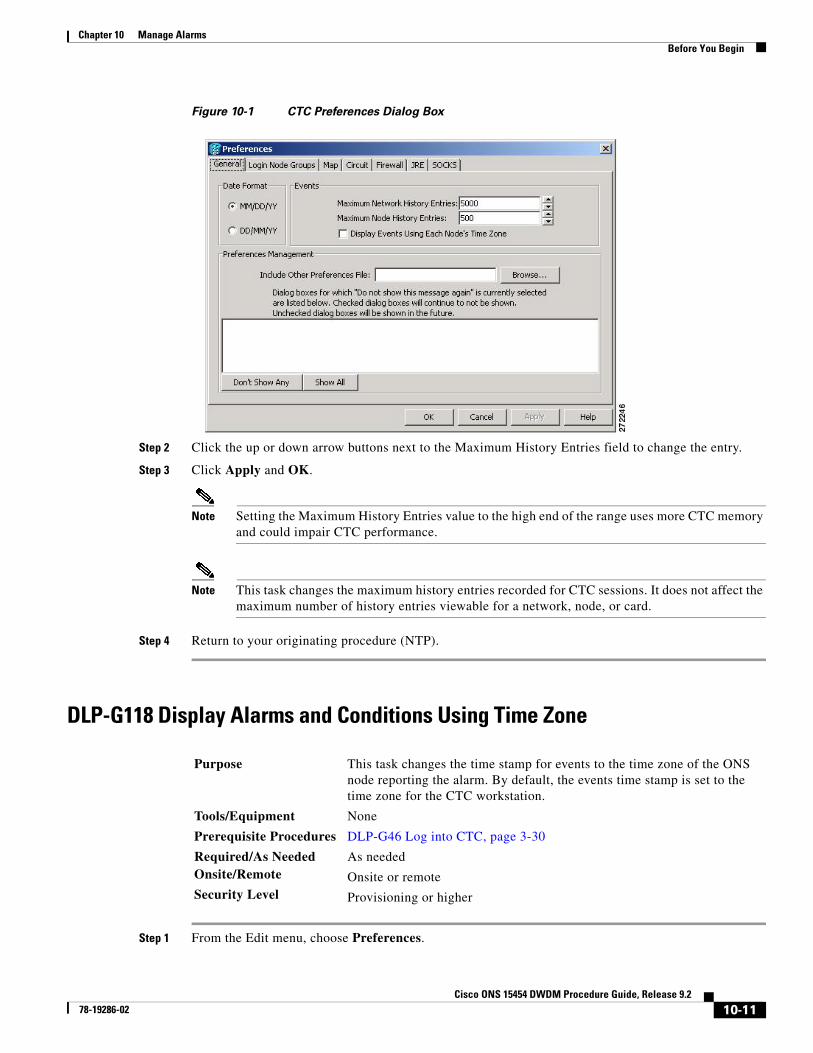
Figure 10-1 CTC Preferences Dialog Box
Step 2 Click the up or down arrow buttons next to the Maximum History Entries field to change the entry.
Step 3 Click Apply and OK.
Note Setting the Maximum History Entries value to the high end of the range uses more CTC memory and could impair CTC performance.
Note This task changes the maximum history entries recorded for CTC sessions. It does not affect the maximum number of history entries viewable for a network, node, or card.
Step 4 Return to your originating procedure (NTP).
DLP-G118 Display Alarms and Conditions Using Time Zone
Step 1 From the Edit menu, choose Preferences.
Purpose This task changes the time stamp for events to the time zone of the ONS node reporting the alarm. By default, the events time stamp is set to the time zone for the CTC workstation.
Tools/Equipment None
Prerequisite Procedures DLP-G46 Log into CTC, page 3-30
Required/As Needed As neededOnsite/Remote Onsite or remoteSecurity Level Provisioning or higher
10-11Cisco ONS 15454 DWDM Procedure Guide, Release 9.2
78-19286-02
Chapter 10 Manage AlarmsBefore You Begin
The CTC Preferences dialog box appears (Figure 10-1 on page 10-11).
Step 2 Check the Display Events Using Each Node’s Time Zone check box. The Apply button is enabled.
Step 3 Click Apply and OK.
Step 4 Return to your originating procedure (NTP).
DLP-G119 Synchronize Alarms
Step 1 At card, node, or network view, click the Alarms tab.
Step 2 Click Synchronize.
This button causes CTC to retrieve a current alarm summary for the card, node, or network. This step is optional because CTC updates the Alarms window automatically as raise/clear messages arrive from the node.
Note Alarms that have been raised during the session will have a check mark in the Alarms window New column. When you click Synchronize, the check mark disappears.
Step 3 Return to your originating procedure (NTP).
DLP-G120 View Conditions
Step 1 From card, node, or network view, click the Conditions tab.
Purpose This task is used to view ONS 15454 events at the card, node, or network level and to refresh the alarm listing so that you can check for new and cleared alarms and conditions.
Tools/Equipment None
Prerequisite Procedures DLP-G46 Log into CTC, page 3-30
Required/As Needed As needed
Onsite/Remote Onsite or remote
Security Level Retrieve or higher
Purpose This task is used to view conditions (events with a Not Reported [NR] severity) at the card, node, or network level. Conditions give you a clear record of changes or events that do not result in alarms.
Tools/Equipment None
Prerequisite Procedures DLP-G46 Log into CTC, page 3-30
Required/As Needed As needed
Onsite/Remote Onsite or remote
Security Level Retrieve or higher
10-12Cisco ONS 15454 DWDM Procedure Guide, Release 9.2
78-19286-02
Chapter 10 Manage AlarmsBefore You Begin
Step 2 Click Retrieve.
The Retrieve button requests the current set of fault conditions from the node, card, or network. The window is not updated when events change on the node. You must click Retrieve to see any changes.
Conditions include all fault conditions raised on the node, whether or not they are reported.
Note Alarms and conditions can be unreported if they are filtered out of the display. See the “DLP-G126 Enable Alarm Filtering” task on page 10-25 for information on filtering.
Events that are reported as Major (MJ), Minor (MN), or Critical (CR) severities are alarms. Events that are reported as Not Alarmed (NA) are conditions. Conditions that are not reported at all are marked Not Reported (NR) in the Conditions window severity column.
Conditions that have a default severity of Critical (CR), Major (MJ), Minor (MN), or Not Alarmed (NA) but are not reported due to exclusion or suppression are shown as NR in the Conditions window.
Note For more information about alarm suppression, see the “DLP-G129 Suppress Alarm Reporting” task on page 10-28.
Current conditions are shown with the severity chosen in the alarm profile, if used. For more information about alarm profiles, see the “NTP-G68 Create, Download, and Assign Alarm Severity Profiles” procedure on page 10-17.
Note When a port is placed in the Out-of-Service and Management, Maintenance (OOS-MA,MT) (ANSI) or Locked-enabled, maintenance (ETSI) service state, it raises an Alarms Suppressed for Maintenance (AS-MT) condition. For information about alarm and condition troubleshooting, refer to the Cisco ONS 15454 DWDM Troubleshooting Guide.
Step 3 If you want to apply exclusion rules, check the Exclude Same Root Cause check box at the node or network view, but do not check the Exclude Same Root Cause check box in card view.
An exclusion rule eliminates all lower-level alarms or conditions that originate from the same cause. For example, a fiber break might cause a loss of signal (LOS) alarm, an alarm indication signal (AIS) condition, and a signal fail (SF) condition. If you check the Exclude Same Root Cause check box, only the LOS alarm will appear. According to Telcordia, exclusion rules apply to a query of “all conditions from a node.”
Step 4 Return to your originating procedure (NTP).
10-13Cisco ONS 15454 DWDM Procedure Guide, Release 9.2
78-19286-02
Chapter 10 Manage AlarmsBefore You Begin
NTP-G65 Delete Cleared Alarms from Display
Step 1 Complete the “DLP-G46 Log into CTC” task on page 3-30. If you are already logged in, continue with Step 2.
Step 2 To delete cleared node-level or multishelf-level alarms:
a. In node view (single-shelf mode) or multishelf view (multishelf mode), click the Alarms tab.
b. Click Delete Cleared Alarms.
– If the Autodelete Cleared Alarms check box is checked, an alarm disappears from the window when it is cleared.
– If the Autodelete Cleared Alarms check box is not checked, an alarm remains in the window when it is cleared. The alarm appears white in the window and has a Clear (CL) severity. The alarm can be removed by clicking the Delete Cleared Alarms button.
This action removes any cleared ONS 15454 alarms from the Alarms tab. The rows of cleared alarms turn white and have a C in their status (ST) column.
Step 3 To delete cleared card-level alarms:
a. In node view (single-shelf mode or multishelf mode), double-click the card graphic for the card you want to open.
b. Click the Alarms tab and then click Delete Cleared Alarms.
– If the Autodelete Cleared Alarms check box is checked, an alarm disappears from the window when it is cleared.
– If the Autodelete Cleared Alarms check box is not checked, an alarm remains in the window when it is cleared. The alarm appears white in the window and has a Clear (CL) severity. The alarm can be removed by clicking the Delete Cleared Alarms button.
Step 4 To delete cleared network-level alarms:
a. In node view, click View > Go to Network View.
b. Click the Alarms tab and then click Delete Cleared Alarms.
– If the Autodelete Cleared Alarms check box is checked, an alarm disappears from the window when it is cleared.
– If the Autodelete Cleared Alarms check box is not checked, an alarm remains in the window when it is cleared. The alarm appears white in the window and has a Clear (CL) severity. The alarm can be removed by clicking the Delete Cleared Alarms button.
Step 5 To remove the transient messages from the History window, click Delete Cleared Alarms. Transient messages are single messages, not raise-and-clear pairs (that is, they do not have companion messages stating that they are cleared).
Purpose Use this procedure to delete Cleared (C) status alarms from the Alarms window or transient messages from the CTC History window.
Tools/Equipment None
Prerequisite Procedures Chapter 3, “Connect the PC and Log into the GUI”
Required/As Needed As needed
Onsite/Remote Onsite or remote
Security Level Retrieve or higher
10-14Cisco ONS 15454 DWDM Procedure Guide, Release 9.2
78-19286-02
Chapter 10 Manage AlarmsBefore You Begin
Stop. You have completed this procedure.
NTP-G66 View Alarm-Affected Circuits
Step 1 Complete the “DLP-G46 Log into CTC” task on page 3-30. If you are already logged in, continue with Step 2.
Step 2 In network, node, shelf, or card view, click the Alarms tab or Conditions tab and then right-click anywhere in the row of an active alarm or condition.
The Select Affected Circuit option appears on the shortcut menu.
Step 3 Left-click or right-click Select Affected Circuits.
The Circuits window appears with the affected OCHNC, OCHCC, or OCH trail highlighted.
Stop. You have completed this procedure.
NTP-G67 View Alarm Counts on the LCD for a Node, Shelf, Slot, or Port
Note In an ONS 15454 M2 shelf assembly, the LCD panel and the Slot, Port, and Status buttons are present on the fan-tray assembly. In an ONS 15454 M6 shelf assembly, the LCD is a separate unit installed above the external connection unit (ECU); the Slot, Port, and Status buttons are present on the LCD unit.
Purpose Use this procedure to view all optical channel network connections (OCHNCs) optical channel client connections (OCHCC), optical channel trail, and ONS 15454 circuits, if any, that are affected by an alarm or condition.
Tools/Equipment None
Prerequisite Procedures NTP-G64 View Alarms, History, Events, and Conditions, page 10-6
Required/As Needed As needed
Onsite/Remote Onsite or remote
Security Level Retrieve or higher
Purpose Use this procedure to view an alarm summary for a node, shelf, slot, or port without using CTC.
Tools/Equipment None
Prerequisite Procedures Chapter 1, “Install the Cisco ONS 15454, ONS 15454 M2, and ONS 15454 M6 Shelf”
Required/As Needed As needed
Onsite/Remote Onsite
Security Level None
10-15Cisco ONS 15454 DWDM Procedure Guide, Release 9.2
78-19286-02
Chapter 10 Manage AlarmsBefore You Begin
Step 1 If you want to view the entire alarm summary:
• For a single shelf node, press either the Slot button or Port button on the LCD panel until “Node” appears on the LCD. You will also see the direction, “Status=Alm Ct.” This means that if you press the Status button at this time, as directed in Step 2, you will see an alarm count for the node.
• For a multishelf node, press the Slot button on the LCD panel on any shelf, until “Shelf” appears on the LCD. Then press the Port button until you see the direction, “Status=Alm Sums.” This means that if you press the Status button at this time, as directed in Step 2, you will see an alarm count for the node.
Step 2 Press the Status button to see a summary of alarms and severities for the node. You will see a message similar to “Alm Ct: 2: MJ:2 MN:2,” meaning that there are two critical alarms, two major alarms, and two minor alarms.
Step 3 If you want to see alarm counts for a particular shelf (node controller or subtending shelf) in a multishelf configuration, press the Slot button on that shelf until “Shelf” appears on the LCD. Then press the Port button until you see the direction, “Status=Alm Ct.”
Step 4 Press the Status button to see a summary of alarms and severities for that particular shelf.
Step 5 If you want to see alarm counts for a particular slot, such as the alarms for an OC-3 card in Slot 3, press the Slot button until you see “Slot-3” on the LCD. You will see the direction, “Status=Alm Ct Sum.”
Step 6 Press the Status button to see a summary of alarms and severities against the slot. For example, you might see “Slot-3 Alm Sum:0 MJ:1 MN:2.” This means that there are no critical alarms, one major alarm, and two minor alarms against the slot.
Step 7 If you want to view the alarms against a port on the card, such as Port 3 of the OC-3 card you viewed previously, press the Port button until you see “Port-3 Status=Alm Ct.”
Step 8 Press Status to view alarm counts against the port. You will see a message similar to “Slot-3 Port-0 Ct:0 MJ:1 MN:0.” This means that there is one major alarm against this port.
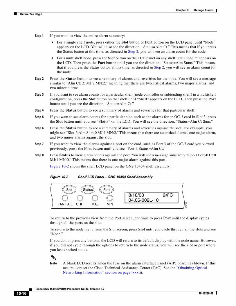
Figure 10-2 shows the shelf LCD panel on the ONS 15454 shelf assembly.
Figure 10-2 Shelf LCD Panel—ONS 15454 Shelf Assembly
To return to the previous view from the Port screen, continue to press Port until the display cycles through all the ports on the slot.
To return to the node menu from the Slot screen, press Slot until you cycle through all the slots and see “Node.”
If you do not press any buttons, the LCD will return to its default display with the node name. However, if you did not cycle through the options to return to the node status, you will see the slot or port where you last checked status.
Note A blank LCD results when the fuse on the alarm interface panel (AIP) board has blown. If this occurs, contact the Cisco Technical Assistance Center (TAC). See the “Obtaining Optical Networking Information” section on page lxxxiii.
FAN FAIL
Slot
8/18/0304.06-002L-10
24˚C
9775
8CRIT MAJ MIN
Status Port
10-16Cisco ONS 15454 DWDM Procedure Guide, Release 9.2
78-19286-02
Chapter 10 Manage AlarmsBefore You Begin
Stop. You have completed this procedure.
NTP-G68 Create, Download, and Assign Alarm Severity Profiles
Step 1 Complete the “DLP-G46 Log into CTC” task on page 3-30 at the node where you want to create an alarm profile. If you are already logged in, continue with Step 2 to create, clone, or modify an alarm profile, or go to Step 3 to download an alarm profile.
Step 2 Complete the “DLP-G121 Create a New or Cloned Alarm Severity Profile” task on page 10-18. This task clones a current alarm profile, renames the profile, and customizes the new profile.
Step 3 Complete the “DLP-G122 Download an Alarm Severity Profile” task on page 10-20. This task downloads an alarm severity profile from a CD or a node.
Note After storing a created or downloaded alarm profile, you must go to the node (either by logging into it or clicking on it from the network view) and activate the profile by applying it to the shelf, one or more cards, or one or more ports.
Step 4 As necessary, complete the “DLP-G123 Apply Alarm Profiles to Ports” task on page 10-21 or the “DLP-G124 Apply Alarm Profiles to Cards and Nodes” task on page 10-22.
Step 5 As necessary, complete the “DLP-G125 Delete Alarm Severity Profiles” task on page 10-23.
Stop. You have completed this procedure.
Purpose Use this procedure to create a customized alarm profile at the network, node, or card level. This procedure also provides links to tasks that describe how to assign custom severities individually to each port, card, or node, and to delete alarm profiles.
Tools/Equipment None
Prerequisite Procedures Chapter 3, “Connect the PC and Log into the GUI”
Required/As Needed As needed
Onsite/Remote Onsite or remote
Security Level Provisioning or higher
10-17Cisco ONS 15454 DWDM Procedure Guide, Release 9.2
78-19286-02
Chapter 10 Manage AlarmsBefore You Begin
DLP-G121 Create a New or Cloned Alarm Severity Profile
Step 1 From the CTC window View menu, select Go To Network View.
Step 2 To access the alarm profile editor from network view, click the Provisioning > Alarm Profiles tabs.
Note To access the profile editor from node view (single-shelf mode) or shelf view (multishelf mode), or card view, click the Provisioning > Alarm Profiles > Alarm Profile Editor tabs.
Step 3 If you want to create a new profile based on the default profile in use, click New. Continue with Step 9.
Step 4 If you want to create a profile using an existing profile located on the node, click Load and From Node in the Load Profiles dialog box.
a. Click the node name you are logged into in the Node Names list.
b. Click the name of an existing profile in the Profile Names list, such as Default. Continue with Step 6.
Step 5 If you want to create a profile using an existing profile located in a file that is stored locally or on a network drive, click From File in the Load Profiles dialog box.
a. Click Browse.
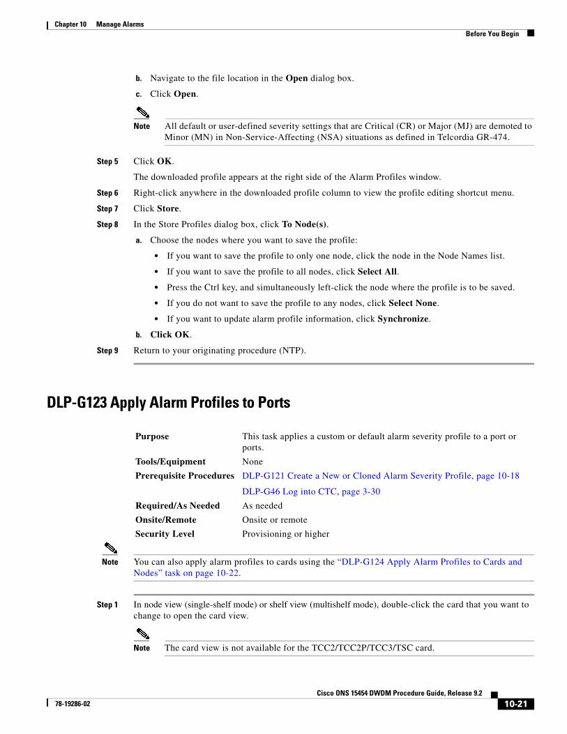
b. Navigate to the file location in the Open dialog box.
c. Click Open.
Note All default or user-defined severity settings that are Critical (CR) or Major (MJ) are demoted to Minor (MN) in Non-Service-Affecting (NSA) situations as defined in Telcordia GR-474-CORE.
Step 6 Click OK.
The alarm severity profile appears in the Alarm Profiles window. The alarm profile list contains a master list of alarms that is used for a mixed node network. Some of these alarms might not be used in all ONS nodes.
Step 7 Right-click anywhere in the profile column to view the profile editing shortcut menu. (Refer to Step 10 for further information about the Default profile.)
Step 8 Click Clone in the shortcut menu.
Tip To see the full list of profiles, including those available for loading or cloning, click Available. You must load a profile before you can clone it.
Purpose This task creates a custom severity profile or clones and modifies the default severity profile.
Tools/Equipment None
Prerequisite Procedures DLP-G46 Log into CTC, page 3-30
Required/As Needed As needed
Onsite/Remote Onsite or remote
Security Level Provisioning or higher
10-18Cisco ONS 15454 DWDM Procedure Guide, Release 9.2
78-19286-02
Chapter 10 Manage AlarmsBefore You Begin
Step 9 In the New Profile dialog box, enter a name in the New Profile Name field.
Profile names must be unique. If you try to import or name a profile that has the same name as another profile, CTC adds a suffix to create a new name. Long file names are supported.
Step 10 Click OK.
A new alarm profile (named in Step 9) is created. (If this is the first alarm profile created during installation, the default alarm profile settings are displayed in the AlarmType::Condition column on the left.) This profile duplicates the default profile severities and appears at the right of the previous profile column in the Alarm Profiles window. You can select it and drag it to a different position.
Note Up to ten profiles, including the two reserved profiles, Inherited and Default, can be stored in CTC.
The Default profile sets severities to standard Telcordia GR-474-CORE settings. If an alarm has an Inherited profile, it inherits (copies) its severity from the same alarm's severity at the higher level. For example, if you choose the Inherited profile from the network view, the severities at the lower levels (node, card, and port) will be copied from this selection. A card with an Inherited alarm profile copies the severities used by the node that contains the card. (If you are creating profiles, you can apply these separately at any level. To do this, refer to the “DLP-G124 Apply Alarm Profiles to Cards and Nodes” task on page 10-22.)
Step 11 Modify (customize) the new alarm profile:
a. In the new alarm profile column, click the alarm severity you want to change in the custom profile.
b. Choose a severity from the drop-down list.
c. Repeat Steps a and b for each severity you want to customize. Refer to the following guidelines when you view the alarms or conditions after making modifications:
• All Critical (CR) or Major (MJ) default or user-defined severity settings are demoted to Minor (MN) in Non-Service-Affecting (NSA) situations as defined in Telcordia GR-474-CORE.
• Default severities are used for all alarms and conditions until you create and apply a new profile.
• Changing a severity to inherited (I) or unset (U) does not change the severity of the alarm.
Step 12 After you have customized the new alarm profile, right-click the profile column to highlight it.
Step 13 Click Store.
Step 14 In the Store Profiles dialog box, click To Node(s) and go to Step a, or click To File and go to Step b.
a. Choose the node where you want to save the profile:
• If you want to save the profile to only one node, click the node in the Node Names list.
• If you want to save the profile to all nodes, click Select All.
• Press the Ctrl key, and simultaneously left-click the node where the profile is to be saved.
• If you do not want to save the profile to any nodes, click Select None.
• If you want to update alarm profile information, click (Synchronize).
• Click OK to save the profile.
b. Save the profile:
• Click Browse and navigate to the profile save location.
• Enter a name in the File name field.
10-19Cisco ONS 15454 DWDM Procedure Guide, Release 9.2
78-19286-02
Chapter 10 Manage AlarmsBefore You Begin
• Click Select to choose this name and location. Long file names are supported. CTC supplies a suffix of *.pfl to stored files.
• Click OK to store the profile.
Step 15 As needed, perform any of the following actions. The following options are located at the bottom of the Provisioning > Alarm Profile window.
• Click the Hide Identical Rows check box to configure the Alarm Profiles window to view rows with dissimilar severities.
• Click the Hide Reference Values check box to configure the Alarm Profiles window to view severities that do not match the Default profile.
• Click the Only show service-affecting severities check box to configure the Alarm Profiles window not to display Minor and some Major alarms that will not affect service.
Step 16 Return to your originating procedure (NTP).
DLP-G122 Download an Alarm Severity Profile
Note You must always store the alarm profile after editing it. If you edit an alarm profile without saving it, changes to the profile will be lost if you change views in CTC.
Step 1 To access the alarm profile editor from network view, click the Provisioning > Alarm Profiles tabs.
Note To access the profile editor from node view (single-shelf mode) or shelf view (multishelf mode), or card view, click the Provisioning > Alarm Profiles > Alarm Profile Editor tabs.
Step 2 Click Load.
Step 3 If you want to download a profile that exists on the node, click From Node in the Load Profiles dialog box.
a. Click the node name you are logged into in the Node Names list.
b. Click the name of the profile in the Profile Names list, such as Default.
c. Click OK.
Step 4 If you want to download a profile that is stored locally or on a network drive, click From File in the Load Profile dialog box.
a. Click Browse.
Purpose This task downloads a custom alarm severity profile from a network-drive-accessible CD-ROM, floppy disk, or hard disk location.
Tools/Equipment None
Prerequisite Procedures DLP-G46 Log into CTC, page 3-30
Required/As Needed As needed
Onsite/Remote Onsite or remote
Security Level Provisioning or higher
10-20Cisco ONS 15454 DWDM Procedure Guide, Release 9.2
78-19286-02
Chapter 10 Manage AlarmsBefore You Begin
b. Navigate to the file location in the Open dialog box.
c. Click Open.
Note All default or user-defined severity settings that are Critical (CR) or Major (MJ) are demoted to Minor (MN) in Non-Service-Affecting (NSA) situations as defined in Telcordia GR-474.
Step 5 Click OK.
The downloaded profile appears at the right side of the Alarm Profiles window.
Step 6 Right-click anywhere in the downloaded profile column to view the profile editing shortcut menu.
Step 7 Click Store.
Step 8 In the Store Profiles dialog box, click To Node(s).
a. Choose the nodes where you want to save the profile:
• If you want to save the profile to only one node, click the node in the Node Names list.
• If you want to save the profile to all nodes, click Select All.
• Press the Ctrl key, and simultaneously left-click the node where the profile is to be saved.
• If you do not want to save the profile to any nodes, click Select None.
• If you want to update alarm profile information, click Synchronize.
b. Click OK.
Step 9 Return to your originating procedure (NTP).
DLP-G123 Apply Alarm Profiles to Ports
Note You can also apply alarm profiles to cards using the “DLP-G124 Apply Alarm Profiles to Cards and Nodes” task on page 10-22.
Step 1 In node view (single-shelf mode) or shelf view (multishelf mode), double-click the card that you want to change to open the card view.
Note The card view is not available for the TCC2/TCC2P/TCC3/TSC card.
Purpose This task applies a custom or default alarm severity profile to a port or ports.
Tools/Equipment None
Prerequisite Procedures DLP-G121 Create a New or Cloned Alarm Severity Profile, page 10-18
DLP-G46 Log into CTC, page 3-30
Required/As Needed As needed
Onsite/Remote Onsite or remote
Security Level Provisioning or higher
10-21Cisco ONS 15454 DWDM Procedure Guide, Release 9.2
78-19286-02
Chapter 10 Manage AlarmsBefore You Begin
Step 2 Click the Provisioning > Alarm Profiles > Alarm Behavior tabs.
Go to Step 3 to apply profiles to a port. Go to Step 4 to apply profiles to all ports on a card.
Step 3 To apply profiles on a port basis:
a. In card view, click the port row in the Profile column.
b. Choose the new profile from the drop-down list.
c. Click Apply. Confirm the profile updated to the port correctly.
Step 4 To apply profiles to all ports on a card:
a. In card view, click the Force all ports to profile drop-down arrow at the bottom of the window.
b. Choose the new profile from the drop-down list.
c. Click Force (still need to “Apply”).
d. Click Apply. Confirm that the profile updated to all ports correctly.
In node view, the Port Level Profiles column indicates port-level profiles with a notation such as “exist (1)”.
Step 5 To reapply a previous alarm profile after you have applied a new one, select the previous profile and click Apply again.
Step 6 Return to your originating procedure (NTP).
DLP-G124 Apply Alarm Profiles to Cards and Nodes
Step 1 In node view (single-shelf mode) or shelf view (multishelf mode), click the Provisioning > Alarm Profiles > Alarm Behavior tab.
Step 2 To apply profiles to a card:
a. Click a selection from the Profile column for the card.
b. Choose the new profile from the drop-down list.
c. Click Apply.
Step 3 To apply the profile to an entire node:
a. Click the Force All Ports to Profile drop-down arrow at the bottom of the window.
b. Choose the new alarm profile from the drop-down list.
c. Click Force (still need to apply).
Step 4 Click Apply again.
Purpose This task applies a custom or default alarm profile to cards or nodes.
Tools/Equipment None
Prerequisite Procedures DLP-G121 Create a New or Cloned Alarm Severity Profile, page 10-18
DLP-G46 Log into CTC, page 3-30
Required/As Needed As needed
Onsite/Remote Onsite or remote
Security Level Provisioning or higher
10-22Cisco ONS 15454 DWDM Procedure Guide, Release 9.2
78-19286-02
Chapter 10 Manage AlarmsBefore You Begin
Step 5 Return to your originating procedure (NTP).
DLP-G125 Delete Alarm Severity Profiles
Step 1 To access the alarm profile editor from network view, click the Provisioning > Alarm Profiles > Alarm Profile Editor tabs.
Note To access the profile editor from node view (single-shelf mode) or shelf view (multishelf mode), or card view, click the Provisioning > Alarm Profiles > Alarm Profile Editor tabs.
Step 2 Click the Alarm Type::Condition column.
Step 3 Click Delete.
The Select Node/Profile Combination for Delete dialog box appears.
Note You cannot delete the Inherited or Default alarm profiles.
Note A previously created alarm profile cannot be deleted unless it has been stored on the node. If the profile is visible on the Alarm Profiles tab but is not listed in the Select Node/Profile Combinations to Delete dialog box, continue with Step 8.
Step 4 Click the node name in the Node Names list to highlight the profile location.
Tip If you hold the Shift key down, you can select consecutive node names. If you hold the Ctrl key down, you can select any combination of nodes.
Step 5 Click the profile names that you want to delete in the Profile Names list.
Step 6 Click OK.
Step 7 Click Yes in the Delete Alarm Profile dialog box.
If you delete a profile from a node, it still appears in the network view Provisioning > Alarm Profile Editor window unless you remove it using the following step.
Step 8 To remove the alarm profile from the window, right-click the column of the profile that you deleted and choose Remove from the shortcut menu.
Purpose This task deletes a custom or default alarm severity profile.
Tools/Equipment None
Prerequisite Procedures DLP-G46 Log into CTC, page 3-30
Required/As Needed As needed
Onsite/Remote Onsite or remote
Security Level Provisioning or higher
10-23Cisco ONS 15454 DWDM Procedure Guide, Release 9.2
78-19286-02
Chapter 10 Manage AlarmsBefore You Begin
If a node and profile combination is selected but does not exist, a warning appears: “One or more of the profiles selected do not exist on one or more of the node(s) selected.” For example, if Node A has only Profile 1 stored and the user tries to delete both Profile 1 and Profile 2 from Node A, this warning appears. However, the operation still removes Profile 1 from Node A.
The Default and Inherited special profiles cannot be deleted and do not appear in the Select Node/Profile Combination for Delete window.
Step 9 Return to your originating procedure (NTP).
NTP-G69 Enable, Modify, or Disable Alarm Severity Filtering
Step 1 Complete the “DLP-G46 Log into CTC” task on page 3-30 at the node where you want to enable alarm severity filtering. If you are already logged in, continue with Step 2.
Step 2 As needed, complete the “DLP-G126 Enable Alarm Filtering” task on page 10-25. This task enables alarm filtering at the card, shelf, node, and network views for all nodes in the network. Alarm filtering can be enabled for alarms, conditions, or events.
Step 3 As needed, complete the “DLP-G127 Modify Alarm, Condition, and History Filtering Parameters” task on page 10-25 to modify the alarm filtering for network nodes to show or hide particular alarms or conditions.
Step 4 As needed, complete the “DLP-G128 Disable Alarm Filtering” task on page 10-26 to disable alarm profile filtering for all network nodes.
Stop. You have completed this procedure.
Purpose Use this procedure to start, change, or stop alarm filtering for one or more severities in the Alarms, Conditions, and History windows in all network nodes.
Tools/Equipment None
Prerequisite Procedures Chapter 3, “Connect the PC and Log into the GUI”
Required/As Needed As needed
Onsite/Remote Onsite or remote
Security Level Retrieve or higher
10-24Cisco ONS 15454 DWDM Procedure Guide, Release 9.2
78-19286-02
Chapter 10 Manage AlarmsBefore You Begin
DLP-G126 Enable Alarm Filtering
Step 1 At the shelf, node, network, or card view, click the Alarms tab.
Step 2 Click the Filter tool icon on the right side of the bottom toolbar.
Note The Filter tool icon differs from the Filter button at the bottom left of the screen.
Alarm filtering is enabled in the card, node, and network views of the same window for all nodes in the network. For example, if the Filter tool is enabled in the node view Alarms window, the network view Alarms window and card view Alarms window also show the tool enabled.
Step 3 If you want alarm filtering enabled when you view conditions, click on the Conditions tab and repeat Steps 1 and 2.
Step 4 If you want alarm filtering enabled when you view alarm history, click on the Conditions tab and repeat Steps 1 and 2.
Step 5 Return to your originating procedure (NTP).
DLP-G127 Modify Alarm, Condition, and History Filtering Parameters
Step 1 At the shelf, node, network, or card view, click the Alarms tab, Conditions tab, or History tab.
Step 2 Click the Filter button on the left side of the bottom toolbar.
The filter dialog box appears, displaying the General tab.
Purpose This task enables alarm filtering for alarms, conditions, or event history in all network nodes.
Tools/Equipment None
Prerequisite Procedures DLP-G46 Log into CTC, page 3-30
Required/As Needed As neededOnsite/Remote Onsite or remoteSecurity Level Retrieve or higher
Purpose This task changes alarm and condition reporting in all network nodes.
Tools/Equipment None
Prerequisite Procedures DLP-G126 Enable Alarm Filtering, page 10-25
DLP-G46 Log into CTC, page 3-30
Required/As Needed As neededOnsite/Remote Onsite or remoteSecurity Level Retrieve or higher
10-25Cisco ONS 15454 DWDM Procedure Guide, Release 9.2
78-19286-02
Chapter 10 Manage AlarmsBefore You Begin
In the General tab Show Severity area, you can choose which alarm severities will show through the alarm filter and provision a time period during which filtered alarms show through the filter. To change the alarm severities shown in the filter, go to Step 3. To change the time period filter for the alarms, go to Step 4.
Step 3 In the Show Severity area, click the check boxes for the severities [Critical (CR), Major (MJ), Minor (MN), or Not Alarmed (NA)] that you want to be reported at the network level. Leave severity check boxes deselected (unchecked) to prevent those severities from appearing.
When alarm filtering is disabled, all alarms show.
Step 4 In the Time area, click the Show alarms between time limits check box to enable it. Click the up and down arrows in the From Date, To Date, and Time fields to modify the period of alarms that is shown.
To modify filter parameters for conditions, continue with Step 5. If you do not need to modify them, continue with Step 6.
Step 5 Click the filter dialog box Conditions tab.
When filtering is enabled, conditions in the Show list are visible and conditions in the Hide list are invisible.
• To move conditions individually from the Show list to the Hide list, click the > button.
• To move conditions individually from the Hide list to the Show list, click the < button.
• To move conditions collectively from the Show list to the Hide list, click the >> button.
• To move conditions collectively from the Hide list to the Show list, click the << button.
Note Conditions include alarms.
Step 6 Click Apply and OK.
Alarm and condition filtering parameters are enforced when alarm filtering is enabled (see the “DLP-G126 Enable Alarm Filtering” task on page 10-25), and the parameters are not enforced when alarm filtering is disabled (see the “DLP-G128 Disable Alarm Filtering” task on page 10-26).
Step 7 Return to your originating procedure (NTP).
DLP-G128 Disable Alarm Filtering
Step 1 At node, network, or card view, click the Alarms tab.
Purpose This task turns off specialized alarm filtering in all network nodes so that all severities are reported in CTC.
Tools/Equipment None
Prerequisite Procedures DLP-G126 Enable Alarm Filtering, page 10-25
DLP-G46 Log into CTC, page 3-30
Required/As Needed As neededOnsite/Remote Onsite or remoteSecurity Level Retrieve or higher
10-26Cisco ONS 15454 DWDM Procedure Guide, Release 9.2
78-19286-02
Chapter 10 Manage AlarmsBefore You Begin
Step 2 Alarm filtering is enabled if the tool is indented (the filter icon is blue) and disabled if the tool is raised (not selected; the filter icon is white). To disable alarm filtering, click the Filter tool icon on the right side of the bottom toolbar until it is raised (turns white).
Note The Filter tool icon differs from the Filter button at the bottom left of the screen.
Step 3 If you want alarm filtering disabled when you view conditions, click the Conditions tab and click the Filter tool.
Step 4 If you want alarm filtering disabled when you view alarm history, click the History tab and click the Filter tool.
Step 5 Return to your originating procedure (NTP).
NTP-G70 Suppress Alarms or Discontinue Alarm Suppression
Step 1 Complete the “DLP-G46 Log into CTC” task on page 3-30. If you are already logged in, continue with Step 2.
Step 2 Complete the “DLP-G129 Suppress Alarm Reporting” task on page 10-28 to enable the node to send autonomous messages that clear specific raised alarms and cause suppressed alarms to appear in the Conditions window.
Suppressing one or more alarms prevents them from appearing in the Alarm or History windows or in any other clients. The suppress command causes CTC to display them in the Conditions window with their severity, their severity color code, and their service-affecting status.
Step 3 Complete the “DLP-G130 Discontinue Alarm Suppression” task on page 10-29 to discontinue alarm suppression and resume normal alarm reporting.
Stop. You have completed this procedure.
Purpose Use this procedure to prevent alarms from being reported for a port, card, shelf, or node in circumstances when an alarm or condition is known to exist but you do not want to include it in the Alarms or History display. This procedure also provides a link to a task that explains how to resume normal alarm reporting by discontinuing the suppression.
Tools/Equipment None
Prerequisite Procedures Chapter 3, “Connect the PC and Log into the GUI”
Required/As Needed As needed
Onsite/Remote Onsite or remote
Security Level Provisioning or higher
10-27Cisco ONS 15454 DWDM Procedure Guide, Release 9.2
78-19286-02
Chapter 10 Manage AlarmsBefore You Begin
DLP-G129 Suppress Alarm Reporting
Caution If multiple CTC/TL1 sessions are open, suppressing alarms in one session suppresses the alarms in all other open sessions.
Note Alarm suppression at the node level does not supersede alarm suppression at the card or port level. Suppression can exist independently for all three entities, and each entity will raise separate alarms suppressed by the user command (AS-CMD) alarm.
Step 1 From the network view, right-click the node you want to suppress alarms and choose Open Node. From node view, click the Provisioning > Alarm Profiles > Alarm Behavior tabs.
Step 2 To suppress alarms for the entire node:
a. Check the Suppress Alarms check box.
b. Click Apply.
All raised alarms for the node will change color to white in the Alarms window and their status will change to cleared. After suppressing alarms, clicking Synchronize in the Alarms window will remove cleared alarms from the window. However, an AS-CMD alarm will show in node or card view to indicate that node-level alarms were suppressed, and the word System will appear in the Object column.
Note The only way to suppress building integrated timing supply (BITS), power source, or system alarms is to suppress alarms for all the non-card objects.
Step 3 To suppress alarms for individual cards, go to the shelf view and click the Provisioning > Alarm Profiles > Alarm Behavior tabs:
a. In the alarm behavior window, locate the card row (using the Location column for the slot number or the Eqpt Type column for the equipment name).
b. Check the Suppress Alarms column check box in that row.
Alarms that directly apply to this card will change appearance as described in Step 2. For example, if you suppressed raised alarms for an TXP_MR_10G card in Shelf 2, Slot 16, raised alarms for this card will change in node or card view. The AS-CMD alarm will show the slot number in the Object number. For example, if you suppressed alarms for a Slot 16 TXP_MR_10G card, the AS-CMD object will be “SLOT-2-16.”
c. Click Apply.
Purpose This task suppresses the reporting of ONS 15454 alarms at the node, shelf, card, or port level.
Tools/Equipment None
Prerequisite Procedures DLP-G46 Log into CTC, page 3-30
Required/As Needed As needed
Onsite/Remote Onsite or remote
Security Level Provisioning or higher
10-28Cisco ONS 15454 DWDM Procedure Guide, Release 9.2
78-19286-02
Chapter 10 Manage AlarmsBefore You Begin
Step 4 To suppress alarms for ECU multishelf ports, go to the shelf view and click the Provisioning > Alarm Profiles > ECU Multishelf Ports Alarm Suppression tabs:
a. In the ECU multishelf ports alarm suppression window, check the Suppress Alarms column check box for the port where you want to suppress alarms.
b. Click Apply.
Alarms that apply directly to this port will change appearance as described in Step 2.
Step 5 To suppress alarms for individual card ports, double-click the card in node view.
a. Click the Provisioning > Alarm Profiles > Alarm Behavior tabs.
b. Check the Suppress Alarms column check box for the port row where you want to suppress alarms.
c. Click Apply.
Alarms that apply directly to this port will change appearance as described in Step 2. (However, alarms raised on the entire card will remain raised.) A raised AS-CMD alarm that shows the port as its object will appear in either alarm window. For example, if you suppressed alarms for Port 1 on the Slot 16 OC-48 card, the alarm object will show “FAC-16-1.”
Step 6 Return to your originating procedure (NTP).
DLP-G130 Discontinue Alarm Suppression
Caution If multiple CTC sessions are open, discontinuing suppression in one session will discontinue suppression in all other open sessions.
Step 1 To discontinue alarm suppression for the entire node:
a. In node view, click the Provisioning > Alarm Profiles > Alarm Behavior tab.
b. Uncheck the Suppress Alarms check box.
Suppressed alarms will reappear in the Alarms window. (They might have previously been cleared from the window using the Synchronize button.) The AS-CMD alarm with the System object will be cleared in all views.
Step 2 To discontinue alarm suppression for individual cards:
a. In node view, click the Provisioning > Alarm Profiles > Alarm Behavior tabs.
b. Locate the card that is suppressed in the slot list.
Purpose This task discontinues alarm suppression and reenables alarm reporting on a port, card, shelf, or node.
Tools/Equipment None
Prerequisite Procedures DLP-G129 Suppress Alarm Reporting, page 10-28
DLP-G46 Log into CTC, page 3-30
Required/As Needed As needed
Onsite/Remote Onsite or remote
Security Level Provisioning or higher
10-29Cisco ONS 15454 DWDM Procedure Guide, Release 9.2
78-19286-02
Chapter 10 Manage AlarmsBefore You Begin
c. Uncheck the Suppress Alarms column check box for that slot.
d. Click Apply.
Suppressed alarms will reappear in the Alarms window. (They might have previously been cleared from the window using the Synchronize button.) The AS-CMD alarm with the slot object (for example, SLOT-16) will be cleared in all views.
Step 3 To discontinue alarm suppression for ECU ports, from the shelf view click the Provisioning > Alarm Profiles > ECU Multishelf Ports Alarm Suppression tabs:
a. Uncheck the Suppress Alarms check box for the port(s) that you no longer want to suppress.
b. Click Apply.
Step 4 To discontinue alarm suppression for card ports, from the card view click the Provisioning > Alarm Profiles > Alarm Behavior tabs.
a. Uncheck the Suppress Alarms check box for the port(s) that you no longer want to suppress.
b. Click Apply.
Suppressed alarms will reappear in the Alarms window. (They might have previously been cleared from the window using the Synchronize button.) The AS-CMD alarm with the port object (for example, FAC-16-1) will be cleared in all views.
Step 5 Return to your originating procedure (NTP).
NTP-G72 Provision External Alarms and Controls on the Alarm Interface Controller-International Card
Note On the ONS 15454 ANSI shelf, the AIC-I card alarm provides direct alarm contacts (external alarm inputs and external control outputs) routed through the backplane to wire-wrap pins accessible from the back of the shelf. If you install an Alarm Expansion Panel (AEP), the AIC-I alarm contacts cannot be used. Only the AEP alarm contacts can be used. For further information about the AEP, see “NTP-G9 Install the Alarm Expansion Panel (ANSI Only)” and the “NTP-G11 Install an External Wire-Wrap Panel on the AEP (ANSI Only)” in the Cisco ONS 15454 Hardware Installation Guide. The ONS 15454 ETSI shelf is not compatible with the AEP.
Note For information about the AIC-I external alarms, external controls, and virtual wire, refer to the “Alarm and TCA Monitoring and Management” chapter in the Cisco ONS 15454 DWDM Reference Manual.
Purpose Use this procedure to create external (environmental) alarms and external controls for the AIC-I card.
Tools/Equipment An AIC-I card must be installed in Slot 9.
Prerequisite Procedures “DLP-G34 Install the AIC-I Card” in the Cisco ONS 15454 Hardware Installation Guide
Required/As Needed As needed
Onsite/Remote Onsite or remote
Security Level Provisioning or higher
10-30Cisco ONS 15454 DWDM Procedure Guide, Release 9.2
78-19286-02
Chapter 10 Manage AlarmsBefore You Begin
Step 1 If you are using an ONS 15454 ANSI shelf, verify the backplane wiring. If you are using the AEP, see the “NTP-G9 Install the Alarm Expansion Panel (ANSI Only)” in the Cisco ONS 15454 Hardware Installation Guide. Otherwise, see the “NTP-G10 Attach Wires to Alarm, Timing, LAN, and Craft Pin Connections” in the Cisco ONS 15454 Hardware Installation Guide for information about the ONS 15454 backplane pins.
a. For external alarms, verify that the external device relays are wired to the ENVIR ALARMS IN backplane pins.
b. For external controls, verify that the external device relays are wired to the ENVIR ALARMS OUT backplane pins.
Step 2 If you are using an ONS 15454 ETSI shelf, verify the alarm contact wiring. See the “NTP-G10 Attach Wires to Alarm, Timing, LAN, and Craft Pin Connections” in the Cisco ONS 15454 Hardware Installation Guide for information about the ONS 15454 SDH contacts.
a. For external alarms, verify that the external device relays are wired to the ENVIR ALARMS IN connector pins.
b. For external controls, verify the external device relays are wired to the ENVIR ALARMS OUT connector pins.
Step 3 Complete the “DLP-G46 Log into CTC” task on page 3-30. If you are already logged in, continue with Step 4.
Step 4 In node or shelf view, double-click the AIC-I card on the shelf graphic. The card view appears.
Step 5 Click the Provisioning > Card tabs.
Step 6 In the Alarm Contacts area, click the Add Extension radio button if you are using the AEP. Clicking this option will choose the External Alarm input/output type and the AEP extension type; it will give you access to 16 external alarm contacts.
Step 7 If you did not click Add Extension, in the Input/Output area choose either External Alarm or External Control. (External Alarm will limit your input/output options as explained in Step 6.) Choosing External Control will enable both external alarms and external controls. This will convert four of the external alarm contacts to external controls, leaving 12 available external control contacts. The extension type for both options is AEP.
Step 8 If you are provisioning external alarms, click the External Alarms tab. If you are not provisioning external alarms, skip Steps 9 through 11 and go to Step 12.
Step 9 For external alarms, complete the following fields:
• Enabled—Check the check box to activate the fields for the alarm input number.
• Alarm Type—Choose an alarm type from the drop-down list.
• Severity—Choose a severity from the drop-down list.
The severity determines the alarm’s severity in the Alarms and History tabs and determines whether the LEDs are activated. Critical (CR), Major (MJ), and Minor (MN) alarms activate the LEDs. Not Alarmed (NA) and Not Reported (NR) events do not activate LEDs, but do report the information in CTC.
• Virtual Wire—Choose the virtual wire number from the drop-down list if you want to assign the external device to a virtual wire. Otherwise, do not change the None default.
• Raised When—From the drop-down list, choose the contact condition (open or closed) that triggers the alarm.
• Description—A default description is provided; enter a different description if needed. (Double-click the cell and highlight the text to change it.)
10-31Cisco ONS 15454 DWDM Procedure Guide, Release 9.2
78-19286-02
Chapter 10 Manage AlarmsBefore You Begin
Step 10 To provision additional devices, complete Step 9 for each additional device.
Step 11 Click Apply.
When you provision an external alarm, the alarm object is ENV-IN-nn. The variable nn refers to the external alarm’s number, regardless of the name you assign.
Step 12 For external controls, click the External Controls tab and complete the following fields for each control wired to the ONS 15454 backplane (ANSI) or FMEC connector pins (ETSI):
• Enabled—Check this check box to activate the fields for the alarm input number.
• Control Type—Choose the control type from the drop-down list: air conditioner, engine, fan, generator, heat, light, sprinkler, or miscellaneous.
• Trigger Type—Choose a trigger type: a local minor, major, or critical alarm; a remote minor, major, or critical alarm; or a virtual wire activation.
• Description—Enter a description. (Double-click on the cell and highlight the text to change it.)
Step 13 To provision additional external controls, complete Step 12 for each device.
Step 14 Click Apply.
Note External alarms and controls should be recorded locally for the network element (NE). Both the alarm name and resolution are node-specific.
Stop. You have completed this procedure.
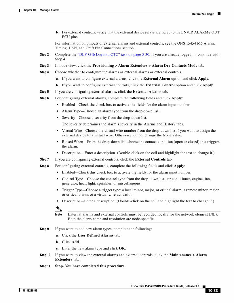
NTP-G277 Provision Alarms and Controls on the TNC or TSC Card
Note For information about external alarms and external controls, refer to the “Alarm and TCA Monitoring and Management” chapter in the Cisco ONS 15454 DWDM Reference Manual.
Note You can configure up to 14 alarm input ports in the external alarms mode. You can configure up to 10 alarm input ports and four alarm output ports in the external control mode.
Step 1 Verify the ECU connections.
a. For external alarms, verify that the external device relays are wired to the ENVIR ALARMS IN ECU pins.
Purpose Use this procedure to configure and view external (environmental) alarms and external controls for the TNC or TSC card on the 15454-M6 shelf.
Tools/Equipment The TNC/TSC cards must be installed in Slot 1 or 8.
Prerequisite Procedures “DLP-G604 Install the TNC or TSC Card” in the Cisco ONS 15454 Hardware Installation Guide
Required/As Needed As needed
Onsite/Remote Onsite or remote
Security Level Provisioning or higher
10-32Cisco ONS 15454 DWDM Procedure Guide, Release 9.2
78-19286-02
Chapter 10 Manage AlarmsBefore You Begin
b. For external controls, verify that the external device relays are wired to the ENVIR ALARMS OUT ECU pins.
For information on pinouts of external alarms and external controls, see the ONS 15454 M6 Alarm, Timing, LAN, and Craft Pin Connections section.
Step 2 Complete the “DLP-G46 Log into CTC” task on page 3-30. If you are already logged in, continue with Step 4.
Step 3 In node view, click the Provisioning > Alarm Extenders > Alarm Dry Contacts Mode tab.
Step 4 Choose whether to configure the alarms as external alarms or external controls.
a. If you want to configure external alarms, click the External Alarm option and click Apply.
b. If you want to configure external controls, click the External Control option and click Apply.
Step 5 If you are configuring external alarms, click the External Alarms tab.
Step 6 For configuring external alarms, complete the following fields and click Apply:
• Enabled—Check the check box to activate the fields for the alarm input number.
• Alarm Type—Choose an alarm type from the drop-down list.
• Severity—Choose a severity from the drop-down list.
The severity determines the alarm’s severity in the Alarms and History tabs.
• Virtual Wire—Choose the virtual wire number from the drop-down list if you want to assign the external device to a virtual wire. Otherwise, do not change the None value.
• Raised When—From the drop-down list, choose the contact condition (open or closed) that triggers the alarm.
• Description—Enter a description. (Double-click on the cell and highlight the text to change it.)
Step 7 If you are configuring external controls, click the External Controls tab.
Step 8 For configuring external controls, complete the following fields and click Apply:
• Enabled—Check this check box to activate the fields for the alarm input number.
• Control Type—Choose the control type from the drop-down list: air conditioner, engine, fan, generator, heat, light, sprinkler, or miscellaneous.
• Trigger Type—Choose a trigger type: a local minor, major, or critical alarm; a remote minor, major, or critical alarm; or a virtual wire activation.
• Description—Enter a description. (Double-click on the cell and highlight the text to change it.)
Note External alarms and external controls must be recorded locally for the network element (NE). Both the alarm name and resolution are node-specific.
Step 9 If you want to add new alarm types, complete the following:
a. Click the User Defined Alarms tab.
b. Click Add
c. Enter the new alarm type and click OK.
Step 10 If you want to view the external alarms and external controls, click the Maintenance > Alarm Extenders tab.
Step 11 Stop. You have completed this procedure.
10-33Cisco ONS 15454 DWDM Procedure Guide, Release 9.2
78-19286-02

Chapter 10 Manage AlarmsBefore You Begin
10-34Cisco ONS 15454 DWDM Procedure Guide, Release 9.2
78-19286-02


![Car Alarms & Smoke Alarms [Monitorama]](https://img.pdfslide.net/doc/110x75/54b6cdf94a7959d84d8b45a5/car-alarms-smoke-alarms-monitorama.jpg)