Embed Size (px)
Citation preview
C H A P T E R
11
Security in Smart Cyber-PhysicalSystems: A Case Study on Smart Grids
and Smart CarsSandeep Nair Narayanan*, Kush Khanna†, Bijaya Ketan Panigrahi†,
and Anupam Joshi**University of Maryland Baltimore County, Baltimore, MD, United States
†Indian Institute of Technology Delhi, New Delhi, India
1 INTRODUCTION
Across the globe, cities are expanding in size and infrastructure. The idea of Smart Cities plays a vital role in offeringhigher efficiency, comfort, awareness, and convenience to end users. Harrison et al. [1] describe the Smart City as aninstrumented, interconnected, and intelligent city. They instrument different sectors of smart infrastructure, such assmart energy, smart transportation, smart governance, smart healthcare, smart buildings, and so forth to capture real-world data and interconnect them to share this data among different services. The shared data is then used to makeintelligent operational decisions using complex analytics and provide better facilities to end users. Smart Cyber-Physical Systems (CPSs) are essential components of all smart infrastructure. According to the National ScienceFoundation (NSF),1 “Cyber-physical systems integrate sensing, computation, control and networking into physicalobjects and infrastructure, connecting them to the Internet and each other.” Smart cars and smart grids are twoCPS domains that have demonstrated tremendous growth over the past few decades. However, the capabilities ofthese CPSs to influence critical infrastructure make them a lucrative target for hackers. Some of the attacks even havea direct impact on the economy of a nation. For example, consider the attack on the Ukrainian smart grids [2]. It left awhole city without heat and electricity in the cold of December for many hours. Similarly in the domain of smart cars,although they are capable of providing efficient transportation and fewer accidents, the potential attacks against themare alarming. The famous Jeep Hack of 2016, in which the researchers manipulated a moving unaltered vehicle on theroad, resulted in Chrysler recalling 1.4 million2 vehicles. Hence, there is an urgent requirement to secure these indi-vidual Smart City components. In this chapter, we delve into the general architecture and security of smart grids andsmart cars.
Electrical energy is considered the most efficient form of energy for generation, transmission, and energy conver-sion. The traditional power grid is getting smarter with large-scale automation and integration of new smart compo-nents capable of quick decision making, thereby improving the reliability of the entire system. The futuristic “smartgrid” is a cyber-physical power system of interconnected smart metering infrastructure that enables autonomous andresilient operation. Due to technological advances, many consumer-centric facilities such as demand-side manage-ment, advanced metering infrastructure, dynamic pricing, and incentives have evolved for serving the consumerin a better and more reliable way. The huge amount of data collected from smart meters across the cities will resultin better management of resources, ultimately lowering the cost for consumers.
1 See https://www.nsf.gov/news/special_reports/cyber-physical/.2 See https://www.wired.com/2015/07/jeep-hack-chrysler-recalls-1-4m-vehicles-bug-fix/.
147Smart Cities Cybersecurity and Privacy
https://doi.org/10.1016/B978-0-12-815032-0.00011-1
© 2019 Elsevier Inc. All rights reserved.
148 11. SECURITY IN SMART CYBER-PHYSICAL SYSTEMS: A CASE STUDY ON SMART GRIDS AND SMART CARS
Another CPS that acquired smart decision-making capability is cars. They developed from being just mechanicaldevices into machines that can drive autonomously. They can provide safe, efficient, and fast transportation inSmart Cities. Driver-assisted features, such as antilock braking systems (ABS), adaptive cruise control, and blind spotwarning systems, are becoming the de facto in many newer cars. For example, the latest version of the Accord fromHonda Motor Company has the Honda Sensing3 (Honda’s package of smart features such as the Collision MitigationBraking System, Road Departure Mitigation System, Adaptive Cruise Control, and Lane Keeping Assist System)feature as a default, even for its base version. Current cutting-edge research in this domain focuses on autonomousdriving in which a car can navigate you from one location to another without direct human intervention. Waymo4
(an Alphabet company), Uber,5 GM motors,6 Tesla,7 and so forth are some the automotive giants who are innovatingin this area. Waymo’s fleet of autonomous cars has already driven more than 4 million8 combined miles onnormal roads.
When the smart features of CPSs were upgraded, they were connected to the cloud environment over the Internet,either directly or indirectly. The lack of connectivity was acting as a security feature in disguise until it became defunct.Moreover, power grids and automobiles existed for a long period, and evolved over the past century. The designconsiderations for some of the legacy systems were efficiency and speed with lower priority to security features suchas authentication and authorization. For example, the Controller Area Network (CAN) bus used in many cars is asimple broadcast bus and messages on it are considered authenticated. An attacker who can sneak a crafted messageon this bus can perform many malicious activities. Supporting such legacy devices makes their security complicatedand opens many interesting research avenues.
This chapter explores the general architecture of smart grids and smart cars as smart CPSs in Section 2. Sections 3and 4 then delve into the security in smart grids and smart cars by discussing specific attacks and countermeasuresproposed to identify those attacks. Finally, this chapter is concluded in Section 5 by presenting the future outlook onthe cybersecurity issues in smart systems, and discussing recommendations.
2 GENERAL SMART CYBER-PHYSICAL SYSTEM ARCHITECTURE
As described in Section 1, smart CPSs are essential components of a Smart City. Each system should be instrumen-ted and interconnected to build it. In this section, we describe the architecture of two such instrumented smartCPSs, smart grids (Section 2.1) and smart cars (Section 2.2).
2.1 Smart Cyber-Physical System: Smart Grids
The union of Information Technology (IT) and Operational Technology (OT) has resulted in higher reliability, effi-ciency, better services, and ease of use for customers and utilities in every domain. In the recent past, the electricalenergy sector is witnessing extensive modernization owing to the convergence of cyber and physical technologies.The main objective of the power system is to generate and transmit electrical energy from the power plants to the con-sumers reliably and efficiently. A cyber-physical power system can be considered a conventional power grid with inte-grated communication technologies enabling cyber and physical connections between various power systemcomponents. An overview of the electrical power system with a review of state-of-the-art communication technologyis presented in later sections.
2.1.1 Electric Power system
The conventional power system can be broadly divided into three core domains: generation, transmission, anddistribution. The generating units (power plants) are generally located in remote areas far from the end consumers.To transmit electrical power efficiently, the voltage level at the generation site is stepped up using power trans-formers. The generation site is also equipped with generation remote terminal units (RTUs), integrated electronic
3 See https://automobiles.honda.com/safety.4 See https://waymo.com/.5 See https://www.uber.com/.6 See https://www.gm.com/.7 See https://www.tesla.com/.8 See https://waymo.com/ontheroad/.
1492 GENERAL SMART CYBER-PHYSICAL SYSTEM ARCHITECTURE
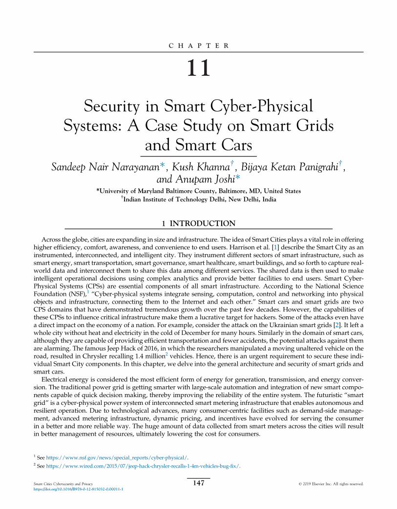
devices (IEDs), current and voltage transformers (CTs/PTs), relays, and circuit breakers (CBs) for protection andcontrol of critical generating units. The transmission system transmits high-voltage electrical power to the distribu-tion system, which further distributes electrical energy to the consumers (industries, commercial buildings, hospi-tals, and households) as shown in Fig. 1. The transmission system is equipped with phasor measurement units(PMUs), RTUs, and IEDs to measure voltage and current for the operation, and to monitor power systems. Inthe smart grid environment, the measured data from various RTUs, PMUs, and IEDs are received by data concen-trating units installed at the substations, and are further transmitted to a control center. The operation of conven-tional power systemswith the integration of communication technology ismore transparent as the latter has enabledwide area situational awareness of power system components available at the control center.
2.1.1.1 Power System Operation and Control
Supervisory control and data acquisition (SCADA) systems receive metered data for monitoring the operation ofa power system. Based on the measurements received from the SCADA system, a state estimator (SE) is used to obtainan accurate snapshot of the power system in real-time [3]. Power system stability and security studies rely heavily onthe estimated states. To ensure the accuracy of the estimated states, an SE generally uses redundant measurementsthat will filter out noises and telemetry errors [4]. Estimation of voltages at each bus (node) of the power systemis the prime objective of an SE. The measurements required for the correct estimation of V∠θ (complex voltage) ateach bus are real and reactive power injections at buses; real and reactive power flows in the transmission lines;and voltage measurements at generator buses.
For N bus power system, the total number of states to be estimated is 2N � 1; that is, N � 1 angles (one angle isconsidered as the reference angle) and N voltage magnitudes.
The state vector is given as,
x¼ ½θ2,θ3,…,θN ,V1,V2,…,VN�: (1)
Transmission andsubtransmission
Generation
Relay IED
Control center
Historicaldatabase
Wide areacommunication network
Smart meters/AMI collector
Industries andDERs
Distribution
FIG. 1 Complete smart grid schematic.
150 11. SECURITY IN SMART CYBER-PHYSICAL SYSTEMS: A CASE STUDY ON SMART GRIDS AND SMART CARS
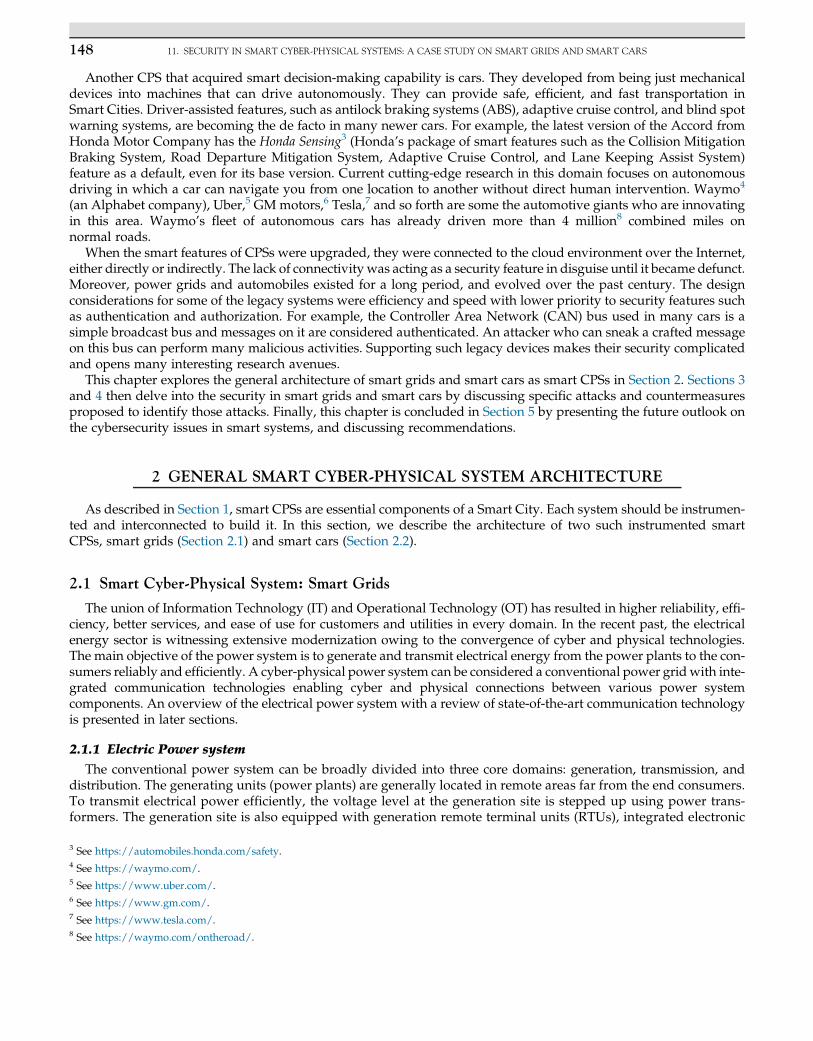
Once the power system states are estimated, the security and contingency analysis is carried out for the power system’sestimated snapshot. The EMS is responsible for unit commitment, economic load dispatch, automatic generation con-trol, and many other critical functions of the power grid. Fig. 2 highlights the importance of SE in the operation andcontrol of power systems.
2.1.1.2 Communication Technology
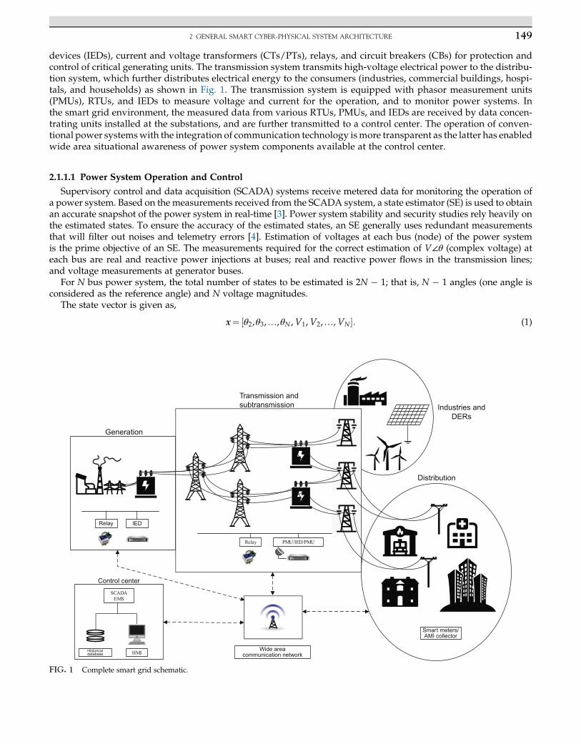
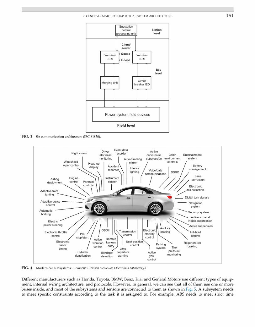
To transfer information from RTUs, IEDs, and relays to substations; from substations to regional and central loaddispatch centers; from market operators to independent system operators (ISOs); and in a smart grid environment,from end consumers to utilities and vice versa, the smart cyber-physical power system uses varied communicationtechnologies. Dedicated cables, optical fiber communication, wireless communication, and power line carriers aresome of the communication technologies used in the smart grid. For substation automation (SA), the IEC 61850 Stan-dard enhances the interoperability of devices from different vendors. In addition, IEC 61850 supports high-speed com-munication of generic object oriented substation event (GOOSE) messages for sending trip commands from relays toCBs, as shown in Fig. 3. IEC 61850 also supports sampled values to sendmeasured voltage and current values from themeasurement devices to the merger units. Manufacturing message specification is used to communicate device statusand control commands to and from IEDs.
Deployment of PMUs increases the situational awareness of large-scale power systems. PMUs are capable of sam-pling data at 60–240 Hz. The sampled data is time stamped and synchronized using global positioning systems (GPS).The data from the PMU is transmitted to the phasor data concentrator (PDC) using a standard IEEE C37.118 protocol.PDC further communicates over the Ethernet and local area network of the substation or control center to theSA/SCADA/EMS system. PMUs facilitate voltage and current measurements with a common reference (as data istime stamped), which results in accurate state estimation (SE) and enhances the observability of the power system.
2.2 Smart Cyber-Physical System: Smart Cars
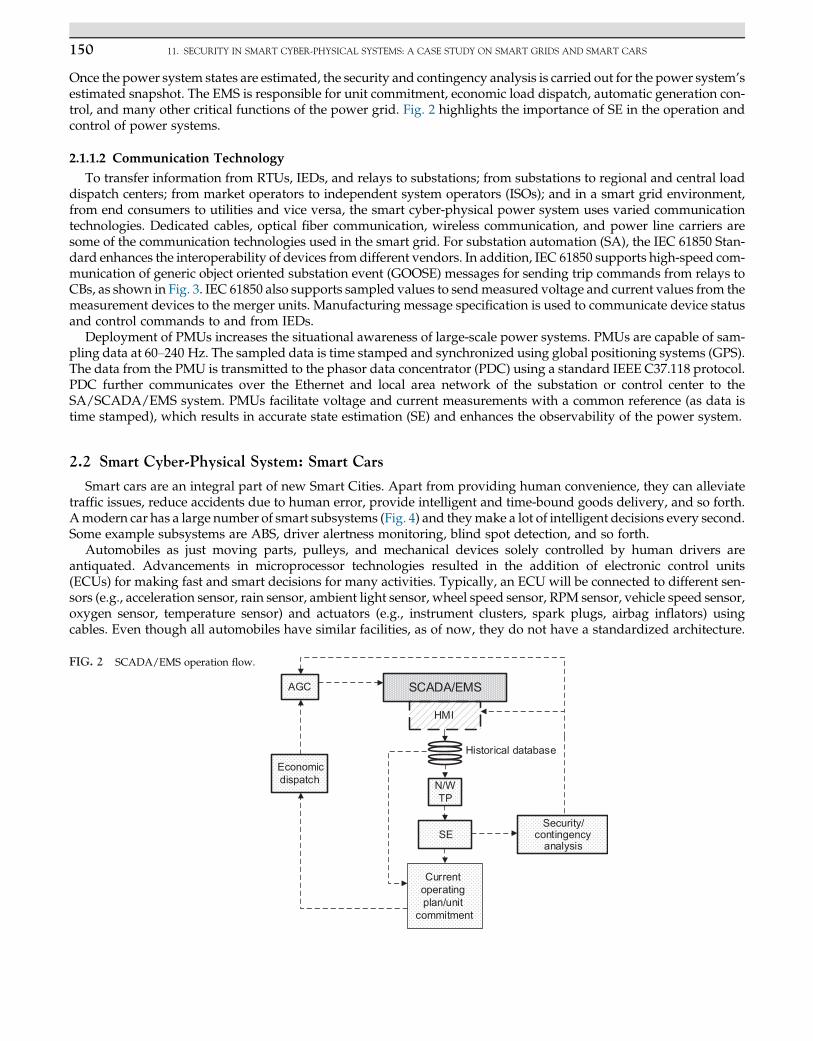
Smart cars are an integral part of new Smart Cities. Apart from providing human convenience, they can alleviatetraffic issues, reduce accidents due to human error, provide intelligent and time-bound goods delivery, and so forth.Amodern car has a large number of smart subsystems (Fig. 4) and theymake a lot of intelligent decisions every second.Some example subsystems are ABS, driver alertness monitoring, blind spot detection, and so forth.
Automobiles as just moving parts, pulleys, and mechanical devices solely controlled by human drivers areantiquated. Advancements in microprocessor technologies resulted in the addition of electronic control units(ECUs) for making fast and smart decisions for many activities. Typically, an ECU will be connected to different sen-sors (e.g., acceleration sensor, rain sensor, ambient light sensor, wheel speed sensor, RPM sensor, vehicle speed sensor,oxygen sensor, temperature sensor) and actuators (e.g., instrument clusters, spark plugs, airbag inflators) usingcables. Even though all automobiles have similar facilities, as of now, they do not have a standardized architecture.
SCADA/EMS
N/WTP
Security/contingency
analysis
AGC
HMI
Historical database
Current operating plan/unit
commitment
SE
Economic dispatch
FIG. 2 SCADA/EMS operation flow.
Driveralertnessmonitoring
Event datarecorder
Auto-dimmingmirror
Activecabin noisesuppression
Cabinenvironment
controls
Entertainmentsystem
Batterymanagement
Lanecorrection
Electronictoll collection
Digital turn signals
Navigationsystem
Security system
Active exhaustNoise suppression
Active suspension
Hill-holdcontrol
RegenerativebrakingTire
pressuremonitoring
Parkingsystem
Activeyaw
control
AntilockbrakingElectronic
stabilitycontrol
Transmissioncontrol
Seat positioncontrol
Lanedeparturewarning
Blindspotdetection
Remotekeylessentry
Activevibrationcontrol
OBDII
Cylinderdeactivation
Idlestop/start
Electronicvalvetiming
Electronic throttlecontrol
Electricpower steering
Automaticbraking
Adaptive cruisecontrol
Adaptive frontlighting
Airbagdeployment
Enginecontrol Parental
controls
Instrumentcluster
Night vision
Windshieldwiper control
Head-updisplay Accident
recorder Interiorlighting Voice/data
communications DSRC
FIG. 4 Modern car subsystems. (Courtesy: Clemson Vehicular Electronics Laboratory.)
Substationcentral
processing unitStation
level
Client/server
Baylevel
Merging unitCircuit
breaker IED
Power system field devices
Field level
Goose
Goose
FIG. 3 SA communication architecture (IEC 61850).
1512 GENERAL SMART CYBER-PHYSICAL SYSTEM ARCHITECTURE
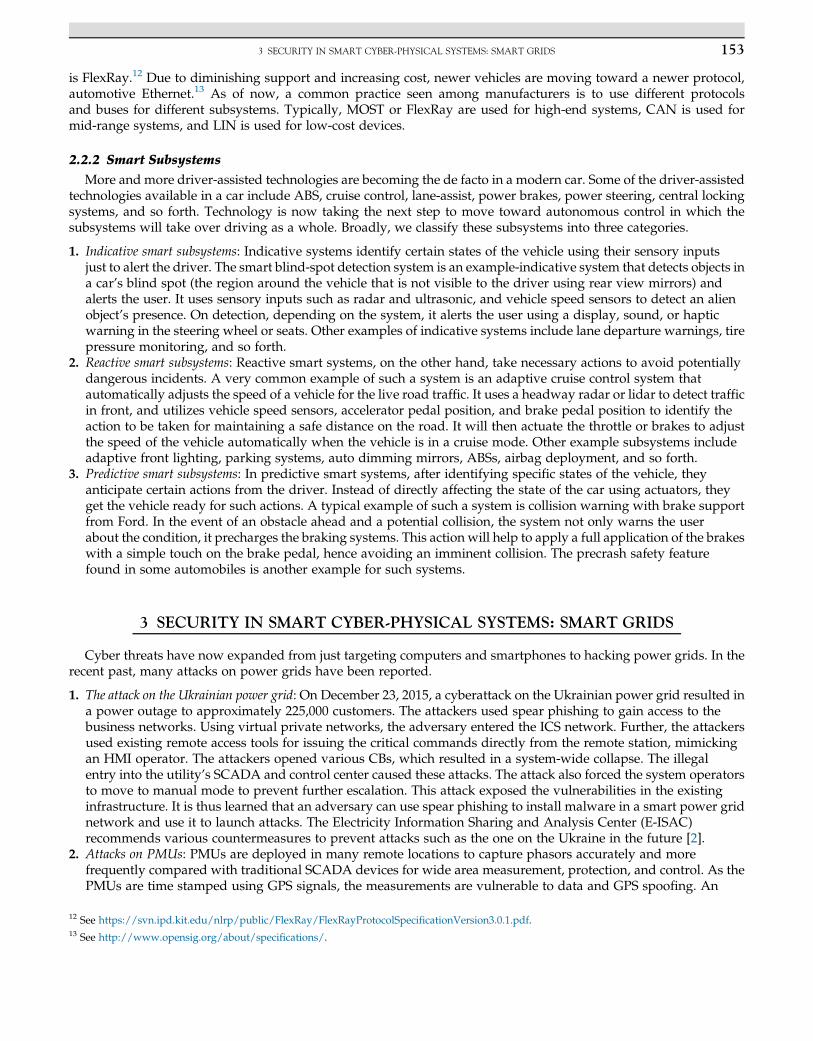
Different manufacturers such as Honda, Toyota, BMW, Benz, Kia, and General Motors use different types of equip-ment, internal wiring architecture, and protocols. However, in general, we can see that all of them use one or morebuses inside, and most of the subsystems and sensors are connected to them as shown in Fig. 5. A subsystem needsto meet specific constraints according to the task it is assigned to. For example, ABS needs to meet strict time
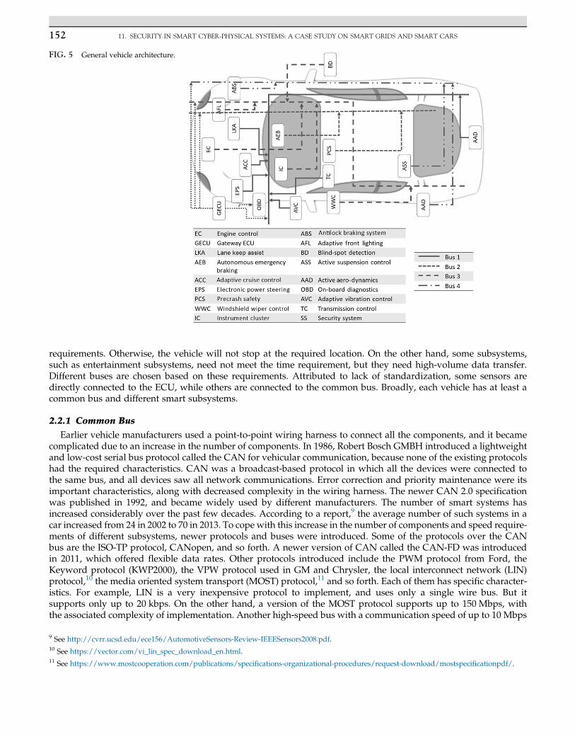
FIG. 5 General vehicle architecture.
152 11. SECURITY IN SMART CYBER-PHYSICAL SYSTEMS: A CASE STUDY ON SMART GRIDS AND SMART CARS
requirements. Otherwise, the vehicle will not stop at the required location. On the other hand, some subsystems,such as entertainment subsystems, need not meet the time requirement, but they need high-volume data transfer.Different buses are chosen based on these requirements. Attributed to lack of standardization, some sensors aredirectly connected to the ECU, while others are connected to the common bus. Broadly, each vehicle has at least acommon bus and different smart subsystems.
2.2.1 Common Bus
Earlier vehicle manufacturers used a point-to-point wiring harness to connect all the components, and it becamecomplicated due to an increase in the number of components. In 1986, Robert Bosch GMBH introduced a lightweightand low-cost serial bus protocol called the CAN for vehicular communication, because none of the existing protocolshad the required characteristics. CAN was a broadcast-based protocol in which all the devices were connected tothe same bus, and all devices saw all network communications. Error correction and priority maintenance were itsimportant characteristics, along with decreased complexity in the wiring harness. The newer CAN 2.0 specificationwas published in 1992, and became widely used by different manufacturers. The number of smart systems hasincreased considerably over the past few decades. According to a report,9 the average number of such systems in acar increased from 24 in 2002 to 70 in 2013. To cope with this increase in the number of components and speed require-ments of different subsystems, newer protocols and buses were introduced. Some of the protocols over the CANbus are the ISO-TP protocol, CANopen, and so forth. A newer version of CAN called the CAN-FD was introducedin 2011, which offered flexible data rates. Other protocols introduced include the PWM protocol from Ford, theKeyword protocol (KWP2000), the VPW protocol used in GM and Chrysler, the local interconnect network (LIN)protocol,10 the media oriented system transport (MOST) protocol,11 and so forth. Each of them has specific character-istics. For example, LIN is a very inexpensive protocol to implement, and uses only a single wire bus. But itsupports only up to 20 kbps. On the other hand, a version of the MOST protocol supports up to 150 Mbps, withthe associated complexity of implementation. Another high-speed bus with a communication speed of up to 10 Mbps
9 See http://cvrr.ucsd.edu/ece156/AutomotiveSensors-Review-IEEESensors2008.pdf.10 See https://vector.com/vi_lin_spec_download_en.html.11 See https://www.mostcooperation.com/publications/specifications-organizational-procedures/request-download/mostspecificationpdf/.
1533 SECURITY IN SMART CYBER-PHYSICAL SYSTEMS: SMART GRIDS
is FlexRay.12 Due to diminishing support and increasing cost, newer vehicles are moving toward a newer protocol,automotive Ethernet.13 As of now, a common practice seen among manufacturers is to use different protocolsand buses for different subsystems. Typically, MOST or FlexRay are used for high-end systems, CAN is used formid-range systems, and LIN is used for low-cost devices.
2.2.2 Smart Subsystems
More and more driver-assisted technologies are becoming the de facto in a modern car. Some of the driver-assistedtechnologies available in a car include ABS, cruise control, lane-assist, power brakes, power steering, central lockingsystems, and so forth. Technology is now taking the next step to move toward autonomous control in which thesubsystems will take over driving as a whole. Broadly, we classify these subsystems into three categories.
1. Indicative smart subsystems: Indicative systems identify certain states of the vehicle using their sensory inputsjust to alert the driver. The smart blind-spot detection system is an example-indicative system that detects objects ina car’s blind spot (the region around the vehicle that is not visible to the driver using rear view mirrors) andalerts the user. It uses sensory inputs such as radar and ultrasonic, and vehicle speed sensors to detect an alienobject’s presence. On detection, depending on the system, it alerts the user using a display, sound, or hapticwarning in the steering wheel or seats. Other examples of indicative systems include lane departure warnings, tirepressure monitoring, and so forth.
2. Reactive smart subsystems: Reactive smart systems, on the other hand, take necessary actions to avoid potentiallydangerous incidents. A very common example of such a system is an adaptive cruise control system thatautomatically adjusts the speed of a vehicle for the live road traffic. It uses a headway radar or lidar to detect trafficin front, and utilizes vehicle speed sensors, accelerator pedal position, and brake pedal position to identify theaction to be taken for maintaining a safe distance on the road. It will then actuate the throttle or brakes to adjustthe speed of the vehicle automatically when the vehicle is in a cruise mode. Other example subsystems includeadaptive front lighting, parking systems, auto dimming mirrors, ABSs, airbag deployment, and so forth.
3. Predictive smart subsystems: In predictive smart systems, after identifying specific states of the vehicle, theyanticipate certain actions from the driver. Instead of directly affecting the state of the car using actuators, theyget the vehicle ready for such actions. A typical example of such a system is collision warning with brake supportfrom Ford. In the event of an obstacle ahead and a potential collision, the system not only warns the userabout the condition, it precharges the braking systems. This action will help to apply a full application of the brakeswith a simple touch on the brake pedal, hence avoiding an imminent collision. The precrash safety featurefound in some automobiles is another example for such systems.
3 SECURITY IN SMART CYBER-PHYSICAL SYSTEMS: SMART GRIDS
Cyber threats have now expanded from just targeting computers and smartphones to hacking power grids. In therecent past, many attacks on power grids have been reported.
1. The attack on the Ukrainian power grid: On December 23, 2015, a cyberattack on the Ukrainian power grid resulted ina power outage to approximately 225,000 customers. The attackers used spear phishing to gain access to thebusiness networks. Using virtual private networks, the adversary entered the ICS network. Further, the attackersused existing remote access tools for issuing the critical commands directly from the remote station, mimickingan HMI operator. The attackers opened various CBs, which resulted in a system-wide collapse. The illegalentry into the utility’s SCADA and control center caused these attacks. The attack also forced the system operatorsto move to manual mode to prevent further escalation. This attack exposed the vulnerabilities in the existinginfrastructure. It is thus learned that an adversary can use spear phishing to install malware in a smart power gridnetwork and use it to launch attacks. The Electricity Information Sharing and Analysis Center (E-ISAC)recommends various countermeasures to prevent attacks such as the one on the Ukraine in the future [2].
2. Attacks on PMUs: PMUs are deployed in many remote locations to capture phasors accurately and morefrequently compared with traditional SCADA devices for wide area measurement, protection, and control. As thePMUs are time stamped using GPS signals, the measurements are vulnerable to data and GPS spoofing. An
12 See https://svn.ipd.kit.edu/nlrp/public/FlexRay/FlexRayProtocolSpecificationVersion3.0.1.pdf.13 See http://www.opensig.org/about/specifications/.
154 11. SECURITY IN SMART CYBER-PHYSICAL SYSTEMS: A CASE STUDY ON SMART GRIDS AND SMART CARS
adversary can cause an erroneous GPS clock offset of the PMU receiver, resulting in false time stamp calculation [5].The error in time stamp calculation by the PMU can adversely affect the stability of the power system. It isalso observed that the errors can even cause the tripping of generators and transmission lines.
It is also worth noting that an adversary need not intrude into the actual PMU device, he/she just needs tomodify the timing signal received by the PMU device. The resulting measurements with incorrect timestampswill be communicated to the system operator, resulting in a false estimation of states. It will affect the voltagestability, fault location, and detection in transmission lines [6].
3. Attacks on state estimation: Reliable and secure operation of electrical grid banks rely on the precise estimationof the power system’s operating state [4]. The integrity of SE depends on the precision of the measurement sensors.The dependence of the SCADA/EMS on the communication technology makes SE susceptible to data integrityattacks. Because SE is the crux of the entire power system operation and control, malicious data injectionattacks in the measurement sensors can have catastrophic consequences.
False data injection attacks (FDIAs) can be random or targeted. FDIAs compromise both the confidentialityand integrity of the information obtained from smart meters. In a random-attack scenario, the attacker injectsmalicious data into randommeasurement sensors with a goal of making the SE erroneous. The random attacks canstill be detected by the control center, but rather imperfectly due to the presence of measurement noise [7].However, in targeted FDIAs, the goal is to inject predetermined errors in some specific state variables [8].Such attacks, if injected stealthily on certain specific measurement sensors, are undetectable for the system operatoras they bypass the bad data detection (BDD), even without meter noise.
A simple FDIA can be launched by injecting significant errors into the measurements. The errors should bejust enough to cause changes in the system state, but also small enough to bypass BDD. The attack can beformulated as
J x̂badð Þ¼Xm
i¼1zi�h x̂ð Þ+ aið Þ2=σ2i � τ: (2)
Here ai is the malicious error injected in the sensor zi, hðx̂Þ is the measurement function, x̂ is the estimated statevector, and τ is the threshold for BDD.
If we assume that the adversary has acquired the network and topology information, a stealthy attack can belaunched bypassing BDD [4], that is, k z�Hx̂ k� τ, if the attack vector, a ¼ Hc, shown as follows:
k ðz+ aÞ�Hðx̂ + cÞ k ¼k z�Hx̂ + a�Hc k¼k z�Hx̂ k� τ:
(3)
Here, H is measurement Jacobian. An adversary can launch an attack on any state variable, or multiple states, bymaking sure that the attack vector a satisfies Eq. (3). Even with limited network information or access to limitedsmart meters, the FDIAs can be launched [9].
FDIAs also impact the real-time power market where SE is used to determine real-time locational marginalprices [10, 11]. Furthermore, coordinated FDIAs with physical attacks can also be launched that are capable ofcausing system-wide disruptions. The adversary with access to network topology can craft a load redistributionattack, thereby forcing the system operator to change the generator dispatch schedule, which can causeuneconomic operation of power systems, transmission line overloading [12], load shedding [13], and in theworst case, cascaded tripping of power system components [14].
3.1 Countermeasures
For protecting smart grids against cyberattacks, a smart security infrastructure is required. Smart security includessecurity of both OT and IT. Encryption, digital signature, and authentication codes can be embedded in the informa-tion security layer to ensure confidentiality, integrity, and availability of information to both the sender and receiver. ITinfrastructure includes servers and routers. Protocols and servers must be secured to maintain secure communicationbetween PMUs, RTUs, IEDs, and the control center. It will also help to avoid malicious code injection and Denial ofService (DoS) attacks. Countermeasures for FDIAs can be categorized as detection-based defense and protection-baseddefense.
1553 SECURITY IN SMART CYBER-PHYSICAL SYSTEMS: SMART GRIDS
3.1.1 Protection of Critical Devices
The electrical power grid is a huge network of transmission lines, generation plants, and substations. The complexinterconnectivity, which continues to grow and expand, has thousands of metering devices located miles apart forcontinuous monitoring to control power system events in real time. The cost of securing all the metering devicescan be massive. To minimize the cost of protection, it is necessary to identify and protect critical components to securepower system operations. Graph theoretical approaches are applied to identify critical metering devices [15, 16].Metering devices can also be identified and protected by considering the interaction between the attacker anddefender. The optimization problem can be modeled for minimizing the number of smart meters protected such thatnone of the states can be attacked [17].
3.1.2 Moving Target Defense
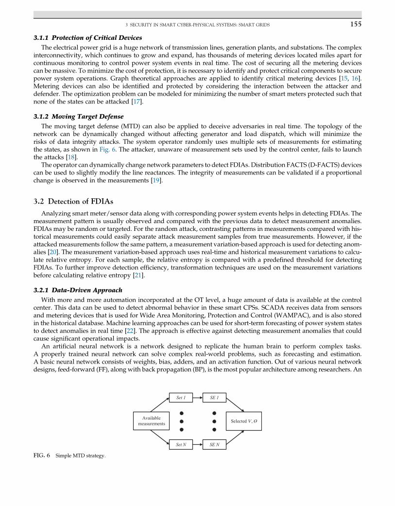
The moving target defense (MTD) can also be applied to deceive adversaries in real time. The topology of thenetwork can be dynamically changed without affecting generator and load dispatch, which will minimize therisks of data integrity attacks. The system operator randomly uses multiple sets of measurements for estimatingthe states, as shown in Fig. 6. The attacker, unaware of measurement sets used by the control center, fails to launchthe attacks [18].
The operator can dynamically change network parameters to detect FDIAs. Distribution FACTS (D-FACTS) devicescan be used to slightly modify the line reactances. The integrity of measurements can be validated if a proportionalchange is observed in the measurements [19].
3.2 Detection of FDIAs
Analyzing smart meter/sensor data along with corresponding power system events helps in detecting FDIAs. Themeasurement pattern is usually observed and compared with the previous data to detect measurement anomalies.FDIAs may be random or targeted. For the random attack, contrasting patterns in measurements compared with his-torical measurements could easily separate attack measurement samples from true measurements. However, if theattackedmeasurements follow the same pattern, ameasurement variation-based approach is used for detecting anom-alies [20]. The measurement variation-based approach uses real-time and historical measurement variations to calcu-late relative entropy. For each sample, the relative entropy is compared with a predefined threshold for detectingFDIAs. To further improve detection efficiency, transformation techniques are used on the measurement variationsbefore calculating relative entropy [21].
3.2.1 Data-Driven Approach
With more and more automation incorporated at the OT level, a huge amount of data is available at the controlcenter. This data can be used to detect abnormal behavior in these smart CPSs. SCADA receives data from sensorsand metering devices that is used for Wide Area Monitoring, Protection and Control (WAMPAC), and is also storedin the historical database. Machine learning approaches can be used for short-term forecasting of power system statesto detect anomalies in real time [22]. The approach is effective against detecting measurement anomalies that couldcause significant operational impacts.
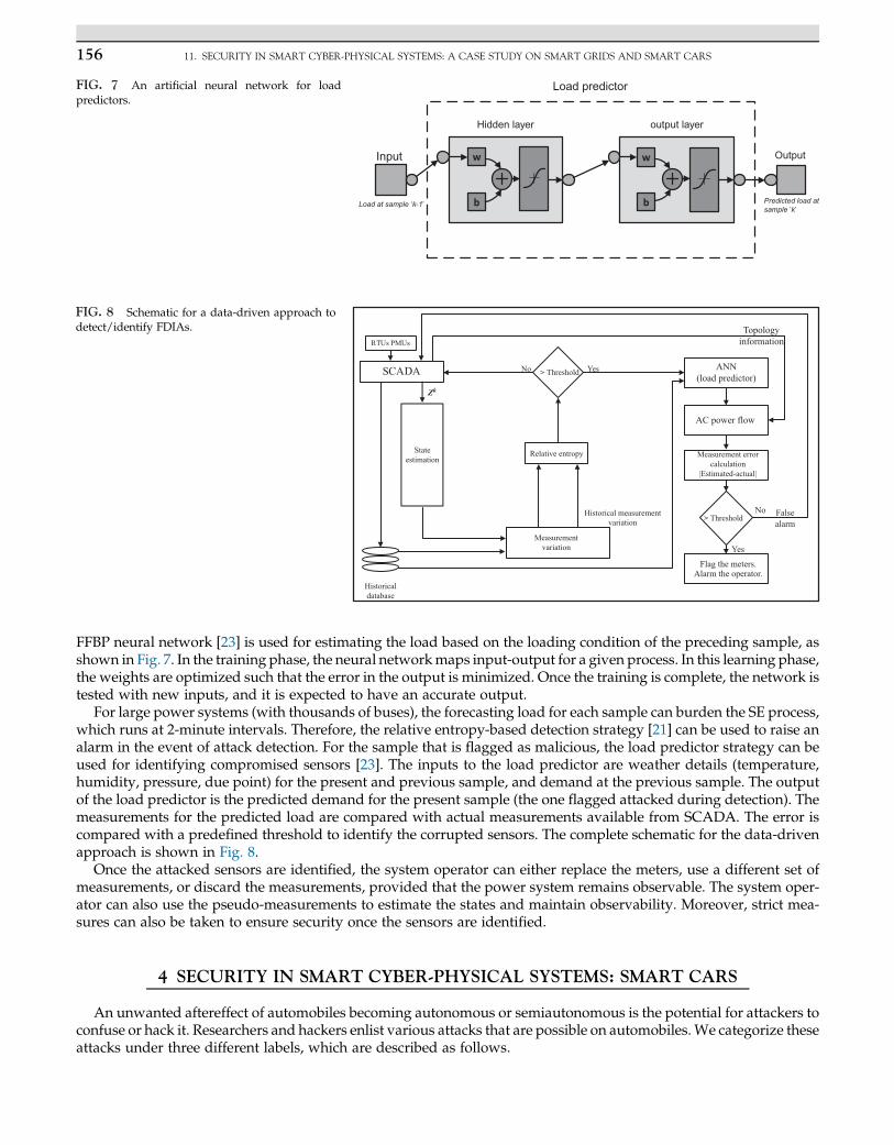
An artificial neural network is a network designed to replicate the human brain to perform complex tasks.A properly trained neural network can solve complex real-world problems, such as forecasting and estimation.A basic neural network consists of weights, bias, adders, and an activation function. Out of various neural networkdesigns, feed-forward (FF), along with back propagation (BP), is the most popular architecture among researchers. An
FIG. 6 Simple MTD strategy.
Load predictor
Hidden layer output layer
Output
Predicted load atsample ‘k’
Load at sample ‘k-1’
Input
FIG. 7 An artificial neural network for loadpredictors.
Threshold YesNo
Stateestimation
Relative entropy
Historical measurementvariation
Measurementvariation
Historicaldatabase
Flag the meters.Alarm the operator.
No
Yes
Falsealarm
Threshold
Measurement errorcalculation
|Estimated-actual|
AC power flow
ANN(load predictor)
Topologyinformation
Zk
FIG. 8 Schematic for a data-driven approach todetect/identify FDIAs.
156 11. SECURITY IN SMART CYBER-PHYSICAL SYSTEMS: A CASE STUDY ON SMART GRIDS AND SMART CARS
FFBP neural network [23] is used for estimating the load based on the loading condition of the preceding sample, asshown in Fig. 7. In the training phase, the neural networkmaps input-output for a given process. In this learning phase,the weights are optimized such that the error in the output is minimized. Once the training is complete, the network istested with new inputs, and it is expected to have an accurate output.
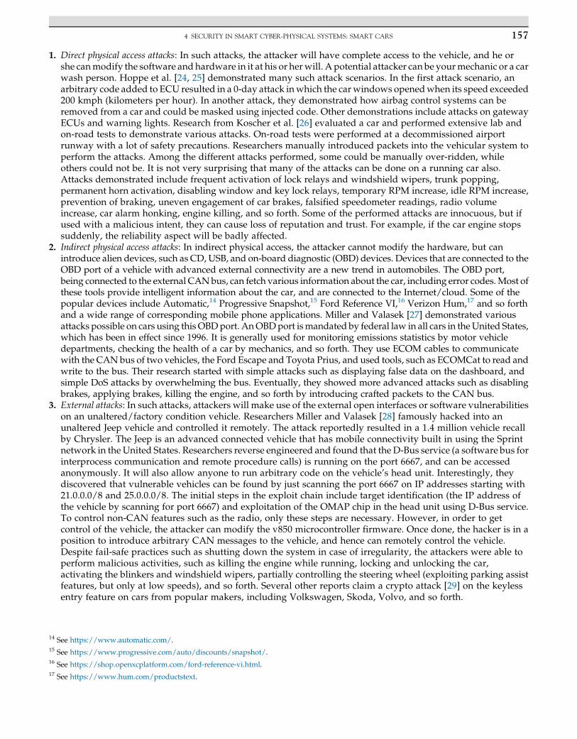
For large power systems (with thousands of buses), the forecasting load for each sample can burden the SE process,which runs at 2-minute intervals. Therefore, the relative entropy-based detection strategy [21] can be used to raise analarm in the event of attack detection. For the sample that is flagged as malicious, the load predictor strategy can beused for identifying compromised sensors [23]. The inputs to the load predictor are weather details (temperature,humidity, pressure, due point) for the present and previous sample, and demand at the previous sample. The outputof the load predictor is the predicted demand for the present sample (the one flagged attacked during detection). Themeasurements for the predicted load are compared with actual measurements available from SCADA. The error iscompared with a predefined threshold to identify the corrupted sensors. The complete schematic for the data-drivenapproach is shown in Fig. 8.
Once the attacked sensors are identified, the system operator can either replace the meters, use a different set ofmeasurements, or discard the measurements, provided that the power system remains observable. The system oper-ator can also use the pseudo-measurements to estimate the states and maintain observability. Moreover, strict mea-sures can also be taken to ensure security once the sensors are identified.
4 SECURITY IN SMART CYBER-PHYSICAL SYSTEMS: SMART CARS
An unwanted aftereffect of automobiles becoming autonomous or semiautonomous is the potential for attackers toconfuse or hack it. Researchers and hackers enlist various attacks that are possible on automobiles.We categorize theseattacks under three different labels, which are described as follows.
1574 SECURITY IN SMART CYBER-PHYSICAL SYSTEMS: SMART CARS
1. Direct physical access attacks: In such attacks, the attacker will have complete access to the vehicle, and he orshe canmodify the software and hardware in it at his or herwill. A potential attacker can be yourmechanic or a carwash person. Hoppe et al. [24, 25] demonstrated many such attack scenarios. In the first attack scenario, anarbitrary code added to ECU resulted in a 0-day attack inwhich the car windows openedwhen its speed exceeded200 kmph (kilometers per hour). In another attack, they demonstrated how airbag control systems can beremoved from a car and could be masked using injected code. Other demonstrations include attacks on gatewayECUs and warning lights. Research from Koscher et al. [26] evaluated a car and performed extensive lab andon-road tests to demonstrate various attacks. On-road tests were performed at a decommissioned airportrunway with a lot of safety precautions. Researchers manually introduced packets into the vehicular system toperform the attacks. Among the different attacks performed, some could be manually over-ridden, whileothers could not be. It is not very surprising that many of the attacks can be done on a running car also.Attacks demonstrated include frequent activation of lock relays and windshield wipers, trunk popping,permanent horn activation, disabling window and key lock relays, temporary RPM increase, idle RPM increase,prevention of braking, uneven engagement of car brakes, falsified speedometer readings, radio volumeincrease, car alarm honking, engine killing, and so forth. Some of the performed attacks are innocuous, but ifused with a malicious intent, they can cause loss of reputation and trust. For example, if the car engine stopssuddenly, the reliability aspect will be badly affected.
2. Indirect physical access attacks: In indirect physical access, the attacker cannot modify the hardware, but canintroduce alien devices, such as CD, USB, and on-board diagnostic (OBD) devices. Devices that are connected to theOBD port of a vehicle with advanced external connectivity are a new trend in automobiles. The OBD port,being connected to the external CANbus, can fetch various information about the car, including error codes.Most ofthese tools provide intelligent information about the car, and are connected to the Internet/cloud. Some of thepopular devices include Automatic,14 Progressive Snapshot,15 Ford Reference VI,16 Verizon Hum,17 and so forthand a wide range of corresponding mobile phone applications. Miller and Valasek [27] demonstrated variousattacks possible on cars using this OBDport. AnOBDport ismandated by federal law in all cars in theUnited States,which has been in effect since 1996. It is generally used for monitoring emissions statistics by motor vehicledepartments, checking the health of a car by mechanics, and so forth. They use ECOM cables to communicatewith the CAN bus of two vehicles, the Ford Escape and Toyota Prius, and used tools, such as ECOMCat to read andwrite to the bus. Their research started with simple attacks such as displaying false data on the dashboard, andsimple DoS attacks by overwhelming the bus. Eventually, they showed more advanced attacks such as disablingbrakes, applying brakes, killing the engine, and so forth by introducing crafted packets to the CAN bus.
3. External attacks: In such attacks, attackers will make use of the external open interfaces or software vulnerabilitieson an unaltered/factory condition vehicle. Researchers Miller and Valasek [28] famously hacked into anunaltered Jeep vehicle and controlled it remotely. The attack reportedly resulted in a 1.4 million vehicle recallby Chrysler. The Jeep is an advanced connected vehicle that has mobile connectivity built in using the Sprintnetwork in the United States. Researchers reverse engineered and found that the D-Bus service (a software bus forinterprocess communication and remote procedure calls) is running on the port 6667, and can be accessedanonymously. It will also allow anyone to run arbitrary code on the vehicle’s head unit. Interestingly, theydiscovered that vulnerable vehicles can be found by just scanning the port 6667 on IP addresses starting with21.0.0.0/8 and 25.0.0.0/8. The initial steps in the exploit chain include target identification (the IP address ofthe vehicle by scanning for port 6667) and exploitation of the OMAP chip in the head unit using D-Bus service.To control non-CAN features such as the radio, only these steps are necessary. However, in order to getcontrol of the vehicle, the attacker can modify the v850 microcontroller firmware. Once done, the hacker is in aposition to introduce arbitrary CAN messages to the vehicle, and hence can remotely control the vehicle.Despite fail-safe practices such as shutting down the system in case of irregularity, the attackers were able toperform malicious activities, such as killing the engine while running, locking and unlocking the car,activating the blinkers and windshield wipers, partially controlling the steering wheel (exploiting parking assistfeatures, but only at low speeds), and so forth. Several other reports claim a crypto attack [29] on the keylessentry feature on cars from popular makers, including Volkswagen, Skoda, Volvo, and so forth.
14 See https://www.automatic.com/.15 See https://www.progressive.com/auto/discounts/snapshot/.16 See https://shop.openxcplatform.com/ford-reference-vi.html.17 See https://www.hum.com/productstext.
158 11. SECURITY IN SMART CYBER-PHYSICAL SYSTEMS: A CASE STUDY ON SMART GRIDS AND SMART CARS
4.1 Countermeasures
One of the core problems with the vehicular architecture is the presence of comparatively primitive bus technology,lacking cutting-edge security features, with far more sophisticated subsystems running on top. For example, the CANbus is a broadcast-based bus in which all connected devices can see all the traffic, and there is no in-built concept ofauthentication or authorization. Any message on the wire is authenticated by default. This enables an attacker tointroduce well-formed packets on to the wire to perform malicious activities. Research enlists two categories oftechniques to secure the environment, which are described in the following sections.
4.1.1 Attack Prevention Techniques
The first approach is to prevent the attacks from happening. According to Wolfe et al. [30], a combination ofhardware protection techniques, software protection techniques, and secure communication are required to achievethis. Newer protocols (varying in capabilities, speed, implementation overhead, and so forth) and the modification ofexisting protocols are proposed with this intent. LCAP [31] (Lightweight CAN Authentication Protocol) is one suchprotocol, with minimum overhead, that is a modification to the existing CAN network. The technique is based on apreshared key and magic number exchanged between the sender and receiver. At the beginning of a drive cycle, alldevices perform an initial setup, and will have a session key, HMAC key, and a channel initial magic number, whichare used for subsequent message transmissions. For data exchange, the sender will append the magic number to themessage and encrypt it using a session key. The receiver will authenticate the message using the magic number afterdecrypting it. However, this protocol will have the overhead for cryptographic calculations.
CANAuth [32] is another proposed protocol that is backward compatible. This protocol also depends on a pre-shared key stored in a tamper-proof location with each of the entities. A session key will be generated using thepreshared key and it will be used for authenticating messages. In CANAuth, considering the hard constraints on timeand message length, the authentication data is transmitted out of band using the CAN+ [33] protocol. Each authen-tication message will have a 32-bit counter value to prevent replay attacks and an 80-bit signature with this protocol.
LiBrA-CAN [34] is another proposed protocol to prevent attacks that uses CAN-FD18 (a newer CAN protocol withflexible data rates). LiBrA-CAN presents two new paradigms, namely, key splitting and MAC mixing for messageauthentication. The protocol can be used in a master oriented flavor (a node with higher computational capabilitiesis used for authentication), which includes centralized, cumulative, and load balanced authentication schemes, ordistributed flavor, which includes two-stage authentication and multimaster authentication schemes. In comparisonwith other protocols, they have efficient forgery detection using MAC mixing and lesser authentication delays.
Apart from protocol-specific drawbacks such as time constraints, the requirement of preshared keys and highercomputational power are some disadvantages of such techniques. Another major drawback for this class of techniquesis that we can only protect future vehicles, not the present ones on the road. Moreover, the automotive domain isa huge industry, and it requires a long time to change. Koscher et al. [26] describe these stringent “operational andeconomic realities” in the automotive industry and explain the importance of a detection strategy for automobiles.
4.1.2 Attack Detection and Mitigation
The second strategy to make the automotive domain safe is attack detection and mitigation. Different companieshave come up with automotive intrusion detection systems. Panasonic Corporation is developing an intrusion detec-tion and prevention system19 (IDPS) that combines host intrusion detection technology (which combines behavioralinformation), in-vehicle device-type intrusion detection technology (it monitors and detects unauthorized commandsin the in-vehicle network, both CAN-based and Ethernet-based), and cloud-type vehicle intrusion detection technol-ogy (detects intrusion by analyzing logs collected from different vehicles usingmachine learning). Karamba Security20
is another company that develops tools such as Karamba Carwall (it generates policies based on factory settings andembeds them into ECUs to continuously validate actions at runtime) and Karamba SafeCAN (it authenticates andhardens in-car network communications, helping ECUs to ignore commands from invalid ECUs or physical hacks).Escrypt21 is yet another company that develops an IDPS for vehicles. Their products, CycurIDS and CycurGUARD,analyze data from multiple vehicles and detect potential intrusions. We can classify the basic research in this domaininto two subcategories based on whether the technique uses a semantic understanding of the underlying data.
18 See https://can-newsletter.org/assets/files/ttmedia/raw/e5740b7b5781b8960f55efcc2b93edf8.pdf.19 See http://itsworldcongress2017.org/wp-content/uploads/2017/11/kishikawa_20171025.pdf.20 See https://karambasecurity.com/products.21 See https://www.escrypt.com/en/solutions-overview.
1594 SECURITY IN SMART CYBER-PHYSICAL SYSTEMS: SMART CARS
4.1.2.1 Statistics-Oriented Techniques
Research enlists different techniques for attack detection andmitigation. One such research direction is by applyingmachine learning techniques on raw CAN messages without considering the semantics of the messages.
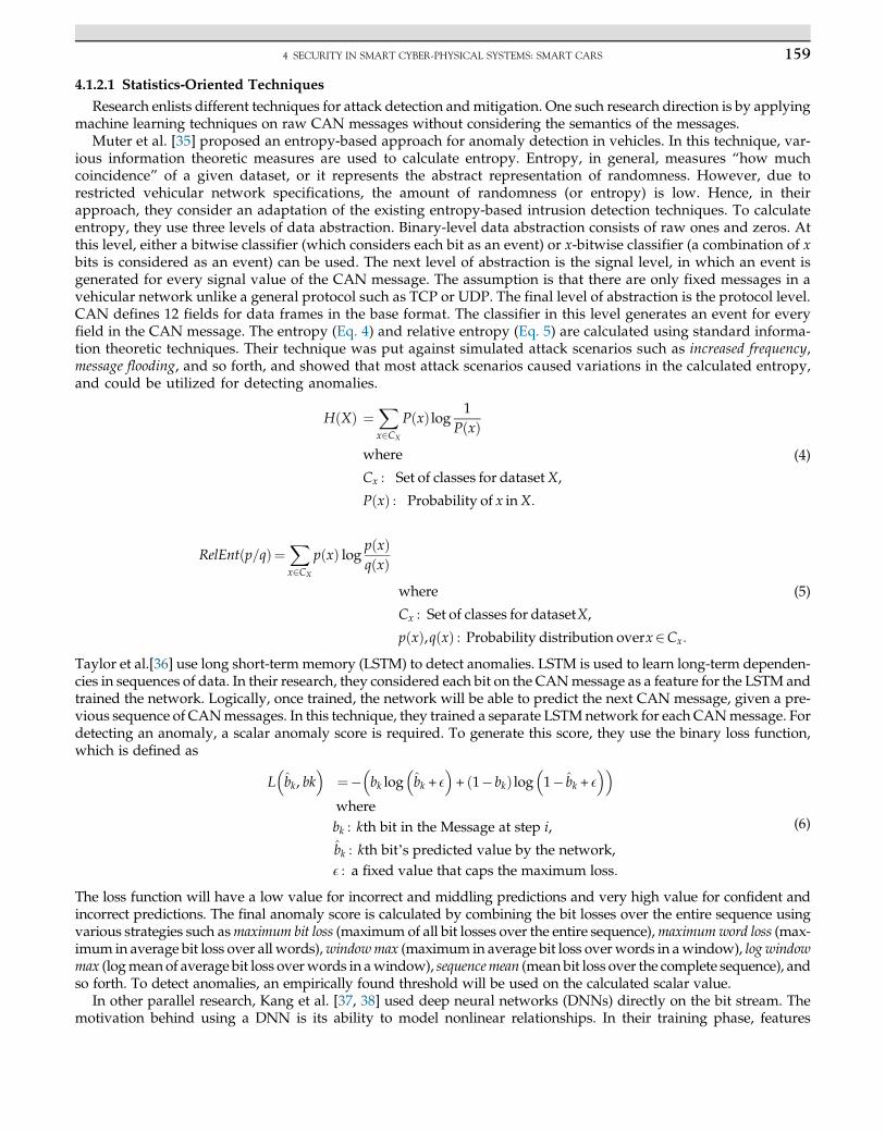
Muter et al. [35] proposed an entropy-based approach for anomaly detection in vehicles. In this technique, var-ious information theoretic measures are used to calculate entropy. Entropy, in general, measures “how muchcoincidence” of a given dataset, or it represents the abstract representation of randomness. However, due torestricted vehicular network specifications, the amount of randomness (or entropy) is low. Hence, in theirapproach, they consider an adaptation of the existing entropy-based intrusion detection techniques. To calculateentropy, they use three levels of data abstraction. Binary-level data abstraction consists of raw ones and zeros. Atthis level, either a bitwise classifier (which considers each bit as an event) or x-bitwise classifier (a combination of xbits is considered as an event) can be used. The next level of abstraction is the signal level, in which an event isgenerated for every signal value of the CAN message. The assumption is that there are only fixed messages in avehicular network unlike a general protocol such as TCP or UDP. The final level of abstraction is the protocol level.CAN defines 12 fields for data frames in the base format. The classifier in this level generates an event for everyfield in the CAN message. The entropy (Eq. 4) and relative entropy (Eq. 5) are calculated using standard informa-tion theoretic techniques. Their technique was put against simulated attack scenarios such as increased frequency,message flooding, and so forth, and showed that most attack scenarios caused variations in the calculated entropy,and could be utilized for detecting anomalies.
HðXÞ ¼Xx2CX
PðxÞ log 1PðxÞ
where
Cx : Set of classes for datasetX,
PðxÞ : Probability of x inX:
(4)
RelEnt p=qð Þ¼Xx2CX
p xð Þ log p xð Þq xð Þ
where
Cx : Set of classes for datasetX,
p xð Þ,q xð Þ : Probability distribution overx2Cx:
(5)
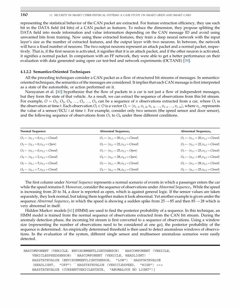
Taylor et al.[36] use long short-term memory (LSTM) to detect anomalies. LSTM is used to learn long-term dependen-cies in sequences of data. In their research, they considered each bit on the CANmessage as a feature for the LSTM andtrained the network. Logically, once trained, the network will be able to predict the next CAN message, given a pre-vious sequence of CANmessages. In this technique, they trained a separate LSTMnetwork for each CANmessage. Fordetecting an anomaly, a scalar anomaly score is required. To generate this score, they use the binary loss function,which is defined as
L b̂k, bk� �
¼� bk log b̂k + E� �
+ 1�bkð Þ log 1� b̂k + E� �� �
wherebk : kth bit in the Message at step i,
b̂k : kth bit’s predicted value by the network,E : a fixed value that caps the maximum loss:
(6)
The loss function will have a low value for incorrect and middling predictions and very high value for confident andincorrect predictions. The final anomaly score is calculated by combining the bit losses over the entire sequence usingvarious strategies such asmaximum bit loss (maximum of all bit losses over the entire sequence),maximumword loss (max-imum in average bit loss over all words),windowmax (maximum in average bit loss overwords in awindow), log windowmax (logmean of average bit loss overwords in awindow), sequencemean (mean bit loss over the complete sequence), andso forth. To detect anomalies, an empirically found threshold will be used on the calculated scalar value.
In other parallel research, Kang et al. [37, 38] used deep neural networks (DNNs) directly on the bit stream. Themotivation behind using a DNN is its ability to model nonlinear relationships. In their training phase, features
160 11. SECURITY IN SMART CYBER-PHYSICAL SYSTEMS: A CASE STUDY ON SMART GRIDS AND SMART CARS
representing the statistical behavior of the CAN packet are extracted. For feature extraction efficiency, they use eachbit in the DATA field (64 bits) of a CAN packet as features. To reduce the dimension, they propose splitting theDATA field into mode information and value information depending on the CAN message ID and avoid usingunwanted bits from training. Now using these extracted features, they train a deep neural network with the inputlayer’s size as the number of extracted features, and the output layer with two neurons. In between, the networkwill have a fixed number of neurons. The two output neurons represent an attack packet and a normal packet, respec-tively. That is, if the first neuron is activated, it signifies that it is an attack packet, and if the other neuron is activated,it signifies a normal packet. In comparison with an FF network, they were able to get a better performance on theirevaluation with data generated using open car test-bed and network experiments (OCTANE) [39].
4.1.2.2 Semantics-Oriented Techniques
All the preceding techniques consider a CAN packet as a flow of structured bit streams of messages. In semantics-oriented techniques, the semantics of themessages are considered. It implies that each CANmessage is first interpretedas a state of the automobile, or action performed on it.
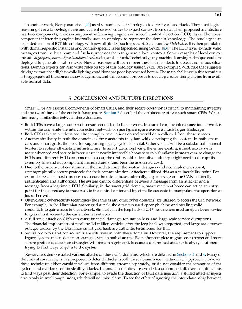
Narayanan et al. [40] hypothesize that the flow of packets in a car is not just a flow of independent messages,but they form the state of that vehicle. As a result, we can extract the sequence of observations from this bit stream.For example, O ¼ O1, O2, O3, …, Ot, …, On can be a sequence of n observations extracted from a car, where Ot isthe observation at time t. Each observationOt 2O is a vectorOt¼ hvt, 1, vt, 2, vt, 3,…, vt, i,…, vt, mi, where vt, i representsthe value of a sensor/ECU i at time t. For example, consider only two sensors (the speed sensor and door sensor),and the following sequence of observations from O1 to O6 under three different conditions.
Normal Sequence Abnormal Sequence1 Abnormal Sequence2
O1 hv1,1 ¼ 0,v1,2¼Closedi O1 hv1,1 ¼ 20,v1,2¼Closedi O1 hv1,1¼ 20,v1,2 ¼ClosediO2 hv2,1 ¼ 0,v2,2¼Openi O2 hv2,1 ¼ 22,v2,2¼Closedi O2 hv2,1¼ 22,v2,2 ¼ClosediO3 hv3,1 ¼ 0,v3,2¼Closedi O3 hv3,1 ¼ 25,v3,2¼Openi O3 hv3,1¼ 25,v3,2 ¼ClosediO4 hv4,1 ¼ 2,v4,2¼Closedi O4 hv4,1 ¼ 28,v4,2¼Openi O4 hv4,1¼ 85,v4,2 ¼ClosediO5 hv5,1 ¼ 5,v5,2¼Closedi O5 hv5,1 ¼ 30,v5,2¼Closedi O5 hv5,1¼ 28,v5,2 ¼ClosediO6 hv6,1 ¼ 7,v6,2¼Closedi O6 hv6,1 ¼ 34,v6,2¼Closedi O6 hv6,1¼ 25,v6,2 ¼Closedi
The first column under Normal Sequence represents a normal scenario of events in which a passenger enters the carwhile the speed remains 0. However, consider the sequence of observations underAbnormal Sequence1. While the speedis increasing from 20 to 34, a door is reported as open, which is against general logic. If the sensor values are takenseparately, they look normal, but taking them togethermakes it look abnormal. Yet another example is given under thesequence Abnormal Sequence2 in which the speed is showing a sudden spike from 25! 85 and then 85! 28 which isvery abnormal in itself.
Hidden Markov models [41] (HMM) are used to find the posterior probability of a sequence. In this technique, anHMM model is trained from the normal sequence of observations extracted from the CAN bit stream. During theanomaly detection phase, the incoming bit stream is first converted to a sequence of observations. Using a windowsize (representing the number of observations need to be considered at one go), the posterior probability of thesequence is determined. An empirically determined threshold is then used to detect anomalous windows of observa-tions. In the evaluation of the system, different single sensor and multisensor anomalous scenarios were easilydetected.
HASCOMPONENT (VEHICLE, ENVIRONMENTLIGHTSENSOR) ^ HASCOMPONENT (VEHICLE,
VEHICLESPEEDSENSOR) ^ HASCOMPONENT (VEHICLE, HEADLIGHT) ^
HASSTATEVALUE (ENVIRONMENTLIGHTSENSOR, "LOW") ^ HASSTATEVALUE
(HEADLIGHT, "OFF") ^ HASSTATEVALUE (VEHICLESPEED, "HIGH") ==>
HASSTATEVALUE (CURRENTVEHICLESTATE, "ANOMALOUS NO LIGHT")}
1615 CONCLUSION AND FUTURE DIRECTIONS
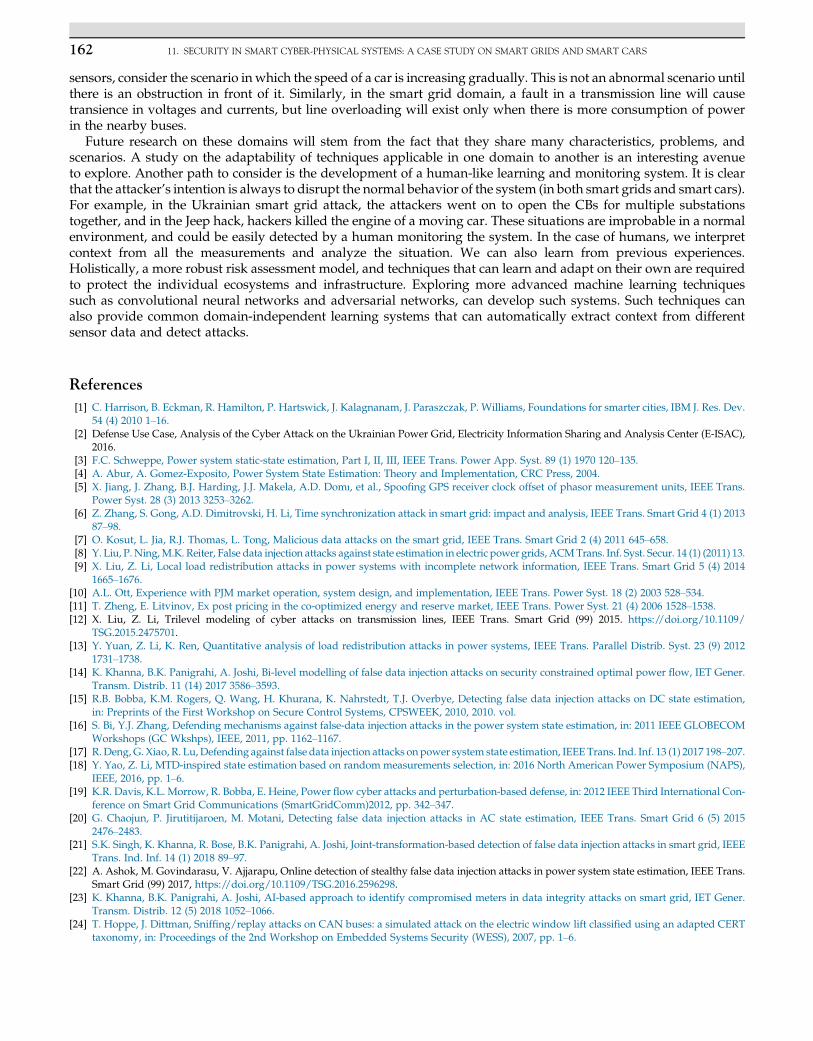
In another work, Narayanan et al. [42] used semantic web technologies to detect various attacks. They used logicalreasoning over a knowledge base and current sensor values to extract context from data. Their proposed architecturehas two components, a cross-component inferencing engine and a local context detection (LCD) layer. The cross-component inferencing engine internally uses an ontology to represent the domain knowledge. The ontology is anextended version of IOT-lite ontologywith new attributes, such as senseAttribute and hasStateValue. It is then populatedwith domain-specific instances and domain-specific rules (specified using SWRL [43]). The LCD layer extracts validmessages from the bit stream and further processes them to generate local contexts. Some examples of local contextinclude highSpeed, normalSpeed, suddenAcceleration, and so forth. Technically, any machine learning technique could bedeployed to generate local contexts. Now a reasoner will reason over these local contexts to detect anomalous situa-tions. Domain experts can also write rules on top of this ontology using SWRL. An example SWRL rule that suggestsdrivingwithout headlights while lighting conditions are poor is presented herein. Themain challenge in this techniqueis to aggregate all the domain knowledge rules, and this research proposes to develop a rule mining engine from avail-able normal data.
5 CONCLUSION AND FUTURE DIRECTIONS
Smart CPSs are essential components of Smart Cities, and their secure operation is critical to maintaining integrityand trustworthiness of the entire infrastructure. Section 2 described the architecture of two such smart CPSs. We canfind many similarities between these domains.
• Both CPSs have a large number of sensors connected to the network. In a smart car, the interconnection network iswithin the car, while the interconnection network of smart grids spans across a much larger landscape.
• Both CPSs take smart decisions after complex calculations on real-world data collected from these sensors.• Another similarity in both the domains is the constraints they had while developing the system. In both smart
cars and smart grids, the need for supporting legacy systems is vital. Otherwise, it will be a substantial financialburden to replace all existing infrastructure. In smart grids, replacing the entire existing infrastructure withmore advanced and secure infrastructure is nearly impossible because of this. Similarly in smart cars, to change theECUs and different ECU components in a car, the century-old automotive industry might need to disrupt itsassembly line and subcomponent manufacturers (and bear the associated cost).
• Due to the presence of constraints in their architecture, the system designers did not implement robust,cryptographically secure protocols for their communication. Attackers utilized this as a vulnerability point. Forexample, because most cars use less secure broadcast buses internally, any message on the CAN is directlyauthenticated and authorized. The system cannot differentiate between a message from an attacker and amessage from a legitimate ECU. Similarly, in the smart grid domain, smart meters at home can act as an entrypoint for the adversary to trace back to the control center and inject malicious code to manipulate the operation athis or her will.
• Often classic cybersecurity techniques (the same as any other cyber domains) are utilized to access the CPS network.For example, in the Ukrainian power grid attack, the attackers used spear phishing and stealing validcredentials to gain access to the network. Similarly, in the Jeep hack of 2016, researchers used an open Dbus serviceto gain initial access to the car’s internal network.
• A full-scale attack on CPSs can cause financial damage, reputation loss, and large-scale service disruptions.The financial implications of recalling 1.4 million vehicles after the Jeep hack was reported, and large-scale poweroutages caused by the Ukrainian smart grid hack are authentic testimonies for this.
• Secure protocols and control units are solutions in both these domains. However, the requirement to supportlegacy systemsmakes detection strategies vital in both domains. Even after complete migrations to newer andmoresecure protocols, detection strategies will remain significant, because a determined attacker is always out theretrying to find ways to get into the system.
Researchers demonstrated various attacks on these CPS domains, which are detailed in Sections 3 and 4. Many ofthe current countermeasures proposed to defend attacks in both these domains use a data-driven approach. However,these techniques either consider values from different streams separately, or do not consider the semantics of thesystem, and overlook certain stealthy attacks. If domain semantics are avoided, a determined attacker can utilize thisto find ways past their detection. For example, to evade the detection of fault data injection, a skilled attacker injectserrors only in small magnitudes, which will not raise alarm. To see the effect of ignoring the interrelationship between
162 11. SECURITY IN SMART CYBER-PHYSICAL SYSTEMS: A CASE STUDY ON SMART GRIDS AND SMART CARS
sensors, consider the scenario in which the speed of a car is increasing gradually. This is not an abnormal scenario untilthere is an obstruction in front of it. Similarly, in the smart grid domain, a fault in a transmission line will causetransience in voltages and currents, but line overloading will exist only when there is more consumption of powerin the nearby buses.
Future research on these domains will stem from the fact that they share many characteristics, problems, andscenarios. A study on the adaptability of techniques applicable in one domain to another is an interesting avenueto explore. Another path to consider is the development of a human-like learning and monitoring system. It is clearthat the attacker’s intention is always to disrupt the normal behavior of the system (in both smart grids and smart cars).For example, in the Ukrainian smart grid attack, the attackers went on to open the CBs for multiple substationstogether, and in the Jeep hack, hackers killed the engine of a moving car. These situations are improbable in a normalenvironment, and could be easily detected by a human monitoring the system. In the case of humans, we interpretcontext from all the measurements and analyze the situation. We can also learn from previous experiences.Holistically, a more robust risk assessment model, and techniques that can learn and adapt on their own are requiredto protect the individual ecosystems and infrastructure. Exploring more advanced machine learning techniquessuch as convolutional neural networks and adversarial networks, can develop such systems. Such techniques canalso provide common domain-independent learning systems that can automatically extract context from differentsensor data and detect attacks.
References
[1] C. Harrison, B. Eckman, R. Hamilton, P. Hartswick, J. Kalagnanam, J. Paraszczak, P. Williams, Foundations for smarter cities, IBM J. Res. Dev.54 (4) 2010 1–16.
[2] Defense Use Case, Analysis of the Cyber Attack on the Ukrainian Power Grid, Electricity Information Sharing and Analysis Center (E-ISAC),2016.
[3] F.C. Schweppe, Power system static-state estimation, Part I, II, III, IEEE Trans. Power App. Syst. 89 (1) 1970 120–135.[4] A. Abur, A. Gomez-Exposito, Power System State Estimation: Theory and Implementation, CRC Press, 2004.[5] X. Jiang, J. Zhang, B.J. Harding, J.J. Makela, A.D. Domı, et al., Spoofing GPS receiver clock offset of phasor measurement units, IEEE Trans.
Power Syst. 28 (3) 2013 3253–3262.[6] Z. Zhang, S. Gong, A.D. Dimitrovski, H. Li, Time synchronization attack in smart grid: impact and analysis, IEEE Trans. Smart Grid 4 (1) 2013
87–98.[7] O. Kosut, L. Jia, R.J. Thomas, L. Tong, Malicious data attacks on the smart grid, IEEE Trans. Smart Grid 2 (4) 2011 645–658.[8] Y. Liu, P.Ning,M.K. Reiter, False data injection attacks against state estimation in electric power grids,ACMTrans. Inf. Syst. Secur. 14 (1) (2011) 13.[9] X. Liu, Z. Li, Local load redistribution attacks in power systems with incomplete network information, IEEE Trans. Smart Grid 5 (4) 2014
1665–1676.[10] A.L. Ott, Experience with PJM market operation, system design, and implementation, IEEE Trans. Power Syst. 18 (2) 2003 528–534.[11] T. Zheng, E. Litvinov, Ex post pricing in the co-optimized energy and reserve market, IEEE Trans. Power Syst. 21 (4) 2006 1528–1538.[12] X. Liu, Z. Li, Trilevel modeling of cyber attacks on transmission lines, IEEE Trans. Smart Grid (99) 2015. https://doi.org/10.1109/
TSG.2015.2475701.[13] Y. Yuan, Z. Li, K. Ren, Quantitative analysis of load redistribution attacks in power systems, IEEE Trans. Parallel Distrib. Syst. 23 (9) 2012
1731–1738.[14] K. Khanna, B.K. Panigrahi, A. Joshi, Bi-level modelling of false data injection attacks on security constrained optimal power flow, IET Gener.
Transm. Distrib. 11 (14) 2017 3586–3593.[15] R.B. Bobba, K.M. Rogers, Q. Wang, H. Khurana, K. Nahrstedt, T.J. Overbye, Detecting false data injection attacks on DC state estimation,
in: Preprints of the First Workshop on Secure Control Systems, CPSWEEK, 2010, 2010. vol.[16] S. Bi, Y.J. Zhang, Defending mechanisms against false-data injection attacks in the power system state estimation, in: 2011 IEEE GLOBECOM
Workshops (GC Wkshps), IEEE, 2011, pp. 1162–1167.[17] R. Deng, G. Xiao, R. Lu,Defending against false data injection attacks on power system state estimation, IEEETrans. Ind. Inf. 13 (1) 2017 198–207.[18] Y. Yao, Z. Li, MTD-inspired state estimation based on random measurements selection, in: 2016 North American Power Symposium (NAPS),
IEEE, 2016, pp. 1–6.[19] K.R. Davis, K.L. Morrow, R. Bobba, E. Heine, Power flow cyber attacks and perturbation-based defense, in: 2012 IEEE Third International Con-
ference on Smart Grid Communications (SmartGridComm)2012, pp. 342–347.[20] G. Chaojun, P. Jirutitijaroen, M. Motani, Detecting false data injection attacks in AC state estimation, IEEE Trans. Smart Grid 6 (5) 2015
2476–2483.[21] S.K. Singh, K. Khanna, R. Bose, B.K. Panigrahi, A. Joshi, Joint-transformation-based detection of false data injection attacks in smart grid, IEEE
Trans. Ind. Inf. 14 (1) 2018 89–97.[22] A. Ashok, M. Govindarasu, V. Ajjarapu, Online detection of stealthy false data injection attacks in power system state estimation, IEEE Trans.
Smart Grid (99) 2017, https://doi.org/10.1109/TSG.2016.2596298.[23] K. Khanna, B.K. Panigrahi, A. Joshi, AI-based approach to identify compromised meters in data integrity attacks on smart grid, IET Gener.
Transm. Distrib. 12 (5) 2018 1052–1066.[24] T. Hoppe, J. Dittman, Sniffing/replay attacks on CAN buses: a simulated attack on the electric window lift classified using an adapted CERT
taxonomy, in: Proceedings of the 2nd Workshop on Embedded Systems Security (WESS), 2007, pp. 1–6.
163REFERENCES
[25] T. Hoppe, S. Kiltz, J. Dittmann, Security threats to automotive CAN networks-practical examples and selected short-term countermeasures,in: Computer Safety, Reliability, and Security, Springer, 2008, pp. 235–248.
[26] K. Koscher, A. Czeskis, F. Roesner, S. Patel, T. Kohno, S. Checkoway, D. McCoy, B. Kantor, D. Anderson, H. Shacham, et al., Experimentalsecurity analysis of a modern automobile, in: 2010 IEEE Symposium on Security and Privacy (SP), IEEE, 2010, pp. 447–462.
[27] C. Miller, C. Valasek, Adventures in automotive networks and control units, in: DEF CON 21 Hacking Conference, Las Vegas, NV, 2013.[28] C. Miller, C. Valasek, Remote exploitation of an unaltered passenger vehicle, Tech. Rep., Blackhat, 2015.[29] D. Storm, Hack to steal cars with keyless ignition: Volkswagen spent 2 years hiding flaw. Available from: http://www.computerworld.com/
article/2971826/cybercrime-hacking/hack-to-steal-cars-with-keyless-ignition-volkswagen-spent-2-years-hiding-flaw.html.[30] M. Wolf, A. Weimerskirch, T. Wollinger, State of the art: embedding security in vehicles, EURASIP J. Embed. Syst. 2007 (1) 2007 074706.[31] A. Hazem, H.A. Fahmy, LCAP-A lightweight CAN authentication protocol for securing in-vehicle networks, in: 10th ESCAR Embedded Secu-
rity in Cars Conference, Berlin, Germany, 6, 2012. vol.[32] A. Van Herrewege, D. Singelee, I. Verbauwhede, CANAuth—a simple, backward compatible broadcast authentication protocol for CAN bus,
in: ECRYPT Workshop on Lightweight Cryptography, 2011.[33] T. Ziermann, S.Wildermann, J. Teich, CAN+: a new backward-compatible Controller AreaNetwork (CAN) protocol with up to 16� higher data
rates, in: Proceedings of the Conference on Design, Automation and Test in Europe, European Design and Automation Association, 2009,pp. 1088–1093.
[34] B. Groza, S. Murvay, A. VanHerrewege, I. Verbauwhede, LiBrA-CAN: lightweight broadcast authentication for controller area networks, ACMTrans. Embed. Comput. Syst. 16 (3) 2017 90.
[35] M. M€uter, N. Asaj, Entropy-based anomaly detection for in-vehicle networks, in: 2011 IEEE Intelligent Vehicles Symposium (IV), IEEE, 2011,pp. 1110–1115.
[36] A. Taylor, S. Leblanc, N. Japkowicz, Anomaly detection in automobile control network data with long short-term memory networks, in: 2016IEEE International Conference on Data Science and Advanced Analytics (DSAA), IEEE, 2016, pp. 130–139.
[37] M.-J. Kang, J.-W. Kang, A novel intrusion detection method using deep neural network for in-vehicle network security, in: 2016 IEEE 83rdVehicular Technology Conference (VTC Spring), IEEE, 2016, pp. 1–5.
[38] M.-J. Kang, J.-W. Kang, Intrusion detection system using deep neural network for in-vehicle network security, PLoS ONE 11 (6) 2016 e0155781.[39] C.E. Everett, D. McCoy, OCTANE (Open Car Testbed and Network Experiments): bringing cyber-physical security research to researchers and
students, in: CSET, 2013.[40] S.N.Narayanan, S.Mittal, A. Joshi, OBDSecureAlert: an anomaly detection system for vehicles. in: 2016 IEEE International Conference on Smart
Computing (SMARTCOMP), 2016, pp. 1–6, https://doi.org/10.1109/SMARTCOMP.2016.7501710.[41] L. Rabiner, B. Juang, An introduction to hidden Markov models, IEEE ASSP Mag. 3 (1) 1986 4–16.[42] S. Nair, S. Mittal, A. Joshi, Using semantic technologies to mine vehicular context for security, in: 37th IEEE Sarnoff Symposium, 2016.[43] I. Horrocks, P.F. Patel-Schneider, H. Boley, S. Tabet, B. Grosof, M. Dean, et al., SWRL: a semantic web rule language combining OWL
and RuleML, W3C Member Submission 21 2004 79.