Embed Size (px)
Citation preview
Supplemental Damping and Seismic Isolation Chapter 10 – Seismic Isolation Systems
CIE 626 - Structural Control Chapter 11 – The AASHTO Design Guide
Specifications for Seismically Isolated Bridges
CIE 626 - Structural Control Chapter 11 – The AASHTO Design Guide Specifications for
Seismically Isolated Bridges
Chapter 11 The AASHTO Design Guide Specifications
for Seismically Isolated Bridges
1

Supplemental Damping and Seismic Isolation Chapter 10 – Seismic Isolation Systems
CIE 626 - Structural Control Chapter 11 – The AASHTO Design Guide
Specifications for Seismically Isolated Bridges
CONTENT 1. Introduction 2. Design Methods 3. Equivalent Static Force Method 4. Design Properties of Seismic Isolation System 5. Minimum Clearances 6. Required Testing Program for Isolation Bearings 7. Adequacy Assessment of Bearings
2

Supplemental Damping and Seismic Isolation Chapter 10 – Seismic Isolation Systems
CIE 626 - Structural Control Chapter 11 – The AASHTO Design Guide
Specifications for Seismically Isolated Bridges
Major References • Section 9.4 • AASHTO Guide
Specifications for Seismic Isolation Design
3

Supplemental Damping and Seismic Isolation Chapter 10 – Seismic Isolation Systems
CIE 626 - Structural Control Chapter 11 – The AASHTO Design Guide
Specifications for Seismically Isolated Bridges
1. Introduction • Base isolation in bridges
separate the deck from the piers.
• Isolators usually positioned at top of piers or bents with deck supported above to reduce overturning moment on isolators and reduce superstructure flexibility.
• Deck designed as a simply supported (or continuous over simple supports) beam or slab-on beam.
Deck
Isolator
4

Supplemental Damping and Seismic Isolation Chapter 10 – Seismic Isolation Systems
CIE 626 - Structural Control Chapter 11 – The AASHTO Design Guide
Specifications for Seismically Isolated Bridges
• Coronado Bridge, San Diego, CA
1. Introduction
5

Supplemental Damping and Seismic Isolation Chapter 10 – Seismic Isolation Systems
CIE 626 - Structural Control Chapter 11 – The AASHTO Design Guide
Specifications for Seismically Isolated Bridges
• Codified Design Methods – Several hundreds of bridges in New Zealand, Japan, Italy, Greece
and United States designed using seismic isolation principles and technology (see textbook Appendix D)
– Most recent design provisions for seismically isolated bridges: • AASHTO Guide Specifications for Seismic Isolation Design, 3rd Edition
– Design procedures based on equivalent linearization procedure – Stiffness of isolation system described as effective linear stiffness at design displacement – Energy dissipation of isolation system modeled as equivalent viscous damping
1. Introduction
6

Supplemental Damping and Seismic Isolation Chapter 10 – Seismic Isolation Systems
CIE 626 - Structural Control Chapter 11 – The AASHTO Design Guide
Specifications for Seismically Isolated Bridges
7
Four possible design methods: 1. Equivalent Static Force Method Must be conducted in all cases. For isolated bridge structures responding mainly as
single-degree-of-freedom systems in each principal direction
No displacement coupling between the principal directions.
Independent analysis in each principal direction and combination of the results according to AASHTO Guide Specifications.
7
2. Design Methods

Supplemental Damping and Seismic Isolation Chapter 10 – Seismic Isolation Systems
CIE 626 - Structural Control Chapter 11 – The AASHTO Design Guide
Specifications for Seismically Isolated Bridges
8
Four possible design methods: 2. Single mode spectral method For isolated bridge structures responding mainly as single-
degree-of-freedom systems in each principal direction No displacement coupling between the principal directions. Independent analysis in each principal direction and
combination of the results according to AASHTO Guide Specifications.
The effective stiffness of the isolation system must correspond to the design displacement. Equivalent force method can be used as starting point. Iterations required.
8
2. Design Methods

Supplemental Damping and Seismic Isolation Chapter 10 – Seismic Isolation Systems
CIE 626 - Structural Control Chapter 11 – The AASHTO Design Guide
Specifications for Seismically Isolated Bridges
9
Four possible design methods: 3. Multiple modes spectral method For isolated bridge structures with displacement coupling between the
principal directions. Design spectrum at 5% damping similar to the ASCE 7-10 design
spectrum. Spectral responses for periods longer than 0.8Teff, where Teff is the
effective period of the isolation system, must be divided by the damping reduction factor BD.
Independent analysis in each principal direction and combination of the results according to AASHTO Guide Specifications.
The effective stiffness of the isolation system must correspond to the design displacement. Equivalent force method can be used as starting point. Iterations required.
9
2. Design Methods
Supplemental Damping and Seismic Isolation Chapter 10 – Seismic Isolation Systems
CIE 626 - Structural Control Chapter 11 – The AASHTO Design Guide
Specifications for Seismically Isolated Bridges
10
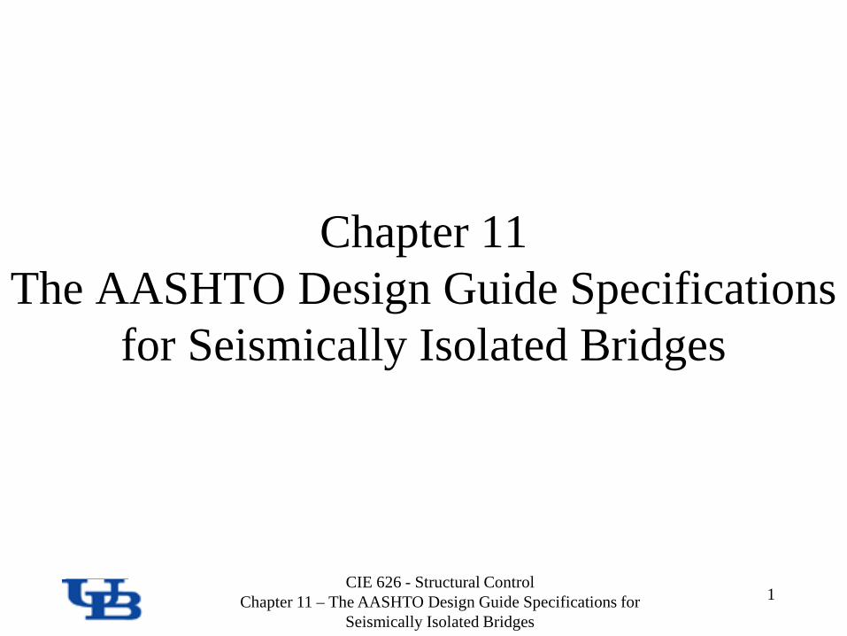
Four possible design methods: 4. Time-history analysis Linear or nonlinear analysis. For linear analysis, the effective stiffness of the isolation
system must correspond to the design displacement. Equivalent force method can be used as starting point. Iterations required.
For nonlinear analysis, the nonlinear behavior of the isolation system must be modeled.
The selection of ground motion time-histories follow the same rules as that of ASCE 7-10 (see Section 3).
10
2. Design Methods

Supplemental Damping and Seismic Isolation Chapter 10 – Seismic Isolation Systems
CIE 626 - Structural Control Chapter 11 – The AASHTO Design Guide
Specifications for Seismically Isolated Bridges
3. Equivalent Static Force Method
. .
11

Supplemental Damping and Seismic Isolation Chapter 10 – Seismic Isolation Systems
CIE 626 - Structural Control Chapter 11 – The AASHTO Design Guide
Specifications for Seismically Isolated Bridges
Teff
3. Equivalent Static Force Method
12

Supplemental Damping and Seismic Isolation Chapter 10 – Seismic Isolation Systems
CIE 626 - Structural Control Chapter 11 – The AASHTO Design Guide
Specifications for Seismically Isolated Bridges
13
3.0
05.0
ζ
0.77 1.00 1.23 1.52 1.71 1.87 2.00
3. Equivalent Static Force Method
13

Supplemental Damping and Seismic Isolation Chapter 10 – Seismic Isolation Systems
CIE 626 - Structural Control Chapter 11 – The AASHTO Design Guide
Specifications for Seismically Isolated Bridges
14
Effective damping coefficient
Must consider all sources of damping Isolation system + parallel dampers
14
effζ
3. Equivalent Static Force Method

Supplemental Damping and Seismic Isolation Chapter 10 – Seismic Isolation Systems
CIE 626 - Structural Control Chapter 11 – The AASHTO Design Guide
Specifications for Seismically Isolated Bridges
• Flexibility of sub-structure must be considered in design and analysis of an isolated bridge
3. Equivalent Static Force Method
15

Supplemental Damping and Seismic Isolation Chapter 10 – Seismic Isolation Systems
CIE 626 - Structural Control Chapter 11 – The AASHTO Design Guide
Specifications for Seismically Isolated Bridges
3. Equivalent Static Force Method
16

Supplemental Damping and Seismic Isolation Chapter 10 – Seismic Isolation Systems
CIE 626 - Structural Control Chapter 11 – The AASHTO Design Guide
Specifications for Seismically Isolated Bridges
3. Equivalent Static Force Method
17

Supplemental Damping and Seismic Isolation Chapter 10 – Seismic Isolation Systems
CIE 626 - Structural Control Chapter 11 – The AASHTO Design Guide
Specifications for Seismically Isolated Bridges
• Iterative Design Flow Chart
Assume a deck displacement value, ∆
Determine maximum force in the isolators, V, @ displacement ∆
Compute effective stiffness of the isolators, keff, @ displacement ∆: keff =V/∆
Compute effective period of the isolators, Teff, @ displacement ∆:
Calculate equivalent viscous damping of the isolators, ζ, and determine damping reduction factor BD
Compute updated deck displacement, ∆∗ :
*
? ∆≈ ∆*
Yes No End ∆ = ∆*
Teff
18

Supplemental Damping and Seismic Isolation Chapter 10 – Seismic Isolation Systems
CIE 626 - Structural Control Chapter 11 – The AASHTO Design Guide
Specifications for Seismically Isolated Bridges
4. Design Properties of Seismic Isolation System
• AASHTO guide specifications require bounding analyses: – Determine variations in design forces resulting from minimum and maximum
effective stiffness values and damping of isolation system. • Guidelines define property modification factors:
– Established from characterization tests on prototype isolation bearings. – Consider variations of effective stiffness and damping of isolation system. – Effects considered:
• Temperature; • Aging (including corrosion); • Velocity; • Wear; • Contamination (sliding systems only); and • Scragging (elastomeric systems).
– Proposed values developed by Constantinou et al. (1999). 19

Supplemental Damping and Seismic Isolation Chapter 10 – Seismic Isolation Systems
CIE 626 - Structural Control Chapter 11 – The AASHTO Design Guide
Specifications for Seismically Isolated Bridges
• Concept of Property Modification Factors
4. Design Properties of Seismic Isolation System
20

Supplemental Damping and Seismic Isolation Chapter 10 – Seismic Isolation Systems
CIE 626 - Structural Control Chapter 11 – The AASHTO Design Guide
Specifications for Seismically Isolated Bridges
• Concept of Property Modification Factor
4. Design Properties of Seismic Isolation System
21

Supplemental Damping and Seismic Isolation Chapter 10 – Seismic Isolation Systems
CIE 626 - Structural Control Chapter 11 – The AASHTO Design Guide
Specifications for Seismically Isolated Bridges
• Property Modification Factors for Coefficient of Friction of Sliding Bearings
4. Design Properties of Seismic Isolation System
22

Supplemental Damping and Seismic Isolation Chapter 10 – Seismic Isolation Systems
CIE 626 - Structural Control Chapter 11 – The AASHTO Design Guide
Specifications for Seismically Isolated Bridges
• Property Modification Factors for Coefficient of Friction of Sliding Bearings
4. Design Properties of Seismic Isolation System
23

Supplemental Damping and Seismic Isolation Chapter 10 – Seismic Isolation Systems
CIE 626 - Structural Control Chapter 11 – The AASHTO Design Guide
Specifications for Seismically Isolated Bridges
• Property Modification Factors for Coefficient of Friction of Sliding Bearings
Un
4. Design Properties of Seismic Isolation System
24

Supplemental Damping and Seismic Isolation Chapter 10 – Seismic Isolation Systems
CIE 626 - Structural Control Chapter 11 – The AASHTO Design Guide
Specifications for Seismically Isolated Bridges
• Property Modification Factors for Coefficient of Friction of Sliding Bearings
4. Design Properties of Seismic Isolation System
25

Supplemental Damping and Seismic Isolation Chapter 10 – Seismic Isolation Systems
CIE 626 - Structural Control Chapter 11 – The AASHTO Design Guide
Specifications for Seismically Isolated Bridges
• Property Modification Factors for Coefficient of Friction of Sliding Bearings
4. Design Properties of Seismic Isolation System
26

Supplemental Damping and Seismic Isolation Chapter 10 – Seismic Isolation Systems
CIE 626 - Structural Control Chapter 11 – The AASHTO Design Guide
Specifications for Seismically Isolated Bridges
• Property Modification Factors for Elastomeric Bearings
4. Design Properties of Seismic Isolation System
27

Supplemental Damping and Seismic Isolation Chapter 10 – Seismic Isolation Systems
CIE 626 - Structural Control Chapter 11 – The AASHTO Design Guide
Specifications for Seismically Isolated Bridges
• Property Modification Factors for Elastomeric Bearings
4. Design Properties of Seismic Isolation System
28

Supplemental Damping and Seismic Isolation Chapter 10 – Seismic Isolation Systems
CIE 626 - Structural Control Chapter 11 – The AASHTO Design Guide
Specifications for Seismically Isolated Bridges
• Property Modification Factors for Elastomeric Bearings
LDRB: Low Damping Rubber Bearings HDRB: High Damping Rubber Bearings
4. Design Properties of Seismic Isolation System
29

Supplemental Damping and Seismic Isolation Chapter 10 – Seismic Isolation Systems
CIE 626 - Structural Control Chapter 11 – The AASHTO Design Guide
Specifications for Seismically Isolated Bridges
• Property Modification Factors for Elastomeric Bearings
4. Design Properties of Seismic Isolation System
30

Supplemental Damping and Seismic Isolation Chapter 10 – Seismic Isolation Systems
CIE 626 - Structural Control Chapter 11 – The AASHTO Design Guide
Specifications for Seismically Isolated Bridges
• Property Modification Factors for Elastomeric Bearings
-150
-120
-90
-60
-30
0
30
60
90
120
150
-120 -90 -60 -30 0 30 60 90 120
Displacement (mm)
Later
al Fo
rce (
kN)
Lead-rubber Bearing-26oC for 48 hrsvel.=250mm/sVertical Load = 1100kN
-150
-120
-90
-60
-30
0
30
60
90
120
150
-120 -90 -60 -30 0 30 60 90 120
Displacement (mm)
Later
al Fo
rce (
kN)
Lead-rubber Bearing20oC, vel.=250mm/sVertical Load = 1100kN
LEAD-RUBBER BEARING, UNIVERSITY AT BUFFALO LOAD=1100kN, DISPLACEMENT=100mm, VELOCITY=250mm/sec
TEMP=20OC
TEMP=-25OC
Courtesy of M. Constantinou
4. Design Properties of Seismic Isolation System
31

Supplemental Damping and Seismic Isolation Chapter 10 – Seismic Isolation Systems
CIE 626 - Structural Control Chapter 11 – The AASHTO Design Guide
Specifications for Seismically Isolated Bridges
5. Minimum Clearances • The clearance between the bridge deck and any
surrounding structure in each principal direction must be at least equal to the total maximum. displacement of the deck obtained from analysis.
• However, the clearance cannot be less than 80% of the total maximum displacement obtained from the equivalent static force procedure.
32

Supplemental Damping and Seismic Isolation Chapter 10 – Seismic Isolation Systems
CIE 626 - Structural Control Chapter 11 – The AASHTO Design Guide
Specifications for Seismically Isolated Bridges
6. Required Testing Program for Isolation Bearings
• AASHTO guide specifications require that all isolation systems have design properties and seismic performance verified by testing.
• Three different types of tests: – i) System characterization tests; – ii) Prototype tests; and – iii) Quality control tests.
• If seismic isolation system has undergone similar testing program, not need to be re-tested, design properties based on pre-approved certified test data from manufacturer of isolation system.
33

Supplemental Damping and Seismic Isolation Chapter 10 – Seismic Isolation Systems
CIE 626 - Structural Control Chapter 11 – The AASHTO Design Guide
Specifications for Seismically Isolated Bridges
34
I. System characterization tests Cyclic tests on individual isolators according to nationally recognized standards (e.g. HITEC,
2002; NIST, 1996). Shake table tests on isolated bridge models with a scale factor of at least 1:4. Low temperature tests
For cold regions applications. Stability tests at temperatures of -7oC to -26oC depending on the temperature application zone given by the
AASHTO Bridge Design Standard. One static loading cycle at the displacement caused by the gravity load given below plus 1.1 times the
maximum total MCE displacement (return period of 1000 years). Gravity load equals to 1.2 times the dead load plus 1.0 time the live load and all the non-seismic load
causing a rotation of the isolators. Wear and fatigue tests
Thermal and rotational displacements corresponding to 30 years of service. Minimum cumulative displacements:
Isolators with dampers connected at the neutral axis of the beams: 1.6 km (1 mile) Isolators with dampers connected to the inferior portion of the bridge deck: 3.2 km (2 miles)
For cold regions applications, the tests must be conducted at temperatures of -7oC to -26oC depending on the temperature application zone given by the AASHTO Bridge Design Standard.
34
6. Required Testing Program for Isolation Bearings

Supplemental Damping and Seismic Isolation Chapter 10 – Seismic Isolation Systems
CIE 626 - Structural Control Chapter 11 – The AASHTO Design Guide
Specifications for Seismically Isolated Bridges
35
II. Prototype tests On at least two full-scale isolators. Tests on reduced scale isolators can be performed only if the capacities of the existing testing machines are not sufficient. Requires a special
permission from the engineer of record. Isolators successfully tested can be used in construction. Thermal tests
Three reversed cycles at the anticipated thermal displacement. Loading rate must be at least 0.076 mm/min.
Wind and breaking tests 20 reversed cycles at he anticipated wind and breaking displacements. Total duration of each test must be at least 40 seconds. Following the cyclic tests, the total load must be maintained for 1 minute.
Seismic tests Three reverse cycles for the following sequence of multiples of the maximum total design displacement (pier + isolator): 1.0, 0.25, 0.50, 0.75, 1.0
and 1.25. Post-seismic wind and breaking tests
Similar to the pre-seismic wind and breaking tests described above. Seismic performance tests
Three reverse cycles at the maximum total design displacement (pier + isolator). For bi-directional isolators, the tests must be conducted in the orthogonal direction of the seismic tests described above.
Stability tests One static loading cycle at the displacement caused by the gravity load as defined below plus 1.1 time the maximum total MCE displacement (return
period of 1000 years). Gravity load equals to 1.2 times the dead load plus 1.0 time the live load and all the non-seismic load causing a rotation of the isolators.
35
6. Required Testing Program for Isolation Bearings

Supplemental Damping and Seismic Isolation Chapter 10 – Seismic Isolation Systems
CIE 626 - Structural Control Chapter 11 – The AASHTO Design Guide
Specifications for Seismically Isolated Bridges
36
III. Quality control tests Compression tests
Five minutes at a compression load equals to 1.5 times the maximum anticipated gravity load (dead plus live load).
Compression and shear tests Two isolators can be tested simultaneously. Three reversed cycles at the total maximum displacement (pier + isolator) or at 50% of the
total rubber thickness (for rubber bearings). Average compressions dead load. Average effective stiffness (Keff) and energy dissipated per cycle (EDC) must not deviate
more than the values tabulated below.
Keff EDC
Each bearing ± 20% -25%
Average of the group ± 10% -15%
36
6. Required Testing Program for Isolation Bearings

Supplemental Damping and Seismic Isolation Chapter 10 – Seismic Isolation Systems
CIE 626 - Structural Control Chapter 11 – The AASHTO Design Guide
Specifications for Seismically Isolated Bridges
• See Chapter 9
http://mceer.buffalo.edu/publications/catalog/reports/LRFD-Based-Analysis-and-Design-Procedures-for-Bridge-Bearings-and-Seismic-Isolators-MCEER-11-0004.html
7. Adequacy Assessment of Bearings
37

Supplemental Damping and Seismic Isolation Chapter 10 – Seismic Isolation Systems
CIE 626 - Structural Control Chapter 11 – The AASHTO Design Guide
Specifications for Seismically Isolated Bridges
38
Questions/Discussions