Embed Size (px)
Citation preview
PROPRIETARY MATERIAL. © 2007 The McGraw-Hill Companies, Inc. All rights reserved. No part of this Manual may be displayed, reproduced or distributed in any form or by any means, without the prior written permission of the publisher, or used beyond the limited distribution to teachers and educators permitted by McGraw-Hill for their individual course preparation. If you are a student using this Manual, you are using it without permission.
Chapter 12, Problem 1. If Vab = 400 V in a balanced Y-connected three-phase generator, find the phase voltages, assuming the phase sequence is: (a) abc (b) acb Chapter 12, Solution 1.
(a) If 400ab =V , then
=°∠= 30-3
400anV V30-231 °∠
=bnV V150-231 °∠ =cnV V270-231 °∠
(b) For the acb sequence,
°∠−°∠=−= 120V0V ppbnanab VVV
°∠=⎟⎟⎠
⎞⎜⎜⎝
⎛−+= 30-3V
23
j21
1V ppabV
i.e. in the acb sequence, abV lags anV by 30°. Hence, if 400ab =V , then
=°∠= 303
400anV V30231 °∠
=bnV V150231 °∠ =cnV V90-231 °∠
Chapter 12, Problem 2. What is the phase sequence of a balanced three-phase circuit for which Van = 160 °∠30 V and Vcn = 160 °−∠ 90 V? Find Vbn. Chapter 12, Solution 2. Since phase c lags phase a by 120°, this is an acb sequence.
=°+°∠= )120(30160bnV V150160 °∠
PROPRIETARY MATERIAL. © 2007 The McGraw-Hill Companies, Inc. All rights reserved. No part of this Manual may be displayed, reproduced or distributed in any form or by any means, without the prior written permission of the publisher, or used beyond the limited distribution to teachers and educators permitted by McGraw-Hill for their individual course preparation. If you are a student using this Manual, you are using it without permission.
Chapter 12, Problem 3. Determine the phase sequence of a balanced three-phase circuit in which Vbn = 208 °∠130 V and Vcn = 208 °∠10 V. Obtain Van . Chapter 12, Solution 3. Since bnV leads cnV by 120°, this is an abc sequence.
=°+°∠= )120(130208anV V250208 °∠ Chapter 12, Problem 4. A three-phase system with abc sequence and VL = 200 V feeds a Y-connected load with ZL = 40 Ω°∠30 . Find the line currents.
Chapter 12, Solution 4. 200200 3
3L p pV V V= = ⎯⎯→ =
200 0 2.887 30 A3 40 30
ooan
a oY
VIZ x
<= = = < −
<
120 2.887 150 Ao ob aI I= < − = < −
120 2.887 90 Ao oc aI I= < + = <
Chapter 12, Problem 5. For a Y-connected load, the time-domain expressions for three line-to-neutral voltages at the terminals are: vAN = 150 cos (ω t + 32º) V vBN = 150 cos (ω t – 88º) V vCN = 150 cos (ω t + 152º) V Write the time-domain expressions for the line-to-line voltages vAN, vBC, and vCA . Chapter 12, Solution 5.
3 30 3 150 32 30 260 62o o o oAB pV V x= < = < + = <
Thus, 260cos( 62 ) Vo
ABv tω= + Using abc sequence, 260cos( 58 ) Vo
BCv tω= −
260cos( 182 ) VoCAv tω= +
PROPRIETARY MATERIAL. © 2007 The McGraw-Hill Companies, Inc. All rights reserved. No part of this Manual may be displayed, reproduced or distributed in any form or by any means, without the prior written permission of the publisher, or used beyond the limited distribution to teachers and educators permitted by McGraw-Hill for their individual course preparation. If you are a student using this Manual, you are using it without permission.
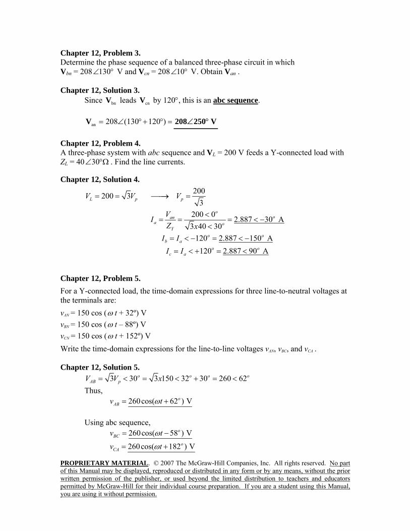
Chapter 12, Problem 6. For the Y-Y circuit of Fig. 12.41, find the line currents, the line voltages, and the load voltages.
Figure 12.41 For Prob. 12.6. Chapter 12, Solution 6.
°∠=+= 26.5618.115j10YZ The line currents are
=°∠
°∠==
26.5618.110220
Y
ana Z
VI A26.56-68.19 °∠
=°∠= 120-ab II A146.56-68.19 °∠ =°∠= 120ac II A93.4468.19 °∠
The line voltages are
=°∠= 303220abV V30381 °∠ =bcV V90-381 °∠ =caV V210-381 °∠
The load voltages are
=== anYaAN VZIV V0220 °∠ == bnBN VV V120-220 °∠ == cnCN VV V120220 °∠
PROPRIETARY MATERIAL. © 2007 The McGraw-Hill Companies, Inc. All rights reserved. No part of this Manual may be displayed, reproduced or distributed in any form or by any means, without the prior written permission of the publisher, or used beyond the limited distribution to teachers and educators permitted by McGraw-Hill for their individual course preparation. If you are a student using this Manual, you are using it without permission.
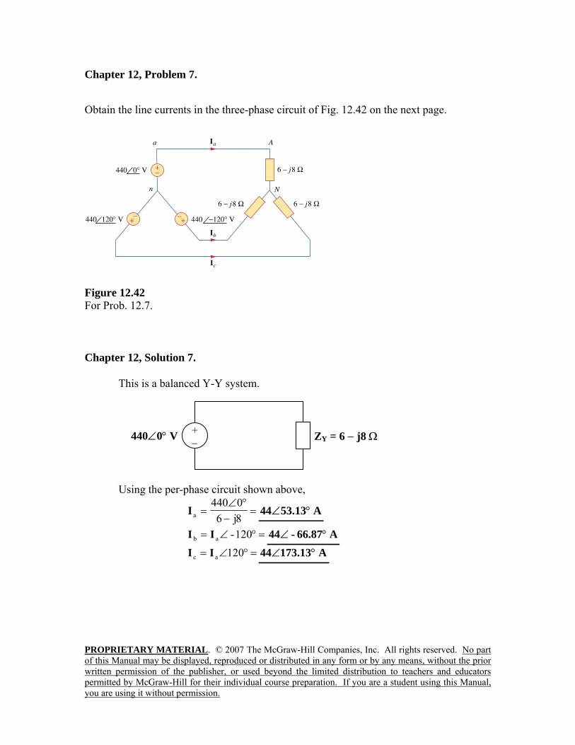
Chapter 12, Problem 7. Obtain the line currents in the three-phase circuit of Fig. 12.42 on the next page.
Figure 12.42 For Prob. 12.7. Chapter 12, Solution 7. This is a balanced Y-Y system.
Using the per-phase circuit shown above,
=−
°∠=
8j60440
aI A53.1344 °∠
=°∠= 120-ab II A66.87-44 °∠ =°∠= 120ac II A13.73144 °∠
440∠0° V + − ZY = 6 − j8 Ω
PROPRIETARY MATERIAL. © 2007 The McGraw-Hill Companies, Inc. All rights reserved. No part of this Manual may be displayed, reproduced or distributed in any form or by any means, without the prior written permission of the publisher, or used beyond the limited distribution to teachers and educators permitted by McGraw-Hill for their individual course preparation. If you are a student using this Manual, you are using it without permission.
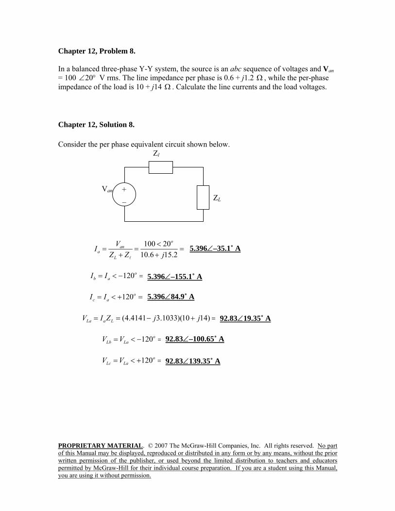
Chapter 12, Problem 8. In a balanced three-phase Y-Y system, the source is an abc sequence of voltages and Van = 100 °∠20 V rms. The line impedance per phase is 0.6 + j1.2 Ω , while the per-phase impedance of the load is 10 + j14 Ω . Calculate the line currents and the load voltages.
Chapter 12, Solution 8. Consider the per phase equivalent circuit shown below. Zl Van ZL
100 20 5.3958 35.1 A10.6 15.2
ooan
aL
VIZ Z j
<= = = < −
+ +l
120 5.3958 155.1 Ao o
b aI I= < − = < − 120 5.3958 84.9 Ao o
c aI I= < + = <
(4.4141 3.1033)(10 14) 92.83 19.35 VoLa a LV I Z j j= = − + = <
120 92.83 100.65 Vo o
Lb LaV V= < − = < − 120 92.83 139.35 Vo o
Lc LaV V= < + = <
+ _
5.396∠–35.1˚ A
5.396∠–155.1˚ A
5.396∠84.9˚ A
92.83∠19.35˚ A
92.83∠–100.65˚ A
92.83∠139.35˚ A
PROPRIETARY MATERIAL. © 2007 The McGraw-Hill Companies, Inc. All rights reserved. No part of this Manual may be displayed, reproduced or distributed in any form or by any means, without the prior written permission of the publisher, or used beyond the limited distribution to teachers and educators permitted by McGraw-Hill for their individual course preparation. If you are a student using this Manual, you are using it without permission.
Chapter 12, Problem 9. A balanced Y-Y four-wire system has phase voltages
°∠= 0120anV °−∠= 120120bnV
V 120120 °∠=cnV
The load impedance per phase is 19 + j13 Ω , and the line impedance per phase is 1 + j2 Ω . Solve for the line currents and neutral current. Chapter 12, Solution 9.
=+
°∠=
+=
15j200120
YL
ana ZZ
VI A36.87-8.4 °∠
=°∠= 120-ab II A156.87-8.4 °∠
=°∠= 120ac II A83.138.4 °∠
As a balanced system, =nI A0
PROPRIETARY MATERIAL. © 2007 The McGraw-Hill Companies, Inc. All rights reserved. No part of this Manual may be displayed, reproduced or distributed in any form or by any means, without the prior written permission of the publisher, or used beyond the limited distribution to teachers and educators permitted by McGraw-Hill for their individual course preparation. If you are a student using this Manual, you are using it without permission.
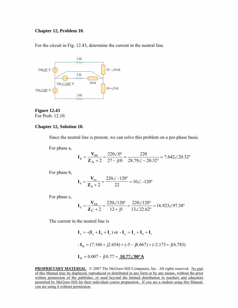
Chapter 12, Problem 10. For the circuit in Fig. 12.43, determine the current in the neutral line.
Figure 12.43 For Prob. 12.10. Chapter 12, Solution 10. Since the neutral line is present, we can solve this problem on a per-phase basis.
For phase a,
°∠=°−∠
=−
°∠=
+= 20.32642.7
32.2079.28220
10j270220
2A
ana Z
VI
For phase b,
°∠=°∠
=+
= 120-1022
120-2202B
bnb Z
VI
For phase c,
°∠=°∠°∠
=+
°∠=
+= 97.38923.16
62.2213120220
5j12120220
2C
cnc Z
VI
The current in the neutral line is
)-( cban IIII ++= or cban- IIII ++=
)783.16j173.2-()667.8j5-()654.2j166.7(- n ++−++=I
=−= 77.10j007.0nI 10.77∠90°A
PROPRIETARY MATERIAL. © 2007 The McGraw-Hill Companies, Inc. All rights reserved. No part of this Manual may be displayed, reproduced or distributed in any form or by any means, without the prior written permission of the publisher, or used beyond the limited distribution to teachers and educators permitted by McGraw-Hill for their individual course preparation. If you are a student using this Manual, you are using it without permission.
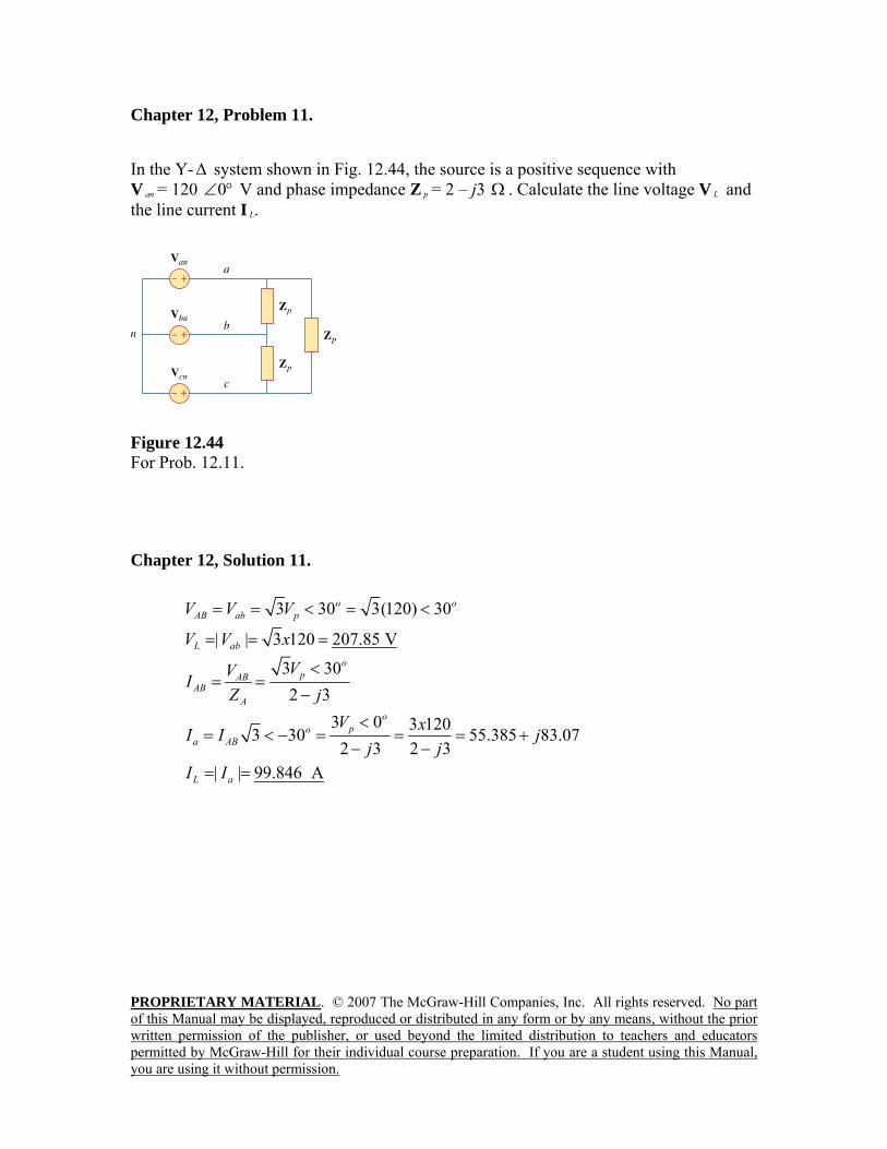
Chapter 12, Problem 11. In the Y-∆ system shown in Fig. 12.44, the source is a positive sequence with V an = 120 °∠0 V and phase impedance Z p = 2 – j3 Ω . Calculate the line voltage V L and the line current I L.
Figure 12.44 For Prob. 12.11.
Chapter 12, Solution 11.
3 30 3(120) 30o oAB ab pV V V= = < = <
| | 3 120 207.85 VL abV V x= = =
3 302 3
opAB
ABA
VVIZ j
<= =
−
3 0 3 1203 30 55.385 83.072 3 2 3
opo
a AB
V xI I jj j<
= < − = = = +− −
| | 99.846 AL aI I= =
PROPRIETARY MATERIAL. © 2007 The McGraw-Hill Companies, Inc. All rights reserved. No part of this Manual may be displayed, reproduced or distributed in any form or by any means, without the prior written permission of the publisher, or used beyond the limited distribution to teachers and educators permitted by McGraw-Hill for their individual course preparation. If you are a student using this Manual, you are using it without permission.
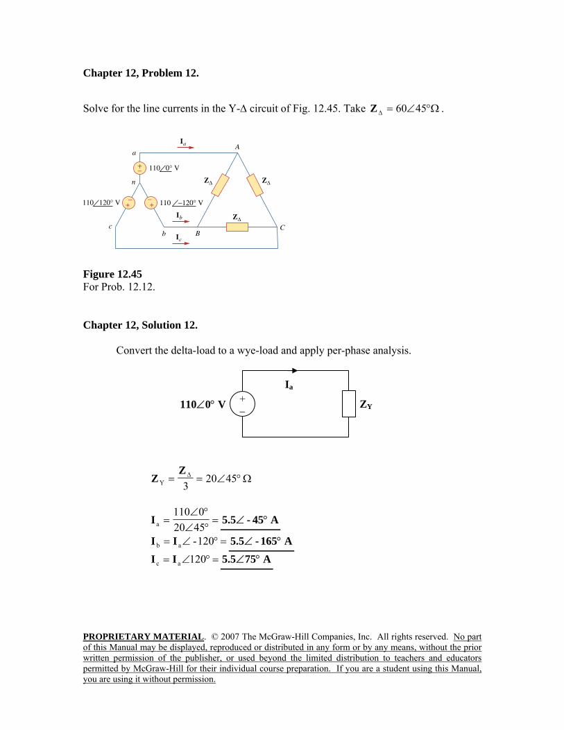
Chapter 12, Problem 12. Solve for the line currents in the Y-∆ circuit of Fig. 12.45. Take Ω°∠=∆ 4560Z .
Figure 12.45 For Prob. 12.12. Chapter 12, Solution 12. Convert the delta-load to a wye-load and apply per-phase analysis.
Ω°∠== ∆ 45203Y
ZZ
=°∠°∠
=45200110
aI A45-5.5 °∠
=°∠= 120-ab II A165-5.5 °∠ =°∠= 120ac II A755.5 °∠
ZY 110∠0° V + −
Ia
PROPRIETARY MATERIAL. © 2007 The McGraw-Hill Companies, Inc. All rights reserved. No part of this Manual may be displayed, reproduced or distributed in any form or by any means, without the prior written permission of the publisher, or used beyond the limited distribution to teachers and educators permitted by McGraw-Hill for their individual course preparation. If you are a student using this Manual, you are using it without permission.
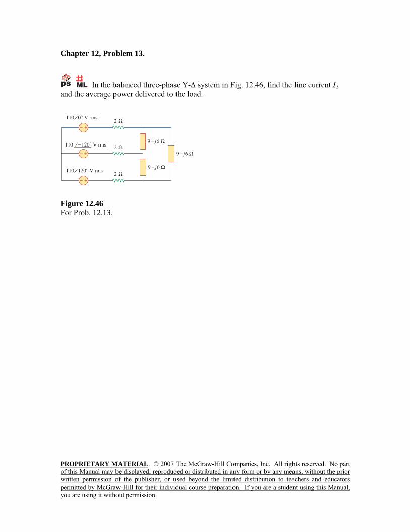
Chapter 12, Problem 13.
In the balanced three-phase Y-∆ system in Fig. 12.46, find the line current I L and the average power delivered to the load.
Figure 12.46 For Prob. 12.13.
PROPRIETARY MATERIAL. © 2007 The McGraw-Hill Companies, Inc. All rights reserved. No part of this Manual may be displayed, reproduced or distributed in any form or by any means, without the prior written permission of the publisher, or used beyond the limited distribution to teachers and educators permitted by McGraw-Hill for their individual course preparation. If you are a student using this Manual, you are using it without permission.
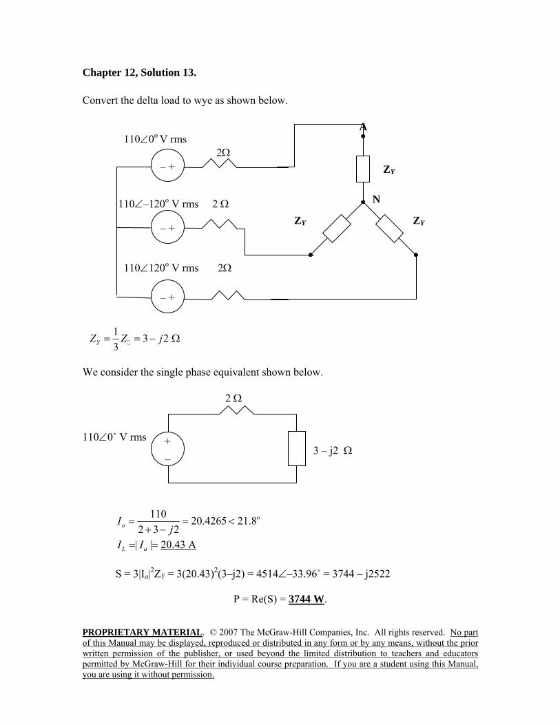
Chapter 12, Solution 13. Convert the delta load to wye as shown below. 110∠0o V rms 2Ω
110∠–120o V rms 2 Ω 110∠120o V rms 2Ω
1 3 2 3YZ Z j= = − Ω
We consider the single phase equivalent shown below. 2 Ω 110∠0˚ V rms 3 – j2 Ω
110 20.4265 21.8
2 3 2o
aIj
= = <+ −
| | 20.43 AL aI I= =
S = 3|Ia|2ZY = 3(20.43)2(3–j2) = 4514∠–33.96˚ = 3744 – j2522
P = Re(S) = 3744 W.
+ _
– +
– +
– +
ZY
A
N
ZY ZY
PROPRIETARY MATERIAL. © 2007 The McGraw-Hill Companies, Inc. All rights reserved. No part of this Manual may be displayed, reproduced or distributed in any form or by any means, without the prior written permission of the publisher, or used beyond the limited distribution to teachers and educators permitted by McGraw-Hill for their individual course preparation. If you are a student using this Manual, you are using it without permission.
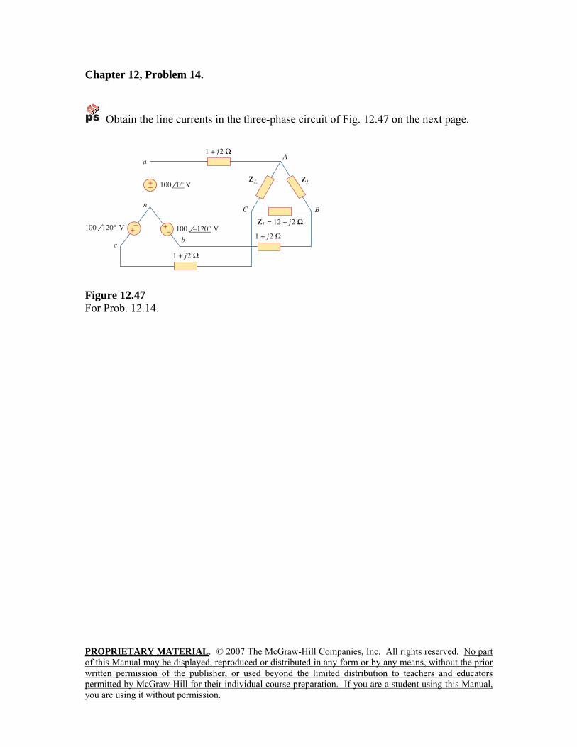
Chapter 12, Problem 14.
Obtain the line currents in the three-phase circuit of Fig. 12.47 on the next page.
100 –120°
Figure 12.47 For Prob. 12.14.
PROPRIETARY MATERIAL. © 2007 The McGraw-Hill Companies, Inc. All rights reserved. No part of this Manual may be displayed, reproduced or distributed in any form or by any means, without the prior written permission of the publisher, or used beyond the limited distribution to teachers and educators permitted by McGraw-Hill for their individual course preparation. If you are a student using this Manual, you are using it without permission.
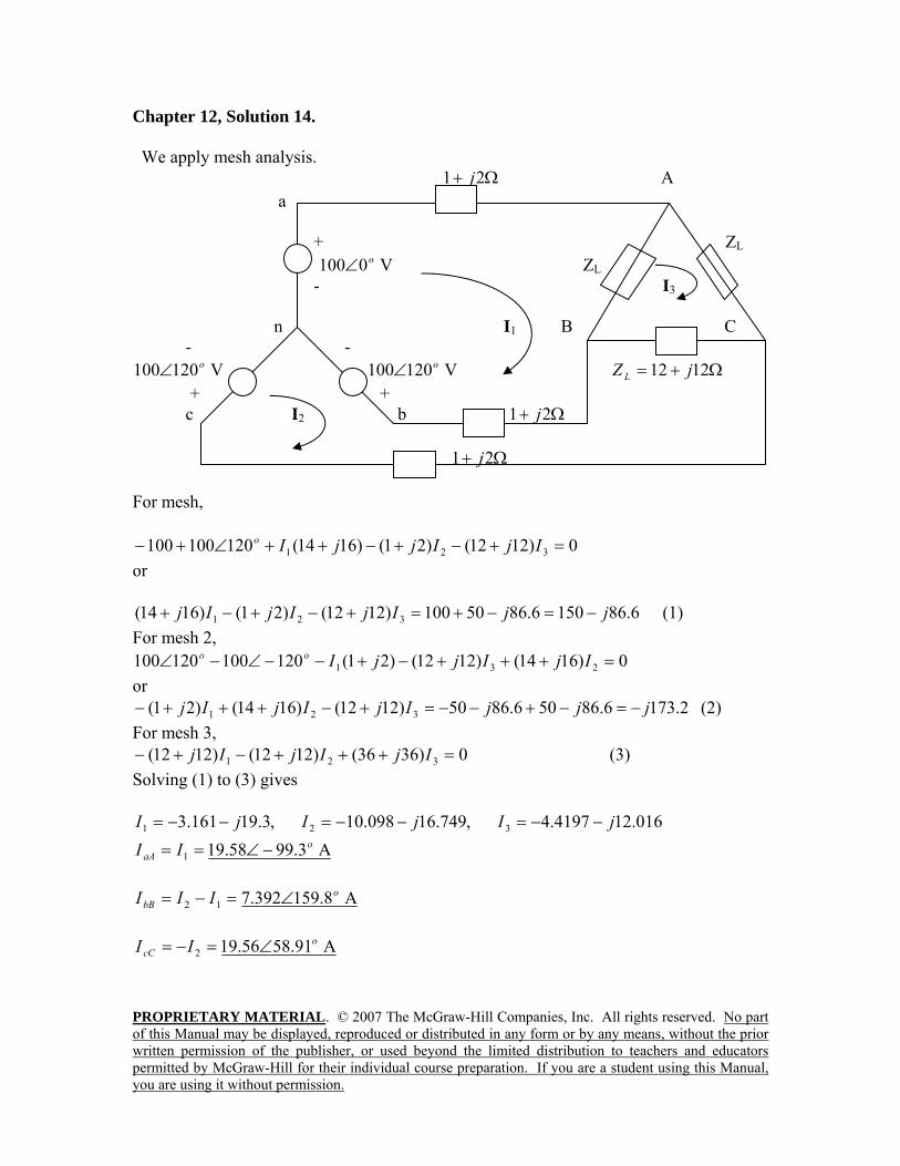
Chapter 12, Solution 14. We apply mesh analysis. Ω+ 21 j A a + ZL V 0100 o∠ ZL - I3 n I1 B C - -
V 120100 o∠ V 120100 o∠ Ω+= 1212 jZ L + - + c I2 b Ω+ 21 j Ω+ 21 j For mesh,
0)1212()21()1614(120100100 321 =+−+−++∠+− IjIjjIo or
6.861506.8650100)1212()21()1614( 321 jjIjIjIj −=−+=+−+−+ (1) For mesh 2,
0)1614()1212()21(120100120100 231 =+++−+−−∠−∠ IjIjjIoo or
2.1736.86506.8650)1212()1614()21( 321 jjjIjIjIj −=−+−−=+−+++− (2) For mesh 3,
0)3636()1212()1212( 321 =+++−+− IjIjIj (3) Solving (1) to (3) gives
016.124197.4,749.16098.10,3.19161.3 321 jIjIjI −−=−−=−−= A 3.9958.191
oaA II −∠==
A 8.159392.712
obB III ∠=−=
A 91.5856.192
ocC II ∠=−=
PROPRIETARY MATERIAL. © 2007 The McGraw-Hill Companies, Inc. All rights reserved. No part of this Manual may be displayed, reproduced or distributed in any form or by any means, without the prior written permission of the publisher, or used beyond the limited distribution to teachers and educators permitted by McGraw-Hill for their individual course preparation. If you are a student using this Manual, you are using it without permission.
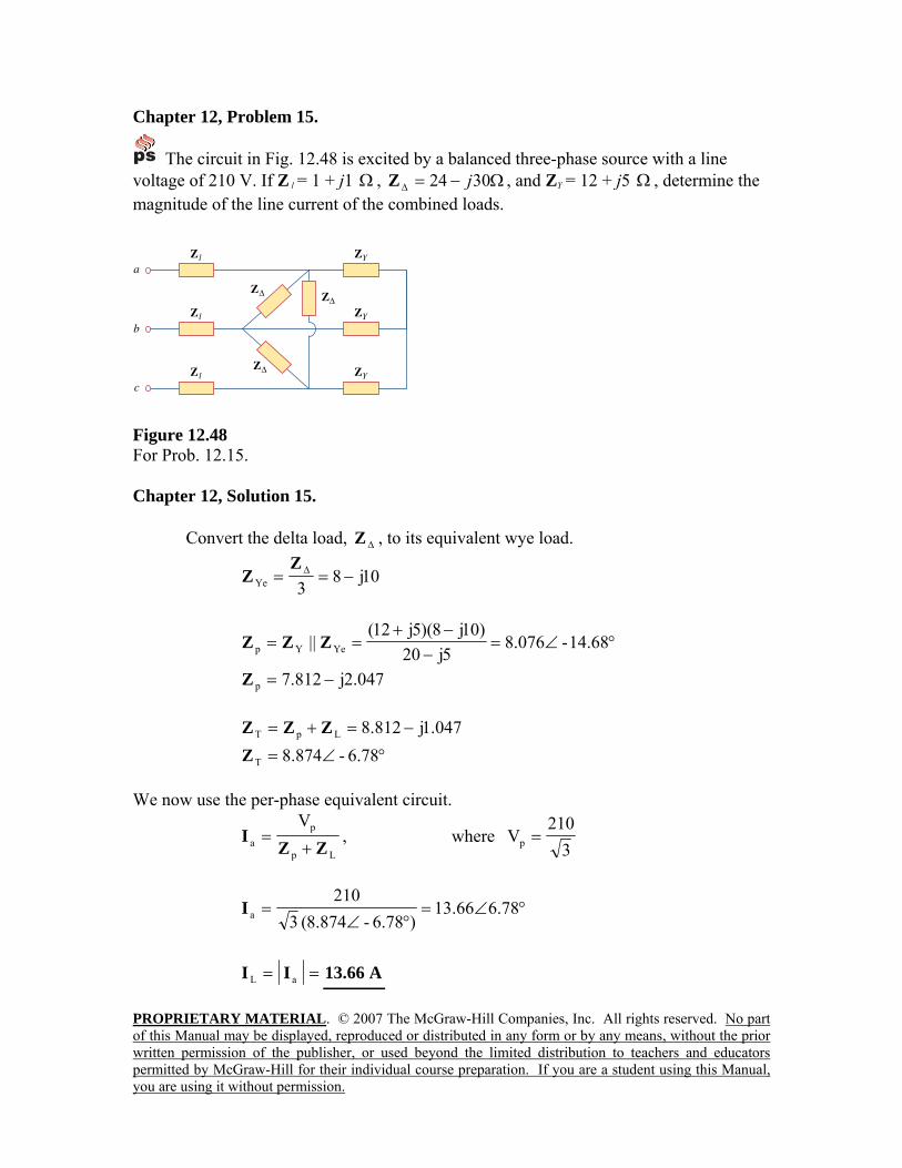
Chapter 12, Problem 15.
The circuit in Fig. 12.48 is excited by a balanced three-phase source with a line voltage of 210 V. If Z l = 1 + j1 Ω , Ω−=∆ 3024 jZ , and ZY = 12 + j5 Ω , determine the magnitude of the line current of the combined loads.
Figure 12.48 For Prob. 12.15. Chapter 12, Solution 15. Convert the delta load, ∆Z , to its equivalent wye load.
10j83Ye −== ∆Z
Z
°∠=−
−+== 14.68-076.8
5j20)10j8)(5j12(
|| YeYp ZZZ
047.2j812.7p −=Z
047.1j812.8LpT −=+= ZZZ °∠= 6.78-874.8TZ
We now use the per-phase equivalent circuit.
Lp
pa
VZZ
I+
= , where 3
210Vp =
°∠=°∠
= 78.666.13)6.78-874.8(3
210aI
== aL II A66.13
PROPRIETARY MATERIAL. © 2007 The McGraw-Hill Companies, Inc. All rights reserved. No part of this Manual may be displayed, reproduced or distributed in any form or by any means, without the prior written permission of the publisher, or used beyond the limited distribution to teachers and educators permitted by McGraw-Hill for their individual course preparation. If you are a student using this Manual, you are using it without permission.
Chapter 12, Problem 16. A balanced delta-connected load has a phase current I AC = 10 °−∠ 30 A. (a) Determine the three line currents assuming that the circuit operates in the positive phase sequence. (b) Calculate the load impedance if the line voltage is V AB = 110 °∠0 V. Chapter 12, Solution 16.
(a) °∠=°+°∠== 15010)180-30(10- ACCA II This implies that °∠= 3010ABI
°∠= 90-10BCI
=°∠= 30-3ABa II A032.17 °∠ =bI A120-32.17 °∠ =cI A12032.17 °∠
(b) =°∠°∠
==∆ 30100110
AB
AB
IV
Z Ω°∠ 30-11
Chapter 12, Problem 17. A balanced delta-connected load has line current I a = 10 °−∠ 25 A. Find the phase currents I AB , I BC , and I CA.
Chapter 12, Solution 17.
103 30 25 30 5.773 5 A3 30 3
o o o oaa AB AB o
II I I= < − ⎯⎯→ = = < − + = << −
120 5.775 115 Ao oBC ABI I= < − = < −
120 5.775 125 Ao oCA ABI I= < + = <
PROPRIETARY MATERIAL. © 2007 The McGraw-Hill Companies, Inc. All rights reserved. No part of this Manual may be displayed, reproduced or distributed in any form or by any means, without the prior written permission of the publisher, or used beyond the limited distribution to teachers and educators permitted by McGraw-Hill for their individual course preparation. If you are a student using this Manual, you are using it without permission.
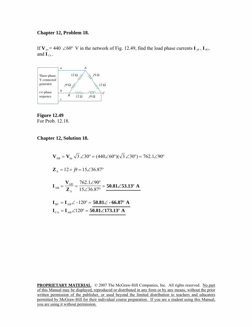
Chapter 12, Problem 18. If V an = 440 °∠60 V in the network of Fig. 12.49, find the load phase currents I AB , I BC, and I CA .
Figure 12.49 For Prob. 12.18. Chapter 12, Solution 18.
°∠=°∠°∠=°∠= 901.762)303)(60440(303anAB VV
°∠=+=∆ 36.87159j12Z
=°∠°∠
==∆ 36.8715
901.762ABAB Z
VI A53.1381.50 °∠
=°∠= 120-ABBC II A66.87-81.50 °∠
=°∠= 120ABCA II A173.1381.50 °∠
PROPRIETARY MATERIAL. © 2007 The McGraw-Hill Companies, Inc. All rights reserved. No part of this Manual may be displayed, reproduced or distributed in any form or by any means, without the prior written permission of the publisher, or used beyond the limited distribution to teachers and educators permitted by McGraw-Hill for their individual course preparation. If you are a student using this Manual, you are using it without permission.
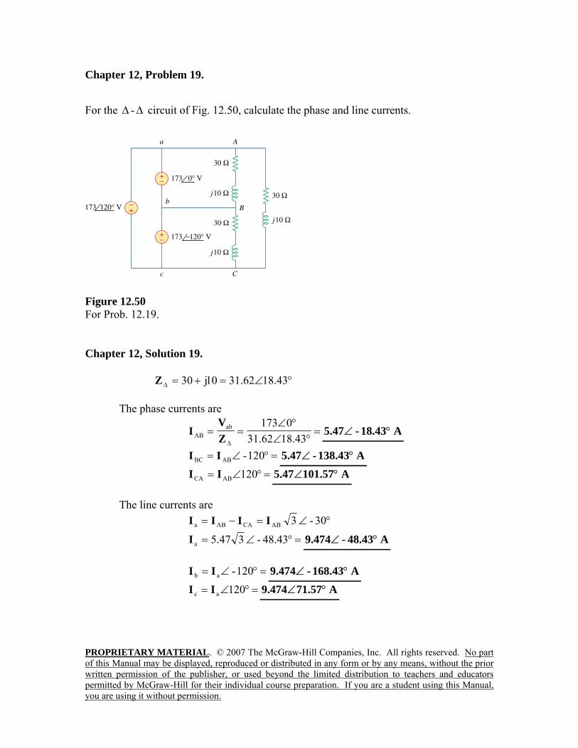
Chapter 12, Problem 19. For the ∆ -∆ circuit of Fig. 12.50, calculate the phase and line currents.
Figure 12.50 For Prob. 12.19. Chapter 12, Solution 19.
°∠=+=∆ 18.4362.3110j30Z The phase currents are
=°∠
°∠==
∆ 18.4362.310173ab
AB ZV
I A18.43-47.5 °∠
=°∠= 120-ABBC II A138.43-47.5 °∠ =°∠= 120ABCA II A101.5747.5 °∠
The line currents are
°∠=−= 30-3ABCAABa IIII
=°∠= 48.43-347.5aI A48.43-474.9 °∠
=°∠= 120-ab II A168.43-474.9 °∠ =°∠= 120ac II A71.57474.9 °∠
PROPRIETARY MATERIAL. © 2007 The McGraw-Hill Companies, Inc. All rights reserved. No part of this Manual may be displayed, reproduced or distributed in any form or by any means, without the prior written permission of the publisher, or used beyond the limited distribution to teachers and educators permitted by McGraw-Hill for their individual course preparation. If you are a student using this Manual, you are using it without permission.
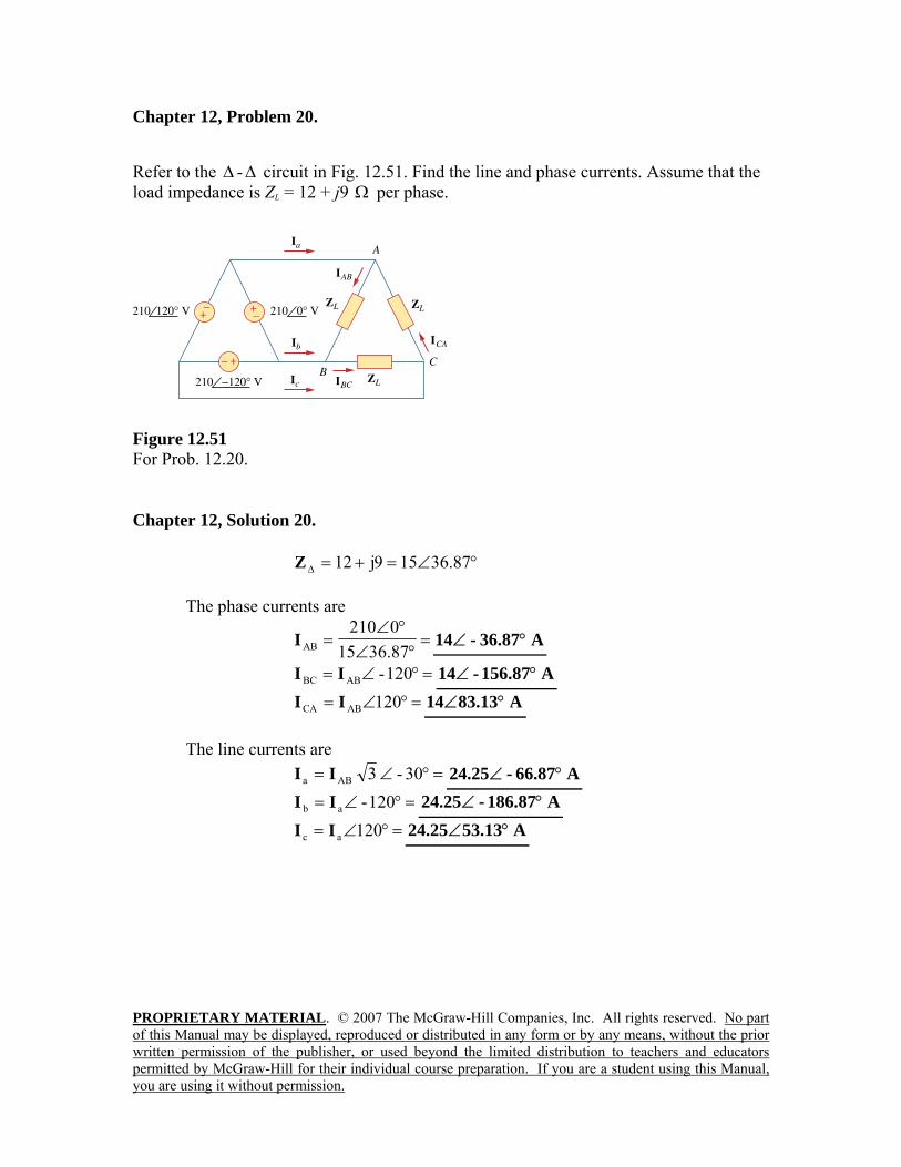
Chapter 12, Problem 20. Refer to the ∆ -∆ circuit in Fig. 12.51. Find the line and phase currents. Assume that the load impedance is ZL = 12 + j9 Ω per phase.
Figure 12.51 For Prob. 12.20. Chapter 12, Solution 20.
°∠=+=∆ 36.87159j12Z The phase currents are
=°∠
°∠=
36.87150210
ABI A36.87-14 °∠
=°∠= 120-ABBC II A156.87-14 °∠ =°∠= 120ABCA II A83.1314 °∠
The line currents are
=°∠= 30-3ABa II A66.87-25.24 °∠ =°∠= 120-ab II A186.87-25.24 °∠
=°∠= 120ac II A53.1325.24 °∠
PROPRIETARY MATERIAL. © 2007 The McGraw-Hill Companies, Inc. All rights reserved. No part of this Manual may be displayed, reproduced or distributed in any form or by any means, without the prior written permission of the publisher, or used beyond the limited distribution to teachers and educators permitted by McGraw-Hill for their individual course preparation. If you are a student using this Manual, you are using it without permission.
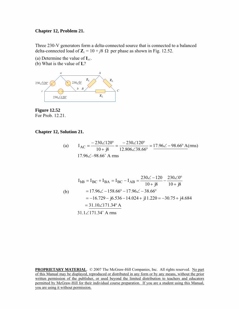
Chapter 12, Problem 21. Three 230-V generators form a delta-connected source that is connected to a balanced delta-connected load of ZL = 10 + j8 Ω per phase as shown in Fig. 12.52. (a) Determine the value of IAC. (b) What is the value of Ib?
Figure 12.52 For Prob. 12.21. Chapter 12, Solution 21.
(a) )rms(A66.9896.1766.38806.12
1202308j10
120230IAC °−∠=°∠
°∠−=
+°∠−
=
17.96∠–98.66˚ A rms
(b)
A34.17110.31684.4j75.30220.11j024.14536.6j729.16
66.3896.1766.15896.178j100230
8j10120230IIIII ABBCBABCbB
°∠=+−=+−−−=
°−∠−°−∠=+
°∠−
+−∠
=−=+=
31.1∠171.34˚ A rms
PROPRIETARY MATERIAL. © 2007 The McGraw-Hill Companies, Inc. All rights reserved. No part of this Manual may be displayed, reproduced or distributed in any form or by any means, without the prior written permission of the publisher, or used beyond the limited distribution to teachers and educators permitted by McGraw-Hill for their individual course preparation. If you are a student using this Manual, you are using it without permission.
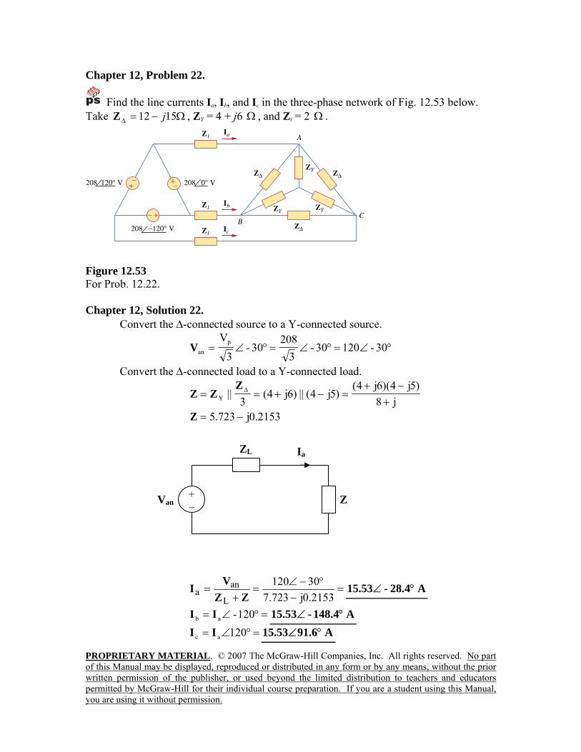
Chapter 12, Problem 22.
Find the line currents Ia, Ib, and Ic in the three-phase network of Fig. 12.53 below. Take Ω−=∆ 1512 jZ , ZY = 4 + j6 Ω , and Zl = 2 Ω .
208 0° V
Figure 12.53 For Prob. 12.22. Chapter 12, Solution 22. Convert the ∆-connected source to a Y-connected source.
°∠=°∠=°∠= 30-12030-3
20830-
3
VpanV
Convert the ∆-connected load to a Y-connected load.
j8)5j4)(6j4(
)5j4(||)6j4(3
||Y +−+
=−+== ∆ZZZ
2153.0j723.5 −=Z
=−
°−∠=
+=
2153.0j723.730120
L
ana ZZ
VI A28.4-53.15 °∠
=°∠= 120-ab II A148.4-53.15 °∠ =°∠= 120ac II A91.653.15 °∠
Z
ZL
+ −
Van
Ia
PROPRIETARY MATERIAL. © 2007 The McGraw-Hill Companies, Inc. All rights reserved. No part of this Manual may be displayed, reproduced or distributed in any form or by any means, without the prior written permission of the publisher, or used beyond the limited distribution to teachers and educators permitted by McGraw-Hill for their individual course preparation. If you are a student using this Manual, you are using it without permission.
Chapter 12, Problem 23. A three-phase balanced system with a line voltage of 202 V rms feeds a delta-connected load with Zp = 25 Ω°∠60 . (a) Find the line current. (b) Determine the total power supplied to the load using two wattmeters connected to the A and C lines. Chapter 12, Solution 23.
(a) oAB
AB6025
202Z
VI
∠==
∆
oo
oo
ABa 90995.136025
303202303II −∠=∠
−∠=−∠=
3.995A1|I|I aL ==
(b)
kW 448.260cos25
3202)202(3cosIV3PPP oLL21 =⎟⎟
⎠
⎞⎜⎜⎝
⎛=θ=+=
PROPRIETARY MATERIAL. © 2007 The McGraw-Hill Companies, Inc. All rights reserved. No part of this Manual may be displayed, reproduced or distributed in any form or by any means, without the prior written permission of the publisher, or used beyond the limited distribution to teachers and educators permitted by McGraw-Hill for their individual course preparation. If you are a student using this Manual, you are using it without permission.
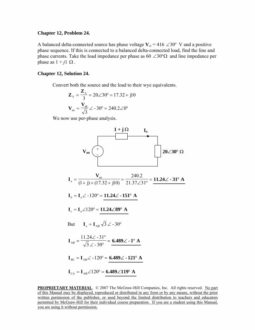
Chapter 12, Problem 24. A balanced delta-connected source has phase voltage Vab = 416 °∠30 V and a positive phase sequence. If this is connected to a balanced delta-connected load, find the line and phase currents. Take the load impedance per phase as 60 Ω°∠30 and line impedance per phase as 1 + j1 Ω . Chapter 12, Solution 24. Convert both the source and the load to their wye equivalents.
10j32.1730203Y +=°∠== ∆Z
Z
°∠=°∠= 02.24030-3ab
an
VV
We now use per-phase analysis.
=°∠
=+++
=3137.212.240
)10j32.17()j1(an
a
VI A31-24.11 °∠
=°∠= 120-ab II A151-24.11 °∠
=°∠= 120ac II A8924.11 °∠
But °∠= 30-3ABa II
=°∠°∠
=30-331-24.11
ABI A1-489.6 °∠
=°∠= 120-ABBC II A121-489.6 °∠
=°∠= 120ABCA II A119489.6 °∠
20∠30° Ω
1 + j Ω
+ −
Van
Ia
PROPRIETARY MATERIAL. © 2007 The McGraw-Hill Companies, Inc. All rights reserved. No part of this Manual may be displayed, reproduced or distributed in any form or by any means, without the prior written permission of the publisher, or used beyond the limited distribution to teachers and educators permitted by McGraw-Hill for their individual course preparation. If you are a student using this Manual, you are using it without permission.
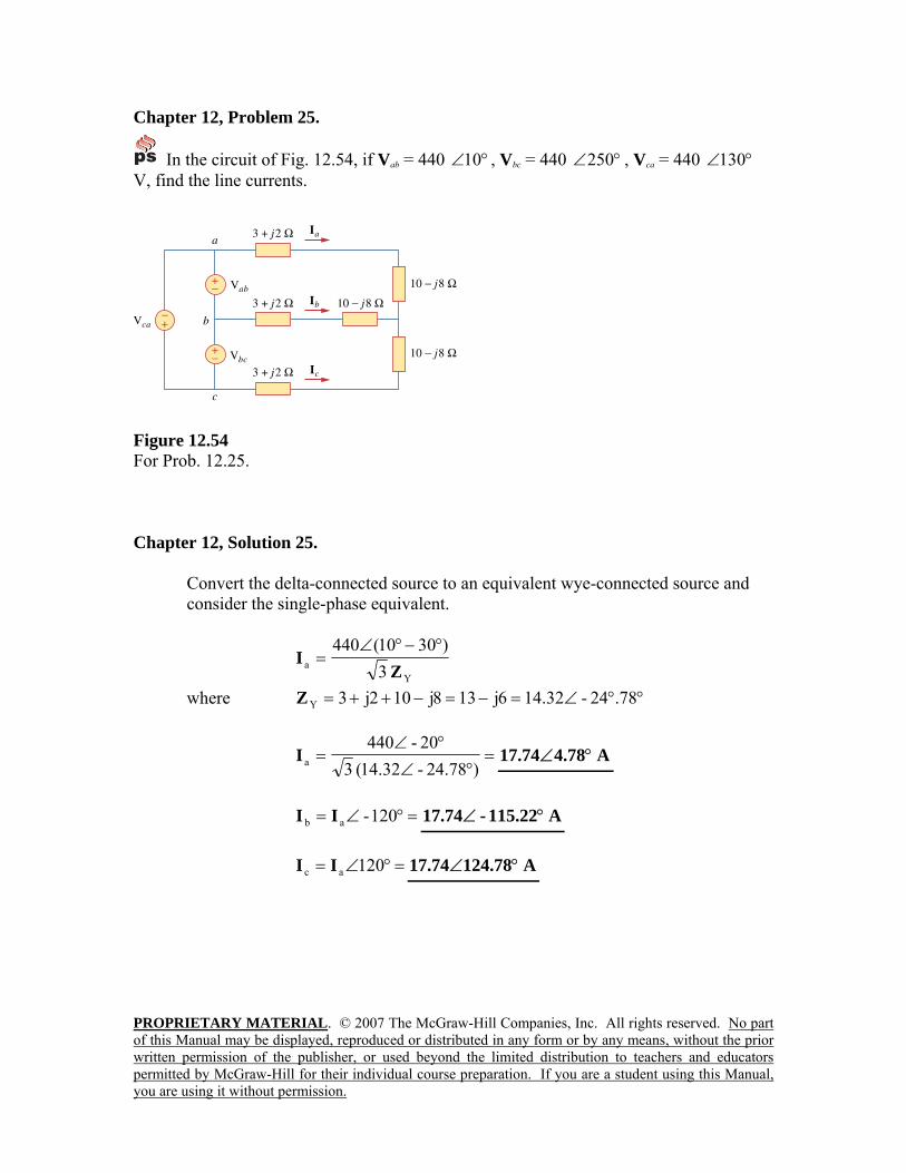
Chapter 12, Problem 25.
In the circuit of Fig. 12.54, if Vab = 440 °∠10 , Vbc = 440 °∠250 , Vca = 440 °∠130 V, find the line currents.
Figure 12.54 For Prob. 12.25. Chapter 12, Solution 25.
Convert the delta-connected source to an equivalent wye-connected source and consider the single-phase equivalent.
Ya 3
)3010(440Z
I°−°∠
=
where °°∠=−=−++= 78.24-32.146j138j102j3YZ
=°∠
°∠=
)24.78-32.14(320-440
aI A4.7874.17 °∠
=°∠= 120-ab II A115.22-74.17 °∠
=°∠= 120ac II A124.7874.17 °∠
PROPRIETARY MATERIAL. © 2007 The McGraw-Hill Companies, Inc. All rights reserved. No part of this Manual may be displayed, reproduced or distributed in any form or by any means, without the prior written permission of the publisher, or used beyond the limited distribution to teachers and educators permitted by McGraw-Hill for their individual course preparation. If you are a student using this Manual, you are using it without permission.
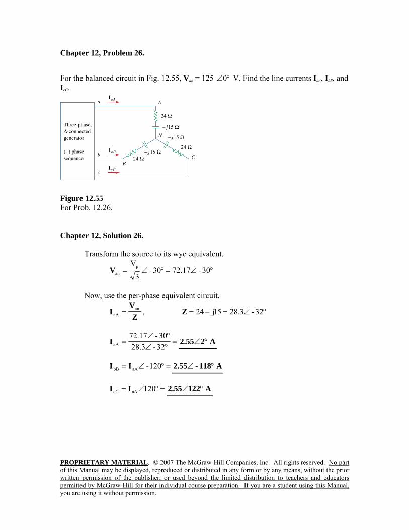
Chapter 12, Problem 26. For the balanced circuit in Fig. 12.55, Vab = 125 °∠0 V. Find the line currents IaA, IbB, and IcC.
Figure 12.55 For Prob. 12.26. Chapter 12, Solution 26. Transform the source to its wye equivalent.
°∠=°∠= 30-17.7230-3
VpanV
Now, use the per-phase equivalent circuit.
ZV
I anaA = , °∠=−= 32-3.2815j24Z
=°∠°∠
=32-3.2830-17.72
aAI A255.2 °∠
=°∠= 120-aAbB II A118-55.2 °∠
=°∠= 120aAcC II A12255.2 °∠
PROPRIETARY MATERIAL. © 2007 The McGraw-Hill Companies, Inc. All rights reserved. No part of this Manual may be displayed, reproduced or distributed in any form or by any means, without the prior written permission of the publisher, or used beyond the limited distribution to teachers and educators permitted by McGraw-Hill for their individual course preparation. If you are a student using this Manual, you are using it without permission.
Chapter 12, Problem 27.
A ∆-connected source supplies power to a Y-connected load in a three-phase balanced system. Given that the line impedance is 2 + j1 Ω per phase while the load impedance is 6 + j4 Ω per phase, find the magnitude of the line voltage at the load. Assume the source phase voltage Vab = 208 °∠0 V rms.
Chapter 12, Solution 27. Since ZL and Zl are in series, we can lump them together so that 2 6 4 8 5YZ j j j= + + + = +
30
208 3033(8 5)
oPo
aY
V
IZ j
< −< −
= =+
208(0.866 0.5)(6 4)(6 4) 80.81 43.543(8 5)L a
j jV j I jj
− += + = = −
+
|VL| = 91.79 V
Chapter 12, Problem 28. The line-to-line voltages in a Y-load have a magnitude of 440 V and are in the positive sequence at 60 Hz. If the loads are balanced with Z1 = Z 2 = Z 3 = 25 °∠30 , find all line currents and phase voltages.
Chapter 12, Solution 28.
PabL V3440VV === or VP = 440/1.7321 = 254 For reference, let VAN = 254∠0˚ V which leads to VBN = 254∠–120˚ V and VCN = 254∠120˚ V. The line currents are found as follows, Ia = VAN/ZY = 254/25∠30˚ = 10.16∠–30˚ A.
This leads to, Ib = 10.16∠–150˚ A and Ic = 10.16∠90˚ A.

PROPRIETARY MATERIAL. © 2007 The McGraw-Hill Companies, Inc. All rights reserved. No part of this Manual may be displayed, reproduced or distributed in any form or by any means, without the prior written permission of the publisher, or used beyond the limited distribution to teachers and educators permitted by McGraw-Hill for their individual course preparation. If you are a student using this Manual, you are using it without permission.
Chapter 12, Problem 29.
A balanced three-phase Y-∆ system has Van = 120 °∠0 V rms and Ω+=∆ 4551 jZ . If the line impedance per phase is 0.4 + j1.2 Ω , find the total complex power delivered to the load.
Chapter 12, Solution 29. We can replace the delta load with a wye load, ZY = Z∆/3 = 17+j15Ω. The per-phase equivalent circuit is shown below. Zl Van ZY
120 5.0475 42.95517 15 0.4 1.2
oana
Y
VIZ Z j j
= = = < −+ + + +l
2 23 3 | | 3(5.0475) (17 15) 1.3 1.1465 kVAp a YS S I Z j j= = = + = +
+ _
5.0475∠–42.96˚
PROPRIETARY MATERIAL. © 2007 The McGraw-Hill Companies, Inc. All rights reserved. No part of this Manual may be displayed, reproduced or distributed in any form or by any means, without the prior written permission of the publisher, or used beyond the limited distribution to teachers and educators permitted by McGraw-Hill for their individual course preparation. If you are a student using this Manual, you are using it without permission.
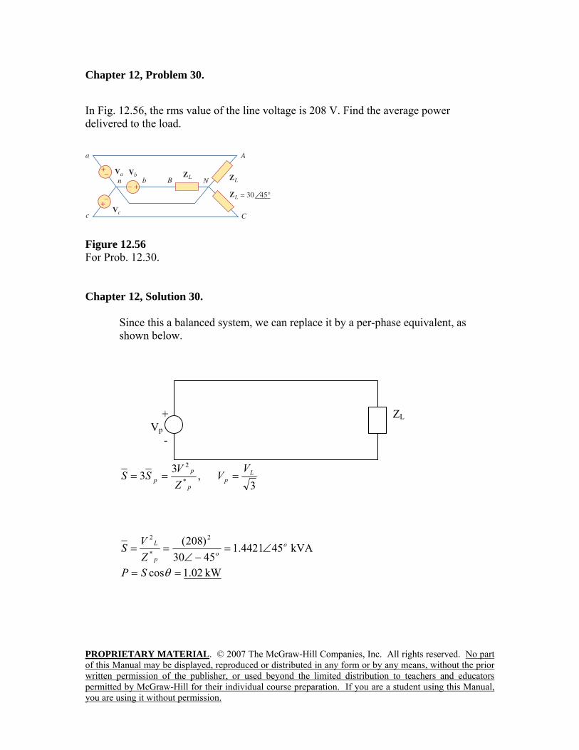
Chapter 12, Problem 30. In Fig. 12.56, the rms value of the line voltage is 208 V. Find the average power delivered to the load.
Figure 12.56 For Prob. 12.30. Chapter 12, Solution 30.
Since this a balanced system, we can replace it by a per-phase equivalent, as shown below. + ZL Vp
-
3,33 *
2L
pp
pp
VV
ZVSS ===
kVA 454421.14530)208( 2
*
2o
op
L
ZVS ∠=
−∠==
kW 02.1cos == θSP
PROPRIETARY MATERIAL. © 2007 The McGraw-Hill Companies, Inc. All rights reserved. No part of this Manual may be displayed, reproduced or distributed in any form or by any means, without the prior written permission of the publisher, or used beyond the limited distribution to teachers and educators permitted by McGraw-Hill for their individual course preparation. If you are a student using this Manual, you are using it without permission.
Chapter 12, Problem 31. A balanced delta-connected load is supplied by a 60-Hz three-phase source with a line voltage of 240 V. Each load phase draws 6 kW at a lagging power factor of 0.8. Find: (a) the load impedance per phase (b) the line current (c) the value of capacitance needed to be connected in parallel with each load phase to minimize the current from the source Chapter 12, Solution 31. (a)
kVA 5.78.0/6cos
,8.0cos,000,6 =====θ
θ Ppp
PSP
kVAR 5.4sin == θPp SQ
kVA 5.1318)5.46(33 jjSS p +=+== For delta-connected load, Vp = VL= 240 (rms). But
Ω+=+
==⎯→⎯= 608.4144.6,10)5.1318(
)240(3333
22*
*
2
jZxjS
VZZVS P
pp
p
p
(b) A 04.188.02403
6000cos3 ==⎯→⎯=xx
IIVP LLLp θ
(c ) We find C to bring the power factor to unity
F 2.207240602
4500kVA 5.4 22 µπω
===⎯→⎯==xxV
QCQQ
rms
cpc
PROPRIETARY MATERIAL. © 2007 The McGraw-Hill Companies, Inc. All rights reserved. No part of this Manual may be displayed, reproduced or distributed in any form or by any means, without the prior written permission of the publisher, or used beyond the limited distribution to teachers and educators permitted by McGraw-Hill for their individual course preparation. If you are a student using this Manual, you are using it without permission.
Chapter 12, Problem 32. A balanced Y-load is connected to a 60-Hz three-phase source with Vab = 240 °∠0 V. The load has pf = 0.5 lagging and each phase draws 5 kW. (a) Determine the load impedance ZY . (b) Find Ia, Ib, and Ic. Chapter 12, Solution 32.
(a) 240| | 3 240 138.563ab p pV V V= = ⎯⎯→ = =
30oan pV V= < −
0.5 cos 60opf θ θ= = ⎯⎯→ =
5cos 10 kVAcos 0.5
PP S Sθθ
= ⎯⎯→ = = =
sin 10sin 60 8.66Q S θ= = = 5 8.66 kVApS j= + But
2 2 2
** 3
138.56 0.96 1.663(5 8.66) 10
p pP p
p p
V VS Z j
Z S j x= ⎯⎯→ = = = −
+
Zp = 0.96 + j1.663 Ω
(b) 138.56 30 72.17 90 A0.96 1.6627
ooan
aY
VIZ j
< −= = = < −
+
120 72.17 210 Ao ob aI I= < − = < −
120 72.17 30 Ao oc aI I= < + = <
PROPRIETARY MATERIAL. © 2007 The McGraw-Hill Companies, Inc. All rights reserved. No part of this Manual may be displayed, reproduced or distributed in any form or by any means, without the prior written permission of the publisher, or used beyond the limited distribution to teachers and educators permitted by McGraw-Hill for their individual course preparation. If you are a student using this Manual, you are using it without permission.
Chapter 12, Problem 33.
A three-phase source delivers 4800 VA to a wye-connected load with a phase voltage of 208 V and a power factor of 0.9 lagging. Calculate the source line current and the source line voltage. Chapter 12, Solution 33. θ∠= LLIV3S
LLIV3S == S
For a Y-connected load,
pL II = , pL V3V =
pp IV3S =
====)208)(3(
4800V3S
IIp
pL A69.7
=×== 2083V3V pL V3.360
Chapter 12, Problem 34.
A balanced wye-connected load with a phase impedance of 10 – j16 Ω is connected to a balanced three-phase generator with a line voltage of 220 V. Determine the line current and the complex power absorbed by the load. Chapter 12, Solution 34.
3
2203
VV L
p ==
°∠=°−∠
=−
== 58732.658868.18
02.127)16j10(3
220V
Y
pa Z
I
== pL II 6.732A
°−∠=°∠××=θ∠= 58256558-732.62203IV3 LLS
S = 1359.2–j2175 VA
Chapter 12, Problem 35.
PROPRIETARY MATERIAL. © 2007 The McGraw-Hill Companies, Inc. All rights reserved. No part of this Manual may be displayed, reproduced or distributed in any form or by any means, without the prior written permission of the publisher, or used beyond the limited distribution to teachers and educators permitted by McGraw-Hill for their individual course preparation. If you are a student using this Manual, you are using it without permission.
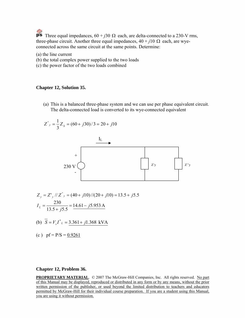
Three equal impedances, 60 + j30 Ω each, are delta-connected to a 230-V rms, three-phase circuit. Another three equal impedances, 40 + j10 Ω each, are wye-connected across the same circuit at the same points. Determine: (a) the line current (b) the total complex power supplied to the two loads (c) the power factor of the two loads combined Chapter 12, Solution 35.
(a) This is a balanced three-phase system and we can use per phase equivalent circuit. The delta-connected load is converted to its wye-connected equivalent
10203/)3060(31'' jjZZ y +=+== ∆
IL
+ 230 V Z’y Z’’y
-
5.55.13)1020//()1040(//' '' jjjZZZ yyy +=++==
A 953.561.145.55.13
230 jj
I L −=+
=
(b) kVA 368.1361.3* jIVS Ls +== (c ) pf = P/S = 0.9261
Chapter 12, Problem 36.
PROPRIETARY MATERIAL. © 2007 The McGraw-Hill Companies, Inc. All rights reserved. No part of this Manual may be displayed, reproduced or distributed in any form or by any means, without the prior written permission of the publisher, or used beyond the limited distribution to teachers and educators permitted by McGraw-Hill for their individual course preparation. If you are a student using this Manual, you are using it without permission.
A 4200-V, three-phase transmission line has an impedance of 4 + j10 Ω per phase. If it supplies a load of 1 MVA at 0.75 power factor (lagging), find:
(a) the complex power (b) the power loss in the line (c) the voltage at the sending end
Chapter 12, Solution 36. (a) S = 1 [0.75 + sin(cos-10.75) ] = 0.75 + j0.6614 MVA
(b) 49.5252.5942003
10)6614.075.0(3
36
** jx
xjVSIIVS
p
ppp +=+
==⎯→⎯=
kW 19.25)4()36.79(|| 22 === lpL RIP
(c) kV 2.709-4.443 kV 21.04381.4)4( o∠=−=++= jjIVV pLs
Chapter 12, Problem 37.
PROPRIETARY MATERIAL. © 2007 The McGraw-Hill Companies, Inc. All rights reserved. No part of this Manual may be displayed, reproduced or distributed in any form or by any means, without the prior written permission of the publisher, or used beyond the limited distribution to teachers and educators permitted by McGraw-Hill for their individual course preparation. If you are a student using this Manual, you are using it without permission.
The total power measured in a three-phase system feeding a balanced wye-connected load is 12 kW at a power factor of 0.6 leading. If the line voltage is 208 V, calculate the line current IL and the load impedance ZY. Chapter 12, Solution 37.
206.0
12pfP
S ===
kVA16j1220S −=θ∠=θ∠=S
But θ∠= LLIV3S
=××
=20831020
I3
L A51.55
p
2
p3 ZIS = For a Y-connected load, pL II = .
2
3
2
L
p )51.55)(3(10)16j12(
I3
×−==
SZ
=pZ Ω− 731.1j298.1
Chapter 12, Problem 38.
PROPRIETARY MATERIAL. © 2007 The McGraw-Hill Companies, Inc. All rights reserved. No part of this Manual may be displayed, reproduced or distributed in any form or by any means, without the prior written permission of the publisher, or used beyond the limited distribution to teachers and educators permitted by McGraw-Hill for their individual course preparation. If you are a student using this Manual, you are using it without permission.
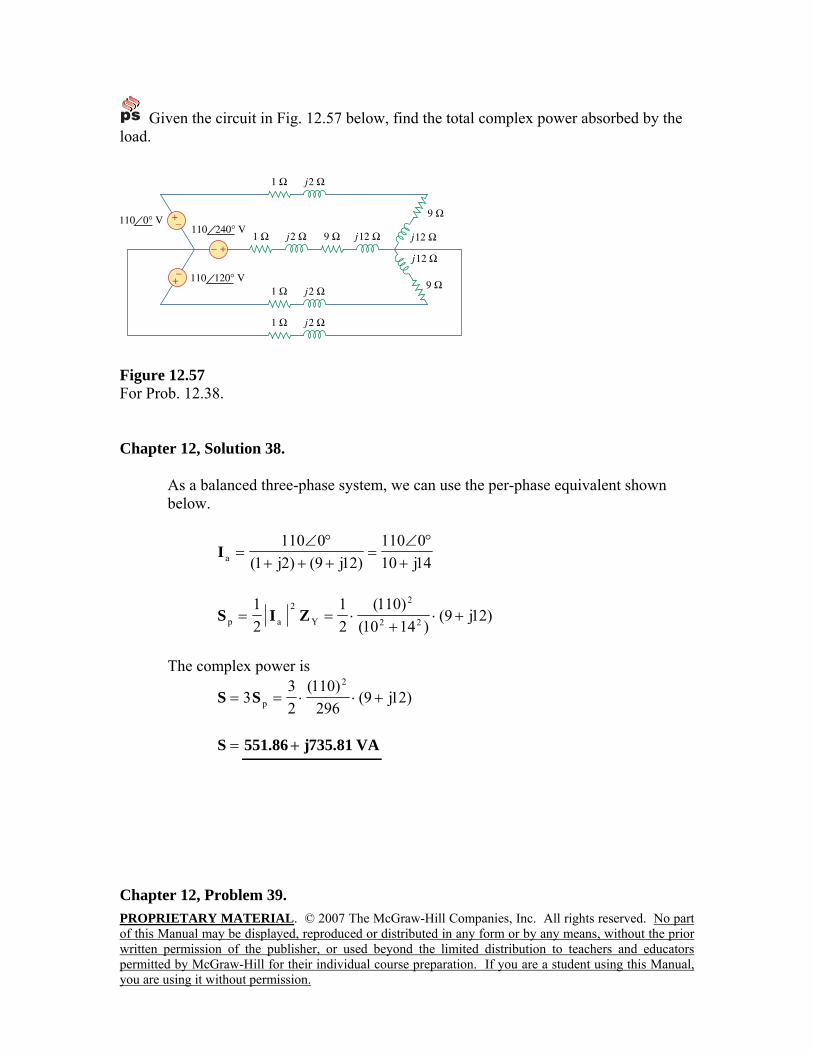
Given the circuit in Fig. 12.57 below, find the total complex power absorbed by the load.
Figure 12.57 For Prob. 12.38. Chapter 12, Solution 38.
As a balanced three-phase system, we can use the per-phase equivalent shown below.
14j100110
)12j9()2j1(0110
a +°∠
=+++°∠
=I
)12j9()1410(
)110(21
21
22
2
Y
2
ap +⋅+
⋅== ZIS
The complex power is
)12j9(296
)110(23
32
p +⋅⋅== SS
=S VA81.735j86.551 +
Chapter 12, Problem 39.
PROPRIETARY MATERIAL. © 2007 The McGraw-Hill Companies, Inc. All rights reserved. No part of this Manual may be displayed, reproduced or distributed in any form or by any means, without the prior written permission of the publisher, or used beyond the limited distribution to teachers and educators permitted by McGraw-Hill for their individual course preparation. If you are a student using this Manual, you are using it without permission.
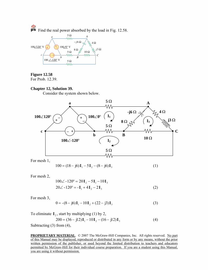
Find the real power absorbed by the load in Fig. 12.58.
Figure 12.58 For Prob. 12.39. Chapter 12, Solution 39. Consider the system shown below.
For mesh 1, 321 )6j8(5)6j18(100 III −−−−= (1)
For mesh 2,
312 10520120-100 III −−=°∠
321 24-120-20 III −+=°∠ (2) For mesh 3,
321 )3j22(10)6j8(-0 III −+−−= (3) To eliminate 2I , start by multiplying (1) by 2,
321 )12j16(10)12j36(200 III −−−−= (4) Subtracting (3) from (4),
− + 100∠0°100∠120°
100∠-120°
− +
−+
a
b c
4 Ω
8 Ω
A
CB
j3 Ω
10 Ω
-j6 Ω
5 Ω
5 Ω
5 Ω
I3 I1
I2
PROPRIETARY MATERIAL. © 2007 The McGraw-Hill Companies, Inc. All rights reserved. No part of this Manual may be displayed, reproduced or distributed in any form or by any means, without the prior written permission of the publisher, or used beyond the limited distribution to teachers and educators permitted by McGraw-Hill for their individual course preparation. If you are a student using this Manual, you are using it without permission.
31 )15j38()18j44(200 II −−−= (5) Multiplying (2) by 45 ,
321 5.2525.1-120-25 III −+=°∠ (6) Adding (1) and (6),
31 )6j5.10()6j75.16(65.21j5.87 II −−−=− (7) In matrix form, (5) and (7) become
⎥⎦
⎤⎢⎣
⎡⎥⎦
⎤⎢⎣
⎡+−+−
=⎥⎦
⎤⎢⎣
⎡− 3
1
6j5.10-6j75.1615j38-18j44
65.12j5.87200
II
25.26j5.192 −=∆ , 2.935j25.9001 −=∆ , 6.1327j3.1103 −=∆
144.4j242.538.33-682.67.76-28.194
46.09-1.129811 −=°∠=
°∠°∠
=∆∆
=I
694.6j485.177.49-857.67.76-28.194
85.25-2.133233 −=°∠=
°∠°∠
=∆∆
=I
We obtain 2I from (6),
312 21
41
120-5 III ++°∠=
)347.3j7425.0()0359.1j3104.1()33.4j-2.5(2 −+−+−=I 713.8j4471.0-2 −=I
The average power absorbed by the 8-Ω resistor is
W89.164)8(551.2j756.3)8(P22
311 =+=−= II The average power absorbed by the 4-Ω resistor is
W1.188)4()8571.6()4(P 22
32 === I The average power absorbed by the 10-Ω resistor is
W12.78)10(019.2j1.9321-)10(P 22323 =−=−= II
Thus, the total real power absorbed by the load is
=++= 321 PPPP W1.431
PROPRIETARY MATERIAL. © 2007 The McGraw-Hill Companies, Inc. All rights reserved. No part of this Manual may be displayed, reproduced or distributed in any form or by any means, without the prior written permission of the publisher, or used beyond the limited distribution to teachers and educators permitted by McGraw-Hill for their individual course preparation. If you are a student using this Manual, you are using it without permission.
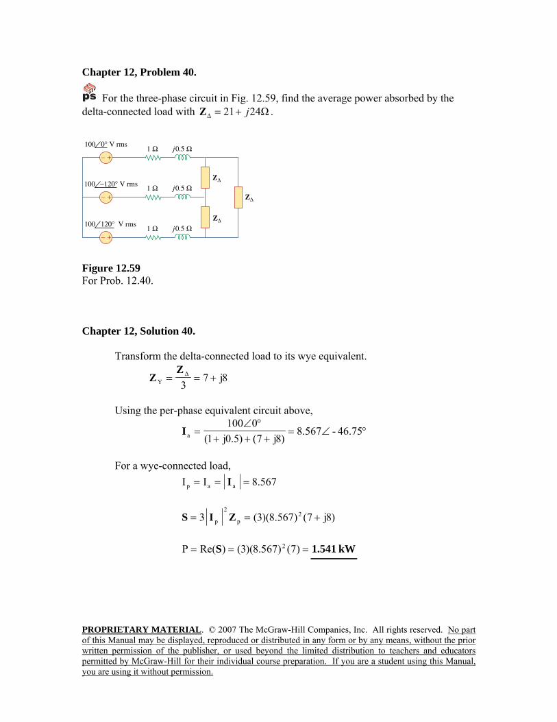
Chapter 12, Problem 40.
For the three-phase circuit in Fig. 12.59, find the average power absorbed by the delta-connected load with Ω2421∆ j+=Z .
Figure 12.59 For Prob. 12.40. Chapter 12, Solution 40. Transform the delta-connected load to its wye equivalent.
8j73Y +== ∆Z
Z
Using the per-phase equivalent circuit above,
°∠=+++
°∠= 46.75-567.8
)8j7()5.0j1(0100
aI
For a wye-connected load,
567.8II aap === I
)8j7()567.8)(3(3 2p
2
p +== ZIS
=== )7()567.8)(3()Re(P 2S kW541.1

PROPRIETARY MATERIAL. © 2007 The McGraw-Hill Companies, Inc. All rights reserved. No part of this Manual may be displayed, reproduced or distributed in any form or by any means, without the prior written permission of the publisher, or used beyond the limited distribution to teachers and educators permitted by McGraw-Hill for their individual course preparation. If you are a student using this Manual, you are using it without permission.
Chapter 12, Problem 41. A balanced delta-connected load draws 5 kW at a power factor of 0.8 lagging. If the three-phase system has an effective line voltage of 400 V, find the line current. Chapter 12, Solution 41.
kVA25.68.0
kW5pfP
S ===
But LLIV3S =
=××
==40031025.6
V3S
I3
LL A021.9
Chapter 12, Problem 42. A balanced three-phase generator delivers 7.2 kW to a wye-connected load with impedance 30 – j40Ω per phase. Find the line current IL and the line voltage VL. Chapter 12, Solution 42. The load determines the power factor.
°=θ⎯→⎯==θ 13.53333.13040
tan
(leading)6.0cospf =θ=
kVA6.9j2.7)8.0(6.02.7
j2.7 −=⎟⎠⎞
⎜⎝⎛
−=S
But p
2
p3 ZIS =
80)40j30)(3(
10)6.9j2.7(3
3
p
2
p =−
×−==
ZS
I
A944.8Ip =
== pL II A944.8
=×
==)944.8(3
1012I3
SV
3
LL V6.774
PROPRIETARY MATERIAL. © 2007 The McGraw-Hill Companies, Inc. All rights reserved. No part of this Manual may be displayed, reproduced or distributed in any form or by any means, without the prior written permission of the publisher, or used beyond the limited distribution to teachers and educators permitted by McGraw-Hill for their individual course preparation. If you are a student using this Manual, you are using it without permission.
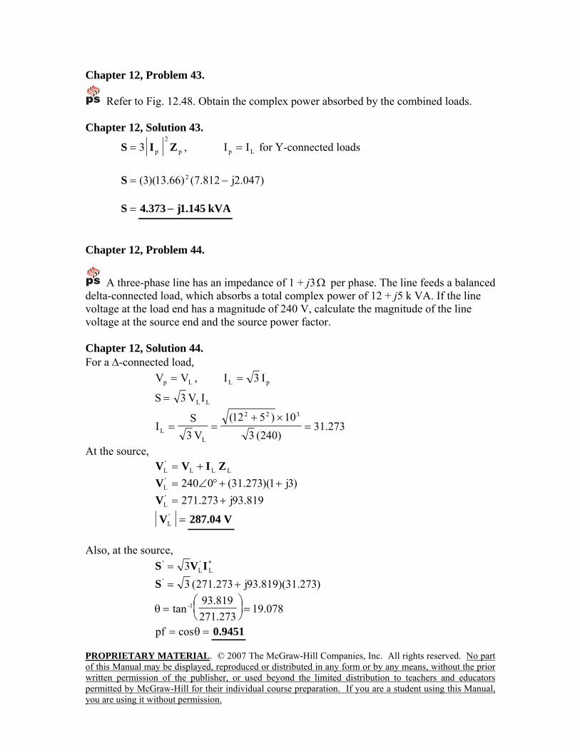
Chapter 12, Problem 43.
Refer to Fig. 12.48. Obtain the complex power absorbed by the combined loads. Chapter 12, Solution 43.
p
2
p3 ZIS = , Lp II = for Y-connected loads
)047.2j812.7()66.13)(3( 2 −=S =S kVA145.1j373.4 −
Chapter 12, Problem 44.
A three-phase line has an impedance of 1 + j3Ω per phase. The line feeds a balanced delta-connected load, which absorbs a total complex power of 12 + j5 k VA. If the line voltage at the load end has a magnitude of 240 V, calculate the magnitude of the line voltage at the source end and the source power factor. Chapter 12, Solution 44. For a ∆-connected load,
Lp VV = , pL I3I =
LLIV3S =
273.31)240(3
10)512(V3
SI
322
LL =
×+==
At the source, LLL
'L ZIVV +=
)3j1)(273.31(0240'L ++°∠=V
819.93j273.271'L +=V
='LV V04.287
Also, at the source,
*L
'L
' 3 IVS = )273.31)(819.93j273.271(3' +=S
078.19273.271
819.93tan 1- =⎟
⎠⎞
⎜⎝⎛
=θ
=θ= cospf 9451.0
PROPRIETARY MATERIAL. © 2007 The McGraw-Hill Companies, Inc. All rights reserved. No part of this Manual may be displayed, reproduced or distributed in any form or by any means, without the prior written permission of the publisher, or used beyond the limited distribution to teachers and educators permitted by McGraw-Hill for their individual course preparation. If you are a student using this Manual, you are using it without permission.
Chapter 12, Problem 45. A balanced wye-connected load is connected to the generator by a balanced transmission line with an impedance of 0.5 + j2Ω per phase. If the load is rated at 450 kW, 0.708 power factor lagging, 440-V line voltage, find the line voltage at the generator. Chapter 12, Solution 45. θ∠= LLIV3S
LL V3
-I
θ∠=
S, kVA6.635
708.010450
pfP 3
=×
==S
A45-8344403
-)6.635(L °∠=
×θ∠
=I
At the source,
)2j5.0(0440 LL ++°∠= IV )76062.2)(45-834(440L °∠°∠+=V
°∠+= 137.1719440LV 7.885j1.1914L +=V
=LV kV.8324109.2 °∠ Note, this is not normally experienced in practice since transformers are use which can significantly reduce line losses.
PROPRIETARY MATERIAL. © 2007 The McGraw-Hill Companies, Inc. All rights reserved. No part of this Manual may be displayed, reproduced or distributed in any form or by any means, without the prior written permission of the publisher, or used beyond the limited distribution to teachers and educators permitted by McGraw-Hill for their individual course preparation. If you are a student using this Manual, you are using it without permission.
Chapter 12, Problem 46. A three-phase load consists of three 100-Ω resistors that can be wye- or delta-connected. Determine which connection will absorb the most average power from a three-phase source with a line voltage of 110 V. Assume zero line impedance. Chapter 12, Solution 46. For the wye-connected load,
pL II = , pL V3V = Zpp VI =
*
2
L*
2
p*pp
3333
ZV
Z
VIVS ===
W121100
)110( 2
*
2
L ===Z
VS
For the delta-connected load,
Lp VV = , pL I3I = , Zpp VI =
*
2
L*
2
p*pp
333
ZV
Z
VIVS ===
W363100
)110)(3( 2
==S
This shows that the delta-connected load will deliver three times more average
power than the wye-connected load. This is also evident from 3Y∆=
ZZ .
PROPRIETARY MATERIAL. © 2007 The McGraw-Hill Companies, Inc. All rights reserved. No part of this Manual may be displayed, reproduced or distributed in any form or by any means, without the prior written permission of the publisher, or used beyond the limited distribution to teachers and educators permitted by McGraw-Hill for their individual course preparation. If you are a student using this Manual, you are using it without permission.
Chapter 12, Problem 47. The following three parallel-connected three-phase loads are fed by a balanced three-phase source: Load 1: 250 kVA, 0.8 pf lagging Load 2: 300 kVA, 0.95 pf leading Load 3: 450 kVA, unity pf If the line voltage is 13.8 kV, calculate the line current and the power factor of the source. Assume that the line impedance is zero. Chapter 12, Solution 47.
°==θ⎯→⎯= 87.36)8.0(cos(lagging)8.0pf -1 kVA150j20087.362501 +=°∠=S
°==θ⎯→⎯= 19.18-)95.0(cos(leading)95.0pf -1
kVA65.93j28519.81-3002 −=°∠=S
°==θ⎯→⎯= 0)1(cos0.1pf -1 kVA4503 =S
kVA45.37.93635.56j935321T °∠=+=++= SSSS
LLT IV3=S
=××
=)108.13(3
107.936I
3
3
L rmsA19.39
=°=θ= )45.3cos(cospf (lagging)9982.0
PROPRIETARY MATERIAL. © 2007 The McGraw-Hill Companies, Inc. All rights reserved. No part of this Manual may be displayed, reproduced or distributed in any form or by any means, without the prior written permission of the publisher, or used beyond the limited distribution to teachers and educators permitted by McGraw-Hill for their individual course preparation. If you are a student using this Manual, you are using it without permission.
Chapter 12, Problem 48.
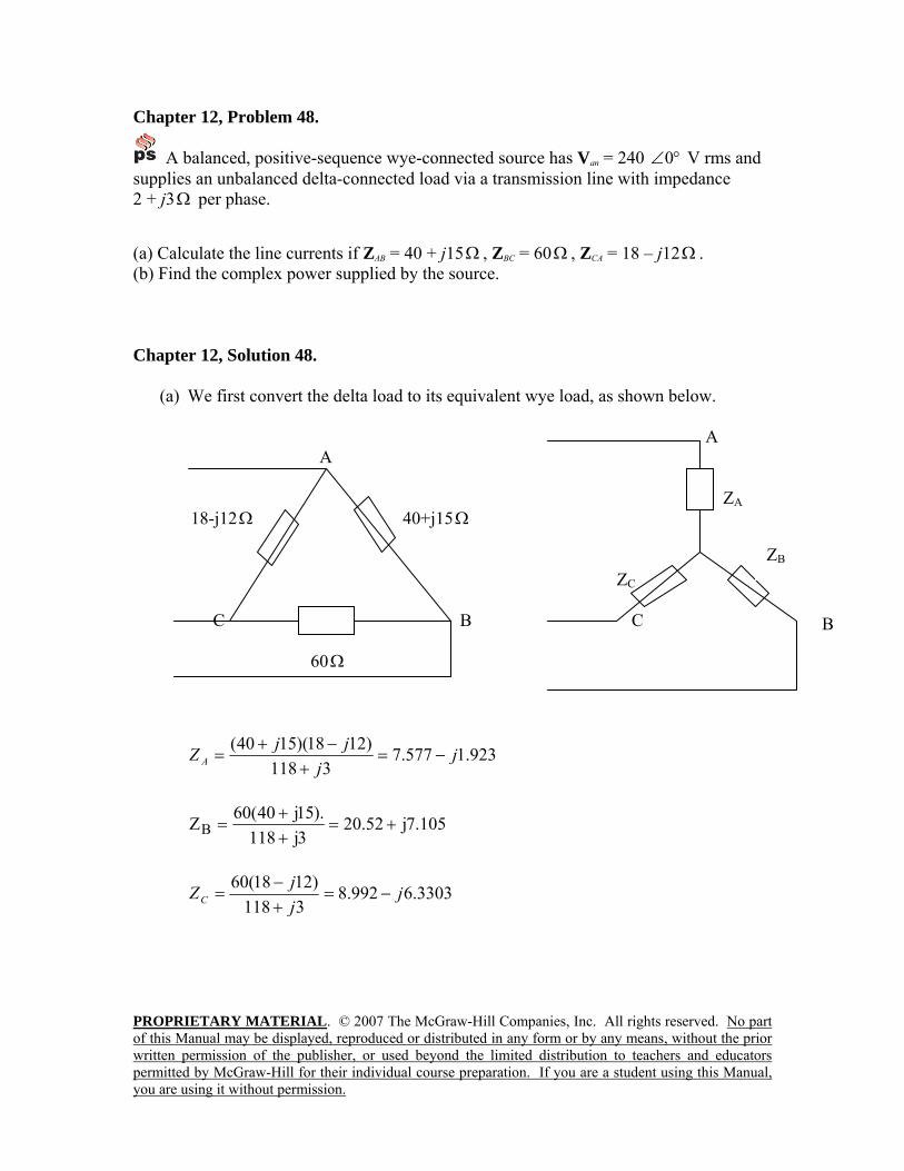
A balanced, positive-sequence wye-connected source has Van = 240 °∠0 V rms and supplies an unbalanced delta-connected load via a transmission line with impedance 2 + j3Ω per phase. (a) Calculate the line currents if ZAB = 40 + j15Ω , ZBC = 60Ω , ZCA = 18 – j12Ω . (b) Find the complex power supplied by the source. Chapter 12, Solution 48.
(a) We first convert the delta load to its equivalent wye load, as shown below. A A ZA 18-j12Ω 40+j15Ω ZC C B C 60Ω
923.1577.73118
)1218)(1540( jj
jjZ A −=+
−+=
105.7j52.203j118
).15j40(60ZB +=++
=
3303.6992.83118
)1218(60 jjjZC −=
+−
=
B
ZB
PROPRIETARY MATERIAL. © 2007 The McGraw-Hill Companies, Inc. All rights reserved. No part of this Manual may be displayed, reproduced or distributed in any form or by any means, without the prior written permission of the publisher, or used beyond the limited distribution to teachers and educators permitted by McGraw-Hill for their individual course preparation. If you are a student using this Manual, you are using it without permission.
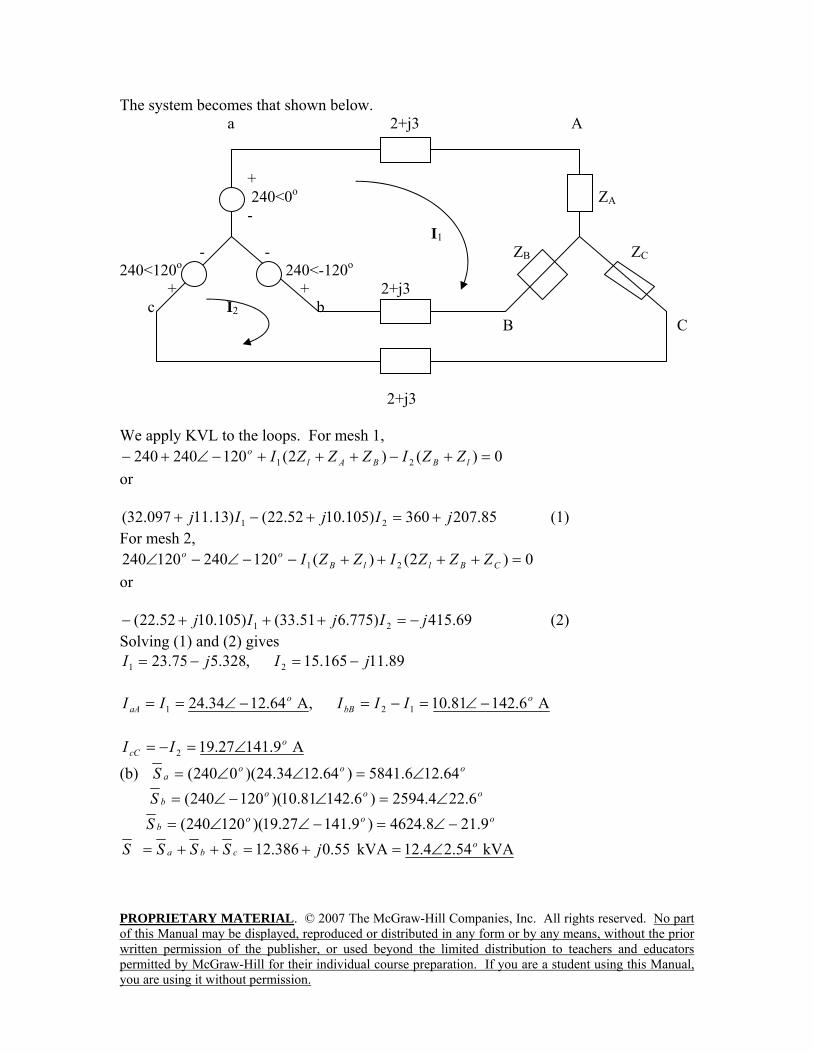
The system becomes that shown below. a 2+j3 A + 240<0o ZA - I1 - - ZB ZC 240<120o 240<-120o + + 2+j3 c I2 b B C 2+j3 We apply KVL to the loops. For mesh 1,
0)()2(120240240 21 =+−+++−∠+− lBBAlo ZZIZZZI
or
85.207360)105.1052.22()13.11097.32( 21 jIjIj +=+−+ (1) For mesh 2,
0)2()(120240120240 21 =++++−−∠−∠ CBllBoo ZZZIZZI
or
69.415)775.651.33()105.1052.22( 21 jIjIj −=+++− (2) Solving (1) and (2) gives
89.11165.15,328.575.23 21 jIjI −=−=
A 6.14281.10,A 64.1234.24 121o
bBo
aA IIIII −∠=−=−∠==
A 9.14127.192o
cC II ∠=−=
(b) oooaS 64.126.5841)64.1234.24)(0240( ∠=∠∠=
ooobS 6.224.2594)6.14281.10)(120240( ∠=∠−∠=
ooobS 9.218.4624)9.14127.19)(120240( −∠=−∠∠=
kVA 54.24.12kVA 55.0386.12 ocba jSSSS ∠=+=++=
PROPRIETARY MATERIAL. © 2007 The McGraw-Hill Companies, Inc. All rights reserved. No part of this Manual may be displayed, reproduced or distributed in any form or by any means, without the prior written permission of the publisher, or used beyond the limited distribution to teachers and educators permitted by McGraw-Hill for their individual course preparation. If you are a student using this Manual, you are using it without permission.
Chapter 12, Problem 49. Each phase load consists of a 20-Ω resistor and a 10-Ω inductive reactance. With a line voltage of 220 V rms, calculate the average power taken by the load if: (a) the three-phase loads are delta-connected (b) the loads are wye-connected Chapter 12, Solution 49.
(a) For the delta-connected load, (rms) 220,1020 ==Ω+= Lpp VVjZ ,
kVA 56.26943.629045808)1020(
22033 2
*
2o
p
p jj
xZVS ∠=+=
−==
or 5.808kW
(b) For the wye-connected load, 3/,1020 Lpp VVjZ =Ω+= ,
kVA 56.26164.2)1020(3
22033 2
*
2o
p
p
jx
ZVS ∠=
−== or 1.9356 kW
Chapter 12, Problem 50. A balanced three-phase source with VL = 240 V rms is supplying 8 kVA at 0.6 power factor lagging to two wye-connected parallel loads. If one load draws 3 kW at unity power factor, calculate the impedance per phase of the second load. Chapter 12, Solution 50.
kVA 3kVA, 4.68.4)8.06.0(8 121 =+=+=+= SjjSSS Hence,
kVA 4.68.112 jSSS +=−=
But p
LLp
p
p
ZVSVV
ZVS *
2
2*
2
2.
3,3
=⎯→⎯==
Ω+=⎯→⎯+
== 34.8346.210)4.68.1(
2403
2
2
** jZ
xjSVZ p
Lp
PROPRIETARY MATERIAL. © 2007 The McGraw-Hill Companies, Inc. All rights reserved. No part of this Manual may be displayed, reproduced or distributed in any form or by any means, without the prior written permission of the publisher, or used beyond the limited distribution to teachers and educators permitted by McGraw-Hill for their individual course preparation. If you are a student using this Manual, you are using it without permission.
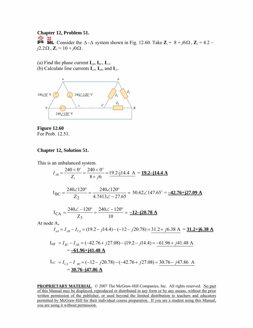
Chapter 12, Problem 51.
Consider the ∆ -∆ system shown in Fig. 12.60. Take Zi = 8 + j6Ω , Z2 = 4.2 –j2.2Ω , Z3 = 10 + j0Ω .
(a) Find the phase current IAB, IBC, ICA. (b) Calculate line currents IaA, IbB, and IcC.
A
Bc C
b
a
+ −
+− +
−240 0° V 240 −120° V
240 120° V
Z1
Z2
Z3
Figure 12.60 For Prob. 12.51.
Chapter 12, Solution 51. This is an unbalanced system.
1
240 0 240 0 19.2-j14.4 A8 6
o o
ABIZ j< <
= = =+
= 19.2–j14.4 A
=−∠
°∠=
°∠=
65.277413.4120240
Z120240I2
BC 50.62∠147.65˚ = –42.76+j27.09 A
=°−∠
=°−∠
=10
120240Z
120240I3
CA –12–j20.78 A
At node A, (19.2 14.4) ( 12 20.78) 31.2 6.38 AaA AB CAI I I j j j= − = − − − − = + = 31.2+j6.38 A
( 42.76 27.08) (19.2 14.4) 61.96 41.48 Ab BC ABI I I j j j= − = − + − − = − +
= –61.96+j41.48 A
( 12 20.78) ( 42.76 27.08) 30.76 47.86 Ac CA BCI I I j j j= − = − − − − + = − = 30.76–j47.86 A
IbB
IcC
PROPRIETARY MATERIAL. © 2007 The McGraw-Hill Companies, Inc. All rights reserved. No part of this Manual may be displayed, reproduced or distributed in any form or by any means, without the prior written permission of the publisher, or used beyond the limited distribution to teachers and educators permitted by McGraw-Hill for their individual course preparation. If you are a student using this Manual, you are using it without permission.
Chapter 12, Problem 52. A four-wire wye-wye circuit has Van = 120 °∠120 , Vbn = 120 °∠0 Vcn = 120 °−∠ 120 V If the impedances are ZAN = 20 °∠60 , ZBN = 30 °∠0 Zcn = 40 Ω°∠30 find the current in the neutral line. Chapter 12, Solution 52. Since the neutral line is present, we can solve this problem on a per-phase basis.
°∠=°∠°∠
== 6066020120120
AN
ana Z
VI
°∠=°∠°∠
== 040300120
BN
bnb Z
VI
°∠=°∠°∠
== 150-33040120-120
CN
cnc Z
VI
Thus,
cban- IIII ++= °∠+°∠+°∠= 150-304606- nI
)5.1j598.2-()4()196.5j3(- n −+++=I °∠=+= 4075.5696.3j405.4- nI
=nI A22075.5 °∠
PROPRIETARY MATERIAL. © 2007 The McGraw-Hill Companies, Inc. All rights reserved. No part of this Manual may be displayed, reproduced or distributed in any form or by any means, without the prior written permission of the publisher, or used beyond the limited distribution to teachers and educators permitted by McGraw-Hill for their individual course preparation. If you are a student using this Manual, you are using it without permission.
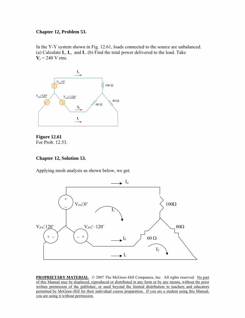
Chapter 12, Problem 53. In the Y-Y system shown in Fig. 12.61, loads connected to the source are unbalanced. (a) Calculate Ia, Ib, and Ic. (b) Find the total power delivered to the load. Take Vp = 240 V rms.
Figure 12.61 For Prob. 12.53.
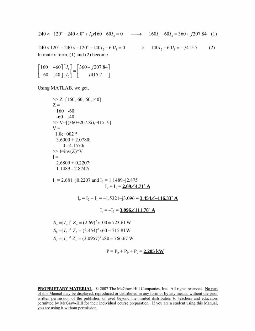
Chapter 12, Solution 53. Applying mesh analysis as shown below, we get. Ia VP∠0˚ 100Ω I1 VP∠120˚ VP∠–120˚ 80Ω Ib 60 Ω I2 Ic
+ _
– + + –
PROPRIETARY MATERIAL. © 2007 The McGraw-Hill Companies, Inc. All rights reserved. No part of this Manual may be displayed, reproduced or distributed in any form or by any means, without the prior written permission of the publisher, or used beyond the limited distribution to teachers and educators permitted by McGraw-Hill for their individual course preparation. If you are a student using this Manual, you are using it without permission.
1 2 1 2240 120 240 0 160 60 0 160 60 360 207.84o o I x I I I j< − − < + − = ⎯⎯→ − = + (1)
2 1 2 1240 120 240 120 140 60 0 140 60 415.7o o I I I I j< − < − + − = ⎯⎯→ − = − (2) In matrix form, (1) and (2) become
1
2
160 60 360 207.8460 140 415.7
I jI j
− +⎡ ⎤⎡ ⎤ ⎡ ⎤=⎢ ⎥⎢ ⎥ ⎢ ⎥− −⎣ ⎦ ⎣ ⎦⎣ ⎦
Using MATLAB, we get,
>> Z=[160,-60;-60,140] Z = 160 -60 -60 140 >> V=[(360+207.8i);-415.7i] V = 1.0e+002 * 3.6000 + 2.0780i 0 - 4.1570i >> I=inv(Z)*V I = 2.6809 + 0.2207i 1.1489 - 2.8747i I1 = 2.681+j0.2207 and I2 = 1.1489–j2.875
Ia = I1 = 2.69∠4.71˚ A
Ib = I2 – I1 = –1.5321–j3.096 = 3.454∠–116.33˚ A
Ic = –I2 = 3.096∠111.78˚ A
2 2| | (2.69) 100 723.61a a aS I Z x= = = W 2 2| | (3.454) 60 715.81b b bS I Z x= = = W 2 2| | (3.0957) 80 766.67c c cS I Z x= = = W
P = Pa + Pb + Pc = 2.205 kW
PROPRIETARY MATERIAL. © 2007 The McGraw-Hill Companies, Inc. All rights reserved. No part of this Manual may be displayed, reproduced or distributed in any form or by any means, without the prior written permission of the publisher, or used beyond the limited distribution to teachers and educators permitted by McGraw-Hill for their individual course preparation. If you are a student using this Manual, you are using it without permission.
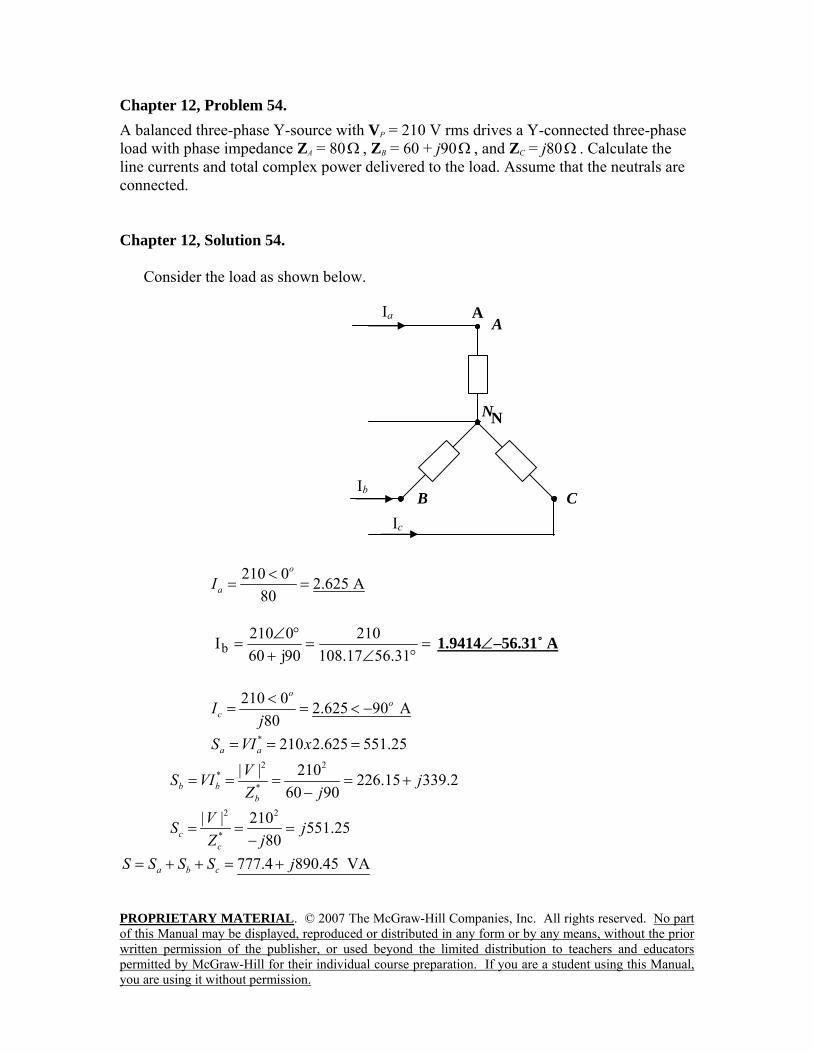
Chapter 12, Problem 54. A balanced three-phase Y-source with VP = 210 V rms drives a Y-connected three-phase load with phase impedance ZA = 80Ω , ZB = 60 + j90Ω , and ZC = j80Ω . Calculate the line currents and total complex power delivered to the load. Assume that the neutrals are connected. Chapter 12, Solution 54.
Consider the load as shown below.
210 0 2.625 A80
o
aI <= =
=°∠
=+
°∠=
31.5617.108210
90j600210Ib 1.9414∠–56.31˚ A
210 0 2.625 90 A80
oo
cIj<
= = < −
* 210 2.625 551.25a aS VI x= = = 2 2
**
| | 210 226.15 339.260 90b b
b
VS VI jZ j
= = = = +−
2 2
*
| | 210 551.2580c
c
VS jZ j
= = =−
777.4 890.45 VAa b cS S S S j= + + = +
N
C
A
N
Ia
Ib
Ic
B
A
PROPRIETARY MATERIAL. © 2007 The McGraw-Hill Companies, Inc. All rights reserved. No part of this Manual may be displayed, reproduced or distributed in any form or by any means, without the prior written permission of the publisher, or used beyond the limited distribution to teachers and educators permitted by McGraw-Hill for their individual course preparation. If you are a student using this Manual, you are using it without permission.
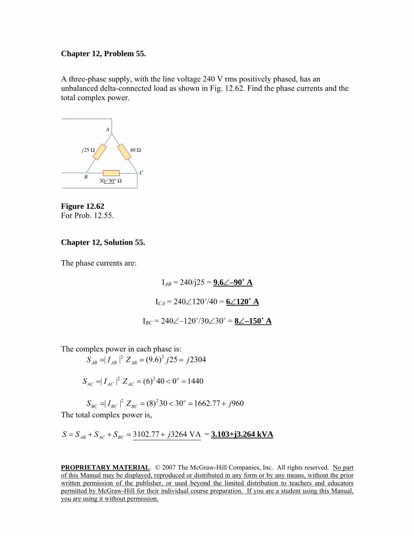
Chapter 12, Problem 55. A three-phase supply, with the line voltage 240 V rms positively phased, has an unbalanced delta-connected load as shown in Fig. 12.62. Find the phase currents and the total complex power.
Figure 12.62 For Prob. 12.55.
Chapter 12, Solution 55. The phase currents are:
IAB = 240/j25 = 9.6∠–90˚ A
ICA = 240∠120˚/40 = 6∠120˚ A
IBC = 240∠–120˚/30∠30˚ = 8∠–150˚ A
The complex power in each phase is: 2 2| | (9.6) 25 2304AB AB ABS I Z j j= = = 2 2| | (6) 40 0 1440o
AC AC ACS I Z= = < =
2 2| | (8) 30 30 1662.77 960oBC BC BCS I Z j= = < = +
The total complex power is,
3102.77 3264 VAAB AC BCS S S S j= + + = + = 3.103+j3.264 kVA
PROPRIETARY MATERIAL. © 2007 The McGraw-Hill Companies, Inc. All rights reserved. No part of this Manual may be displayed, reproduced or distributed in any form or by any means, without the prior written permission of the publisher, or used beyond the limited distribution to teachers and educators permitted by McGraw-Hill for their individual course preparation. If you are a student using this Manual, you are using it without permission.
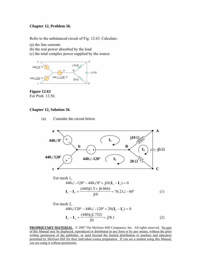
Chapter 12, Problem 56. Refer to the unbalanced circuit of Fig. 12.63. Calculate: (a) the line currents (b) the real power absorbed by the load (c) the total complex power supplied by the source
Figure 12.63 For Prob. 12.56. Chapter 12, Solution 56.
(a) Consider the circuit below.
For mesh 1,
0)(10j0440120-440 31 =−+°∠−°∠ II
°∠=+
=− 60-21.7610j
)866.0j5.1)(440(31 II (1)
For mesh 2,
0)(20120-440120440 32 =−+°∠−°∠ II
1.38j20
)732.1j)(440(23 ==− II (2)
j10 Ω
20 Ω
-j5 ΩI3
A
C
B
− +
440∠0°
440∠120° 440∠-120°
− +
− +
a
b
c
I1
I2
PROPRIETARY MATERIAL. © 2007 The McGraw-Hill Companies, Inc. All rights reserved. No part of this Manual may be displayed, reproduced or distributed in any form or by any means, without the prior written permission of the publisher, or used beyond the limited distribution to teachers and educators permitted by McGraw-Hill for their individual course preparation. If you are a student using this Manual, you are using it without permission.
For mesh 3, 05j)(20)(10j 32313 =−−+− IIIII
Substituting (1) and (2) into the equation for mesh 3 gives,
°∠=+
= 6042.152j5
j0.866)-1.5)(440(3I (3)
From (1),
°∠=+=°∠+= 3013266j315.11460-21.7631 II From (2),
°∠=+=−= 50.9493.1209.93j21.761.38j32 II
== 1a II A30132 °∠
=+=−= j27.9-38.10512b III A143.823.47 °∠
== 2c -II A230.99.120 °∠
(b) kVA08.58j)10j(2
31AB =−= IIS
kVA04.29)20(2
32BC =−= IIS
kVA-j116.16-j5)((152.42)-j5)( 22
3CA === IS
kVA08.58j04.29CABCAB −=++= SSSS Real power absorbed = kW04.29
(c) Total complex supplied by the source is =S kVA08.58j04.29 −
PROPRIETARY MATERIAL. © 2007 The McGraw-Hill Companies, Inc. All rights reserved. No part of this Manual may be displayed, reproduced or distributed in any form or by any means, without the prior written permission of the publisher, or used beyond the limited distribution to teachers and educators permitted by McGraw-Hill for their individual course preparation. If you are a student using this Manual, you are using it without permission.
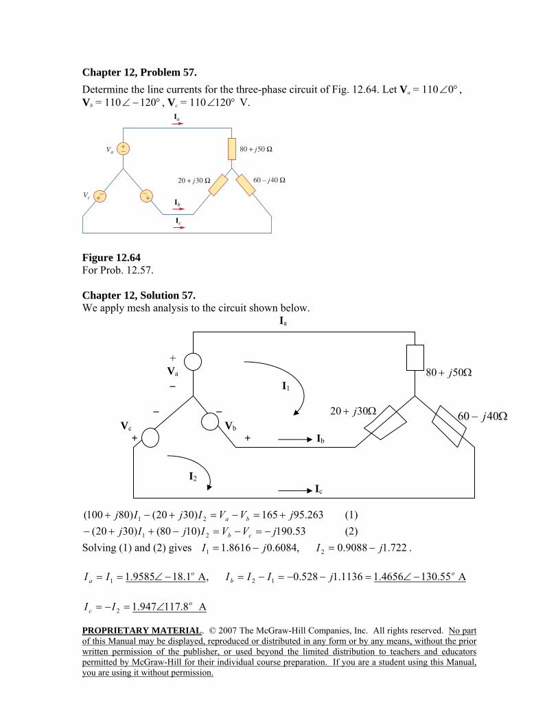
Chapter 12, Problem 57. Determine the line currents for the three-phase circuit of Fig. 12.64. Let Va = 110 °∠0 , Vb = 110 °−∠ 120 , Vc = 110 °∠120 V.
Figure 12.64 For Prob. 12.57. Chapter 12, Solution 57. We apply mesh analysis to the circuit shown below.
Ia + Va Ω+ 5080 j – I1 – – Ω+ 3020 j
Vc Vb + + Ib
I2 Ic
263.95165)3020()80100( 21 jVVIjIj ba +=−=+−+ (1) 53.190)1080()3020( 21 jVVIjIj cb −=−=−++− (2)
Solving (1) and (2) gives 722.19088.0,6084.08616.1 21 jIjI −=−= .
A 55.1304656.11136.1528.0,A 1.189585.1 121o
bo
a jIIIII −∠=−−=−=−∠==
A 8.117947.12o
c II ∠=−=
Ω− 4060 j
PROPRIETARY MATERIAL. © 2007 The McGraw-Hill Companies, Inc. All rights reserved. No part of this Manual may be displayed, reproduced or distributed in any form or by any means, without the prior written permission of the publisher, or used beyond the limited distribution to teachers and educators permitted by McGraw-Hill for their individual course preparation. If you are a student using this Manual, you are using it without permission.
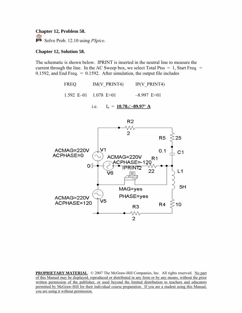
Chapter 12, Problem 58.
Solve Prob. 12.10 using PSpice. Chapter 12, Solution 58. The schematic is shown below. IPRINT is inserted in the neutral line to measure the current through the line. In the AC Sweep box, we select Total Ptss = 1, Start Freq. = 0.1592, and End Freq. = 0.1592. After simulation, the output file includes
FREQ IM(V_PRINT4) IP(V_PRINT4) 1.592 E–01 1.078 E+01 –8.997 E+01
i.e. In = 10.78∠–89.97° A
PROPRIETARY MATERIAL. © 2007 The McGraw-Hill Companies, Inc. All rights reserved. No part of this Manual may be displayed, reproduced or distributed in any form or by any means, without the prior written permission of the publisher, or used beyond the limited distribution to teachers and educators permitted by McGraw-Hill for their individual course preparation. If you are a student using this Manual, you are using it without permission.
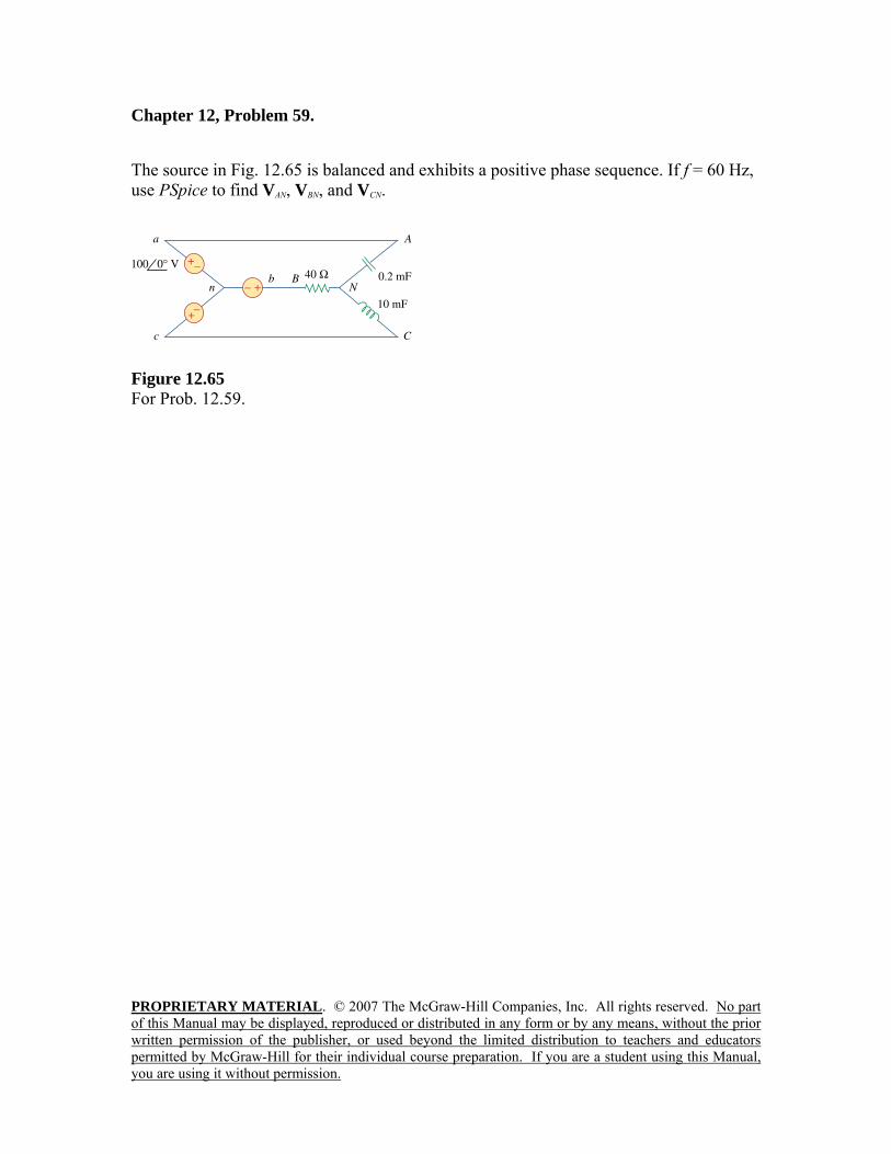
Chapter 12, Problem 59. The source in Fig. 12.65 is balanced and exhibits a positive phase sequence. If f = 60 Hz, use PSpice to find VAN, VBN, and VCN.
Figure 12.65 For Prob. 12.59.
PROPRIETARY MATERIAL. © 2007 The McGraw-Hill Companies, Inc. All rights reserved. No part of this Manual may be displayed, reproduced or distributed in any form or by any means, without the prior written permission of the publisher, or used beyond the limited distribution to teachers and educators permitted by McGraw-Hill for their individual course preparation. If you are a student using this Manual, you are using it without permission.
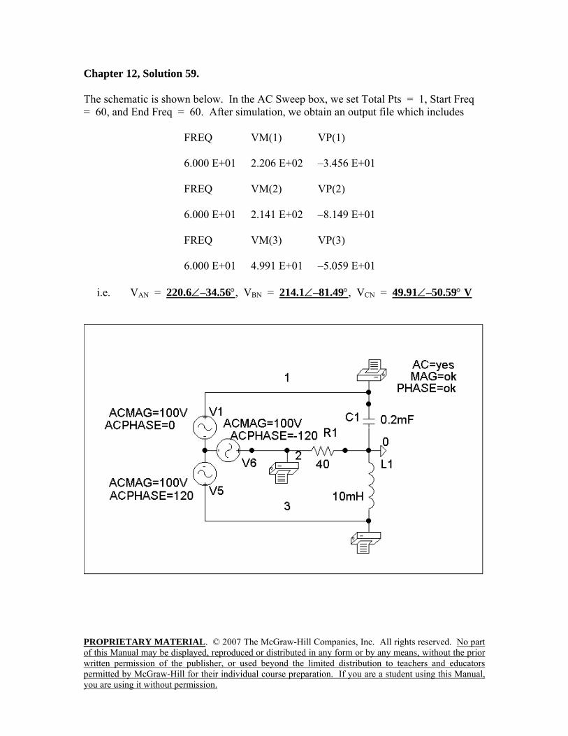
Chapter 12, Solution 59. The schematic is shown below. In the AC Sweep box, we set Total Pts = 1, Start Freq = 60, and End Freq = 60. After simulation, we obtain an output file which includes
FREQ VM(1) VP(1) 6.000 E+01 2.206 E+02 –3.456 E+01 FREQ VM(2) VP(2) 6.000 E+01 2.141 E+02 –8.149 E+01 FREQ VM(3) VP(3) 6.000 E+01 4.991 E+01 –5.059 E+01
i.e. VAN = 220.6∠–34.56°, VBN = 214.1∠–81.49°, VCN = 49.91∠–50.59° V
PROPRIETARY MATERIAL. © 2007 The McGraw-Hill Companies, Inc. All rights reserved. No part of this Manual may be displayed, reproduced or distributed in any form or by any means, without the prior written permission of the publisher, or used beyond the limited distribution to teachers and educators permitted by McGraw-Hill for their individual course preparation. If you are a student using this Manual, you are using it without permission.
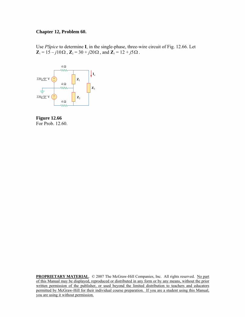
Chapter 12, Problem 60. Use PSpice to determine Io in the single-phase, three-wire circuit of Fig. 12.66. Let Z1 = 15 – j10Ω , Z2 = 30 + j20Ω , and Z3 = 12 + j5Ω .
Figure 12.66 For Prob. 12.60.
PROPRIETARY MATERIAL. © 2007 The McGraw-Hill Companies, Inc. All rights reserved. No part of this Manual may be displayed, reproduced or distributed in any form or by any means, without the prior written permission of the publisher, or used beyond the limited distribution to teachers and educators permitted by McGraw-Hill for their individual course preparation. If you are a student using this Manual, you are using it without permission.
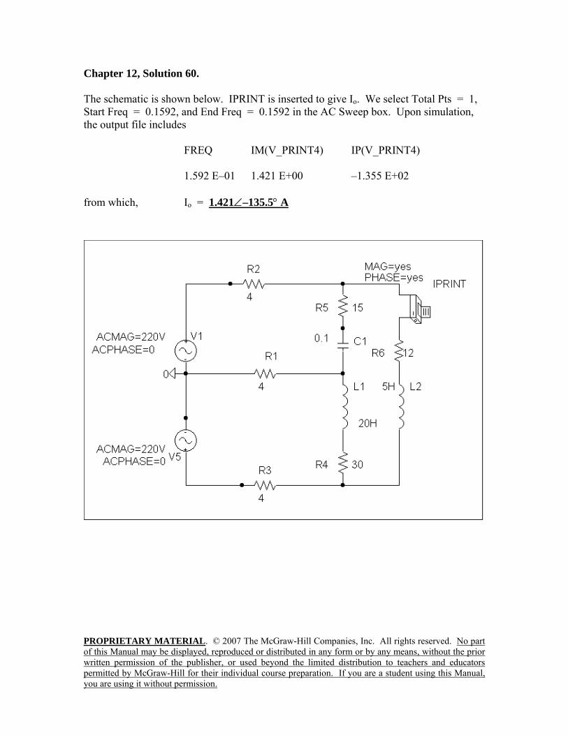
Chapter 12, Solution 60. The schematic is shown below. IPRINT is inserted to give Io. We select Total Pts = 1, Start Freq = 0.1592, and End Freq = 0.1592 in the AC Sweep box. Upon simulation, the output file includes
FREQ IM(V_PRINT4) IP(V_PRINT4) 1.592 E–01 1.421 E+00 –1.355 E+02
from which, Io = 1.421∠–135.5° A
PROPRIETARY MATERIAL. © 2007 The McGraw-Hill Companies, Inc. All rights reserved. No part of this Manual may be displayed, reproduced or distributed in any form or by any means, without the prior written permission of the publisher, or used beyond the limited distribution to teachers and educators permitted by McGraw-Hill for their individual course preparation. If you are a student using this Manual, you are using it without permission.
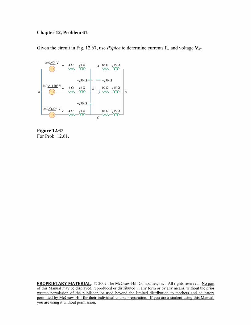
Chapter 12, Problem 61. Given the circuit in Fig. 12.67, use PSpice to determine currents IaA and voltage VBN.
Figure 12.67 For Prob. 12.61.
PROPRIETARY MATERIAL. © 2007 The McGraw-Hill Companies, Inc. All rights reserved. No part of this Manual may be displayed, reproduced or distributed in any form or by any means, without the prior written permission of the publisher, or used beyond the limited distribution to teachers and educators permitted by McGraw-Hill for their individual course preparation. If you are a student using this Manual, you are using it without permission.
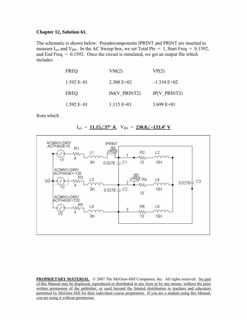
Chapter 12, Solution 61. The schematic is shown below. Pseudocomponents IPRINT and PRINT are inserted to measure IaA and VBN. In the AC Sweep box, we set Total Pts = 1, Start Freq = 0.1592, and End Freq = 0.1592. Once the circuit is simulated, we get an output file which includes
FREQ VM(2) VP(2) 1.592 E–01 2.308 E+02 –1.334 E+02 FREQ IM(V_PRINT2) IP(V_PRINT2) 1.592 E–01 1.115 E+01 3.699 E+01
from which
IaA = 11.15∠37° A, VBN = 230.8∠–133.4° V
PROPRIETARY MATERIAL. © 2007 The McGraw-Hill Companies, Inc. All rights reserved. No part of this Manual may be displayed, reproduced or distributed in any form or by any means, without the prior written permission of the publisher, or used beyond the limited distribution to teachers and educators permitted by McGraw-Hill for their individual course preparation. If you are a student using this Manual, you are using it without permission.
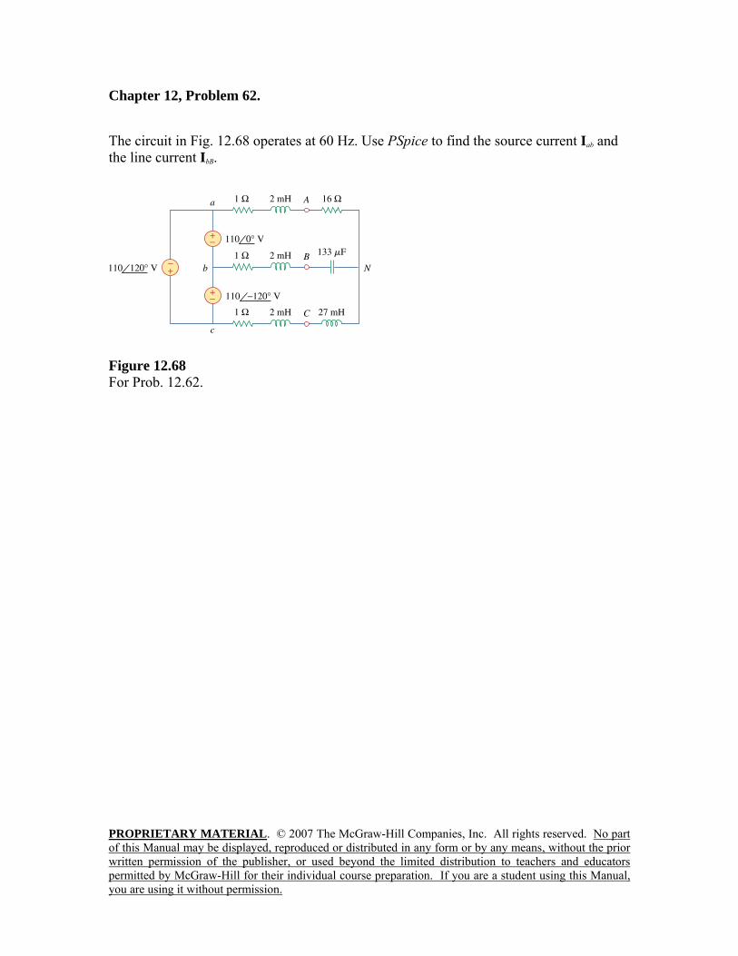
Chapter 12, Problem 62. The circuit in Fig. 12.68 operates at 60 Hz. Use PSpice to find the source current Iab and the line current IbB.
Figure 12.68 For Prob. 12.62.
PROPRIETARY MATERIAL. © 2007 The McGraw-Hill Companies, Inc. All rights reserved. No part of this Manual may be displayed, reproduced or distributed in any form or by any means, without the prior written permission of the publisher, or used beyond the limited distribution to teachers and educators permitted by McGraw-Hill for their individual course preparation. If you are a student using this Manual, you are using it without permission.
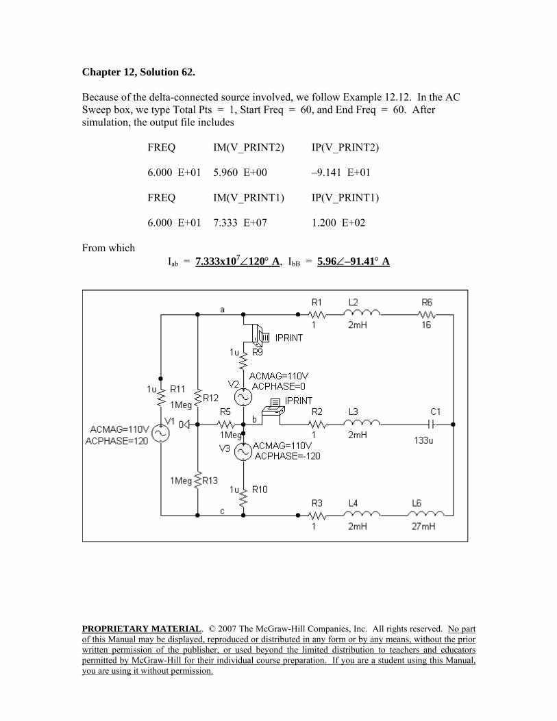
Chapter 12, Solution 62. Because of the delta-connected source involved, we follow Example 12.12. In the AC Sweep box, we type Total Pts = 1, Start Freq = 60, and End Freq = 60. After simulation, the output file includes
FREQ IM(V_PRINT2) IP(V_PRINT2) 6.000 E+01 5.960 E+00 –9.141 E+01 FREQ IM(V_PRINT1) IP(V_PRINT1) 6.000 E+01 7.333 E+07 1.200 E+02
From which
Iab = 7.333x10⁷∠120° A, IbB = 5.96∠–91.41° A
PROPRIETARY MATERIAL. © 2007 The McGraw-Hill Companies, Inc. All rights reserved. No part of this Manual may be displayed, reproduced or distributed in any form or by any means, without the prior written permission of the publisher, or used beyond the limited distribution to teachers and educators permitted by McGraw-Hill for their individual course preparation. If you are a student using this Manual, you are using it without permission.
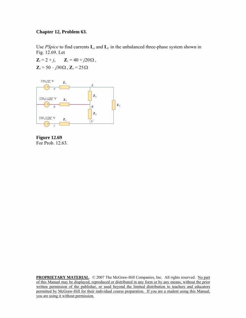
Chapter 12, Problem 63. Use PSpice to find currents IaA and IAC in the unbalanced three-phase system shown in Fig. 12.69. Let ZI = 2 + j, Z1 = 40 + j20Ω , Z2 = 50 – j30Ω , Z3 = 25Ω
220 –120° V
220 120° V
Figure 12.69 For Prob. 12.63.
PROPRIETARY MATERIAL. © 2007 The McGraw-Hill Companies, Inc. All rights reserved. No part of this Manual may be displayed, reproduced or distributed in any form or by any means, without the prior written permission of the publisher, or used beyond the limited distribution to teachers and educators permitted by McGraw-Hill for their individual course preparation. If you are a student using this Manual, you are using it without permission.
Chapter 12, Solution 63.
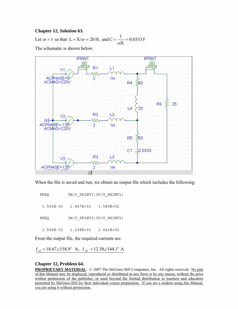
Let F 0333.0X1 C and H, 20X/ L that so 1 =====ω
ωω
The schematic is shown below.
. When the file is saved and run, we obtain an output file which includes the following: FREQ IM(V_PRINT1)IP(V_PRINT1) 1.592E-01 1.867E+01 1.589E+02 FREQ IM(V_PRINT2)IP(V_PRINT2) 1.592E-01 1.238E+01 1.441E+02 From the output file, the required currents are:
A 1.14438.12 A, 9.15867.18 oAC
oaA II ∠=∠=
Chapter 12, Problem 64.
PROPRIETARY MATERIAL. © 2007 The McGraw-Hill Companies, Inc. All rights reserved. No part of this Manual may be displayed, reproduced or distributed in any form or by any means, without the prior written permission of the publisher, or used beyond the limited distribution to teachers and educators permitted by McGraw-Hill for their individual course preparation. If you are a student using this Manual, you are using it without permission.
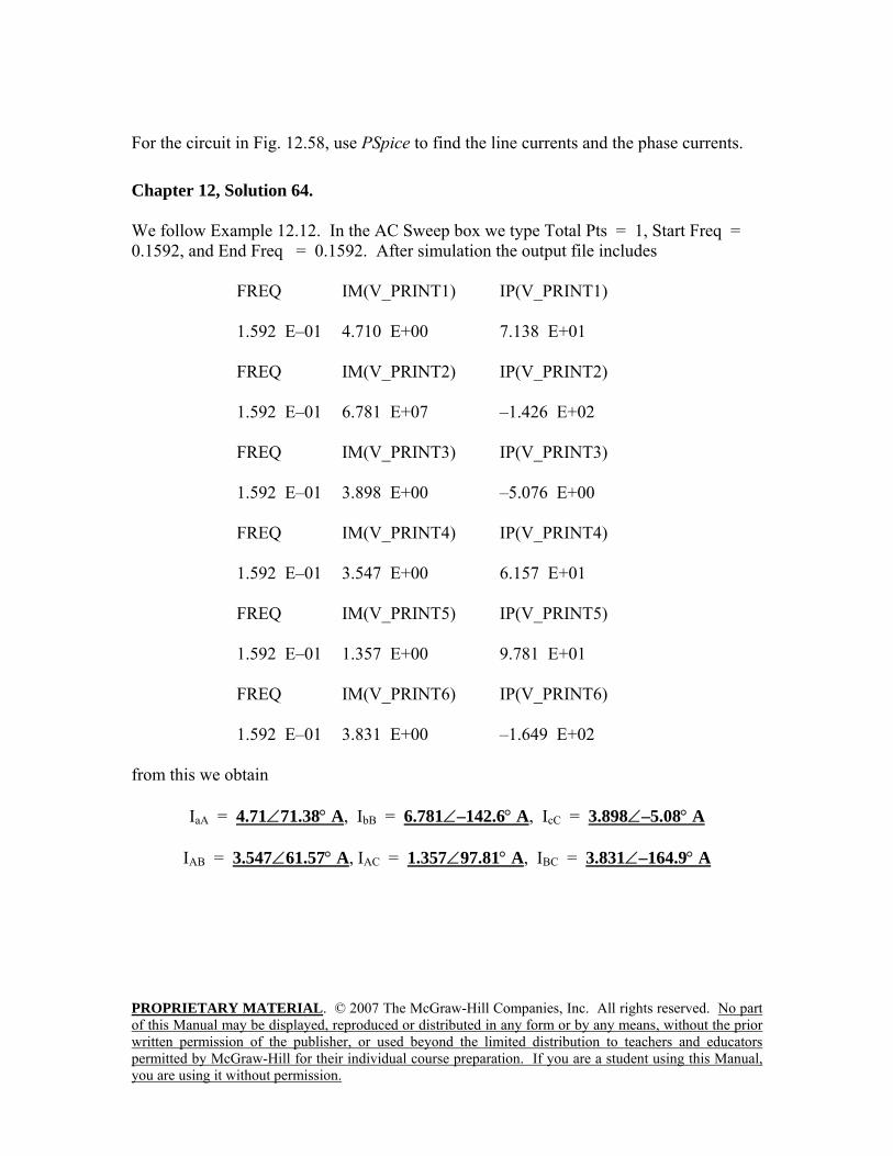
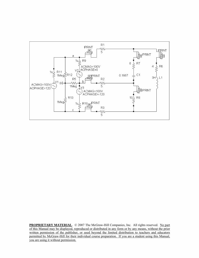
For the circuit in Fig. 12.58, use PSpice to find the line currents and the phase currents. Chapter 12, Solution 64. We follow Example 12.12. In the AC Sweep box we type Total Pts = 1, Start Freq = 0.1592, and End Freq = 0.1592. After simulation the output file includes
FREQ IM(V_PRINT1) IP(V_PRINT1) 1.592 E–01 4.710 E+00 7.138 E+01 FREQ IM(V_PRINT2) IP(V_PRINT2) 1.592 E–01 6.781 E+07 –1.426 E+02 FREQ IM(V_PRINT3) IP(V_PRINT3) 1.592 E–01 3.898 E+00 –5.076 E+00 FREQ IM(V_PRINT4) IP(V_PRINT4) 1.592 E–01 3.547 E+00 6.157 E+01 FREQ IM(V_PRINT5) IP(V_PRINT5) 1.592 E–01 1.357 E+00 9.781 E+01 FREQ IM(V_PRINT6) IP(V_PRINT6) 1.592 E–01 3.831 E+00 –1.649 E+02
from this we obtain
IaA = 4.71∠71.38° A, IbB = 6.781∠–142.6° A, IcC = 3.898∠–5.08° A
IAB = 3.547∠61.57° A, IAC = 1.357∠97.81° A, IBC = 3.831∠–164.9° A
PROPRIETARY MATERIAL. © 2007 The McGraw-Hill Companies, Inc. All rights reserved. No part of this Manual may be displayed, reproduced or distributed in any form or by any means, without the prior written permission of the publisher, or used beyond the limited distribution to teachers and educators permitted by McGraw-Hill for their individual course preparation. If you are a student using this Manual, you are using it without permission.
PROPRIETARY MATERIAL. © 2007 The McGraw-Hill Companies, Inc. All rights reserved. No part of this Manual may be displayed, reproduced or distributed in any form or by any means, without the prior written permission of the publisher, or used beyond the limited distribution to teachers and educators permitted by McGraw-Hill for their individual course preparation. If you are a student using this Manual, you are using it without permission.
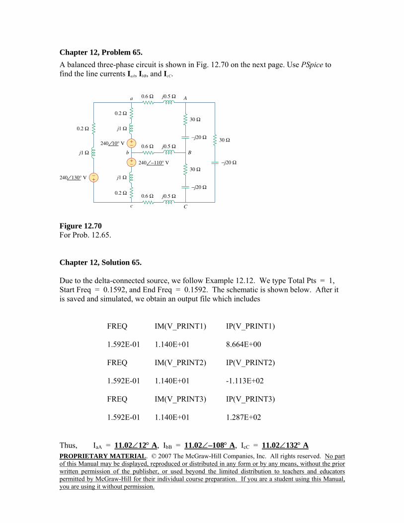
Chapter 12, Problem 65. A balanced three-phase circuit is shown in Fig. 12.70 on the next page. Use PSpice to find the line currents IaA, IbB, and IcC.
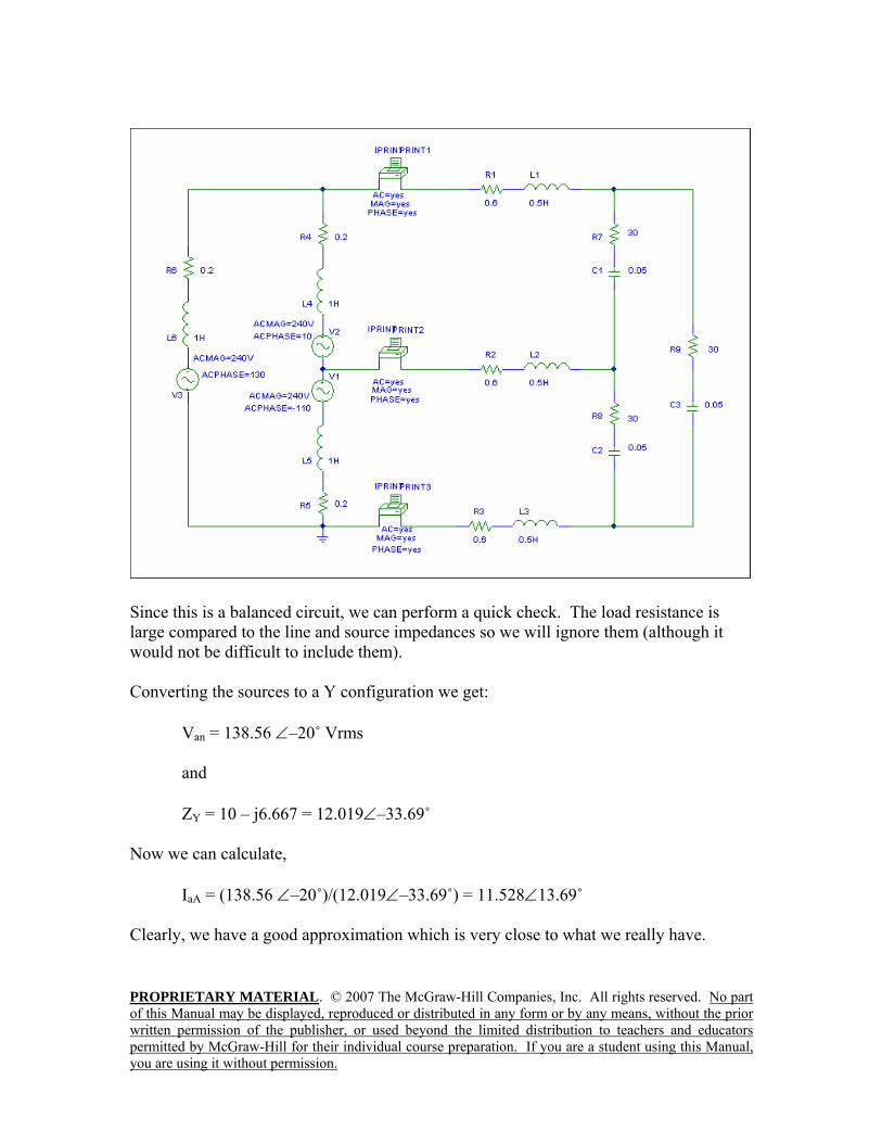
Figure 12.70 For Prob. 12.65. Chapter 12, Solution 65. Due to the delta-connected source, we follow Example 12.12. We type Total Pts = 1, Start Freq = 0.1592, and End Freq = 0.1592. The schematic is shown below. After it is saved and simulated, we obtain an output file which includes
FREQ IM(V_PRINT1) IP(V_PRINT1) 1.592E-01 1.140E+01 8.664E+00 FREQ IM(V_PRINT2) IP(V_PRINT2) 1.592E-01 1.140E+01 -1.113E+02 FREQ IM(V_PRINT3) IP(V_PRINT3) 1.592E-01 1.140E+01 1.287E+02
Thus, IaA = 11.02∠12° A, IbB = 11.02∠–108° A, IcC = 11.02∠132° A
PROPRIETARY MATERIAL. © 2007 The McGraw-Hill Companies, Inc. All rights reserved. No part of this Manual may be displayed, reproduced or distributed in any form or by any means, without the prior written permission of the publisher, or used beyond the limited distribution to teachers and educators permitted by McGraw-Hill for their individual course preparation. If you are a student using this Manual, you are using it without permission.
Since this is a balanced circuit, we can perform a quick check. The load resistance is large compared to the line and source impedances so we will ignore them (although it would not be difficult to include them). Converting the sources to a Y configuration we get:
Van = 138.56 ∠–20˚ Vrms and ZY = 10 – j6.667 = 12.019∠–33.69˚
Now we can calculate,
IaA = (138.56 ∠–20˚)/(12.019∠–33.69˚) = 11.528∠13.69˚
Clearly, we have a good approximation which is very close to what we really have.
PROPRIETARY MATERIAL. © 2007 The McGraw-Hill Companies, Inc. All rights reserved. No part of this Manual may be displayed, reproduced or distributed in any form or by any means, without the prior written permission of the publisher, or used beyond the limited distribution to teachers and educators permitted by McGraw-Hill for their individual course preparation. If you are a student using this Manual, you are using it without permission.
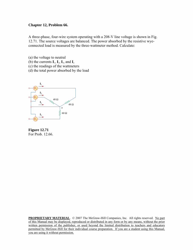
Chapter 12, Problem 66. A three-phase, four-wire system operating with a 208-V line voltage is shown in Fig. 12.71. The source voltages are balanced. The power absorbed by the resistive wye-connected load is measured by the three-wattmeter method. Calculate: (a) the voltage to neutral (b) the currents I1, I2, I3, and In (c) the readings of the wattmeters (d) the total power absorbed by the load
Figure 12.71 For Prob. 12.66.
PROPRIETARY MATERIAL. © 2007 The McGraw-Hill Companies, Inc. All rights reserved. No part of this Manual may be displayed, reproduced or distributed in any form or by any means, without the prior written permission of the publisher, or used beyond the limited distribution to teachers and educators permitted by McGraw-Hill for their individual course preparation. If you are a student using this Manual, you are using it without permission.
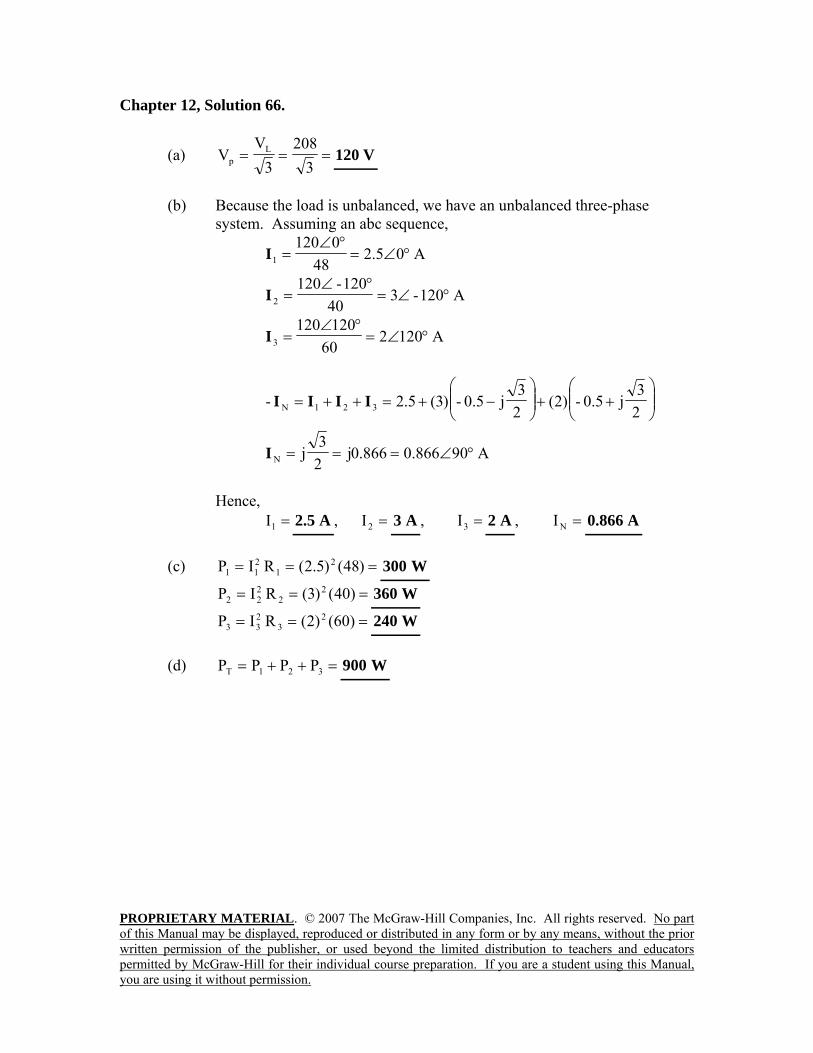
Chapter 12, Solution 66.
(a) ===3
2083
VV L
p V120
(b) Because the load is unbalanced, we have an unbalanced three-phase
system. Assuming an abc sequence,
A05.248
01201 °∠=
°∠=I
A120-340
120-1202 °∠=
°∠=I
A120260
1201203 °∠=
°∠=I
⎟⎟⎠
⎞⎜⎜⎝
⎛++⎟⎟
⎠
⎞⎜⎜⎝
⎛−+=++=
23
j5.0-)2(23
j0.5-)3(5.2- 321N IIII
A90866.0866.0j23
jN °∠===I
Hence,
=1I A5.2 , =2I A3 , =3I A2 , =NI A866.0
(c) === )48()5.2(RIP 21
211 W300
=== )40()3(RIP 22
222 W360
=== )60()2(RIP 23
233 W240
(d) =++= 321T PPPP W900
PROPRIETARY MATERIAL. © 2007 The McGraw-Hill Companies, Inc. All rights reserved. No part of this Manual may be displayed, reproduced or distributed in any form or by any means, without the prior written permission of the publisher, or used beyond the limited distribution to teachers and educators permitted by McGraw-Hill for their individual course preparation. If you are a student using this Manual, you are using it without permission.
Chapter 12, Problem 67.
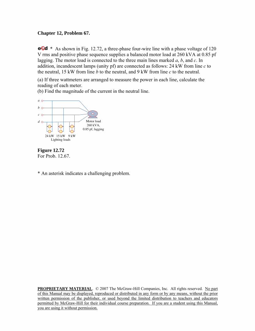
* As shown in Fig. 12.72, a three-phase four-wire line with a phase voltage of 120 V rms and positive phase sequence supplies a balanced motor load at 260 kVA at 0.85 pf lagging. The motor load is connected to the three main lines marked a, b, and c. In addition, incandescent lamps (unity pf) are connected as follows: 24 kW from line c to the neutral, 15 kW from line b to the neutral, and 9 kW from line c to the neutral. (a) If three wattmeters are arranged to measure the power in each line, calculate the reading of each meter. (b) Find the magnitude of the current in the neutral line.
Figure 12.72 For Prob. 12.67. * An asterisk indicates a challenging problem.
PROPRIETARY MATERIAL. © 2007 The McGraw-Hill Companies, Inc. All rights reserved. No part of this Manual may be displayed, reproduced or distributed in any form or by any means, without the prior written permission of the publisher, or used beyond the limited distribution to teachers and educators permitted by McGraw-Hill for their individual course preparation. If you are a student using this Manual, you are using it without permission.
Chapter 12, Solution 67.
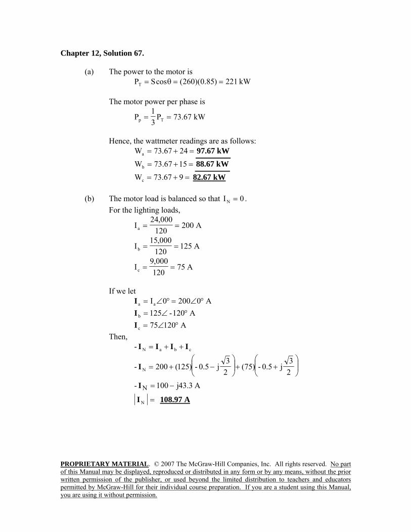
(a) The power to the motor is kW221)85.0)(260(cosSPT ==θ=
The motor power per phase is
kW67.73P31
P Tp ==
Hence, the wattmeter readings are as follows:
=+= 2467.73Wa kW67.97 =+= 1567.73Wb kW67.88 =+= 967.73Wc 82.67 kW
(b) The motor load is balanced so that 0IN = .
For the lighting loads,
A200120
000,24Ia ==
A125120
000,15Ib ==
A75120000,9
Ic ==
If we let
A02000Iaa °∠=°∠=I A120-125b °∠=I
A12075c °∠=I Then,
cbaN- IIII ++=
⎟⎟⎠
⎞⎜⎜⎝
⎛++⎟⎟
⎠
⎞⎜⎜⎝
⎛−+=
23
j0.5-)75(23
j5.0-)125(200- NI
A3.43j100- N −=I
=NI 108.97 A
PROPRIETARY MATERIAL. © 2007 The McGraw-Hill Companies, Inc. All rights reserved. No part of this Manual may be displayed, reproduced or distributed in any form or by any means, without the prior written permission of the publisher, or used beyond the limited distribution to teachers and educators permitted by McGraw-Hill for their individual course preparation. If you are a student using this Manual, you are using it without permission.
Chapter 12, Problem 68. Meter readings for a three-phase wye-connected alternator supplying power to a motor indicate that the line voltages are 330 V, the line currents are 8.4 A, and the total line power is 4.5 kW. Find: (a) the load in VA (b) the load pf (c) the phase current (d) the phase voltage Chapter 12, Solution 68.
(a) === )4.8)(330(3IV3S LL VA4801
(b) SP
cospfcosSP =θ=⎯→⎯θ=
==24.4801
4500pf 9372.0
(c) For a wye-connected load,
== Lp II A4.8
(d) ===3
3303
VV L
p V53.190
PROPRIETARY MATERIAL. © 2007 The McGraw-Hill Companies, Inc. All rights reserved. No part of this Manual may be displayed, reproduced or distributed in any form or by any means, without the prior written permission of the publisher, or used beyond the limited distribution to teachers and educators permitted by McGraw-Hill for their individual course preparation. If you are a student using this Manual, you are using it without permission.
Chapter 12, Problem 69. A certain store contains three balanced three-phase loads. The three loads are: Load 1: 16 kVA at 0.85 pf lagging Load 2: 12 kVA at 0.6 pf lagging Load 3: 8 kW at unity pf The line voltage at the load is 208 V rms at 60 Hz, and the line impedance is 0.4 + j0.8Ω . Determine the line current and the complex power delivered to the loads. Chapter 12, Solution 69.
For load 1, 1 1 1 1 1cos sinS S jSθ θ= + 1 10.85 cos 31.79opf θ θ= = ⎯⎯→ =
1 13.6 8.43S j= + kVA For load 2, 2 12 0.6 12 0.8 7.2 9.6S x j x j= + = + kVA For load 3, 3 8 0S j= + kVA
1 2 3 28.8 18.03S S S S j= + + = + = 28.8+j18.03 kVA But SP = VPIP
* with IP = IL
08.120x3
)18030j28800(VS
IP
P*L
+==
IL = 79.95 – j50.05 = 94.32∠–32.05˚ A. Note, this is relative to 120.08∠0˚ V. If we assume a positive phase rotation and Vab = 208∠0˚, then Van = 120.08∠–30˚ which yields Ia = 94.32∠–62.05˚ A, Ib = 94.32∠177.95˚ A, Ic = 94.32∠57.95˚ A.
PROPRIETARY MATERIAL. © 2007 The McGraw-Hill Companies, Inc. All rights reserved. No part of this Manual may be displayed, reproduced or distributed in any form or by any means, without the prior written permission of the publisher, or used beyond the limited distribution to teachers and educators permitted by McGraw-Hill for their individual course preparation. If you are a student using this Manual, you are using it without permission.
Chapter 12, Problem 70. The two-wattmeter method gives P1 = 1200 W and P2 = –400 W for a three-phase motor running on a 240-V line. Assume that the motor load is wye-connected and that it draws a line current of 6 A. Calculate the pf of the motor and its phase impedance. Chapter 12, Solution 70.
8004001200PPP 21T =−=+=
1600-1200400-PPQ 12T =−=−=
°=θ⎯→⎯===θ -63.43-28001600-
PQ
tanT
T
=θ= cospf (leading)4472.0
406
240IV
ZL
Lp ===
=pZ Ω°∠ 63.43-40
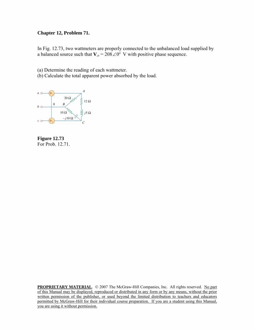
PROPRIETARY MATERIAL. © 2007 The McGraw-Hill Companies, Inc. All rights reserved. No part of this Manual may be displayed, reproduced or distributed in any form or by any means, without the prior written permission of the publisher, or used beyond the limited distribution to teachers and educators permitted by McGraw-Hill for their individual course preparation. If you are a student using this Manual, you are using it without permission.
Chapter 12, Problem 71. In Fig. 12.73, two wattmeters are properly connected to the unbalanced load supplied by a balanced source such that Vab = 208 °∠0 V with positive phase sequence. (a) Determine the reading of each wattmeter. (b) Calculate the total apparent power absorbed by the load.
Figure 12.73 For Prob. 12.71.
PROPRIETARY MATERIAL. © 2007 The McGraw-Hill Companies, Inc. All rights reserved. No part of this Manual may be displayed, reproduced or distributed in any form or by any means, without the prior written permission of the publisher, or used beyond the limited distribution to teachers and educators permitted by McGraw-Hill for their individual course preparation. If you are a student using this Manual, you are using it without permission.
Chapter 12, Solution 71.
(a) If °∠= 0208abV , °∠= 120-208bcV , °∠= 120208caV ,
°∠=°∠
== 04.1020
0208
Ab
abAB Z
VI
°∠=°∠°∠
== 75-708.1445-210
120-208
BC
bcBC Z
VI
°∠=°∠°∠
== 97.381622.6213
120208
CA
caCA Z
VI
°∠−°∠=−= 97.381604.10CAABaA III
867.15j055.24.10aA −+=I °∠= 51.87-171.20aAI
°∠−°∠=−= 75-708.1497.8316BCCAcC III
°∠= 101.0364.30cCI
)cos(PaAab IVaAab1 θ−θ= IV
=°+°= )87.510cos()171.20)(208(P1 W2590
)cos(PcCcb IVcCcb2 θ−θ= IV
But °∠== 60208- bccb VV
=°−°= )03.10160cos()64.30)(208(P2 W4808
(b) W17.7398PPP 21T =+= VAR25.3840)PP(3Q 12T =−=
=+= TTT jQPS VA25.3840j17.7398 +
== TTS S VA8335
PROPRIETARY MATERIAL. © 2007 The McGraw-Hill Companies, Inc. All rights reserved. No part of this Manual may be displayed, reproduced or distributed in any form or by any means, without the prior written permission of the publisher, or used beyond the limited distribution to teachers and educators permitted by McGraw-Hill for their individual course preparation. If you are a student using this Manual, you are using it without permission.
Chapter 12, Problem 72. If wattmeters W1 and W2 are properly connected respectively between lines a and b and lines b and c to measure the power absorbed by the delta-connected load in Fig. 12.44, predict their readings. Chapter 12, Solution 72. From Problem 12.11,
V130220AB °∠=V and A18030aA °∠=I
=°−°= )180130cos()30)(220(P1 W4242
°∠== 190220- BCCB VV °∠= 60-30cCI
=°+°= )60190cos()30)(220(P2 W2257-
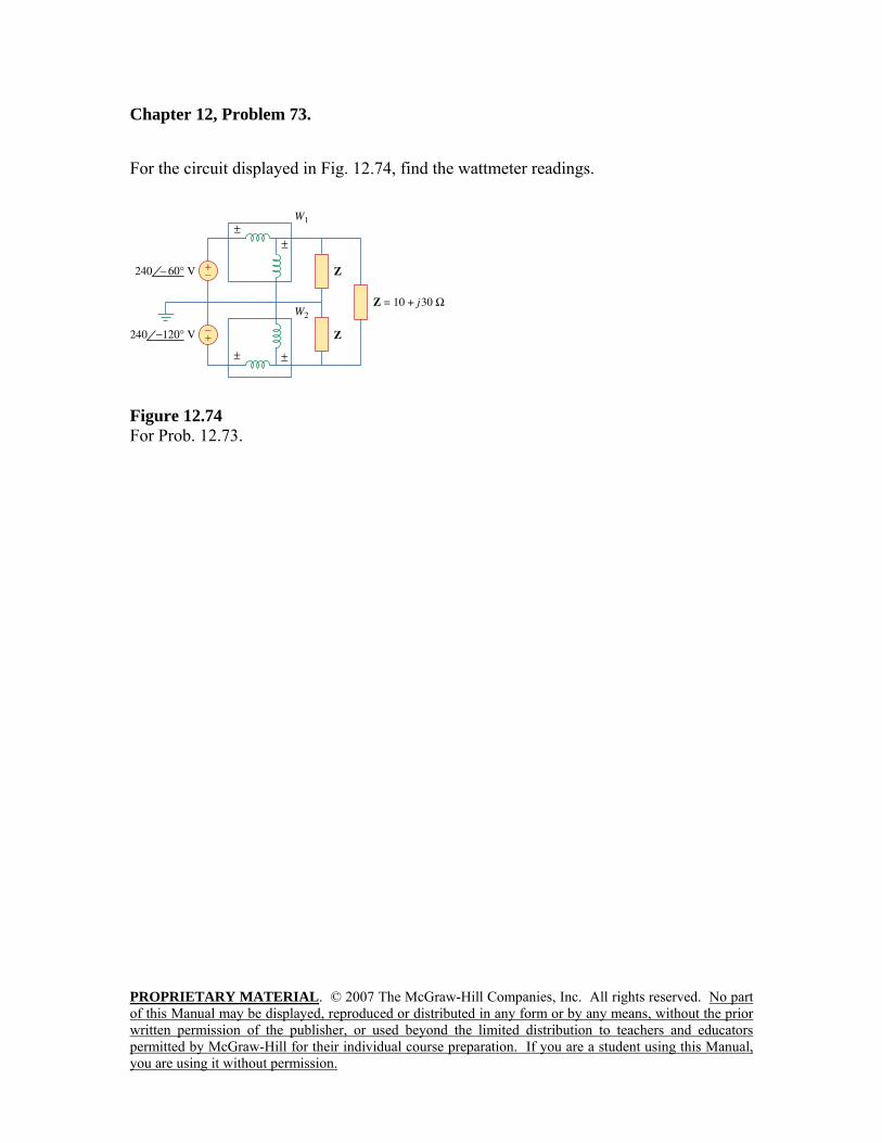
PROPRIETARY MATERIAL. © 2007 The McGraw-Hill Companies, Inc. All rights reserved. No part of this Manual may be displayed, reproduced or distributed in any form or by any means, without the prior written permission of the publisher, or used beyond the limited distribution to teachers and educators permitted by McGraw-Hill for their individual course preparation. If you are a student using this Manual, you are using it without permission.
Chapter 12, Problem 73. For the circuit displayed in Fig. 12.74, find the wattmeter readings.
Figure 12.74 For Prob. 12.73.
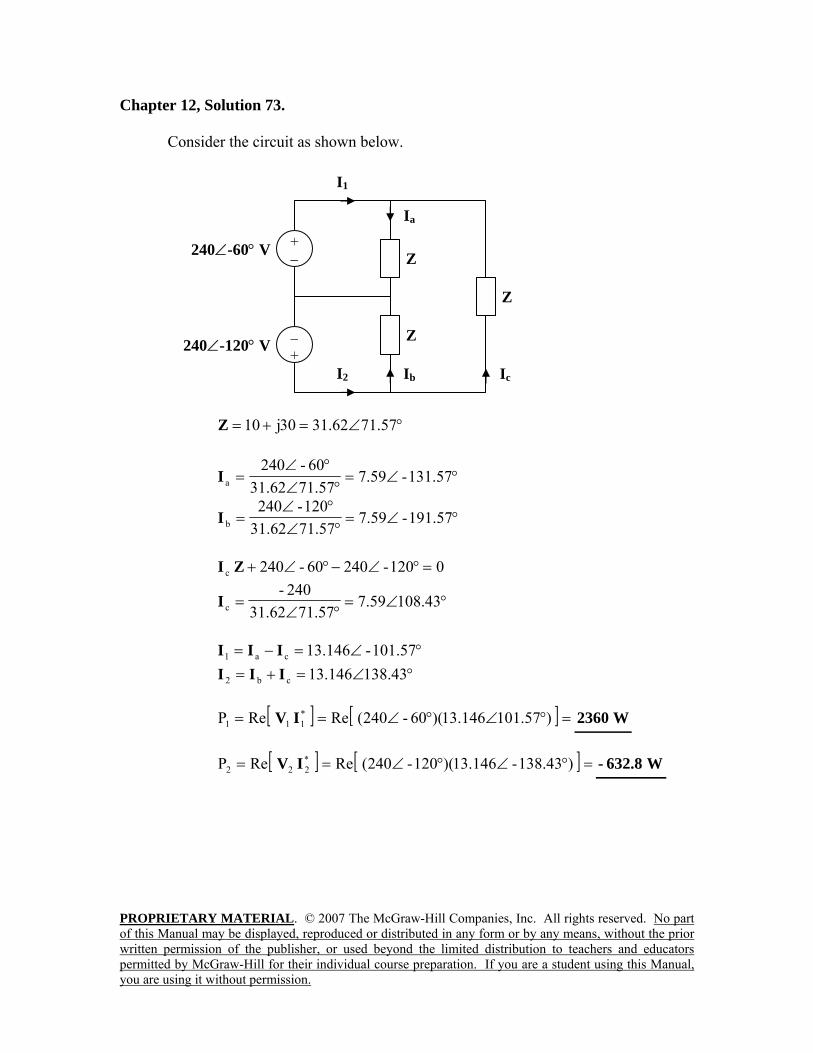
PROPRIETARY MATERIAL. © 2007 The McGraw-Hill Companies, Inc. All rights reserved. No part of this Manual may be displayed, reproduced or distributed in any form or by any means, without the prior written permission of the publisher, or used beyond the limited distribution to teachers and educators permitted by McGraw-Hill for their individual course preparation. If you are a student using this Manual, you are using it without permission.
Chapter 12, Solution 73. Consider the circuit as shown below.
°∠=+= 71.5762.3130j10Z
°∠=°∠
°∠= 131.57-59.7
71.5762.3160-240
aI
°∠=°∠°∠
= 191.57-59.771.5762.31120-240
bI
0120-24060-240c =°∠−°∠+ZI
°∠=°∠
= 108.4359.771.5731.62
240-cI
°∠=−= 101.57-146.13ca1 III °∠=+= 138.43146.13cb2 III
[ ] [ ] =°∠°∠== ).57101146.13)(60-240(ReReP *
111 IV W2360
[ ] [ ] =°∠°∠== )138.43-146.13)(120-240(ReReP *222 IV W8.632-
240∠-60° V + −
Ib
Ia
I1
− + 240∠-120° V
Ic
Z
Z
Z
I2
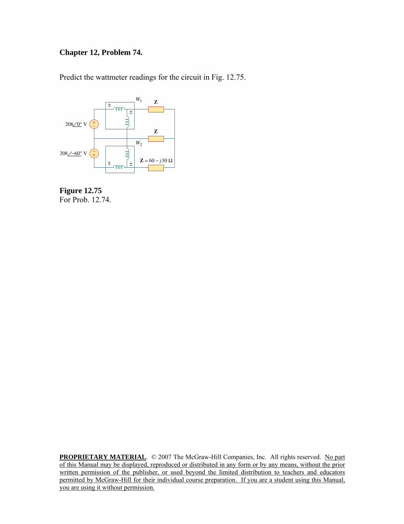
PROPRIETARY MATERIAL. © 2007 The McGraw-Hill Companies, Inc. All rights reserved. No part of this Manual may be displayed, reproduced or distributed in any form or by any means, without the prior written permission of the publisher, or used beyond the limited distribution to teachers and educators permitted by McGraw-Hill for their individual course preparation. If you are a student using this Manual, you are using it without permission.
Chapter 12, Problem 74. Predict the wattmeter readings for the circuit in Fig. 12.75.
Figure 12.75 For Prob. 12.74.
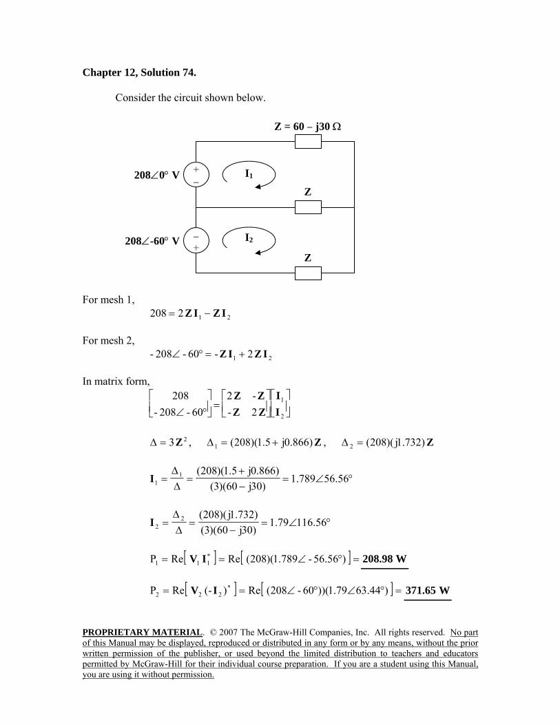
PROPRIETARY MATERIAL. © 2007 The McGraw-Hill Companies, Inc. All rights reserved. No part of this Manual may be displayed, reproduced or distributed in any form or by any means, without the prior written permission of the publisher, or used beyond the limited distribution to teachers and educators permitted by McGraw-Hill for their individual course preparation. If you are a student using this Manual, you are using it without permission.
Chapter 12, Solution 74. Consider the circuit shown below.
For mesh 1,
212208 IZIZ −= For mesh 2,
21 2-60-208- IZIZ +=°∠ In matrix form,
⎥⎦
⎤⎢⎣
⎡⎥⎦
⎤⎢⎣
⎡=⎥⎦
⎤⎢⎣
⎡°∠ 2
1
2--2
60-208-208
II
ZZZZ
23Z=∆ , Z)866.0j5.1)(208(1 +=∆ , Z)732.1j)(208(2 =∆
°∠=−+
=∆∆
= 56.56789.1)30j60)(3(
)866.0j5.1)(208(11I
°∠=−
=∆∆
= 116.5679.1)30j60)(3()732.1j)(208(2
2I
[ ] [ ] =°∠== )56.56-789.1)(208(ReReP *
111 IV W98.208
[ ] [ ] =°∠°∠== )63.4479.1))(60-208(Re)-(ReP *222 IV W65.371
Z = 60 − j30 Ω
Z
Z 208∠0° V +
− I1
I2208∠-60° V − +
PROPRIETARY MATERIAL. © 2007 The McGraw-Hill Companies, Inc. All rights reserved. No part of this Manual may be displayed, reproduced or distributed in any form or by any means, without the prior written permission of the publisher, or used beyond the limited distribution to teachers and educators permitted by McGraw-Hill for their individual course preparation. If you are a student using this Manual, you are using it without permission.
Chapter 12, Problem 75. A man has a body resistance of 600Ω . How much current flows through his ungrounded body: (a) when he touches the terminals of a 12-V autobattery? (b) when he sticks his finger into a 120-V light socket? Chapter 12, Solution 75.
(a) ===60012
RV
I mA20
(b) ===600120
RV
I mA200
Chapter 12, Problem 76.
Show that the RI 2 losses will be higher for a 120-V appliance than for a 240-V appliance if both have the same power rating. Chapter 12, Solution 76. If both appliances have the same power rating, P,
sVP
I =
For the 120-V appliance, 120
PI1 = .
For the 240-V appliance, 240P
I2 = .
Power loss =⎪⎩
⎪⎨
⎧
=appliance -V240 for the
240RP
appliance -V120 for the120
RP
RI2
2
2
2
2
Since 22 2401
1201
> , the losses in the 120-V appliance are higher.
PROPRIETARY MATERIAL. © 2007 The McGraw-Hill Companies, Inc. All rights reserved. No part of this Manual may be displayed, reproduced or distributed in any form or by any means, without the prior written permission of the publisher, or used beyond the limited distribution to teachers and educators permitted by McGraw-Hill for their individual course preparation. If you are a student using this Manual, you are using it without permission.
Chapter 12, Problem 77. A three-phase generator supplied 3.6 kVA at a power factor of 0.85 lagging. If 2500 W are delivered to the load and line losses are 80 W per phase, what are the losses in the generator? Chapter 12, Solution 77. lineloadTg PPPP −−= , 85.0pf =
But 3060pf3600cos3600PT =×=θ=
=−−= )80)(3(25003060Pg W320 Chapter 12, Problem 78. A three-phase 440-V, 51-kW, 60-kVA inductive load operates at 60 Hz and is wye-connected. It is desired to correct the power factor to 0.95 lagging. What value of capacitor should be placed in parallel with each load impedance? Chapter 12, Solution 78.
°=θ⎯→⎯==θ 79.3185.06051
cos 11
kVAR61.31)5268.0)(60(sinSQ 111 ==θ=
kW51PP 12 == °=θ⎯→⎯=θ 19.1895.0cos 22
kVA68.53cos
PS
2
22 =
θ=
kVAR759.16sinSQ 222 =θ=
kVAR851.14759.1661.3QQQ 21c =−=−=
For each load,
kVAR95.43
QQ c
1c ==
=π
=ω
= 221c
)440)(60)(2(4950
VQ
C F82.67 µ
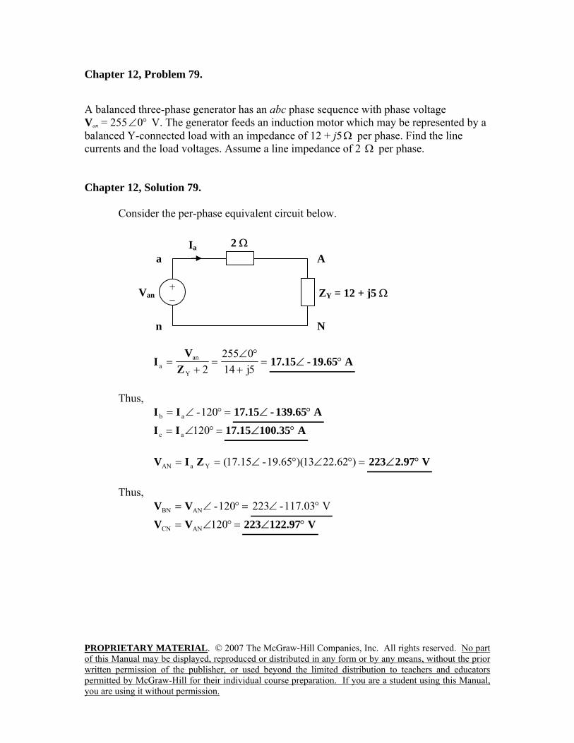
PROPRIETARY MATERIAL. © 2007 The McGraw-Hill Companies, Inc. All rights reserved. No part of this Manual may be displayed, reproduced or distributed in any form or by any means, without the prior written permission of the publisher, or used beyond the limited distribution to teachers and educators permitted by McGraw-Hill for their individual course preparation. If you are a student using this Manual, you are using it without permission.
Chapter 12, Problem 79. A balanced three-phase generator has an abc phase sequence with phase voltage Van = 255 °∠0 V. The generator feeds an induction motor which may be represented by a balanced Y-connected load with an impedance of 12 + j5Ω per phase. Find the line currents and the load voltages. Assume a line impedance of 2 Ω per phase. Chapter 12, Solution 79. Consider the per-phase equivalent circuit below.
=+
°∠=
+=
5j140255
2Y
ana Z
VI A19.65-15.17 °∠
Thus,
=°∠= 120-ab II A139.65-15.17 °∠ =°∠= 120ac II A100.3515.17 °∠
=°∠°∠== )22.6213)(19.65-15.17(YaAN ZIV V2.97223 °∠
Thus,
=°∠= 120-ANBN VV V117.03-223 °∠ =°∠= 120ANCN VV V122.97223 °∠
2 Ω
+ −
Van
A
N
Ia a
n
ZY = 12 + j5 Ω
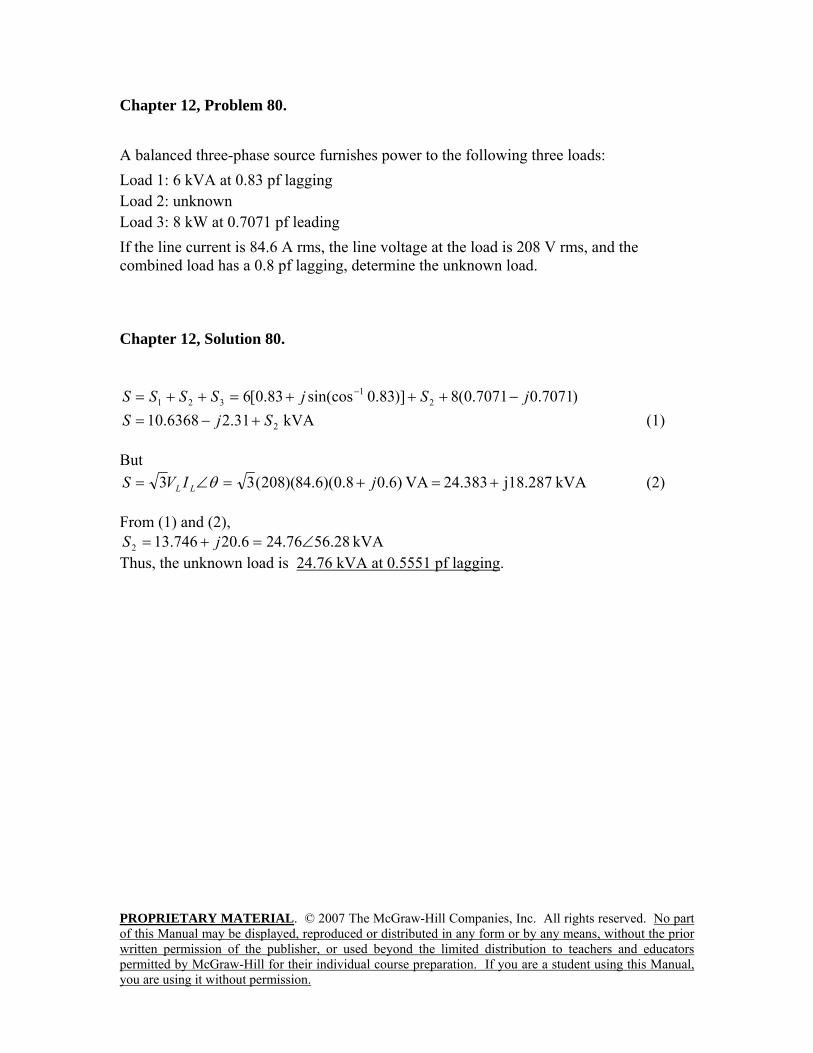
PROPRIETARY MATERIAL. © 2007 The McGraw-Hill Companies, Inc. All rights reserved. No part of this Manual may be displayed, reproduced or distributed in any form or by any means, without the prior written permission of the publisher, or used beyond the limited distribution to teachers and educators permitted by McGraw-Hill for their individual course preparation. If you are a student using this Manual, you are using it without permission.
Chapter 12, Problem 80. A balanced three-phase source furnishes power to the following three loads: Load 1: 6 kVA at 0.83 pf lagging Load 2: unknown Load 3: 8 kW at 0.7071 pf leading If the line current is 84.6 A rms, the line voltage at the load is 208 V rms, and the combined load has a 0.8 pf lagging, determine the unknown load. Chapter 12, Solution 80.
)7071.07071.0(8)]83.0sin(cos83.0[6 21
321 jSjSSSS −+++=++= − kVA 31.26368.10 2SjS +−= (1)
But
kVA j18.28724.383 VA )6.08.0)(6.84)(208(33 +=+=∠= jIVS LL θ (2) From (1) and (2),
kVA 28.5676.246.20746.132 ∠=+= jS Thus, the unknown load is 24.76 kVA at 0.5551 pf lagging.
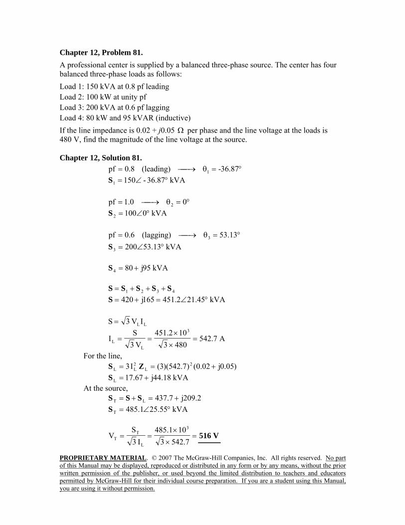
PROPRIETARY MATERIAL. © 2007 The McGraw-Hill Companies, Inc. All rights reserved. No part of this Manual may be displayed, reproduced or distributed in any form or by any means, without the prior written permission of the publisher, or used beyond the limited distribution to teachers and educators permitted by McGraw-Hill for their individual course preparation. If you are a student using this Manual, you are using it without permission.
Chapter 12, Problem 81. A professional center is supplied by a balanced three-phase source. The center has four balanced three-phase loads as follows: Load 1: 150 kVA at 0.8 pf leading Load 2: 100 kW at unity pf Load 3: 200 kVA at 0.6 pf lagging Load 4: 80 kW and 95 kVAR (inductive) If the line impedance is 0.02 + j0.05 Ω per phase and the line voltage at the loads is 480 V, find the magnitude of the line voltage at the source. Chapter 12, Solution 81. °=θ⎯→⎯= 87.36-(leading)8.0pf 1
kVA36.87-1501 °∠=S
°=θ⎯→⎯= 00.1pf 2 kVA01002 °∠=S
°=θ⎯→⎯= 13.53(lagging)6.0pf 3
kVA53.132003 °∠=S
kVA95j804 +=S
4321 SSSSS +++= kVA21.452.451165j420 °∠=+=S
LLIV3S =
A7.5424803102.451
V3S
I3
LL =
××
==
For the line, )05.0j02.0()7.542)(3(I3 2
L2LL +== ZS
kVA18.44j67.17L +=S At the source,
2.209j7.437LT +=+= SSS kVA25.551.485T °∠=S
=××
==7.5423
101.485I3
SV
3
L
TT V516
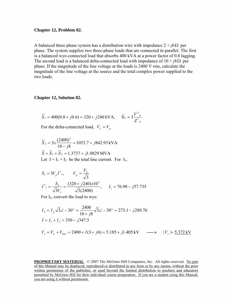
PROPRIETARY MATERIAL. © 2007 The McGraw-Hill Companies, Inc. All rights reserved. No part of this Manual may be displayed, reproduced or distributed in any form or by any means, without the prior written permission of the publisher, or used beyond the limited distribution to teachers and educators permitted by McGraw-Hill for their individual course preparation. If you are a student using this Manual, you are using it without permission.
Chapter 12, Problem 82.
A balanced three-phase system has a distribution wire with impedance 2 + j6Ω per phase. The system supplies two three-phase loads that are connected in parallel. The first is a balanced wye-connected load that absorbs 400 kVA at a power factor of 0.8 lagging. The second load is a balanced delta-connected load with impedance of 10 + j8Ω per phase. If the magnitude of the line voltage at the loads is 2400 V rms, calculate the magnitude of the line voltage at the source and the total complex power supplied to the two loads. Chapter 12, Solution 82.
p
p
ZVjjS *
2
21 3SkVA, 240320)6.08.0(400 =+=+=
For the delta-connected load, pL VV =
kVA 93.8427.1053810)2400(3
2
2 jj
xS +=−
=
MVA 0829.13737.121 jSSS +=+= Let I = I1 + I2 be the total line current. For I1,
3,3 1
*1
Lpp
VVIVS ==
735.5798.76,)2400(310)240320(
3 1
31
1* jIxj
VS
IL
−=+
==
For I2, convert the load to wye.
76.2891.273303810
24003032 jj
II oop −=−∠
+=−∠=
5.34735021 jIII −=+=
kV 372.5||kV 405.1185.5)63(2400 =⎯→⎯+=++=+= slineLs VjjIVVV
PROPRIETARY MATERIAL. © 2007 The McGraw-Hill Companies, Inc. All rights reserved. No part of this Manual may be displayed, reproduced or distributed in any form or by any means, without the prior written permission of the publisher, or used beyond the limited distribution to teachers and educators permitted by McGraw-Hill for their individual course preparation. If you are a student using this Manual, you are using it without permission.
Chapter 12, Problem 83.
A commercially available three-phase inductive motor operates at a full load of 120 hp (1 hp = 746 W) at 95 percent efficiency at a lagging power factor of 0.707. The motor is connected in parallel to a 80-kW balanced three-phase heater at unity power factor. If the magnitude of the line voltage is 480 V rms, calculate the line current. Chapter 12, Solution 83.
kVA 80SkVA, 135.60135.60)707.0707.0(95.0746120 21 =+=+= jjxxS
kVA 135.60135.14021 jSSS +=+=
A 42.1834803
1049.1523
||3||But 3
===⎯→⎯=x
xVSIIVS
LLLL
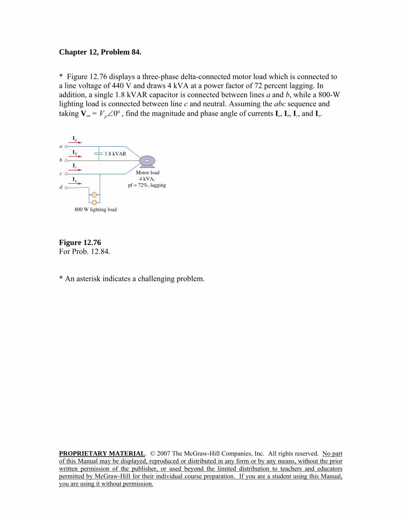
PROPRIETARY MATERIAL. © 2007 The McGraw-Hill Companies, Inc. All rights reserved. No part of this Manual may be displayed, reproduced or distributed in any form or by any means, without the prior written permission of the publisher, or used beyond the limited distribution to teachers and educators permitted by McGraw-Hill for their individual course preparation. If you are a student using this Manual, you are using it without permission.
Chapter 12, Problem 84. * Figure 12.76 displays a three-phase delta-connected motor load which is connected to a line voltage of 440 V and draws 4 kVA at a power factor of 72 percent lagging. In addition, a single 1.8 kVAR capacitor is connected between lines a and b, while a 800-W lighting load is connected between line c and neutral. Assuming the abc sequence and taking Van = °∠0pV , find the magnitude and phase angle of currents Ia, Ib, Ic, and In.
Figure 12.76 For Prob. 12.84. * An asterisk indicates a challenging problem.
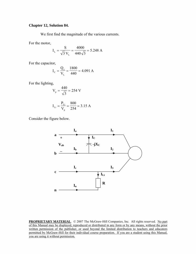
PROPRIETARY MATERIAL. © 2007 The McGraw-Hill Companies, Inc. All rights reserved. No part of this Manual may be displayed, reproduced or distributed in any form or by any means, without the prior written permission of the publisher, or used beyond the limited distribution to teachers and educators permitted by McGraw-Hill for their individual course preparation. If you are a student using this Manual, you are using it without permission.
Chapter 12, Solution 84. We first find the magnitude of the various currents. For the motor,
A248.53440
4000V3
SI
LL ===
For the capacitor,
A091.4440
1800VQ
IL
cC ===
For the lighting,
V2543
440Vp ==
A15.3254800
VP
Ip
LiLi ===
Consider the figure below.
-jXC
a IC
Ib
+
Vab
−
Ic
Ia
I2
I3
I1
ILi
b
c
n In
R
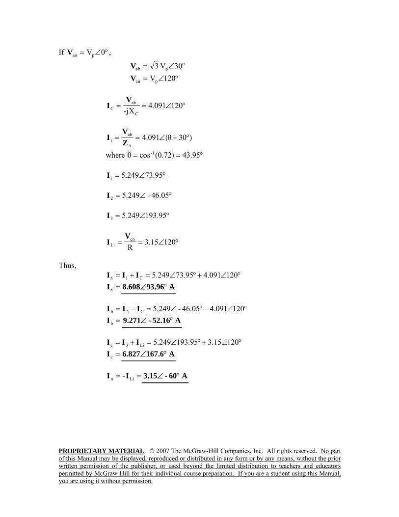
PROPRIETARY MATERIAL. © 2007 The McGraw-Hill Companies, Inc. All rights reserved. No part of this Manual may be displayed, reproduced or distributed in any form or by any means, without the prior written permission of the publisher, or used beyond the limited distribution to teachers and educators permitted by McGraw-Hill for their individual course preparation. If you are a student using this Manual, you are using it without permission.
If °∠= 0VpanV ,
°∠= 30V3 pabV °∠= 120VpcnV
°∠== 120091.4X-j C
abC
VI
)30(091.4ab1 °+θ∠==
∆ZV
I
where °==θ 95.43)72.0(cos-1
°∠= 73.95249.51I
°∠= 46.05-249.52I
°∠= 193.95249.53I
°∠== 12015.3R
cnLi
VI
Thus,
°∠+°∠=+= 120091.473.95249.5C1a III =aI A93.96608.8 °∠
°∠−°∠=−= 120091.446.05-249.5C2b III
=bI A52.16-271.9 °∠
°∠+°∠=+= 12015.3193.95249.5Li3c III =cI A167.6827.6 °∠
== Lin -II A60-15.3 °∠
PROPRIETARY MATERIAL. © 2007 The McGraw-Hill Companies, Inc. All rights reserved. No part of this Manual may be displayed, reproduced or distributed in any form or by any means, without the prior written permission of the publisher, or used beyond the limited distribution to teachers and educators permitted by McGraw-Hill for their individual course preparation. If you are a student using this Manual, you are using it without permission.
Chapter 12, Problem 85. Design a three-phase heater with suitable symmetric loads using wye-connected
pure resistance. Assume that the heater is supplied by a 240-V line voltage and is to give 27 kW of heat. Chapter 12, Solution 85. Let RZY =
V56.1383
2403
VV L
p ===
RV
kW92
27IVP
2p
pp ====
Ω=== 133.29000
)56.138(P
VR
22p
Thus, =YZ Ω133.2
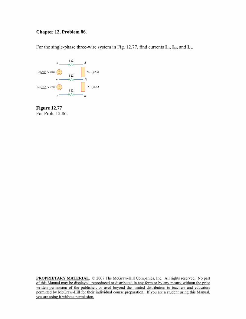
PROPRIETARY MATERIAL. © 2007 The McGraw-Hill Companies, Inc. All rights reserved. No part of this Manual may be displayed, reproduced or distributed in any form or by any means, without the prior written permission of the publisher, or used beyond the limited distribution to teachers and educators permitted by McGraw-Hill for their individual course preparation. If you are a student using this Manual, you are using it without permission.
Chapter 12, Problem 86. For the single-phase three-wire system in Fig. 12.77, find currents IaA, IbB, and InN.
Figure 12.77 For Prob. 12.86.
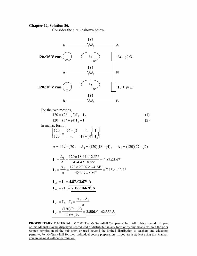
PROPRIETARY MATERIAL. © 2007 The McGraw-Hill Companies, Inc. All rights reserved. No part of this Manual may be displayed, reproduced or distributed in any form or by any means, without the prior written permission of the publisher, or used beyond the limited distribution to teachers and educators permitted by McGraw-Hill for their individual course preparation. If you are a student using this Manual, you are using it without permission.
Chapter 12, Solution 86. Consider the circuit shown below.
For the two meshes,
21)2j26(120 II −−= (1)
12)4j17(120 II −+= (2) In matrix form,
⎥⎦
⎤⎢⎣
⎡⎥⎦
⎤⎢⎣
⎡+
−=⎥⎦
⎤⎢⎣
⎡
2
1
4j171-1-2j26
120120
II
70j449 +=∆ , )4j18)(120(1 +=∆ , )2j27)(120(2 −=∆
°∠=°∠°∠×
=∆∆
= 3.6787.48.8642.454
12.5344.1812011I
°∠=°∠
°∠×=
∆∆
= 13.1-15.78.8642.454
4.24-07.2712022I
== 1aA II A3.6787.4 °∠ == 2bB -II A166.915.7 °∠
∆∆−∆
=−= 1212nN III
=+−
=70j449
)6j9)(120(nNI A42.55-856.2 °∠
1 Ω
1 Ω
120∠0° V rms + −
a
1 Ω
24 – j2 Ω
15 + j4 Ω120∠0° V rms + −
I2
I1
n
b
A
N
B
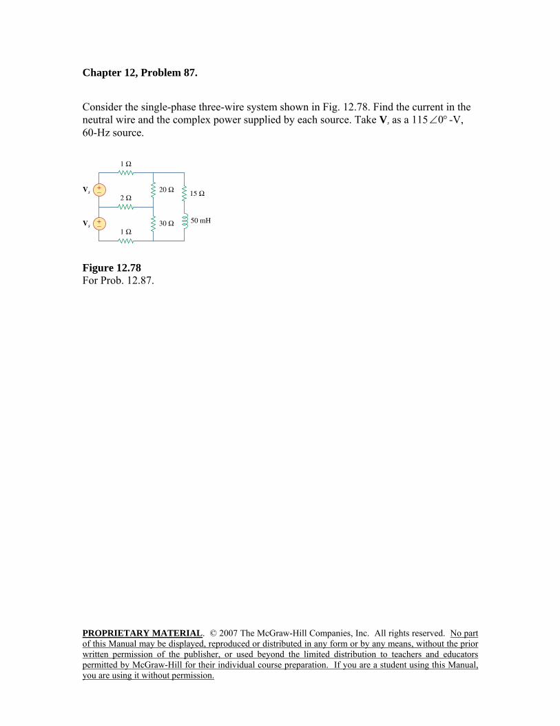
PROPRIETARY MATERIAL. © 2007 The McGraw-Hill Companies, Inc. All rights reserved. No part of this Manual may be displayed, reproduced or distributed in any form or by any means, without the prior written permission of the publisher, or used beyond the limited distribution to teachers and educators permitted by McGraw-Hill for their individual course preparation. If you are a student using this Manual, you are using it without permission.
Chapter 12, Problem 87. Consider the single-phase three-wire system shown in Fig. 12.78. Find the current in the neutral wire and the complex power supplied by each source. Take Vs as a 115 °∠0 -V, 60-Hz source.
Figure 12.78 For Prob. 12.87.

PROPRIETARY MATERIAL. © 2007 The McGraw-Hill Companies, Inc. All rights reserved. No part of this Manual may be displayed, reproduced or distributed in any form or by any means, without the prior written permission of the publisher, or used beyond the limited distribution to teachers and educators permitted by McGraw-Hill for their individual course preparation. If you are a student using this Manual, you are using it without permission.
Chapter 12, Solution 87. 85.18j)5010)(60)(2(jLjmH50L 3- =π=ω⎯→⎯= Consider the circuit below.
Applying KVl to the three meshes, we obtain 11520223 321 =−− III (1) 11530332- 321 =−+ III (2)
0)85.18j65(3020- 321 =++− III (3) In matrix form,
⎥⎥⎥
⎦
⎤
⎢⎢⎢
⎣
⎡=
⎥⎥⎥
⎦
⎤
⎢⎢⎢
⎣
⎡
⎥⎥⎥
⎦
⎤
⎢⎢⎢
⎣
⎡
+ 0115115
j18.856530-20-30-332-20-2-23
3
2
1
III
232,14j775,12 +=∆ , )8.659j1975)(115(1 +=∆
)3.471j1825)(115(2 +=∆ , )1450)(115(3 =∆
°∠=°∠°∠×
=∆∆
= 29.62-52.1248.0919214
47.18208211511I
°∠=°∠
°∠×=
∆∆
= 33.61-33.1148.0919124
14.489.188411522I
=+
−=
∆∆−∆
=−=75.231,14j775,12
)5.188j-150)(115(1212n III A176.6-448.1 °∠
=°∠== )29.6252.12)(115(IVS *
111 VA6.711j1252 +
=°∠== )33.6133.1)(115(*222 IVS VA2.721j1085 +
1 Ω
1 Ω
+ −
2 Ω
+ −
I2
I120 Ω
15 + j18.85 Ω
30 Ω
115 V
115 V