Embed Size (px)
Citation preview
Water Sensitive Urban Design Technical ManualGreater Adelaide Region
December 2010
Sedimentation Basins
Chapter 12
Water Sensitive Urban Design – Greater Adelaide Region Technical Manual – December 2010
Department of Planning and Local Government Roma Mitchell House, 136 North Terrace, Adelaide SA 5000 GPO Box 1815, Adelaide SA 5001 phone: (08) 8303 0600 The Water Sensitive Urban Design documents can be downloaded from the following website: www.planning.sa.gov.au/go/wsud © Government of South Australia
ISBN 978-1-876702-99-1
Preferred way to cite this publication
Department of Planning and Local Government, 2010, Water Sensitive Urban Design Technical Manual for the Greater Adelaide Region, Government of South Australia, Adelaide Disclaimer
Every effort has been made by the authors and the sponsoring organisations to verify that the methods and recommendations contained in this document are appropriate for Greater Adelaide Region conditions.
Notwithstanding these efforts, no warranty or guarantee, express, implied or statutory, is made as to the accuracy, reliability, suitability or results of the methods or recommendations.
The authors and sponsoring organisations shall have no liability or responsibility to the user or any other person or entity with respect to any liability, loss or damage caused or alleged to be caused, directly or indirectly, by the adoption and use of the methods and recommendations of the document, including, but not limited to, any interruption of service, loss of business or anticipatory profits, or consequential damages resulting from the use of the document. Use of the document requires professional interpretation and judgment.
Appropriate design procedures and assessment must be applied to suit the particular circumstances under consideration.
Sedimentation Basins 12
Water Sensitive Urban Design – Greater Adelaide Region Technical Manual – December 2010
Water Sensitive Urban Design Water Sensitive Urban Design (WSUD) is an approach to urban planning and design that integrates the management of the total water cycle into the urban development process. It includes:
Integrated management of groundwater, surface runoff (including stormwater), drinking water and wastewater to protect water related environmental, recreational and cultural values;
Storage, treatment and beneficial use of runoff;
Treatment and reuse of wastewater;
Using vegetation for treatment purposes, water efficient landscaping and enhancing biodiversity; and
Utilising water saving measures within and outside domestic, commercial, industrial and institutional premises to minimise requirements for drinking and non drinking water supplies.
Therefore, WSUD incorporates all water resources, including surface water, groundwater, urban and roof runoff and wastewater.
12 Sedimentation Basins
Water Sensitive Urban Design – Greater Adelaide Region Technical Manual – December 2010
Acknowledgments Funding for preparation of the Water Sensitive Urban Design Technical Manual for the Greater Adelaide Region was provided by the Australian Government and the South Australian Government with support from the Local Government Association (SA).
The project partners gratefully acknowledge all persons and organisations that provided comments, suggestions and photographic material.
In particular, it is acknowledged that material was sourced and adapted from existing documents locally and interstate.
Overall Project Management
Christine Lloyd (Department of Planning and Local Government)
Steering Committee
A group of local government, industry and agency representatives provided input and feedback during preparation of the Technical Manual. This group included representatives from:
▪ Adelaide and Mt Lofty Ranges Natural Resources Management Board;
▪ Australian Water Association (AWA);
▪ Department for Transport, Energy and Infrastructure (DTEI);
▪ Department of Water, Land and Biodiversity Conservation (DWLBC);
▪ Environment Protection Authority (EPA);
▪ Housing Industry Association (HIA);
▪ Local Government Association (LGA);
▪ Department of Planning and Local Government (DPLG);
▪ South Australian Murray-Darling Basin Natural Resources Management Board;
▪ South Australian Water Corporation;
▪ Stormwater Industry Association (SIA); and
▪ Urban Development Institute of Australia (UDIA).
Technical Sub Committee
A technical sub committee, chaired by Dr David Kemp (DTEI), reviewed the technical and scientific aspects of the Technical Manual during development. This group included representatives from:
▪ Adelaide and Mt Lofty Ranges Natural Resources Management Board;
▪ City of Salisbury;
▪ Department for Transport, Energy and Infrastructure (DTEI);
▪ Department of Health;
▪ Department of Water, Land and Biodiversity Conservation;
▪ Department of Planning and Local Government; and
▪ Urban Development Institute of Australia.
From July 2010, DWLBC was disbanded and its responsibilities allocated to the newly created Department For Water (DFW) and the Department of Environment and Natural Resources (DENR). Specialist consultant team
Dr Kylie Hyde (Australian Water Environments) was the project manager for a consultant team engaged for its specialist expertise and experience in water resources management, to prepare the Technical Manual.
This team comprised Australian Water Environments, the University of South Australia, Wayne Phillips and Associates and QED Pty Ltd.
Beecham and Associates prepared Chapter 16 of the Technical Manual.
Sedimentation Basins 12
Water Sensitive Urban Design – Greater Adelaide Region Technical Manual – December 2010
Contents Chapter 12 Sedimentation Basins.............................................................................. 12-1
12.1 Overview .............................................................................................................. 12-1
12.2 Legislative Requirements and Approvals......................................................... 12-6
12.3 Design Considerations and Process................................................................... 12-8
12.4 Design Tools....................................................................................................... 12-15
12.5 Construction Process ......................................................................................... 12-16
12.6 Maintenance Requirements .............................................................................. 12-18
12.7 Useful Resources and Further Information .................................................... 12-20
12.8 References........................................................................................................... 12-22
Figures Figure 12.1 Elements of a Sedimentation Basin ....................................................... 12-2
Figure 12.2 Cross Section of a Sedimentation Basin................................................ 12-3
Figure 12.3 Sedimentation Basin Area vs Design Discharges for Varying Capture Efficiencies of 125 m Sediment Size..................................... 12-5
Figure 12.4 Brookes Bridge Sedimentation Basin.................................................. 12-11
Appendices Appendix A Checklists

Sedimentation Basins 12
12-1 Water Sensitive Urban Design – Greater Adelaide Region Technical Manual – December 2010
Chapter 12 Sedimentation Basins 12.1 Overview As detailed in Chapter 1, there are many different WSUD measures which together form a ’tool kit‘ from which individual measures can be selected as part of a specific design response suiting the characteristics of any development (or redevelopment). Sedimentation basins are one of those measures.
This chapter of the Technical Manual for the Greater Adelaide Region is aimed at providing an overview of sedimentation basins and how they can be utilised to assist in achieving the objectives and targets of WSUD. Further detailed design information can be obtained from the references included in the Useful Resources and Further Information section (see Section 12.7).
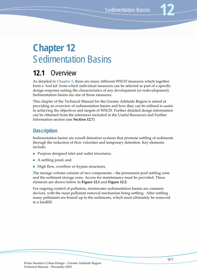
Description Sedimentation basins are runoff detention systems that promote settling of sediments through the reduction of flow velocities and temporary detention. Key elements include:
Purpose designed inlet and outlet structures;
A settling pond; and
High flow, overflow or bypass structures.
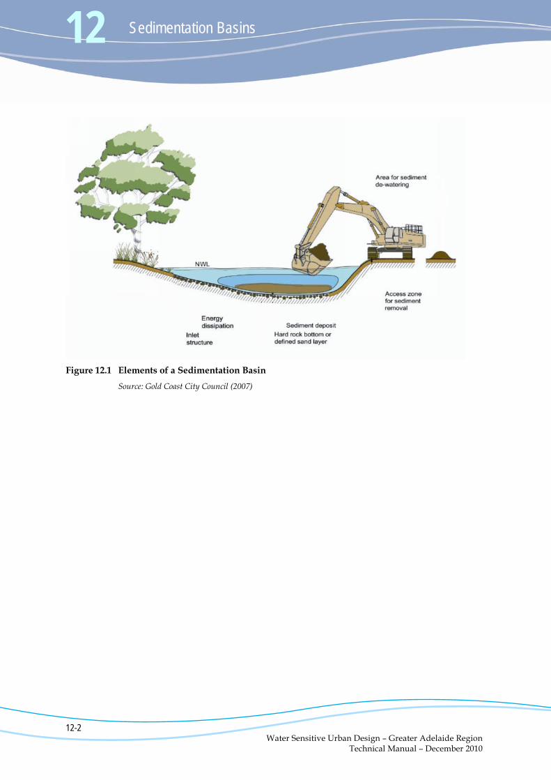
The storage volume consists of two components – the permanent pool settling zone and the sediment storage zone. Access for maintenance must be provided. These elements are shown below in Figure 12.1 and Figure 12.2.
For ongoing control of pollution, stormwater sedimentation basins are common devices, with the main pollutant removal mechanism being settling. After settling many pollutants are bound up in the sediments, which must ultimately be removed to a landfill.
12 Sedimentation Basins
12-2 Water Sensitive Urban Design – Greater Adelaide Region Technical Manual – December 2010
Figure 12.1 Elements of a Sedimentation Basin
Source: Gold Coast City Council (2007)
Sedimentation Basins 12
12-3 Water Sensitive Urban Design – Greater Adelaide Region Technical Manual – December 2010
Figure 12.2 Cross Section of a Sedimentation Basin
Source: Gold Coast City Council (2007)
12 Sedimentation Basins
12-4 Water Sensitive Urban Design – Greater Adelaide Region Technical Manual – December 2010
Purpose The main function of sedimentation systems is water quality treatment.
Reducing sediment loads is an important component of improving the quality of runoff. Sedimentation basins have two keys roles:
The primary function of a sedimentation basin is to target coarse to medium sized sediment (i.e. 125 μm1 or larger) prior to waters entering the downstream treatment systems (e.g. macrophyte zone of a constructed wetland or a bioretention basin). This ensures that the vegetation in the downstream treatment system is not smothered by sediment and allows downstream treatment systems to target finer particulates, nutrients and other pollutants.
The second function is the control or regulation of flows entering the downstream treatment system during ‘design operation’ and ‘above design’ conditions. The outlet structures from the sedimentation basin are designed such that flows up to the ‘design operation flow’ (typically the 1 year ARI) enter the downstream treatment system, whereas ‘above design flows’ are bypassed around the downstream treatment system. In providing this function, the sedimentation basin protects the vegetation in the downstream treatment system against scour during high flows. The configuration of outlet structures within sedimentation basins depends on the design flows entering the basin and the type of treatment systems located downstream.
Additional flood control can be achieved by incorporating a dedicated flood storage volume in the overall design.
Scale and Application Sedimentation basins can take various forms (at a range of scales). They can be used as permanent systems integrated into an urban design, or temporary measures to control sediment discharge during construction.
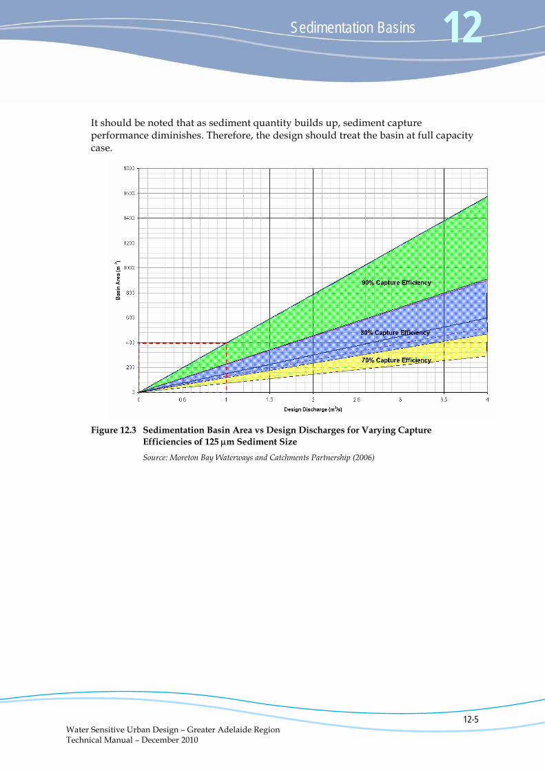
Removal Efficiencies Figure 12.3 shows the relationship between the required sedimentation basin area and design discharge for 125 m sediment capture efficiencies of 70%, 80% and 90% using a typical shape configuration. This curve can be utilised to estimate the size of the sedimentation basin required.
1 μm refers to micrometres, also called microns.
Sedimentation Basins 12
12-5 Water Sensitive Urban Design – Greater Adelaide Region Technical Manual – December 2010
It should be noted that as sediment quantity builds up, sediment capture performance diminishes. Therefore, the design should treat the basin at full capacity case.
Figure 12.3 Sedimentation Basin Area vs Design Discharges for Varying Capture
Efficiencies of 125 m Sediment Size
Source: Moreton Bay Waterways and Catchments Partnership (2006)
12 Sedimentation Basins
12-6 Water Sensitive Urban Design – Greater Adelaide Region Technical Manual – December 2010
12.2 Legislative Requirements and Approvals Before undertaking a concept design of a sedimentation basin it is important to check whether there are any planning regulations, building regulations or local health requirements that apply to sedimentation basins in your area.
The legislation which is most applicable to the design and construction of sedimentation basins includes:
Development Act 1993 and Development Regulations 2008; and
Environment Protection Act 1993.
Development Act 1993 Installing a sedimentation basin will generally be part of a larger development, however whenever a sedimentation basin is planned, it is advised that the council be contacted to determine whether development approval is required under the Development Act 1993.
Environment Protection Act 1993 Any development, including the construction of a sedimentation basin, has the potential for environmental impact, which can result from vegetation removal, stormwater management and construction processes. There is a general environmental duty, as required by Section 25 of the Environment Protection Act 1993, to take all reasonable and practical measures to ensure that the activities on the whole site, including during construction, do not pollute the environment in a way which causes or may cause environmental harm.
Aspects of the Environment Protection Act 1993 which must be considered when planning on constructing a sedimentation basin are discussed below.
Water Quality
Water quality in South Australia is protected using the Environment Protection Act 1993 and the associated Environment Protection (Water Quality) Policy 2003. The principal aim of the Water Quality Policy is to achieve the sustainable management of waters by protecting or enhancing water quality while allowing economic and social development. In particular, the policy seeks to:
Ensure that pollution from both diffuse and point sources does not reduce water quality; and
Promote best practice environmental management.
Sedimentation Basins 12
12-7 Water Sensitive Urban Design – Greater Adelaide Region Technical Manual – December 2010
Through inappropriate management practices, construction sites can be major contributors of sediment, suspended solids, concrete wash, building materials and wastes to the stormwater system. Consequently, all precautions need to be taken on a site to minimise potential for environmental impact during construction of a sedimentation basin.
It should also be noted that there is a high potential for anoxic conditions to occur in sedimentation basins due to high organic loading (in standing water). Therefore, public access to sedimentation basins should be restricted.
Noise
The issue of noise has the potential to cause nuisance during any construction works of sedimentation basins. The noise level at the nearest sensitive receiver should be at least 5 dB(A) below the Environment Protection (Industrial Noise) Policy 1994 allowable noise level when measured and adjusted in accordance with that policy. Reference should be made to the EPA Information Sheets on Construction Noise and Environmental Noise respectively and to assist in complying with this policy (see Section 12.7).
Air Quality
Air quality may be affected during the construction of a sedimentation basin. Dust generated by machinery and vehicular movement during site works, and any open stockpiling of soil or building materials at a site, must be managed to ensure that dust generation does not become a nuisance off site.
Waste
Any wastes arising from excavation and construction work on a site should be stored, handled and disposed of in accordance with the requirements of the Environment Protection Act 1993. For example, during construction, all wastes must be contained in a covered waste bin (where possible) or alternatively removed from the site on a daily basis for appropriate off-site disposal. Guidance can be found in the EPA Handbook for Pollution Avoidance on Building Sites (see Section 12.7).
12 Sedimentation Basins
12-8 Water Sensitive Urban Design – Greater Adelaide Region Technical Manual – December 2010
12.3 Design Considerations and Process The general design process for sedimentation basins includes the following key steps:
Site analysis (including determining any site constraints);
Determine the design objectives and targets;
Meet with council and other relevant authorities;
Concept design:
- Topographical survey of the site - Selecting a target sediment size - Estimating design flows - Landscaping opportunities - Determining the size and shape of the sedimentation basin - Provision of access for maintenance - Calculating the sediment storage volume - Determining the base material requirements of the basin - Producing cross sections of the basin;
Approvals process:
- Local government - Environment Protection Authority - Natural Resources Management Board - Department of Water Land and Biodiversity Conservation;
Detailed design, including designing structures:
- Hydraulic structures - Outlet pit - Discharge control structure - Overflow structure;
Check design objectives;
Vegetation specification;
Develop a maintenance plan.
It should be noted that not all of the steps detailed above will be required for each sedimentation basin design.
A number of the design process elements are discussed briefly below.
Detailed sedimentation basin design process information is contained in various publications (see Section 12.7 – Useful Resources and Further Information) and is not presented in this chapter. The information obtained from interstate references should be adapted for the Greater Adelaide Region.
Sedimentation Basins 12
12-9 Water Sensitive Urban Design – Greater Adelaide Region Technical Manual – December 2010
Site Analysis WSUD responds to site conditions and land capability and cannot be applied in a standard way. Careful assessment and interpretation of site conditions is therefore a fundamental part of designing a development that effectively incorporates WSUD.
Factors which should be considered when undertaking a site suitability assessment include:
Open space and landscape;
Flora and fauna;
Services;
Catchment characteristics;
Potential site contamination;
Soil properties; and
Topography of the site.
Further information on site analysis can be found in Chapter 3 of the Technical Manual.
Objectives and Targets Before the commencement of the design process, the objectives and targets for the sedimentation basin should be established. Objectives include environmental benefits (such as water quality improvement, detention and erosion control), habitat value (enhancing biodiversity and conservation), or aesthetic and recreational values.
If the objectives for designing a sedimentation basin are clearly defined, the design task is simplified.
Further information on objectives and targets can be obtained from Chapter 3 of the Technical Manual.
Meet with Local Council Before designing or installing a sedimentation basin, it is important to check whether there are any planning regulations, building regulations or local health requirements that apply to the construction and operation of sedimentation basins in your area. A meeting with your local development assessment officer at council is therefore recommended.
The council will also be able to advise whether:
Development approval is required and, if so, what information should be provided with the development application;
12 Sedimentation Basins
12-10 Water Sensitive Urban Design – Greater Adelaide Region Technical Manual – December 2010
Any other approving authorities should be consulted; and
Any specific council requirements need to be taken into consideration.
Land and asset ownership issues are key considerations prior to construction of a WSUD measure, including sedimentation basins. A proposed design should clearly identify the asset owner and who is responsible for maintenance, and this aspect should also be discussed during a meeting with the local council.
Concept Design
Target Sediment Size
Selecting a target sediment size is an important part of the design process. As a pre-treatment facility, it is recommended that particles of 125 μm or larger be the selected target sediment size because analysis of typical catchment sediment loads suggest that between 50-80% of suspended solids conveyed in urban stormwater are 125 μm or larger. Almost all sediment bed loads are larger than this target sediment size.
Removal of particles < 125 μm is best undertaken by treatment measures other than sedimentation basins (e.g. constructed wetlands and bioretention systems).
Landscaping Opportunities
Sedimentation basins are often located within public open space areas and can be landscaped to create a focal point for passive recreation. Landscape design can also include pathways and information signs.
However, the design must also consider access to the sedimentation basin and associated infrastructure for maintenance purposes as discussed below.
Estimating Design Flows
A range of hydrologic methods can be applied to estimate design flows for sedimentation basins. With typical catchment areas being relatively small, the rational method design procedure is considered to be the most suitable method. For sedimentation basins with large catchments (> 50 Ha), a runoff routing model should be used to estimate design flows.
Sizing a Sedimentation Basin
The required size of a sedimentation basin is calculated to match the settling velocity of a target sediment size with a design flow (typically 1 year ARI).
While a basin must be of an adequate size for capturing the target sediment size, it should not be grossly oversized. Conversely, a sedimentation basin that is too small could have limited effectiveness, resulting in sediment smothering of downstream treatment measures.
Sedimentation Basins 12
12-11 Water Sensitive Urban Design – Greater Adelaide Region Technical Manual – December 2010
Where the sedimentation basin forms part of a treatment train and when available space is constrained, it is important to ensure that the size of the sedimentation basin (i.e. inlet zone of a constructed wetland) is not reduced. This ensures that the coarse sediments are effectively trapped and prevented from smothering the downstream treatment system. If the site constrains the total area available for the treatment train, the downstream treatment system should be reduced accordingly.
A further consideration in the design of a sedimentation basin is the provision of adequate storage for settled sediment to prevent the need for frequent desilting. Basin desilting is desirable once every five years and is generally triggered when sediment accumulates to half the basin depth. The volume of accumulated sediment can be estimated from regular monitoring of sediment levels with a measuring post and reference against the top water level.
A developing catchment can be expected to discharge between 50 m3/ha and 200 m3/ha of sediment each year. In a developed catchment, the annual sediment export is generally one to two orders of magnitude lower with an expected mean annual rate of 1.60 m3/ha (Melbourne Water 2005a).
It should be noted that bed load should also be considered when calculating the total expected sediment load.
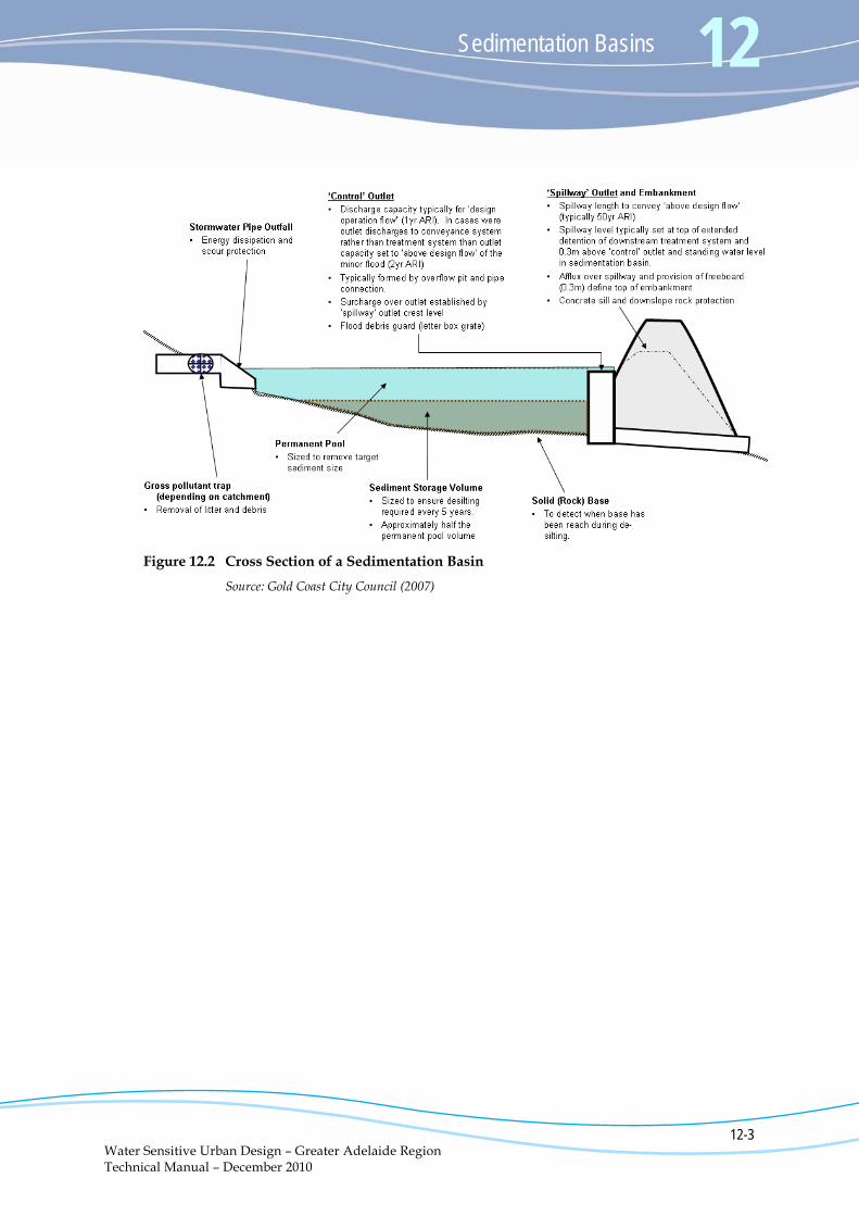
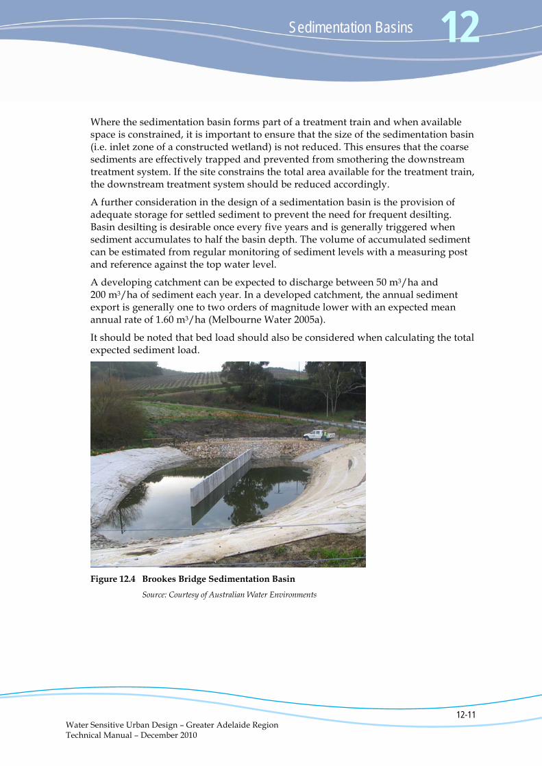
Figure 12.4 Brookes Bridge Sedimentation Basin
Source: Courtesy of Australian Water Environments
12 Sedimentation Basins
12-12 Water Sensitive Urban Design – Greater Adelaide Region Technical Manual – December 2010
Access for Maintenance
Accessibility for maintenance is an important design consideration. If an excavator is able to reach all parts of the sedimentation basin from the top of the batter then an access ramp may not be required. However, an access track around the perimeter of the sedimentation basin will be required and will affect the overall landscape design.
If sediment collection requires earthmoving equipment to enter the sedimentation basin, a stable ramp will be required into the base of the sedimentation basin (maximum slope 1:10).
In terms of configuration, the basin should have a maximum width of 14 metres to allow access to the maintenance plant, unless approval is provided for long reach excavators or the construction of access ramps into the basin (Melbourne Water 2005a).
Maintenance of sedimentation basins is discussed further in Section 12.6.
Base Material of the Basin
Sedimentation basins are required to detain water (to enable settling of the sediments) and therefore the base must be of a suitable material to retain water (e.g. clay), typically overlain with a hard (e.g. rock) bottom to enable maintenance (see below). A lining for the sedimentation basin is particularly relevant where there are potential adverse impacts on the groundwater system.
It should be noted that wet sedimentation basins can be problematic to maintain and poor water quality (and odour and mosquito problems) can be an issue. An ideal scenario is for the sedimentation basin to drain fully over time.
Detailed Design – Outlet Structure An outlet structure of a sedimentation basin can be configured in many ways and is generally dependant on the design flow entering the basin and the type of stormwater treatment system or conveyance system downstream of its outlet.
For example, a sedimentation basin forming the inlet zone of a constructed wetland would typically include an overflow pit located within the sedimentation basin with one or more pipes connecting the sedimentation basin to an open water zone at the head of the wetland macrophyte zone.
A sedimentation basin pre-treating runoff entering a bioretention basin would typically use a weir outlet to keep flows at surface, to enable the flow to discharge onto the surface of the bioretention filter media.
In most cases, the outlet design of a sedimentation basin will consist of a ‘control’ outlet structure and a ‘spillway’ outlet structure:
Sedimentation Basins 12
12-13 Water Sensitive Urban Design – Greater Adelaide Region Technical Manual – December 2010
The ‘control’ outlet can be either an overflow pit/pipe or weir which delivers flows up to the ‘design operation flow’ to the downstream treatment system(s);
The ‘spillway’ outlet structure ensures that flows above the ‘design operation flow’ are discharged to a bypass channel or conveyance system; and
The ‘spillway’ bypass weir level is set above the ‘control’ outlet structure and typically at the top of the extended detention depth of the downstream treatment system.
Where the sedimentation basin discharges to a conveyance system (e.g. swale or piped system), a ‘control’ outlet may not be required and one outlet can be designed to allow discharge of all flows including flood flows.
The outlets from sedimentation basins are to be designed such that access to the outlet does not require a water vessel (e.g. boat).
If controlled flow discharge or an upstream bypass diversion system is not provided, a means should be provided for emptying the sedimentation basin to facilitate drying and emptying.
Vegetation Specification The role of vegetation in sedimentation basin design is to provide scour and erosion protection to the basin batters. In addition, dense planting of the littoral zones will restrict public access to the open water, reducing the potential safety risks posed by water bodies. The planting should ensure that 70-80% cover is achieved after two growing seasons (two years). Terrestrial planting may also be recommended to screen areas and provide a barrier to steeper batters.
Plant species should be selected based on:
The water level regime;
Soil types of the region; and
The life histories, physiological and structural characteristics, natural distribution, and community groups of the plants.
Care needs to be taken in species selection to ensure vegetative growth will not spread to cover the deeper water zones. Similarly, floating or submerged macrophytes should be avoided. A sedimentation basin should primarily consist of open water to allow for settling of only the target sediments (e.g. > 125 μm) and to permit periodic sediment removal.
Plant species selection and placement should integrate with the surrounding landscape and community character, as well as providing or enhancing local habitat.
A vegetation specification therefore needs to be developed and it is recommended that this be undertaken in consultation with a landscape architect.
12 Sedimentation Basins
12-14 Water Sensitive Urban Design – Greater Adelaide Region Technical Manual – December 2010
It should be noted that the timing of planting is critical to optimum establishment of plants. Poor timing can result in excessive erosion, plant losses and additional costs.
Maintenance Maintenance access to all sediment removal areas must be ensured.
Hard stand areas must be provided adjacent to the inlet zone to allow for the maintenance and cleanout of this zone. The hard stand should be at least 3 metres wide and designed to be capable of supporting a 20 tonne excavation plant. Multiple areas should be considered where the pond is greater than 7 metres wide. Adequate space for dewatering should also be provided (Melbourne Water 2005a).
A method for identifying the base of the sedimentation basin when cleaning out collected sediment (e.g. concrete base, rock or identifiable sand) should be provided.
A maintenance plan for the sedimentation basin should be developed as part of the design process, as discussed in Section 12.6.
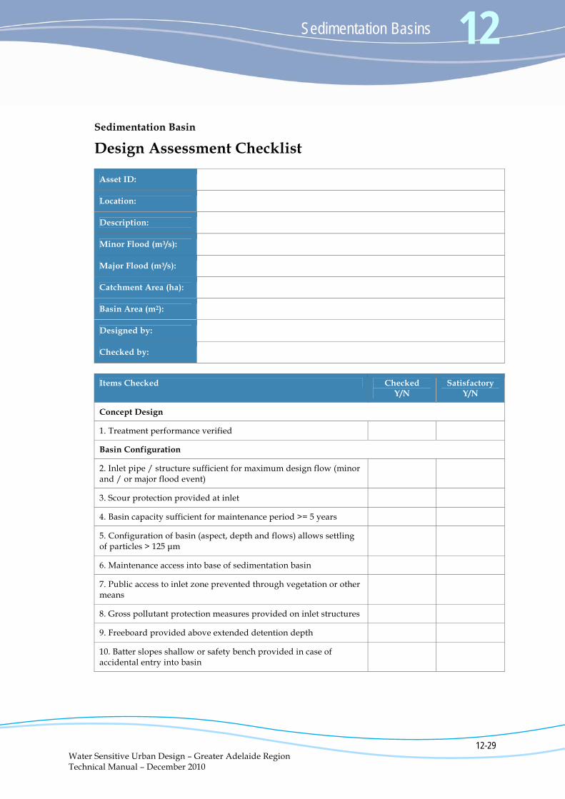
Checklist The Design Assessment Checklist (in Appendix A) presents the key design features that should be reviewed when assessing the design of a sedimentation basin. These considerations include (but are not limited to):
Configuration;
Safety;
Maintenance; and
Operational issues.
Sedimentation Basins 12
12-15 Water Sensitive Urban Design – Greater Adelaide Region Technical Manual – December 2010
12.4 Design Tools A range of design tools is available to assist in the development of the concept and detailed design of sedimentation basins as detailed in Chapter 15 of the Technical Manual.
The modelling tools which are able available include:
MUSIC;
EPA SWMM;
XP SWMM;
Drains;
HecRas; and
E2
In addition, a range of hydrologic methods can be applied to estimate design flows for sedimentation basins. With typical catchment areas being relatively small, the rational method design procedure is considered to be the most suitable method. For sedimentation basins with large catchments (greater than 50 hectares), a runoff routing model should be used to estimate design flows.
12 Sedimentation Basins
12-16 Water Sensitive Urban Design – Greater Adelaide Region Technical Manual – December 2010
12.5 Construction Process The risks to successful construction and establishment of a sedimentation basin during the construction process generally relate to the following:
Construction activities which can generate large sediment loads in runoff; and
Construction traffic and other works can result in damage to the sedimentation basins.
To overcome the challenges associated with delivering sedimentation basins, the basin should form part of the sediment and erosion control strategy.
Other aspects of the construction process are discussed below.
Construction Tolerances It is important to emphasise the significance of tolerances in the construction of sedimentation basins. Ensuring the relative levels of the control structures are correct is particularly important to achieve appropriate hydraulic functions. Generally, control structure tolerance of plus or minus 5 mm is considered acceptable. Additionally, the bathymetry of the sedimentation basin must ensure appropriate storage is available for accumulated sediment. In this regard, an earthworks tolerance of plus or minus 25 mm is considered acceptable (Gold Coast City Council 2007).
Sourcing Sedimentation Basin Vegetation In the majority of cases, the sedimentation basin will form an inlet pond to a constructed wetland or bioretention basin. If so, the landscape and vegetation design of the sedimentation basin will be undertaken in conjunction with the vegetation design of the other treatment measures and hence ordering of plant stock can be combined into one order.
Availability of vegetation is dependent upon many factors including demand, season and seed availability. To ensure the planting specification can be accommodated, the minimum recommended lead time for ordering plants is three to six months. This generally allows adequate time for plants to be grown to the required size.
Topsoil Specification and Preparation During the sedimentation basin construction process, topsoil is to be stripped and stockpiled for possible reuse as a plant growth medium. It is important to test the quality of the local topsoil to determine the soil’s suitability for reuse as a plant growth medium.
Sedimentation Basins 12
12-17 Water Sensitive Urban Design – Greater Adelaide Region Technical Manual – December 2010
Remediation may be necessary to improve the soil’s capacity to support plant growth and to suit the intended plant species. Soils applied to the littoral zones of sedimentation basins must also be free from significant weed seed banks as labour intensive weeding can incur large costs in the initial plant establishment phase.
On some sites, topsoils may be non-existent and material will need to be imported.
Checklist The Construction Process Checklist (see Appendix A) presents the key items to be reviewed when inspecting the sedimentation basin during and at the completion of construction.
12 Sedimentation Basins
12-18 Water Sensitive Urban Design – Greater Adelaide Region Technical Manual – December 2010
12.6 Maintenance Requirements Typical maintenance of sedimentation basins will involve:
Routine inspection of the sedimentation basin to identify depth of sediment accumulation, damage to vegetation, scouring, or litter and debris build up (after the first three significant storm events and then at least every three months);
Routine inspection of inlet and outlet points to identify any areas of scour, litter build up and blockages;
Removal of litter and debris;
Removal and management of invasive weeds (both terrestrial and aquatic);
Periodic (usually every five years) draining and desilting, which will require excavation and dewatering of removed sediment (and disposal to an approved location);
Regular watering of littoral vegetation during plant establishment;
Replacement of plants that have died (from any cause) with plants of equivalent size and species as detailed in the planting schedule; and
Inspections are also recommended following large storm events to check for scour and damage.
Sedimentation basins are designed with a sediment storage capacity to ensure sediment removal is only required approximately every five years. However, as listed above, regular checks of sediment build up will be required as sediment loads from developing catchments vary significantly. The basin must be cleaned out when it becomes more than half full of accumulated sediment.
Provision to drain the sedimentation basin of water for maintenance must be considered in the design, or alternatively, a pump can be used to draw down the basin. Appropriate approvals should be obtained to discharge flows, depending on where the water is to be discharged.
Similar to other types of WSUD measures, debris removal is an ongoing maintenance requirement. Debris, if not removed, can block inlets or outlets, and can be unsightly if deposited in a visible location. Inspection and removal of debris should be done regularly and debris removed whenever it is observed on the site.
Analysis of the characteristics of particulate nutrients and metals indicates that coarse to medium sized sediments (i.e. > 125 μm) have low concentrations of attached pollutants (e.g. nutrients and heavy metals) when compared to finer sediment and colloidal particles. Basins sized to target coarse to medium sized sediment are therefore expected to capture sediment that has low levels of contamination and is unlikely to require special handling and disposal. However, this should be verified prior to the disposal of the material.
Sedimentation Basins 12
12-19 Water Sensitive Urban Design – Greater Adelaide Region Technical Manual – December 2010
All maintenance activities should be specified in a maintenance plan (and associated maintenance inspection forms) to be developed as part of the design process. Maintenance personnel and asset managers will use this plan to ensure the sedimentation basin continues to function as designed. The maintenance plan should include a clearly labelled schematic layout of the site identifying all structures, plantings, open space, water bodies and paths.
The maintenance plan and forms should address the following:
Inspection frequency;
Maintenance frequency;
Data collection/storage requirements (i.e. during inspections);
Detailed clean out procedures (main element of the plan) including:
- Equipment needs
- Maintenance techniques
- Occupational health and safety
- Public safety
- Environmental management considerations
- Disposal requirements (of material removed)
- Access issues
Stakeholder notification requirements;
Data collection requirements (if any); and
Design details.
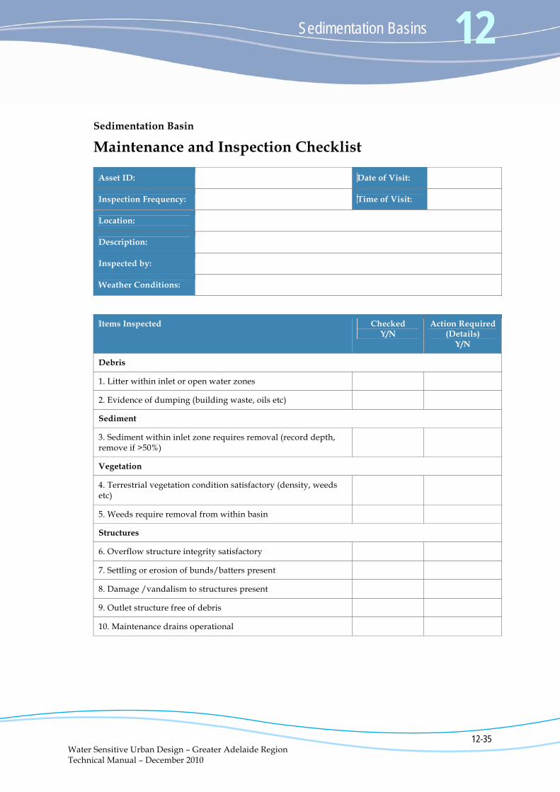
An example Operation and Maintenance Inspection Checklist is included in Appendix A. This checklist should be developed on a site-specific basis as the configuration and nature of sedimentation basins varies significantly.
The maintenance checklist developed should be used whenever an inspection is conducted, and kept as a record on the asset condition and the quantity of removed pollutants over time. Inspections should occur every one to six months, depending on the size and complexity of the system.
More detailed site specific maintenance schedules should be developed for major sedimentation basins and include a brief overview of the operation of the system and key aspects to be checked during each inspection.
12 Sedimentation Basins
12-20 Water Sensitive Urban Design – Greater Adelaide Region Technical Manual – December 2010
12.7 Useful Resources and Further Information
Fact Sheets www.brisbane.qld.gov.au/bccwr/lib184/sedimentation_basin_72dpi_rgb_nobleed.pdf
Sedimentation Basin fact sheet, Brisbane City Council
www.brisbane.qld.gov.au/bccwr/lib184/wsud%20practice%20note%2004%20sedimentation%20basins.pdf
Practice Note 4 Sedimentation Basins, Brisbane City Council
Legislation Information www.legislation.sa.gov.au/LZ/C/POL/ENVIRONMENT%20PROTECTION%20(WATER%20QUALITY)%20POLICY%202003/CURRENT/2003.-.UN.PDF
Environment Protection (Water Quality) Policy 2003
www.legislation.sa.gov.au/LZ/C/POL/ENVIRONMENT%20PROTECTION%20(NOISE)%20POLICY%202007/CURRENT/2007.-.UN.PDF
Environment Protection (Industrial Noise) Policy 1994
www.epa.sa.gov.au/pdfs/info_construction.pdf
EPA information sheet on Construction Noise
www.epa.sa.gov.au/pdfs/info_noise.pdf
EPA information sheet on Environmental Noise
www.epa.sa.gov.au/pdfs/building_sites.pdf
EPA Handbook for Pollution Avoidance on Building Sites
www.epa.sa.gov.au/pdfs/bccop1.pdf
Stormwater Pollution Prevention Code of Practice for the Building and Construction Industry
Design Information www.melbournewater.com.au/content/library/wsud/melbourne_water_wetland_design_guide.pdf
Constructed Wetland Systems – Design Guide for Developers
http://waterbydesign.com.au/TechGuide/
Technical Design Guidelines for South East Queensland – Chapter 4 Sediment Basins
Sedimentation Basins 12
12-21 Water Sensitive Urban Design – Greater Adelaide Region Technical Manual – December 2010
www.goldcoast.qld.gov.au/gcplanningscheme_policies/attachments/policies/policy11/section_13_5_sedimentation_basins.pdf
Water Sensitive Urban Design Guidelines – Gold Coast City Council – Section 13.5 Sedimentation Basins
(Websites current at August 2010)
12 Sedimentation Basins
12-22 Water Sensitive Urban Design – Greater Adelaide Region Technical Manual – December 2010
12.8 References BMT WBM (2008). National Guidelines for Evaluating Water Sensitive Urban Design (WSUD). March. www.nwc.gov.au/publications/index.cfm. Gold Coast City Council (2007). Water Sensitive Urban Design Guidelines. June. www.goldcoast.qld.gov.au/gcplanningscheme_policies/policy_11.html#guidelines. IEAust (2006). Australian Runoff Quality: A Guide to Water Sensitive Urban Design. New South Wales. Melbourne Water (2005a). Constructed Wetland Systems - Design Guidelines for Developers. Melbourne, Victoria. www.melbournewater.com.au/content/library/wsud/melbourne_water_wetland_design_guide.pdf. Melbourne Water (2005b). WSUD Engineering Procedures: Stormwater. CSIRO Publishing. Moreton Bay Waterways and Catchments Partnership (2006). Water Sensitive Urban Design Technical Design Guidelines for South East Queensland. http://waterbydesign.com.au/TechGuide/. Upper Parramatta River Catchment Trust (2004). Water Sensitive Urban Design, Technical Guidelines for Western Sydney. Prepared by URS Australia Pty Ltd. www.wsud.org/tools-resources/.
(Websites current at August 2010)
Sedimentation Basins 12
12-23 Water Sensitive Urban Design – Greater Adelaide Region Technical Manual – December 2010
Appendix A
Checklists
The Site Inspection Checklist was developed specifically for these guidelines. The remaining checklists have been modified for South Australian designs and conditions from checklists and forms provided in Upper Parramatta River Catchment Trust (2004), Melbourne Water (2005b), IEAust (2006), Gold Coast City Council (2007) and BMT WBM (2008).
All parts of all checklists should be completed. Even if design checks or field inspections were not performed, it is important to record the reasons for this in the relevant checklists.

Sedimentation Basins 12
12-25 Water Sensitive Urban Design – Greater Adelaide Region Technical Manual – December 2010
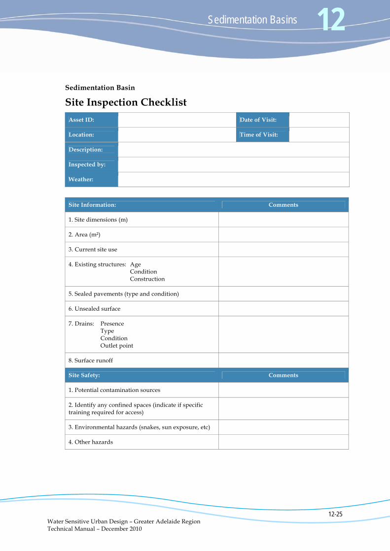
Sedimentation Basin
Site Inspection Checklist
Asset ID: Date of Visit:
Location: Time of Visit:
Description:
Inspected by:
Weather:
Site Information: Comments
1. Site dimensions (m)
2. Area (m²)
3. Current site use
4. Existing structures: Age Condition Construction
5. Sealed pavements (type and condition)
6. Unsealed surface
7. Drains: Presence Type Condition Outlet point
8. Surface runoff
Site Safety: Comments
1. Potential contamination sources
2. Identify any confined spaces (indicate if specific training required for access)
3. Environmental hazards (snakes, sun exposure, etc)
4. Other hazards
12 Sedimentation Basins
12-26 Water Sensitive Urban Design – Greater Adelaide Region Technical Manual – December 2010
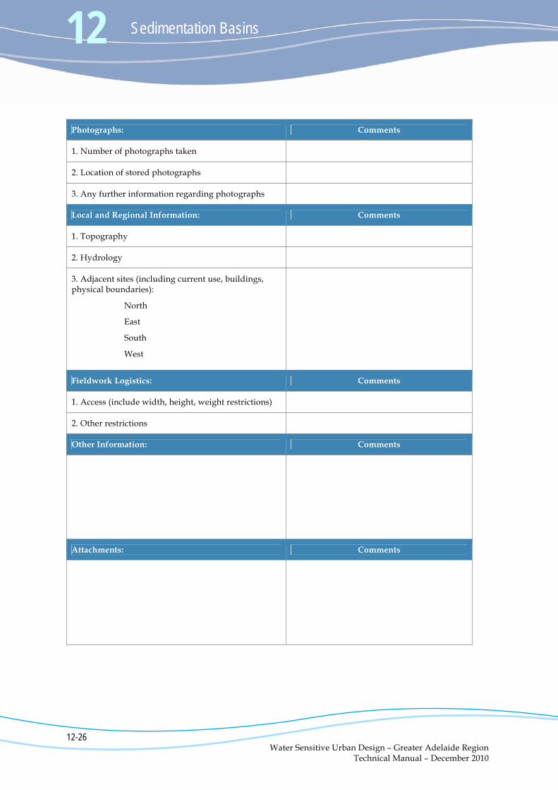
Photographs: Comments
1. Number of photographs taken
2. Location of stored photographs
3. Any further information regarding photographs
Local and Regional Information: Comments
1. Topography
2. Hydrology
3. Adjacent sites (including current use, buildings, physical boundaries):
North
East
South
West
Fieldwork Logistics: Comments
1. Access (include width, height, weight restrictions)
2. Other restrictions
Other Information: Comments
Attachments: Comments
Sedimentation Basins 12
12-27 Water Sensitive Urban Design – Greater Adelaide Region Technical Manual – December 2010
Sketch of Site (on this page please provide a rough sketch of the site plan)

Sedimentation Basins 12
12-29 Water Sensitive Urban Design – Greater Adelaide Region Technical Manual – December 2010
Sedimentation Basin
Design Assessment Checklist
Asset ID:
Location:
Description:
Minor Flood (m3/s):
Major Flood (m3/s):
Catchment Area (ha):
Basin Area (m2):
Designed by:
Checked by:
Items Checked Checked Y/N
Satisfactory Y/N
Concept Design
1. Treatment performance verified
Basin Configuration
2. Inlet pipe / structure sufficient for maximum design flow (minor and / or major flood event)
3. Scour protection provided at inlet
4. Basin capacity sufficient for maintenance period >= 5 years
5. Configuration of basin (aspect, depth and flows) allows settling of particles > 125 μm
6. Maintenance access into base of sedimentation basin
7. Public access to inlet zone prevented through vegetation or other means
8. Gross pollutant protection measures provided on inlet structures
9. Freeboard provided above extended detention depth
10. Batter slopes shallow or safety bench provided in case of accidental entry into basin
12 Sedimentation Basins
12-30 Water Sensitive Urban Design – Greater Adelaide Region Technical Manual – December 2010
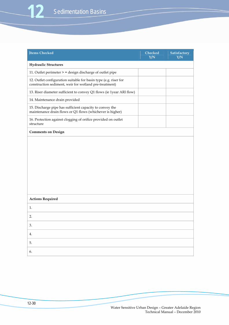
Items Checked Checked Y/N
Satisfactory Y/N
Hydraulic Structures
11. Outlet perimeter > = design discharge of outlet pipe
12. Outlet configuration suitable for basin type (e.g. riser for construction sediment, weir for wetland pre-treatment)
13. Riser diameter sufficient to convey Q1 flows (ie 1year ARI flow)
14. Maintenance drain provided
15. Discharge pipe has sufficient capacity to convey the maintenance drain flows or Q1 flows (whichever is higher)
16. Protection against clogging of orifice provided on outlet structure
Comments on Design
Actions Required
1.
2.
3.
4.
5.
6.
Sedimentation Basins 12
12-31 Water Sensitive Urban Design – Greater Adelaide Region Technical Manual – December 2010
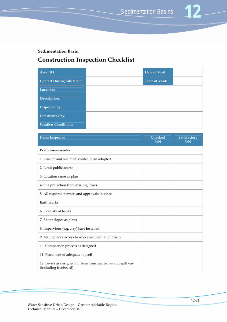
Sedimentation Basin
Construction Inspection Checklist
Asset ID: Date of Visit:
Contact During Site Visit: Time of Visit:
Location:
Description:
Inspected by:
Constructed by:
Weather Conditions:
Items Inspected Checked Y/N
Satisfactory Y/N
Preliminary works
1. Erosion and sediment control plan adopted
2. Limit public access
3. Location same as plan
4. Site protection from existing flows
5. All required permits and approvals in place
Earthworks
6. Integrity of banks
7. Batter slopes as plans
8. Impervious (e.g. clay) base installed
9. Maintenance access to whole sedimentation basin
10. Compaction process as designed
11. Placement of adequate topsoil
12. Levels as designed for base, benches, banks and spillway (including freeboard)
12 Sedimentation Basins
12-32 Water Sensitive Urban Design – Greater Adelaide Region Technical Manual – December 2010
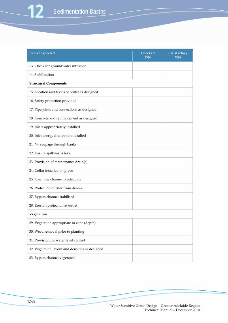
Items Inspected Checked Y/N
Satisfactory Y/N
13. Check for groundwater intrusion
14. Stabilisation
Structural Components
15. Location and levels of outlet as designed
16. Safety protection provided
17. Pipe joints and connections as designed
18. Concrete and reinforcement as designed
19. Inlets appropriately installed
20. Inlet energy dissipation installed
21. No seepage through banks
22. Ensure spillway is level
23. Provision of maintenance drain(s)
24. Collar installed on pipes
25. Low flow channel is adequate
26. Protection of riser from debris
27. Bypass channel stabilised
28. Erosion protection at outlet
Vegetation
29. Vegetation appropriate to zone (depth)
30. Weed removal prior to planting
31. Provision for water level control
32. Vegetation layout and densities as designed
33. Bypass channel vegetated
Sedimentation Basins 12
12-33 Water Sensitive Urban Design – Greater Adelaide Region Technical Manual – December 2010
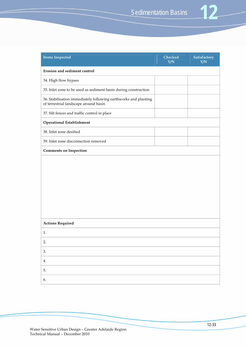
Items Inspected Checked Y/N
Satisfactory Y/N
Erosion and sediment control
34. High flow bypass
35. Inlet zone to be used as sediment basin during construction
36. Stabilisation immediately following earthworks and planting of terrestrial landscape around basin
37. Silt fences and traffic control in place
Operational Establishment
38. Inlet zone desilted
39. Inlet zone disconnection removed
Comments on Inspection
Actions Required
1.
2.
3.
4.
5.
6.

Sedimentation Basins 12
12-35 Water Sensitive Urban Design – Greater Adelaide Region Technical Manual – December 2010
Sedimentation Basin
Maintenance and Inspection Checklist
Asset ID: Date of Visit:
Inspection Frequency: Time of Visit:
Location:
Description:
Inspected by:
Weather Conditions:
Items Inspected Checked Y/N
Action Required (Details)
Y/N
Debris
1. Litter within inlet or open water zones
2. Evidence of dumping (building waste, oils etc)
Sediment
3. Sediment within inlet zone requires removal (record depth, remove if >50%)
Vegetation
4. Terrestrial vegetation condition satisfactory (density, weeds etc)
5. Weeds require removal from within basin
Structures
6. Overflow structure integrity satisfactory
7. Settling or erosion of bunds/batters present
8. Damage /vandalism to structures present
9. Outlet structure free of debris
10. Maintenance drains operational
12 Sedimentation Basins
12-36 Water Sensitive Urban Design – Greater Adelaide Region Technical Manual – December 2010
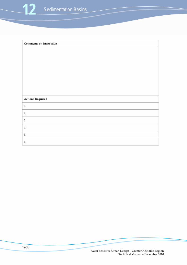
Comments on Inspection
Actions Required
1.
2.
3.
4.
5.
6.