Embed Size (px)
Citation preview

Chapter 15 – Series & Parallel ac Circuits
Lecture 21
by Moeen Ghiyas
19/04/23 1

Chapter 15 – Series & Parallel ac Circuits

(Parallel ac Circuits)
Admittance and Susceptance
Parallel ac Networks
Current Divider Rule
Frequency Response Of The Parallel R-L Network
Summary of Parallel ac Circuits
19/04/23 3
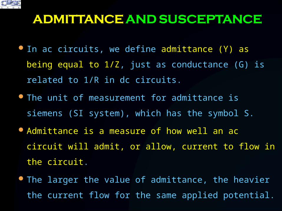
In ac circuits, we define admittance (Y) as being equal to 1/Z, just
as conductance (G) is related to 1/R in dc circuits.
The unit of measurement for admittance is siemens (SI system),
which has the symbol S.
Admittance is a measure of how well an ac circuit will admit, or
allow, current to flow in the circuit.
The larger the value of admittance, the heavier the current flow for
the same applied potential.

The total admittance of a circuit can also be found by finding the
sum of the parallel admittances.
The total impedance ZT of the circuit is then 1/YT

We know that conductance is the reciprocal of resistance, and
The reciprocal of reactance (1/X) is called susceptance and is a
measure of how susceptible an element is to the passage of
current through it.
Susceptance is also measured in siemens and is represented by
the capital letter B.
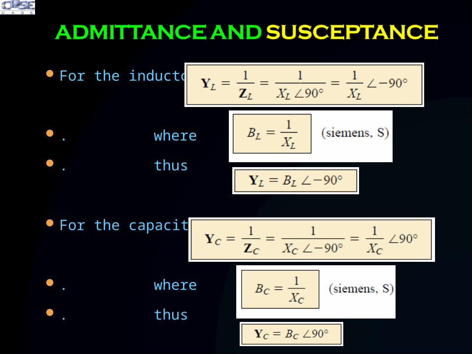
For the inductor,
. where
. thus
For the capacitor,
. where
. thus

For parallel ac circuits, the admittance diagram is used with the
three admittances, represented as shown in fig
Note that the conductance (like resistance) is on the positive real
axis, whereas inductive and capacitive susceptances are in direct
opposition on the imaginary axis.

For any configuration (series, parallel, series-parallel,
etc.), the angle associated with the total admittance is the
angle by which the source current I leads the applied
voltage E.
For inductive networks, θT is negative, whereas for
capacitive networks, θT is positive.

EXAMPLE - For the network of fig:
a) Find the admittance of each parallel branch.
b) Determine the input admittance.
c) Calculate the input impedance.
d) Draw the admittance diagram.
Solution:

EXAMPLE - For the network of fig:
a) Find the admittance of each parallel branch.
Solution:

EXAMPLE - For the network of fig:
b) Determine the input admittance.
c) Calculate the input impedance.
Solution:
b) .
c) .

EXAMPLE - For the network of fig:
d) Draw the admittance diagram.
Solution:

Step 1 – Determine the total
impedance or admittance
Step 2 – Using Ohm’s Law
Calculate source current
Calculate branch currents
Step 3 – Apply KCL,
Step 4 – Calculate Power,

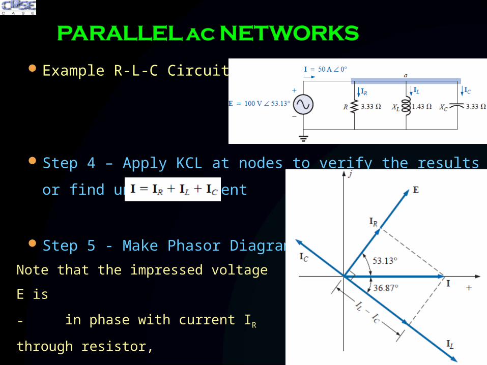
Example R-L-C Circuit
Step 0 - Converting to phasor notation

Example R-L-C Circuit
Step 1 – YT and ZT

Example R-L-C Circuit
Step 2 – Admittance
Diagram
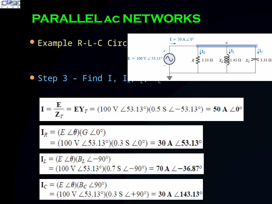
Example R-L-C Circuit
Step 3 – Find I, IR,IL, IC
Example R-L-C Circuit
Step 4 – Apply KCL at nodes to verify the results or find unknown
current
Step 5 - Make Phasor Diagram
Note that the impressed voltage E is
- in phase with current IR through
resistor,
- leads current IL through inductor
by 90°,
- and lags current IC of capacitor by
90°.

Example R-L-C Circuit
Step 6 – Convert V and I to time domain

Example R-L-C Circuit
Step 7 – Sketch waveform

Example R-L-C Circuit
Step 8 – Calculate power
or
or
Step 9 – Power factor
or

The basic format for the current divider rule in ac circuits
is exactly the same as that for dc circuits

EXAMPLE - Using the current divider rule, find the current through
each parallel branch of Fig
Solution:

EXAMPLE - Using the current divider rule, find the current through
each parallel branch of Fig

Let us now note the impact of frequency on the total impedance and
inductive current for the parallel R-L network
The fact that the elements are now in parallel, the element with the
smallest impedance will have the greatest impact on total impedance ZT
at that frequency

XL is very small at low frequencies compared to R, establishing XL as the
predominant factor in the specified frequency range
In other words, at low frequencies the network will be primarily inductive,
and the angle associated with the total impedance will be close to 90°,
as with a pure inductor.

As the frequency increases, XL will increase and at particular
frequency it equals the impedance of the resistor in circuit which
can be determined in the manner: XL = R, thus 2πf2L = R

Plots of θT versus frequency also reveals the transition from an
inductive network to resistive characteristics.

A series R-C and a parallel R-L network will have an
impedance level that approaches the resistance of the
network at high frequencies.
The (R-C series) capacitive circuit approaches the level from
above, whereas the (R-L parallel) inductive network does the
same from below.
Conversely, for the series R-L circuit and the parallel R-C
network, the total impedance will begin at the resistance
level and then display the characteristics of the reactive
elements at high frequencies.

The total admittance (impedance) will be frequency dependent.
The impedance of any one element can be less than the total
impedance (recall that for dc circuits the total resistance must
always be less than the smallest parallel resistor).
Depending on the frequency applied, the same network can be
either predominantly inductive or predominantly capacitive.
At lower frequencies the inductive elements will usually have the
most impact on the total impedance, while at high frequencies the
capacitive elements will usually have the most impact.
The magnitude of the current through any one branch can be
greater than the source current.

The magnitude of the current through an element is directly related
to the magnitude of its impedance
The current through a coil is always in direct opposition with the
current through a capacitor on a phasor diagram.
The applied voltage is always in phase with the current through
the resistive elements, leads the current through all the inductive
elements by 90°, and lags the current through all capacitive
elements by 90°.
The smaller the resistive element of a network compared to the
net reactive susceptance, the closer the power factor is to unity.

Admittance and Susceptance (Parallel ac Circuits)
Parallel ac Networks
Current Divider Rule
Frequency Response Of The Parallel R-L Network
Summary of Parallel ac Circuits

19/04/23 34