Embed Size (px)
Citation preview
1
Before you begin: Turn on the sound on your computer. There is audio to accompany this presentation.
Chapter 16
Bulk Forming Processes
MET 33800 Manufacturing Processes
Materials Processing
Chapters 15-17
Chapters 30-33
Chapters 20-27
Chapters 11-13
Chapter 16 - 2
Types of Deformation (Chapter 16)
The deformation that is done can be classified in several different ways:
Bulk deformation – flow in three dimensions.
Shearing – compressive cutting type of operation.
Bending – deformation about an axis.
Combinations of the above.
Chapter 16 - 3

2
Introduction Shaping of materials by deformation is as old as
recorded history including Biblical references.
Many processes common during Middle Ages.
Saugus Iron Works near Boston operated forging, rolling and slitting mill in 1680.
Basic concepts have remained unchanged throughout history, however, details and equipment have evolved considerably.
Chapter 16 - 4
Classification of Processes A wide variety of deformation processes have been
developed.
Classification methods:
Temperature: Hot, Warm, Isothermal, Cold.
Process Stage: Primary, secondary.
Size and Shape Change: Bulk, Sheet-forming.
Chapter 16 - 5
Process Stage Primary processes reduce
cast material into intermediate shapes such as slabs, blooms, and billets.
Secondary processes further convert these shapes into semi-finished or finished products.
Some processes fit into both categories…….
Chapter 16 - 6

3
Process Stage
Figure 16-1. Flow chart for the production of various finished and semifinished steel shapes.
Chapter 16 - 7
Size and Shape Changing Bulk Deformation Processes – Surface area,
thicknesses, cross-sections and/or shape is significantly changed. However, volume remains constant.
■ Bulk deformation performed in all temperature regimes.
Chapter 16 - 8
Size and Shape Changing Sheet-Forming Operations – Deformation of a material
where the thickness and surface area remain relatively constant.
Most sheet-forming is performed cold due to cooling issues.
Chapter 16 - 9

4
Size and Shape Changing Still some areas of confusion…example coining
Begins with sheet metal, alters thickness in a complex manner so really a bulk process.
Chapter 16 - 10
Bulk Deformation Processes Rolling
Forging
Extrusion
Wire, Rod and Tube Drawing
Cold Forming, Cold Forging and Impact Extrusion
Piercing
Other Squeezing Processes
Chapter 16 - 11
Rolling Usually the first process that is used to convert a
material into a finished wrought product.
Changes shape of metal through compressive forces exerted by rolls.
Predominate process with ~90% of all metal products experiencing at least one rolling operation.
Chapter 16 - 12

5
Rolling Shapes Blooms: Square or rectangular cross-section.
Thickness > 6 inches.
Width ≤ 2x thickness.
Slabs: Rectangular solid.
Width > 2x thickness.
Billets: Square or circular cross-section.
Usually smaller than bloom.
Chapter 16 - 13
Basic Rolling Process Metal is passed between
two rolls that rotate in opposite directions.
The gap between the rolls is somewhat less than the original thickness of the starting material.
Contact friction pulls metal between rollers.
Figure 16-2. Schematic representation of the hot-rolling process.
Chapter 16 - 14
Basic Rolling Process Metal is squeezed and
elongated to compensate for the decrease in thickness or cross-sectional area.
The amount of deformation that can come from a single pass depends on friction.
Speed of material exiting rolls is higher than entry speed.
Rolling Illustration. Note that the core zone is not affected by the
rolling process.
Chapter 16 - 15

6
Hot Rolling Characteristics that make hot rolling an attractive
means of producing a desired shape:
Elevated temperatures weaken materials and make them more ductile.
Massive reductions can occur with recrystallization.
No fear of fracture due to lower ductility.
In steels, weaker structure transforms into stronger materials upon cooling.
Chapter 16 - 16
Rolling Temperatures Temperature control is a requirement for success.
Starting material must be heated to a uniform elevated temperature.
If a part begins to cool prior to working, the cooler surface will resist deformation and tend to crack.
In high volume processes, it is common to use continuous cast feed stock which eliminates the need for additional handling and heating.
Chapter 16 - 17
Rolling Temperatures Small volume operations must use gas or oil fired
soaking pits or furnaces.
Hot rolling is usually terminated when temperatures fall to 100–200 °F above recrystallization.
For plain carbon steels, soaking temperatures are about 2200 °F.
Chapter 16 - 18

7
Cold Rolling Dominant cold working process in terms of tonnages.
Sheets, strips, bars and rods are cold rolled.
Yields extremely smooth surfaces and accurate dimensions.
Strain hardening can add 20% strength to the material.
Chapter 16 - 19
Cold Rolled Conditions Skin-Rolled: material thickness reduced 0.5-1.0% to
produce smooth and uniform surface.
Other Conditions: material thickness reduced up to 50%. Yield points increase, properties become directional and ductility decreases:
Quarter-Hard: material can be folded back on itself.
Half-Hard: material can be bent 90° before fracture.
Full-Hard: material can be bent 45° before fracture.
Chapter 16 - 20
Flatness Control Uniform rolled product thickness requires uniform roll
gaps.
Problem is that rolls are supported only at the end by bearings.
Figure 16-7. (a) Loading on a rolling mill. (b) Elastic response to three-point bending.
Chapter 16 - 21
8
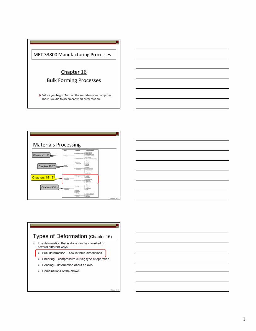
Flatness Control Solutions:
Use four-high or cluster configuration.
Use crowned or barrel shaped rolls – requires consistent material thickness and conditions.
Reduce forces by using smaller-diameter rolls, increased workpiece temperature, smaller reduction amounts, and/or increased tension on workpiece.
Figure 16-8. Use of a crowned roll to compensate for roll flexure.
Chapter 16 - 22
Rolling Mill Configurations Smaller diameters result in
less contact area.
Usually required for thin materials.
Smaller diameter rolls result:
Lower forces.
Less energy required.
Reduced roll stiffness prone to bending.
Figure 16-4. The effect of roll diameter on length of contact for a given reduction.
Chapter 16 - 23
Rolling Mill Configurations Rolling mills come in a
variety of configurations
Two-high
Two-high Reversing
Three-high
Four-high
Cluster
Figure 16-3. Various roll configurations used in rolling operations.
Chapter 16 - 24
9
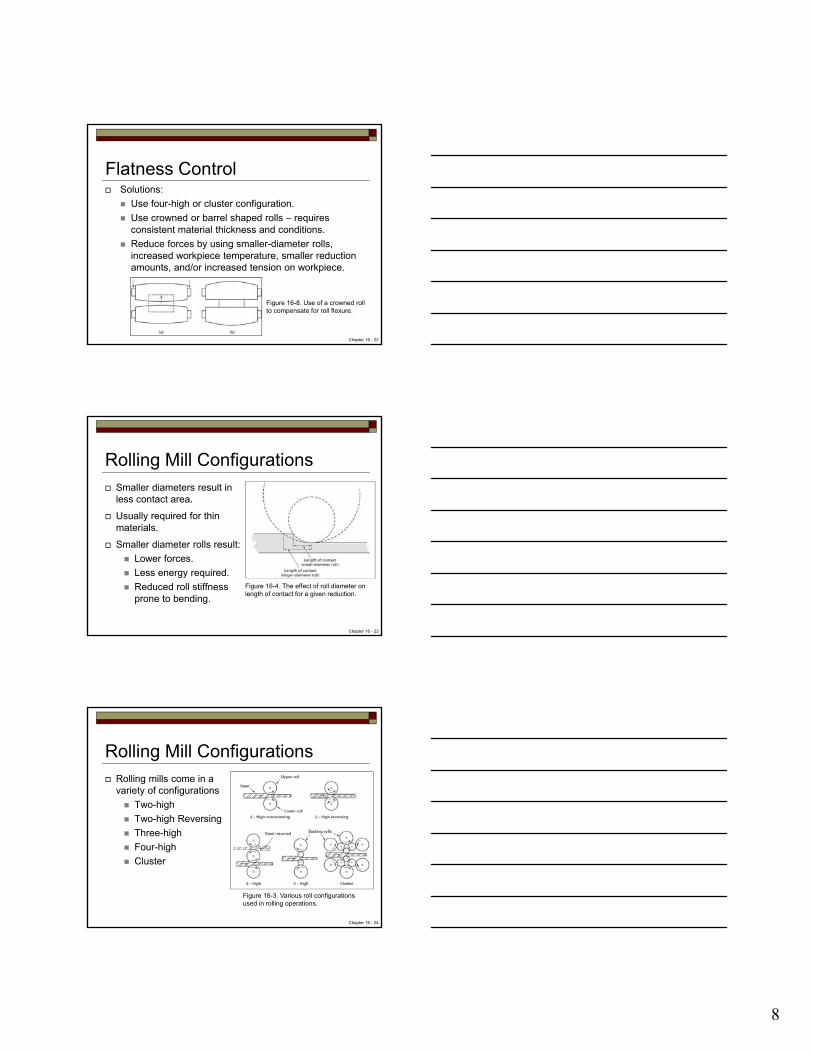
Two-High Two-high nonreversing is simplest design but material
can only pass through in one direction.
Two-high reversing permits back and forth rolling, but the materials must be stopped, reversed and brought back to rolling speeds between each pass.
Chapter 16 - 25
Three-High Three high mill eliminated the need for roll reversal but
requires some form of elevator on each side of the mill to raise or lower the material or shift the product between passes.
Chapter 16 - 26
Four-High and Cluster Smaller diameter rolls require lower force and less
energy – however, the smaller roll provides less stiffness and is prone to flexing.
Four high and cluster arrangements use backup rolls to help support the smaller work rolls.
Chapter 16 - 27

10
Four-High and Cluster Four-high and cluster configurations are used in rolling
wide plate, sheet and for foil.
Foil is almost always produced on a cluster mill since small thickness required small diameter rolls. Rolls can be as small as 6mm (1/4 in).
To counter the need for even smaller rollers, some foils are produced by pack rolling where 2 or more layers are rolled simultaneously.
Check aluminum foil – one side shiny, one side dull. Evidence of pack rolling – which side was against the roll?
Chapter 16 - 28
Shiny side
Roll-Pass Shapes such as structural shapes and railroad rails
use sets of rolls with grooves which progressively form the desired shape.
Material cross-section is reduced and physical properties such as strength are enhanced.
Figure 16-5. Typical roll-pass sequences used in producing structural shapes.
Chapter 16 - 29
Continuous Rolling Mills If volume is high enough – continuous rolling mills are
utilized.
May consist of a stands of 4 to 11 four-high rolling mills
Timing is key in continuous rolling:
The same amount of material must pass through each stand in the same amount of time.
Speeds start of slow – but easily reach up to 70mph at the end of the line!!!
Chapter 16 - 30

11
Continuous Rolling MillsContinuous rolling mill
illustrations.
Chapter 16 - 31
Ring Rolling Special rolling process
where one roll is placed through the hold of a thick walled ring and a second roll presses in from the outside.
Resulting product is a seamless ring with a circumferential grain orientation.
Figure 16-6. Schematic of a horizontal ring rolling operation. As the thickness is reduced, the diameter will increase.
Chapter 16 - 32
Ring Rolling Result is a seamless ring that have uses in:
Rockets
Turbines
Airplanes
Pipelines
Pressure vessels
Size as large as 25’ with face heights up to 80”
Chapter 16 - 33

12
Hot-Rolled Quality Hot rolled properties can depend on thickness.
Little to high grain structure directionality depending on the process.
Little or no residual stresses.
Non-metallic inclusions do not recrystallize and can result in directionality.
Non-uniform cooling can bring residual stresses and directionality.
Chapter 16 - 34
Hot-Rolled Quality Products are usually uniform and dependable in
quality.
Unusual to find voids, seams or laminations.
Surfaces are rough and covered with high temp oxide called mill scale.
Removed by pickling process.
Dimensional tolerance varies –generally within 2-5% of specified dimension.
Chapter 16 - 35
Cold-Rolled Quality Superior surface finish and dimensional precision.
Typically offer enhanced strength through strain hardening.
Chapter 16 - 36

13
Forging Family of processes where the deformation is induced
by localized compressive forces.
Equipment can be in form of:
Hammers
Presses
Special forging machines
Deformation can be done hot, cold, warm or isothermal, but forging implies that the deformation occurs hot, above the recrystallization temperature.
Chapter 16 - 37
Forging Oldest known metalworking process.
Has evolved from pre-historic times, through blacksmithing to modern industrial applications.
Classification of deformation:
Drawn out – increase length / decrease cross section.
Upset – decrease length / increase cross section.
Squeezed – produce multi-directional flow.
Work is primarily uniaxial or multiaxial compression.
Chapter 16 - 38
Common Forging Processes Open die drop hammer
Impression die drop hammer
Press forging
Upset forging
Automatic hot forging
Roll forging
Swaging
Net-shape or near-net-shape forging
Chapter 16 - 39

14
Open-Die Drop Hammer Same type of forging as done in blacksmithing.
Massive equipment is used to impart repeated blows.
Impact is delivered by mechanical hammer:
Gravity drop – free falling ram.
Energy augmentation – air, steam or hydraulic.
CNC – can vary impact speed/energy.
Chapter 16 - 40
Open-Die Drop Hammer Open die forging does not fully control the flow of the
metal.
Operator must obtain desired shape by orienting and positioning the workpiece.
Figure 16-9. Double-framed drop hammer.
Chapter 16 - 41
Open-Die Drop Hammer
Figure 16-10. (top) Illustration of the unrestrained flow of material in open-die forging. (middle) Open-die forging of a multidiameter shaft. (bottom) Forging of a seamless ring by the open-die method.
Chapter 16 - 42

15
Impactor Forging Also known as counterblow.
Uses two horizontal hammers rather than a hammer and anvil arrangement.
Excess energy becomes recoil rather than lost to foundation.
Figure 16-13. Schematic diagram of an impactor in striking and returning modes.
Chapter 16 - 43
Impression-Die Hammer Forging Open die is not practical
for large scale production.
Impression or closed die overcomes those difficulties.
Uses shaped dies to control the flow of the metal.
Excess material squeezed out is called flash.
Figure 16-11. Schematic of the impression die forging process, showing partial die filling and the beginning of flash formation in the center sketch and the final shape with flash in the right-hand sketch.
Chapter 16 - 44
Flashless forging is true closed die forging – the metal is deformed in a cavity that provides total confinement.
Accurate workpiece sizing is required.
Forgings have about 20% higher strength/weight ratios compared to cast or machined parts.
Impression-Die Hammer Forging
Chapter 16 - 45

16
Figure 16-12. Impression drop-forging dies and the product resulting from each impression. Note the grain flow resulting from the forging process.
Impression-Die Hammer Forging
Chapter 16 - 46
Illustrations of impression or closed die drop-forging dies.
Impression-Die Hammer Forging
Chapter 16 - 47
Impression-Die Design Made from high alloy or tool steel – commonly referred
to die steels.
Have to be able to handle impact, wear, high temperatures and temperature cycling.
Design is important – critical elements are listed on page 412 of the text.
Accuracies of 0.02 to 0.03 inch possible.
Chapter 16 - 48

17
Press Forging Good for large pieces or thick products.
Deformation measured in terms of forces or pressure rather than energy.
Employs slower, squeeze deformation and flow:
Completely penetrates the material and produces more uniform deformation and flow.
Longer contact times results in surface cooling with loss of ductility and potential for cracking.
Heated dies used to limit surface cooling.
Chapter 16 - 49
Press Forging Mechanical presses use cams, cranks, toggles:
Capacities range from 300 – 18,000 tons.
Hydraulic presses use fluid pressure, are slower, more costly, but more massive and more flexible:
Capacities up to 50,000 tons working in U.S.
Screw presses use large flywheels to store a predetermined amount of energy.
Chapter 16 - 50
Upset Forging Increases the diameter by compressing its length.
Most widely used of all forging processes.
Can be done both hot and cold.
Starting stock is usually wire or rod, but can be up to bar 10” in diameter.
Used to form heads on bolts and other fasteners.
Generally uses multi-cavity, split dies.
Chapter 16 - 51

18
Upset Forging
Illustration: Example of parts produced by upset forging.
Chapter 16 - 52
Upset ForgingFigure 16-16. Set of upset-forging dies and punches. The product resulting from each of the four positions is shown along the bottom.
Chapter 16 - 53
Automatic Hot Forging Highly automated upset equipment in which mill length
steel bars 24’ long are fed into one end at room temperature and hot forged products emerge from the other end at 180 parts per minute.
Up to 12 lb in weight and 7 inch diameter.
Can be linked with cold forging.
Single production line can entail $10 million investment – only economic for mass production.
Chapter 16 - 54
19
Automatic Hot Forging
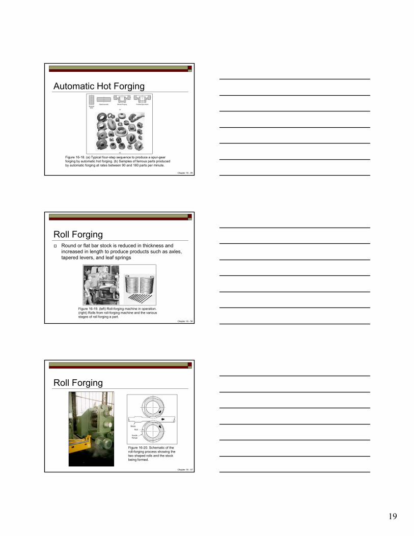
Figure 16-18. (a) Typical four-step sequence to produce a spur-gear forging by automatic hot forging. (b) Samples of ferrous parts produced by automatic forging at rates between 90 and 180 parts per minute.
Chapter 16 - 55
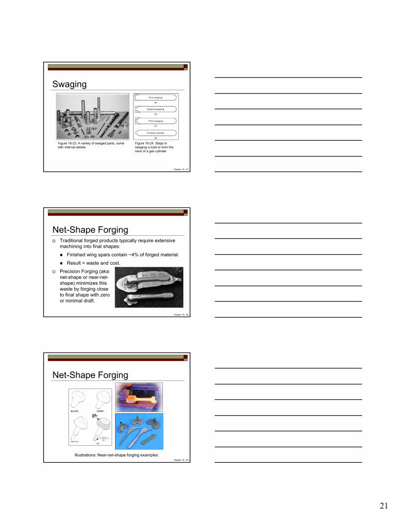
Roll Forging Round or flat bar stock is reduced in thickness and
increased in length to produce products such as axles, tapered levers, and leaf springs
Figure 16-19. (left) Roll-forging machine in operation. (right) Rolls from roll-forging machine and the various stages of roll forging a part.
Chapter 16 - 56
Roll Forging
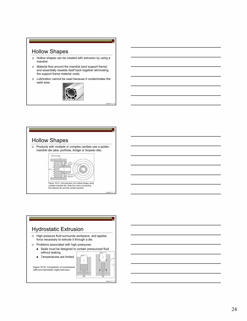
Figure 16-20. Schematic of the roll-forging process showing the two shaped rolls and the stock being formed.
Chapter 16 - 57

20
Swaging Also known as rotary swaging or radial forging
Involves hammering of a rod or tube to reduce its diameter and/or form a taper, or point.
The die itself acts as the hammer and repeated blows are delivered from various angles.
Also a process where material is forced into a confining die to reduce its diameter – which is performed hot.
Chapter 16 - 58
Swaging Process uses a set of tool steel dies with a hole in the
center.
External motor drives flywheel to generate centrifugal forces to open dies.
As spindle rotates, backing blocks are driven into opposing rollers.
Blocks must squeeze the dies back together until it clears the rollers.
Can generate as many as 3000 blows per minute.
Chapter 16 - 59
Swaging
Figure 16-22. Basic components and motions of a rotary swaging machine.
Figure 16-21. Tube being reduced in a rotary swaging machine.
Chapter 16 - 60
21
Swaging
Figure 16-24. Steps in swaging a tube to form the neck of a gas cylinder.
Figure 16-23. A variety of swaged parts, some with internal details.
Chapter 16 - 61
Net-Shape Forging Traditional forged products typically require extensive
machining into final shapes:
Finished wing spars contain ~4% of forged material.
Result = waste and cost.
Precision Forging (aka: net-shape or near-net-shape) minimizes this waste by forging close to final shape with zero or minimal draft.
Chapter 16 - 62
Net-Shape Forging
Illustrations: Near-net-shape forging examples.Chapter 16 - 63

22
Extrusion Metal is compressed and forced to flow through a
suitably shaped die to form a product with reduced by constant cross section.
May be performed hot or cold.
Hot typically used to reduce forces and eliminate cold-working effects.
Easier on materials with low yield strengths and hot working temperatures.
Material flows plastically through the die.
Chapter 16 - 64
Extrusion Extrusion analogy – toothpaste squeezed from a tube.
Figure 16-25. Direct extrusion schematic showing the various equipment components.
Chapter 16 - 65
Extrusion Metal flow during extrusion is complex.
Material near the center of the chamber can pass through die with little distortion.
Figure 16-29. Grid pattern showing metal flow in a direct extrusion.
Chapter 16 - 66

23
Extrusion Materials include aluminum, magnesium, copper, lead
and alloys of these metals are most commonly extruded.
Steels, stainless steels, nickel-based alloys and titanium can be extruded with special lubricants.
Figure 16-26. Typical shapes produced by extrusion. (left) Aluminum products. (right) Steel products.
Chapter 16 - 67
Advantages Can produce complex shapes that cannot be
manufactured by other methods such as rolling.
Conversion between products requires single die change.
Good surface finish and dimensional precision within 0.003 in.
Long product lengths up to 40 ft.
Little waste or scrap.
Chapter 16 - 68
Extrusion Methods Direct – Solid ram drives entire billet through stationary
die.
Indirect – A hollow ram pushed the die back through a stationary confined billet:
Force is less
Die life is longer
Figure 16-27. Direct and indirect extrusion.
Figure 16-28. Ram force related to position for Direct and indirect extrusion.
Chapter 16 - 69
24
Hollow Shapes Hollow shapes can be created with extrusion by using a
mandrel.
Material flow around the mandrel (and support frame) and essentially rewelds itself back together eliminating the support frame material voids.
Lubrication cannot be used because it contaminates the weld area
Chapter 16 - 70
Hollow Shapes Products with multiple or complex cavities use a spider-
mandrel die (aka: porthole, bridge or torpedo die).
Figure 16-31. Hot extrusion of a hollow shape using a spider-mandrel die. Note four arms connecting the external die and the central mandrel.
Chapter 16 - 71
Hydrostatic Extrusion High pressure fluid surrounds workpiece and applies
force necessary to extrude it through a die.
Problems associated with high pressures:
Seals must be designed to contain pressurized fluid without leaking.
Temperatures are limited.
Figure 16-32. Comparison of conventional (left) and hydrostatic (right) extrusion.
Chapter 16 - 72

25
Continuous Extrusion Conventional extrusion is discontinuous process.
If pushing force could be applied to the periphery of the feedstock – feedstock could be converted into continuous product.
Continuous copper extrusion. Continuous extrusion equipment.
Chapter 16 - 73
Wire, Rod and Tube Drawing Reduces the cross-section of material by pulling through
a die.
Similar to extrusion however stresses are now tensile (pulling) rather than compression (pushing).
Drawing is a cold-forming process:
One end of the material is pointed to fit through die.
Protruding material is gripped and pulled through die.
Material reduces in cross-section, elongates and strain hardens.
Chapter 16 - 74
Wire, Rod and Tube Drawing Reduction limited to 20-50% since higher reduction
requires higher pulling forces which may exceed the tensile strength of the material.
Multiple draws can be used to achieve final sizing. May require intermediate annealing to restore ductility of material.
Figure 16-34. Schematic diagram of the rod or bar drawing process.
Chapter 16 - 75

26
Wire, Rod and Tube Drawing Rod and bar drawing produces a product of a finite
length.
Tube drawing utilize mandrels to create the hollow interior.
Diameter range 0.5 to 10 inches.
Wire drawing is essentially the same as bar drawing except involves smaller diameter material.
Final product typically coiled due to long length.
Chapter 16 - 76
Rod and Bar Drawing
Figure 16-35. Diagram of a chain-driven multiple-die-draw bench used to produce finite lengths of straight rod or tube.
Chapter 16 - 77
Rod and Bar Drawing
100 Ton ferrous metal drawing machines
Chapter 16 - 78

27
Tube Drawing
Figure 16-36. Cold-drawing smaller tubing from larger tubing. The die sets the outer dimension while the stationary mandrel sizes the inner diameter.
Figure 16-37. Tube drawing with a floating plug.
Chapter 16 - 79
Wire Drawing
Figure 16-38. Schematic of wire drawing with a rotating draw block. The rotating motor on the draw block provides a continuous pull on the incoming wire.
Figure 16-39. Cross section through a typical carbide wire-drawing die showing the characteristic regions of the contour.
Chapter 16 - 80
Cold Forming Very common process in which slugs of material are
squeezed into shaped die cavities to produce finish parts.
Chip-less manufacturing – competes with some machining operations (reduces waste).
Generally associated with making small parts from weaker nonferrous materials.
Finished parts have good precision in terms of shape and size.
Chapter 16 - 81

28
Cold Heading Variation of upset forging.
Uses wire to produce enlarged features such as:
Bolt heads
Nails
Rivets
Specialized fasteners
Production rates to 600 pieces per minute.
Figure 16-41. Typical steps in a shearing and cold-heading operation.
Chapter 16 - 82
Impact (Cold) Extrusion Impact extrusion is a cold-forming type of extrusion.
Metal slug is placed into a die cavity.
Punch strikes the slug and metal flow forward, backward or both directions.
Production speeds to 60 strokes per minute.
First used for shaping low strength materials Pb, Sn, Zn and Al. Recently advances made to work with mild steel.
Chapter 16 - 83
Impact (Cold) Extrusion Products include:
Toothpaste tubes
Food and beverage cans
Electronic component cases
Battery cases.
Figure 16-43. Backward and forward extrusion with open and closed dies.
Chapter 16 - 84
29
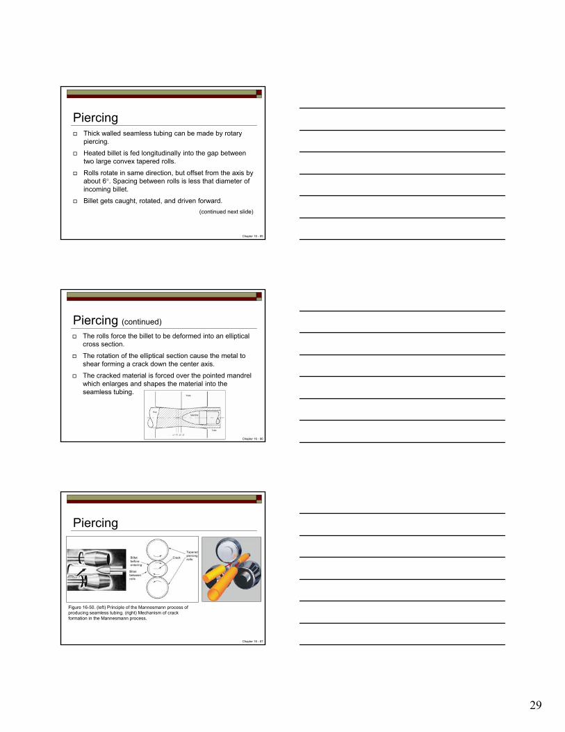
Piercing Thick walled seamless tubing can be made by rotary
piercing.
Heated billet is fed longitudinally into the gap between two large convex tapered rolls.
Rolls rotate in same direction, but offset from the axis by about 6°. Spacing between rolls is less that diameter of incoming billet.
Billet gets caught, rotated, and driven forward.
(continued next slide)
Chapter 16 - 85
Piercing (continued)
The rolls force the billet to be deformed into an elliptical cross section.
The rotation of the elliptical section cause the metal to shear forming a crack down the center axis.
The cracked material is forced over the pointed mandrel which enlarges and shapes the material into the seamless tubing.
Chapter 16 - 86
Piercing
Figure 16-50. (left) Principle of the Mannesmann process of producing seamless tubing. (right) Mechanism of crack formation in the Mannesmann process.
Chapter 16 - 87

30
Squeezing Squeezing processes include:
Roll Extrusion
Sizing
Riveting
Staking
Coining
Hubbing
Chapter 16 - 88
Roll Extrusion
Figure 16-51. The roll-extrusion process: (a) with internal rollers expanding the inner diameter; (b) with external rollers reducing the outer diameter.
Chapter 16 - 89
Roll extrusion Thin walled cylinders can be produced from thicker walled material
SizingSizing Involves squeezing all or selected regions of forgings, ductile castings, or powder metal products to achieve a prescribed thickness.
Chapter 16 - 90

31
Riveting An expanded head is formed on the shank end of a
fastener to permanently join sheets of plates of material.
Also classified as a joining processes.
Done “HOT” for structural applications.
Done “COLD” for manufactured products typically.
Chapter 16 - 91
Riveting
Figure 16-52. Joining components by riveting.
Figure 16-53. Rivets for use in “blind” riveting: (left) explosive type; (right) shank-type pull-up.
Chapter 16 - 92
Staking, Coining and Hubbing Staking - Method of permanently joining parts when a
segment of one part protrudes through a hold in another.
Coining – cold squeezing of metal while all surfaces are confined with a set of dies.
Hubbing – cold working process used to plastically deform recessed cavities.
Chapter 16 - 93

32
Staking, Coining and Hubbing
Figure 16-54. Permanently attaching a shaft to a plate by staking.
Figure 16-55. The coining process.
Chapter 16 - 94
Staking, Coining and Hubbing
Figure 16-56. Hubbing a die block in a hydraulic press.
Chapter 16 - 95
Surface Improvements Peening – mechanical work of surfaces by repeated
blows or impelled shot.
Puts surfaces into residual compression.
Improves the surface condition.
Improves fracture resistance.
Burnishing – rubbing a smooth, hard object over the surface irregularities that are produced by machining or shearing.
Chapter 16 - 96

33
Surface ImprovementsIllustrations: Shot Peening
Chapter 16 - 97
Surface Improvements
Figure 16-57. Tool for roller burnishing. The burnishing rollers move outward by means of a taper.
Chapter 16 - 98
The End – See Oncourse for Videos
Saugus Iron Works forging hammer (1680)
Chapter 16 - 99


![arXiv:1112.1037v1 [physics.ins-det] 5 Dec 2011Figure1. An SEM image of a gold stud bump before (left) and after (right) coining. Coining is performed by compressing the studs under](https://img.pdfslide.net/doc/110x75/5e7e8d69c5d0407f2447f2ad/arxiv11121037v1-5-dec-2011-figure1-an-sem-image-of-a-gold-stud-bump-before.jpg)