Embed Size (px)
Citation preview
ArchiCAD 11 manual
1/29 Abeyou wale Chapter 2 [email protected]
ArchiCAD 11 manual
Construction Elements
Chapter 2
ArchiCAD 11 manual
2/29 Abeyou wale Chapter 2 [email protected]
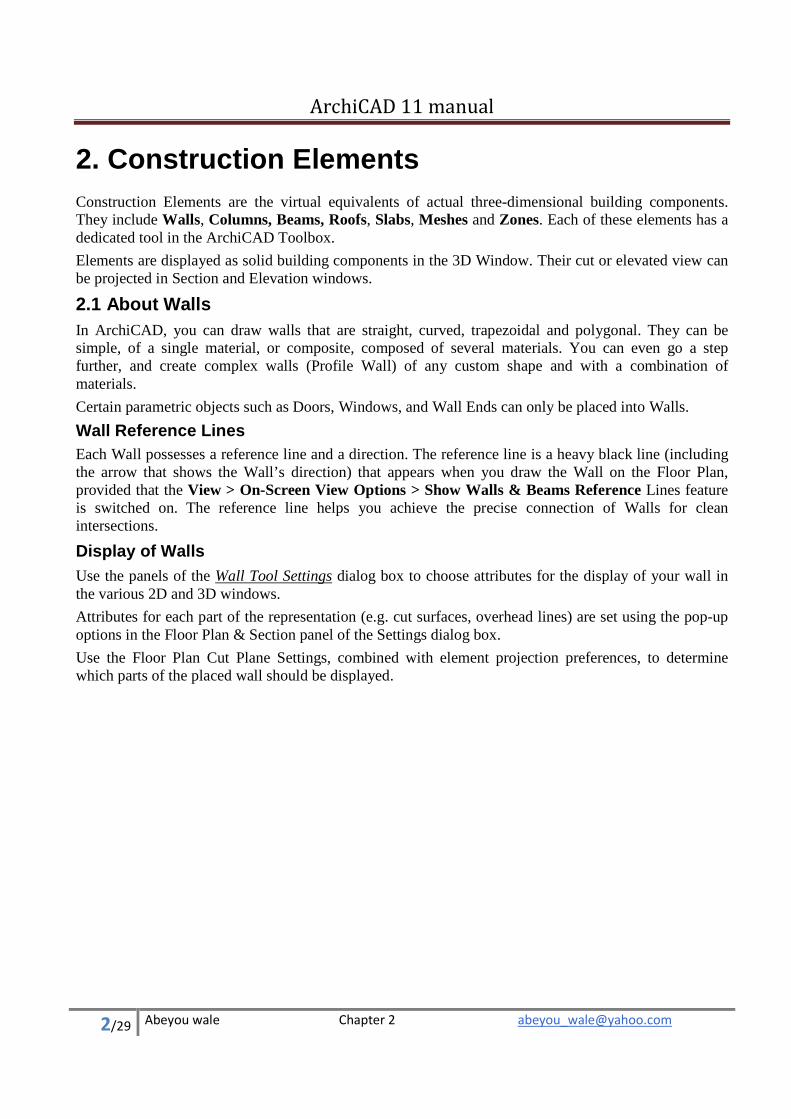
2. Construction Elements Construction Elements are the virtual equivalents of actual three-dimensional building components. They include Walls, Columns, Beams, Roofs, Slabs, Meshes and Zones. Each of these elements has a dedicated tool in the ArchiCAD Toolbox.
Elements are displayed as solid building components in the 3D Window. Their cut or elevated view can be projected in Section and Elevation windows.
2.1 About Walls In ArchiCAD, you can draw walls that are straight, curved, trapezoidal and polygonal. They can be simple, of a single material, or composite, composed of several materials. You can even go a step further, and create complex walls (Profile Wall) of any custom shape and with a combination of materials.
Certain parametric objects such as Doors, Windows, and Wall Ends can only be placed into Walls.
Wall Reference Lines
Each Wall possesses a reference line and a direction. The reference line is a heavy black line (including the arrow that shows the Wall’s direction) that appears when you draw the Wall on the Floor Plan, provided that the View > On-Screen View Options > Show Walls & Beams Reference Lines feature is switched on. The reference line helps you achieve the precise connection of Walls for clean intersections.
Display of Walls Use the panels of the Wall Tool Settings dialog box to choose attributes for the display of your wall in the various 2D and 3D windows.
Attributes for each part of the representation (e.g. cut surfaces, overhead lines) are set using the pop-up options in the Floor Plan & Section panel of the Settings dialog box.
Use the Floor Plan Cut Plane Settings, combined with element projection preferences, to determine which parts of the placed wall should be displayed.
ArchiCAD 11 manual
3/29 Abeyou wale Chapter 2 [email protected]
Create a Straight Wall The Single Straight Wall method produces one straight wall element at a time.
.
With the Wall Tool selected, choose the Straight Wall Geometry method from the Info Box and draw the wall segment on the plan.
In both Floor Plan and 3D, you define the length of Wall segments by clicking at their endpoints.
Create a Curved Wall With the Wall Tool selected, choose one of the three Curved Wall Geometry Methods from the Info Box.
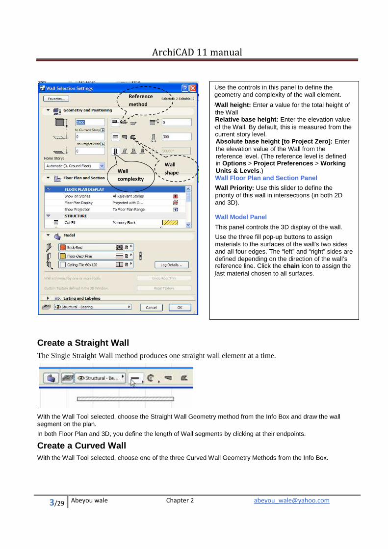
Use the controls in this panel to define the geometry and complexity of the wall element.
• Wall height: Enter a value for the total height of the Wall
•
Relative base height: Enter the elevation value of the Wall. By default, this is measured from the current story level.
•
Absolute base height [to Project Zero]: Enter the elevation value of the Wall from the reference level. (The reference level is defined in Options > Project Preferences > Working Units & Levels.) Wall Floor Plan and Section Panel
Wall Priority: Use this slider to define the priority of this wall in intersections (in both 2D and 3D). Wall Model Panel
This panel controls the 3D display of the wall.
Use the three fill pop-up buttons to assign materials to the surfaces of the wall’s two sides and all four edges. The “left” and “right” sides are defined depending on the direction of the wall’s reference line. Click the chain icon to assign the last material chosen to all surfaces.
Reference
method
Wall
shape Wall
complexity
ArchiCAD 11 manual
4/29 Abeyou wale Chapter 2 [email protected]
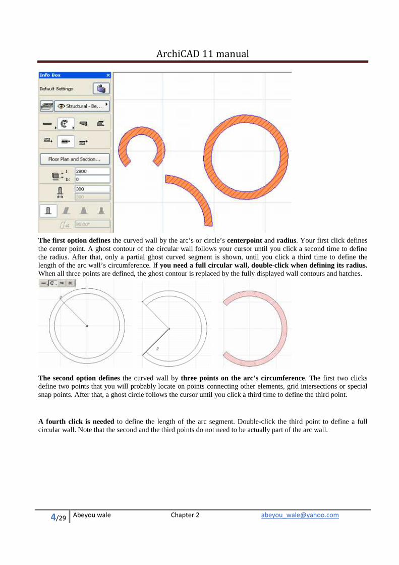
The first option defines the curved wall by the arc’s or circle’s centerpoint and radius. Your first click defines the center point. A ghost contour of the circular wall follows your cursor until you click a second time to define the radius. After that, only a partial ghost curved segment is shown, until you click a third time to define the length of the arc wall’s circumference. If you need a full circular wall, double-click when defining its radius.When all three points are defined, the ghost contour is replaced by the fully displayed wall contours and hatches.
The second option defines the curved wall by three points on the arc’s circumference. The first two clicks define two points that you will probably locate on points connecting other elements, grid intersections or special snap points. After that, a ghost circle follows the cursor until you click a third time to define the third point.
A fourth click is needed to define the length of the arc segment. Double-click the third point to define a full circular wall. Note that the second and the third points do not need to be actually part of the arc wall.
ArchiCAD 11 manual
5/29 Abeyou wale Chapter 2 [email protected]
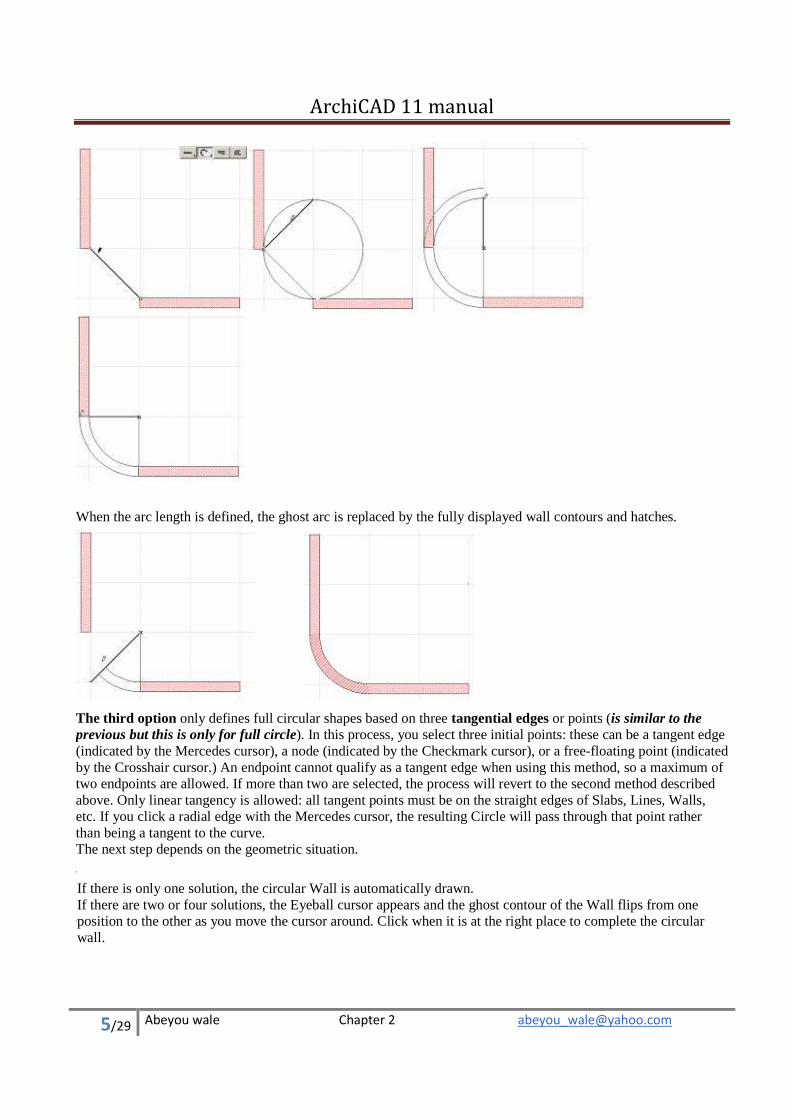
When the arc length is defined, the ghost arc is replaced by the fully displayed wall contours and hatches.
The third option only defines full circular shapes based on three tangential edges or points (is similar to the previous but this is only for full circle). In this process, you select three initial points: these can be a tangent edge (indicated by the Mercedes cursor), a node (indicated by the Checkmark cursor), or a free-floating point (indicated by the Crosshair cursor.) An endpoint cannot qualify as a tangent edge when using this method, so a maximum of two endpoints are allowed. If more than two are selected, the process will revert to the second method described above. Only linear tangency is allowed: all tangent points must be on the straight edges of Slabs, Lines, Walls, etc. If you click a radial edge with the Mercedes cursor, the resulting Circle will pass through that point rather than being a tangent to the curve. The next step depends on the geometric situation.
• If there is only one solution, the circular Wall is automatically drawn.
•
If there are two or four solutions, the Eyeball cursor appears and the ghost contour of the Wall flips from one position to the other as you move the cursor around. Click when it is at the right place to complete the circular wall.
ArchiCAD 11 manual
6/29 Abeyou wale Chapter 2 [email protected]
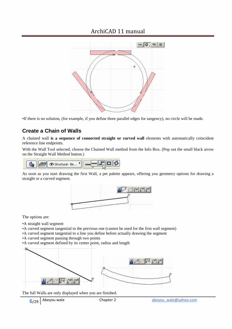
• If there is no solution, (for example, if you define three parallel edges for tangency), no circle will be made.
Create a Chain of Walls A chained wall is a sequence of connected straight or curved wall elements with automatically coincident reference line endpoints.
With the Wall Tool selected, choose the Chained Wall method from the Info Box. (Pop out the small black arrow on the Straight Wall Method button.)
As soon as you start drawing the first Wall, a pet palette appears, offering you geometry options for drawing a straight or a curved segment.
The options are:
• A straight wall segment • A curved segment tangential to the previous one (cannot be used for the first wall segment) • A curved segment tangential to a line you define before actually drawing the segment • A curved segment passing through two points • A curved segment defined by its center point, radius and length
The full Walls are only displayed when you are finished.
ArchiCAD 11 manual
7/29 Abeyou wale Chapter 2 [email protected]
•
• Clicking the Cancel button in the Control Box or hitting the Delete key at any time during drafting will abort the process, and no elements will be created.
• Choosing Edit > Undo command will remove the entire new chain of Walls, not just the last segment. • Hitting the Backspace key allows you to undo the previous segment and continue the creation of the Wall
chain. • If you change the Wall’s attributes in the Info Box during the creation process, all created Wall segments will
have the modified attributes (reference line position, line type, fill color, material, etc.). • If necessary, you can switch methods on the fly with the pet palette. • If the Edit > Grouping > Autogroup function is switched on, the chained Wall segments will be created as
part of a group.
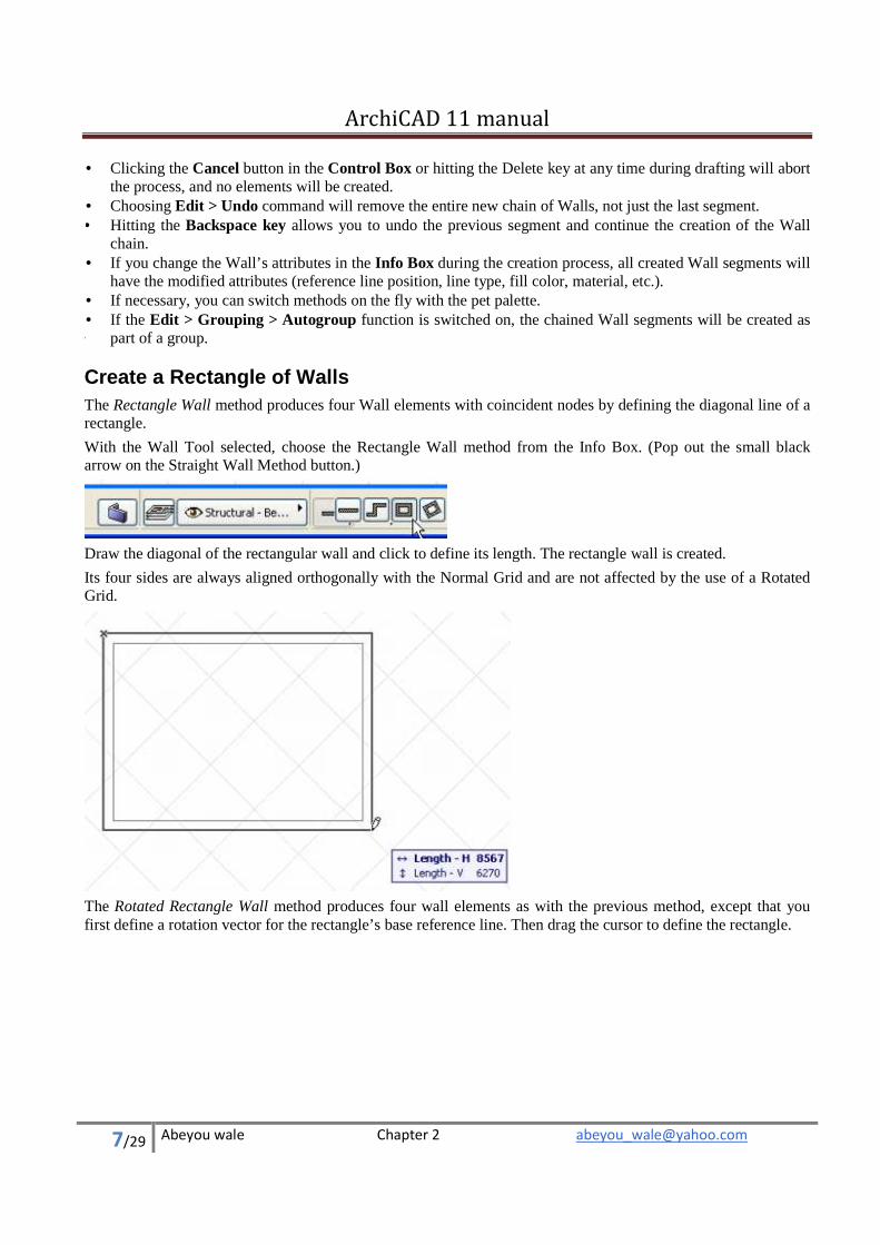
Create a Rectangle of Walls The Rectangle Wall method produces four Wall elements with coincident nodes by defining the diagonal line of a rectangle.
With the Wall Tool selected, choose the Rectangle Wall method from the Info Box. (Pop out the small black arrow on the Straight Wall Method button.)
Draw the diagonal of the rectangular wall and click to define its length. The rectangle wall is created.
Its four sides are always aligned orthogonally with the Normal Grid and are not affected by the use of a Rotated Grid.
The Rotated Rectangle Wall method produces four wall elements as with the previous method, except that you first define a rotation vector for the rectangle’s base reference line. Then drag the cursor to define the rectangle.
ArchiCAD 11 manual
8/29 Abeyou wale Chapter 2 [email protected]
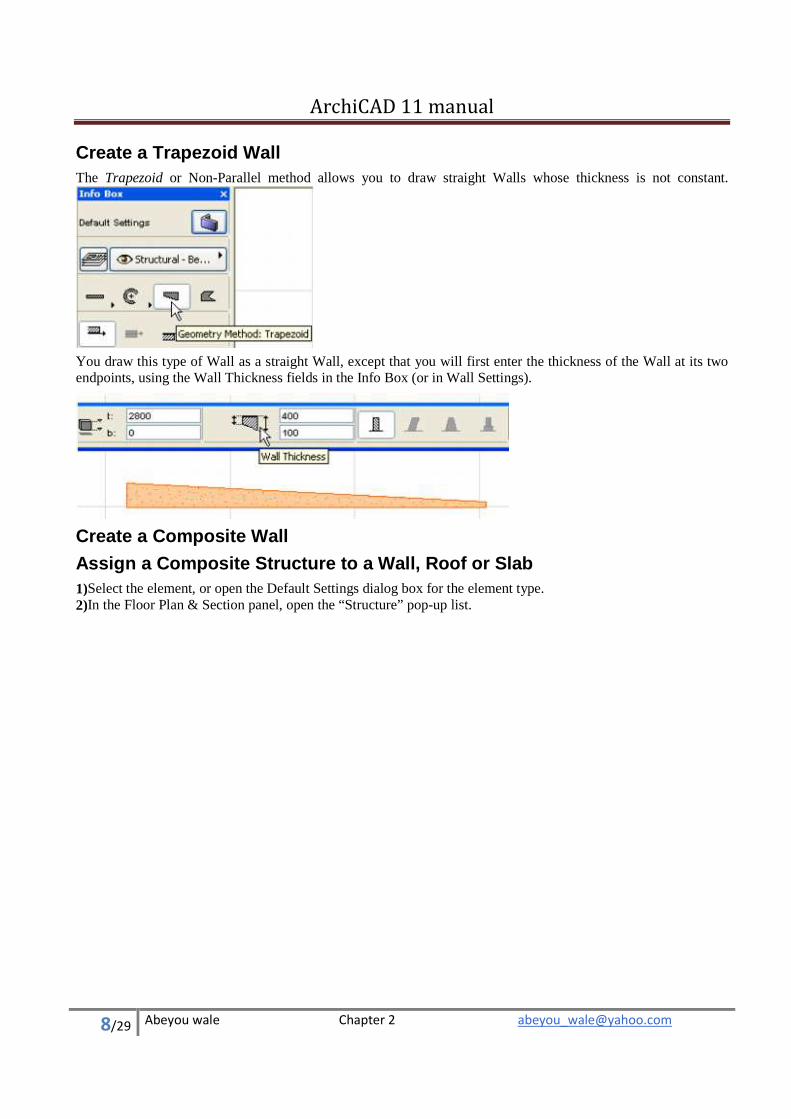
Create a Trapezoid Wall The Trapezoid or Non-Parallel method allows you to draw straight Walls whose thickness is not constant.
You draw this type of Wall as a straight Wall, except that you will first enter the thickness of the Wall at its two endpoints, using the Wall Thickness fields in the Info Box (or in Wall Settings).
Create a Composite Wall
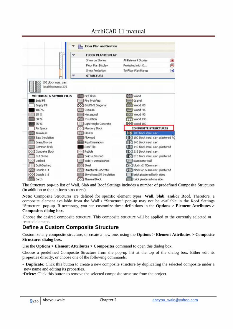
Assign a Composite Structure to a Wall, Roof or Slab 1) Select the element, or open the Default Settings dialog box for the element type. 2) In the Floor Plan & Section panel, open the “Structure” pop-up list.
ArchiCAD 11 manual
9/29 Abeyou wale Chapter 2 [email protected]
The Structure pop-up list of Wall, Slab and Roof Settings includes a number of predefined Composite Structures (in addition to the uniform structures).
Note: Composite Structures are defined for specific element types: Wall, Slab, and/or Roof. Therefore, a composite element available from the Wall’s “Structure” pop-up may not be available in the Roof Settings “Structure” pop-up. If necessary, you can customize these definitions in the Options > Element Attributes > Composites dialog box.
Choose the desired composite structure. This composite structure will be applied to the currently selected or created element.
Define a Custom Composite Structure Customize any composite structure, or create a new one, using the Options > Element Attributes > Composite Structures dialog box.
Use the Options > Element Attributes > Composites command to open this dialog box.
Choose a predefined Composite Structure from the pop-up list at the top of the dialog box. Either edit its properties directly, or choose one of the following commands:
• Duplicate: Click this button to create a new composite structure by duplicating the selected composite under a new name and editing its properties.
• Delete: Click this button to remove the selected composite structure from the project.
ArchiCAD 11 manual
10/29 Abeyou wale Chapter 2 [email protected]
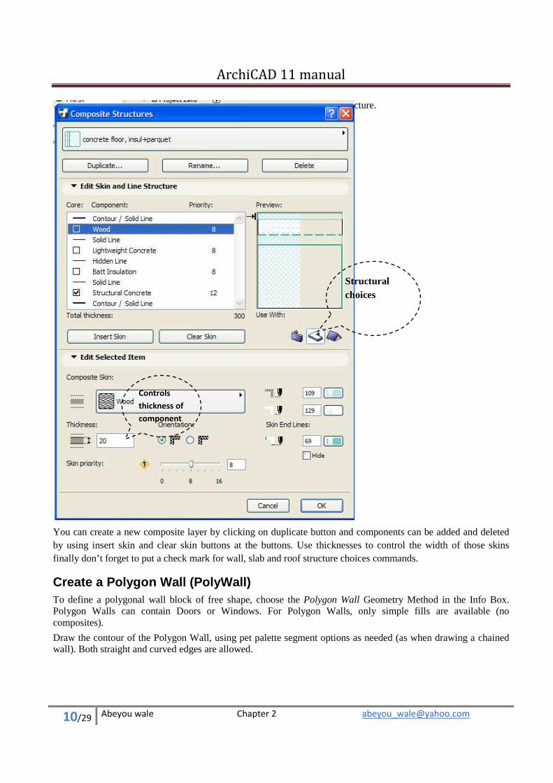
You can create a new composite layer by clicking on duplicate button and components can be added and deleted by using insert skin and clear skin buttons at the buttons. Use thicknesses to control the width of those skins finally don’t forget to put a check mark for wall, slab and roof structure choices commands.
Create a Polygon Wall (PolyWall) To define a polygonal wall block of free shape, choose the Polygon Wall Geometry Method in the Info Box. Polygon Walls can contain Doors or Windows. For Polygon Walls, only simple fills are available (no composites).
Draw the contour of the Polygon Wall, using pet palette segment options as needed (as when drawing a chained wall). Both straight and curved edges are allowed.
•Rename: Click this button to rename the currently selected composite structure.
Controls
thickness of
component
Structural choices
ArchiCAD 11 manual
11/29 Abeyou wale Chapter 2 [email protected]
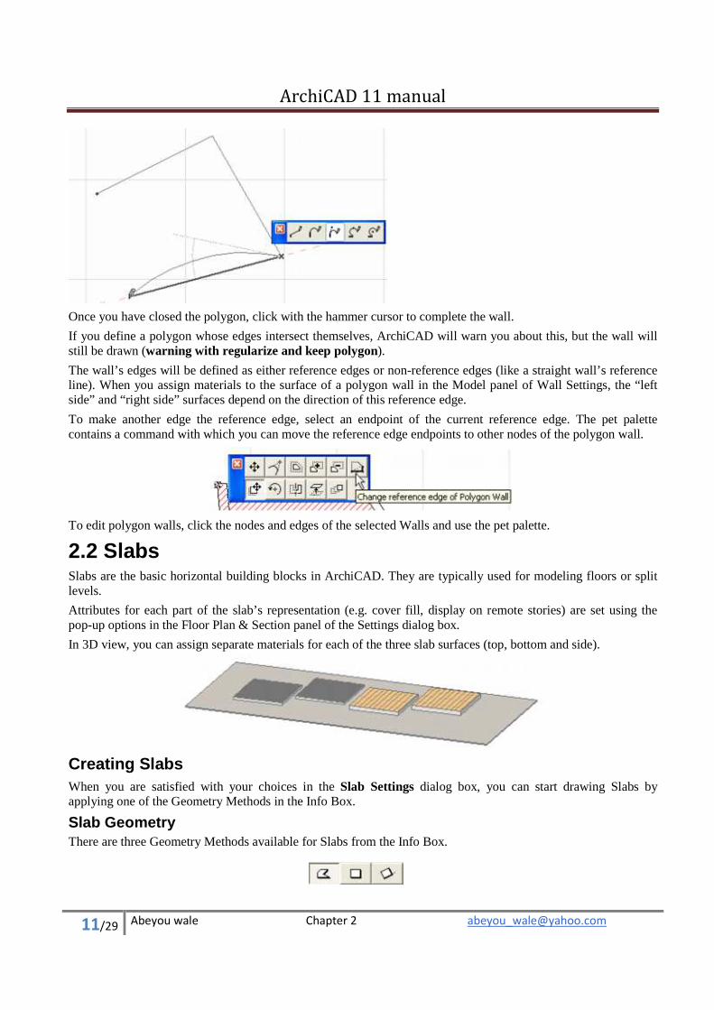
Once you have closed the polygon, click with the hammer cursor to complete the wall.
If you define a polygon whose edges intersect themselves, ArchiCAD will warn you about this, but the wall will still be drawn (warning with regularize and keep polygon).
The wall’s edges will be defined as either reference edges or non-reference edges (like a straight wall’s reference line). When you assign materials to the surface of a polygon wall in the Model panel of Wall Settings, the “left side” and “right side” surfaces depend on the direction of this reference edge.
To make another edge the reference edge, select an endpoint of the current reference edge. The pet palette contains a command with which you can move the reference edge endpoints to other nodes of the polygon wall.
To edit polygon walls, click the nodes and edges of the selected Walls and use the pet palette.
2.2 Slabs Slabs are the basic horizontal building blocks in ArchiCAD. They are typically used for modeling floors or split levels.
Attributes for each part of the slab’s representation (e.g. cover fill, display on remote stories) are set using the pop-up options in the Floor Plan & Section panel of the Settings dialog box.
In 3D view, you can assign separate materials for each of the three slab surfaces (top, bottom and side).
Creating Slabs When you are satisfied with your choices in the Slab Settings dialog box, you can start drawing Slabs by applying one of the Geometry Methods in the Info Box.
Slab Geometry There are three Geometry Methods available for Slabs from the Info Box.
ArchiCAD 11 manual
12/29 Abeyou wale Chapter 2 [email protected]
• With the first icon on the left, you can create a Polygonal Slab. Just like for Walls, the pet palette appears and allows you to draw straight and curved segments for the Slab’s outline.
If the Slab’s polygon intersects itself, a warning appears, but the Slab will still be drawn.
A self-intersecting Slab polygon will be fixed automatically if you edit the polygon later using any of the pet palette’s editing methods (warning with regularize and keep polygon).
•
The second and third icon allow you to create a Rectangular or a Rotated Rectangular Slab. The rectangle is defined by placing two opposing corner nodes. A rectangle Slab is always aligned orthogonally with the normal grid. The Rotated Rectangular method requires that you first define a rotation vector.
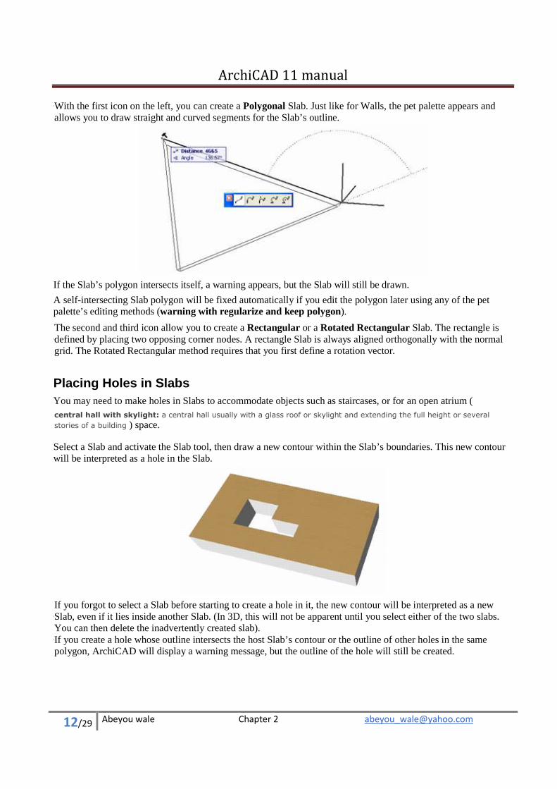
Placing Holes in Slabs You may need to make holes in Slabs to accommodate objects such as staircases, or for an open atrium ( central hall with skylight: a central hall usually with a glass roof or skylight and extending the full height or several
stories of a building ) space.
Select a Slab and activate the Slab tool, then draw a new contour within the Slab’s boundaries. This new contour will be interpreted as a hole in the Slab.
•
If you forgot to select a Slab before starting to create a hole in it, the new contour will be interpreted as a new Slab, even if it lies inside another Slab. (In 3D, this will not be apparent until you select either of the two slabs. You can then delete the inadvertently created slab). • If you create a hole whose outline intersects the host Slab’s contour or the outline of other holes in the same polygon, ArchiCAD will display a warning message, but the outline of the hole will still be created.
ArchiCAD 11 manual
13/29 Abeyou wale Chapter 2 [email protected]
2.3 Columns Columns in ArchiCAD are made up of two components: the load-bearing core and the optional veneer used to simulate fire proofing or any kind of sheathing around the core. The Column’s section can be rectangular or circular, or they can be complex. Columns can stand free, or they can be smartly connected to walls. The column’s axis can be either vertical or slanted.
Double-click the Column tool icon to open the Column Settings dialog box and set your preferences.
Crossing Symbol The Floor Plan Symbol options (in Column Tool Settings, Floor Plan and Section Panel) refer to the column’s crossing symbol (Plain, Slash, X, or Crosshair). The display of all column floor plan symbols in the project can be turned on or off with the Show Column Symbol checkbox in Document > Set Model View > Model View Options.
Creating Columns Use the Column tool to create new columns in either the Floor Plan or the 3D Window.
Choose the desired column attributes and geometry from the Column Settings Dialog box, and then click to place the column into the project.
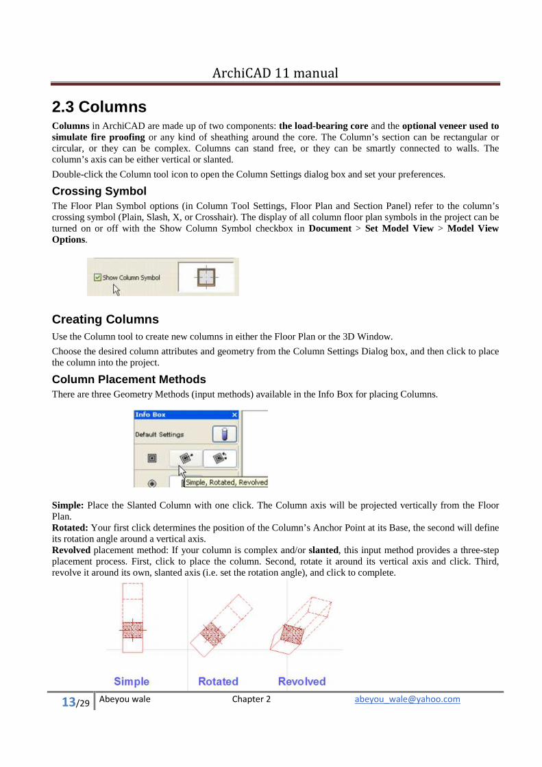
Column Placement Methods There are three Geometry Methods (input methods) available in the Info Box for placing Columns.
Simple: Place the Slanted Column with one click. The Column axis will be projected vertically from the Floor Plan. Rotated: Your first click determines the position of the Column’s Anchor Point at its Base, the second will define its rotation angle around a vertical axis. Revolved placement method: If your column is complex and/or slanted, this input method provides a three-step placement process. First, click to place the column. Second, rotate it around its vertical axis and click. Third, revolve it around its own, slanted axis (i.e. set the rotation angle), and click to complete.
ArchiCAD 11 manual
14/29 Abeyou wale Chapter 2 [email protected]
Columns and Other Elements
Beams and Columns: When a Beam crosses a Column, the element of lower priority is cut in 3D.
• Column Priority vs. Beams is a global setting applicable to all columns; it is set in Options > Project Preferences > Construction Elements. • Beam Priority is set in the Beam Tool Settings dialog box (Floor Plan and Section Panel).
2.4 Beams ArchiCAD Beams are horizontal or inclined construction elements with vertical end faces. They can be rectangular or complex in shape.
Beam Reference Axis Each Beam possesses a reference axis (center line) which serves the precise connection of Beams for clean intersections and establishes hotspots and edges for selecting, moving and transforming Beams. Its direction determines the beam’s “left” and “right” surfaces for the purpose of applying materials in the Model Panel of Beam Tool Settings.
The direction of the reference axis follows your cursor as you drag it to draw the beam. (To see the arrow on the beam that indicates the axis direction, turn on View > On-Screen View Options > Wall and Beam Reference Lines.)
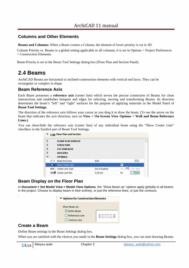
You can show/hide the reference axis (center line) of any individual beam using the “Show Center Line” checkbox in the Symbol part of Beam Tool Settings.
Beam Display on the Floor Plan
In Document > Set Model View > Model View Options, the “Show Beam as” options apply globally to all beams in the project. Choose to display beam in their entirety, or just the reference lines, or just the contours.
.
Create a Beam Define Beam settings in the Beam Settings dialog box.
When you are satisfied with the choices you made in the Beam Settings dialog box, you can start drawing Beams.
ArchiCAD 11 manual
15/29 Abeyou wale Chapter 2 [email protected]
New Beams can be created in either the Floor Plan or the 3D Window.
Beam Geometry
There are four Geometry Methods available for drawing Beams.
Choose one of these Geometry Methods from the Info Box.
• The Single Beam method produces a beam element by clicking twice, at the reference line’s starting point and endpoint.
• The PolyBeam method creates a sequence of connected beam elements with automatically coincident reference line endpoints. The process for drawing chained Beams is the same as for Walls.
Only straight beam segments can be drawn when creating a PolyBeam. When you click to end the definition of the first Beam, you automatically start drawing the second one, and so on, until you double-click to finish drawing the chained Beams.
• The Rectangle Beam produces four beam elements with coincident nodes and aligned to the X and Y axes. Define the rectangle by clicking the starting point and the endpoint of one of its diagonal lines.
• The Rotated Rectangle Beam method produces four beam elements with coincident nodes, the first side of the rectangle being defined by the first two mouse clicks at their endpoints and the perpendicular side defined by the third mouse click.
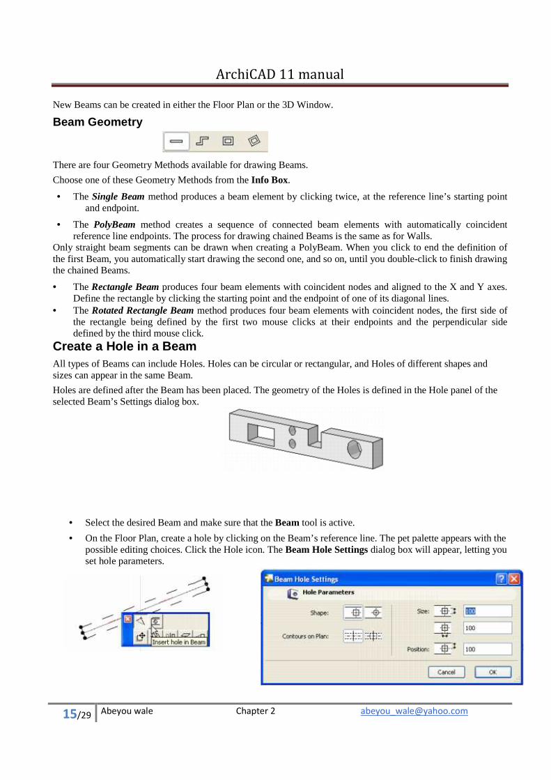
Create a Hole in a Beam All types of Beams can include Holes. Holes can be circular or rectangular, and Holes of different shapes and sizes can appear in the same Beam.
Holes are defined after the Beam has been placed. The geometry of the Holes is defined in the Hole panel of the selected Beam’s Settings dialog box.
• Select the desired Beam and make sure that the Beam tool is active.
• On the Floor Plan, create a hole by clicking on the Beam’s reference line. The pet palette appears with the possible editing choices. Click the Hole icon. The Beam Hole Settings dialog box will appear, letting you set hole parameters.
ArchiCAD 11 manual
16/29 Abeyou wale Chapter 2 [email protected]
Click OK to apply the beam hole settings; the Hole will immediately appear in the Beam.
In the 3D window, you can access the pet palette by clicking the Mercedes cursor on a top edge of the selected Beam element.
Roofs About Roofs ArchiCAD’s flexible Roofs have can be used to create both standard and abstract 3D shapes meeting a wide variety of needs.
The roof’s elevation is measured by the elevation of the pivot line, a horizontal non-printing line that you draw when creating the roof.
� In most cases, you will want the pivot line of the roof to coincide with a wall Reference Line or a slab edge.
Note: You can hide all pivot lines with the appropriate control in View > On-Screen View Options.
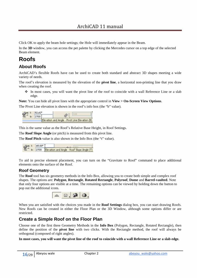
The Pivot Line elevation is shown in the roof’s info box (the “b” value).
This is the same value as the Roof’s Relative Base Height, in Roof Settings.
The Roof Slope Angle (or pitch) is measured from this pivot line.
The Roof Pitch value is also shown in the Info Box (the “t” value).
To aid in precise element placement, you can turn on the “Gravitate to Roof” command to place additional elements onto the surface of the Roof.
Roof Geometry The Roof tool has six geometry methods in the Info Box, allowing you to create both simple and complex roof shapes. The options are: Polygon, Rectangle, Rotated Rectangle, Polyroof, Dome and Barrel-vaulted. Note that only four options are visible at a time. The remaining options can be viewed by holding down the button to pop out the additional icons.
When you are satisfied with the choices you made in the Roof Settings dialog box, you can start drawing Roofs. New Roofs can be created in either the Floor Plan or the 3D Window, although some options differ or are restricted.
Create a Simple Roof on the Floor Plan Choose one of the first three Geometry Methods in the Info Box (Polygon, Rectangle, Rotated Rectangle), then define the position of the pivot line with two clicks. With the Rectangle method, the roof will always be orthogonal (composed of right angles).
In most cases, you will want the pivot line of the roof to coincide with a wall Reference Line or a slab edge.
ArchiCAD 11 manual
17/29 Abeyou wale Chapter 2 [email protected]
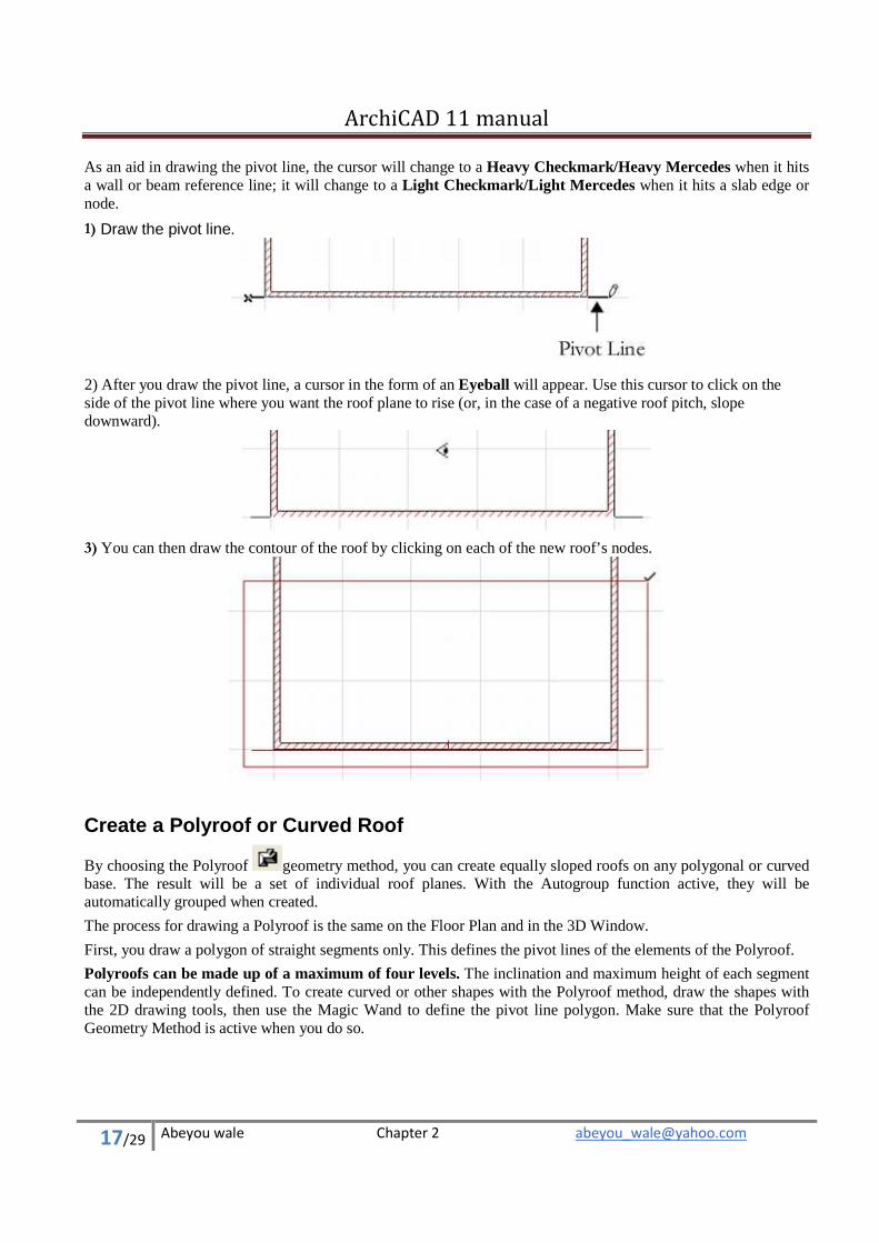
As an aid in drawing the pivot line, the cursor will change to a Heavy Checkmark/Heavy Mercedes when it hits a wall or beam reference line; it will change to a Light Checkmark/Light Mercedes when it hits a slab edge or node.
1) Draw the pivot line.
2) After you draw the pivot line, a cursor in the form of an Eyeball will appear. Use this cursor to click on the side of the pivot line where you want the roof plane to rise (or, in the case of a negative roof pitch, slope downward).
3) You can then draw the contour of the roof by clicking on each of the new roof’s nodes.
Create a Polyroof or Curved Roof
By choosing the Polyroof geometry method, you can create equally sloped roofs on any polygonal or curved base. The result will be a set of individual roof planes. With the Autogroup function active, they will be automatically grouped when created.
The process for drawing a Polyroof is the same on the Floor Plan and in the 3D Window.
First, you draw a polygon of straight segments only. This defines the pivot lines of the elements of the Polyroof.
Polyroofs can be made up of a maximum of four levels. The inclination and maximum height of each segment can be independently defined. To create curved or other shapes with the Polyroof method, draw the shapes with the 2D drawing tools, then use the Magic Wand to define the pivot line polygon. Make sure that the Polyroof Geometry Method is active when you do so.
ArchiCAD 11 manual
18/29 Abeyou wale Chapter 2 [email protected]
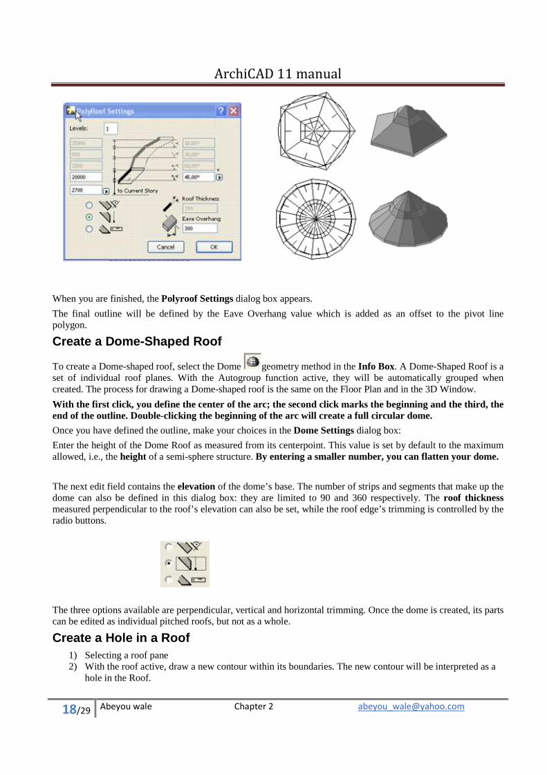
When you are finished, the Polyroof Settings dialog box appears.
The final outline will be defined by the Eave Overhang value which is added as an offset to the pivot line polygon.
Create a Dome-Shaped Roof
To create a Dome-shaped roof, select the Dome geometry method in the Info Box. A Dome-Shaped Roof is a set of individual roof planes. With the Autogroup function active, they will be automatically grouped when created. The process for drawing a Dome-shaped roof is the same on the Floor Plan and in the 3D Window.
With the first click, you define the center of the arc; the second click marks the beginning and the third, the end of the outline. Double-clicking the beginning of the arc will create a full circular dome.
Once you have defined the outline, make your choices in the Dome Settings dialog box:
Enter the height of the Dome Roof as measured from its centerpoint. This value is set by default to the maximum allowed, i.e., the height of a semi-sphere structure. By entering a smaller number, you can flatten your dome.
The next edit field contains the elevation of the dome’s base. The number of strips and segments that make up the dome can also be defined in this dialog box: they are limited to 90 and 360 respectively. The roof thickness measured perpendicular to the roof’s elevation can also be set, while the roof edge’s trimming is controlled by the radio buttons.
The three options available are perpendicular, vertical and horizontal trimming. Once the dome is created, its parts can be edited as individual pitched roofs, but not as a whole.
Create a Hole in a Roof
1) Selecting a roof pane 2) With the roof active, draw a new contour within its boundaries. The new contour will be interpreted as a
hole in the Roof.
ArchiCAD 11 manual
19/29 Abeyou wale Chapter 2 [email protected]
Note: If you create a hole whose outline intersects the host Roof’s contour or the outline of other holes in the same polygon, ArchiCAD will display a warning message, but the outline of the hole will still be created.
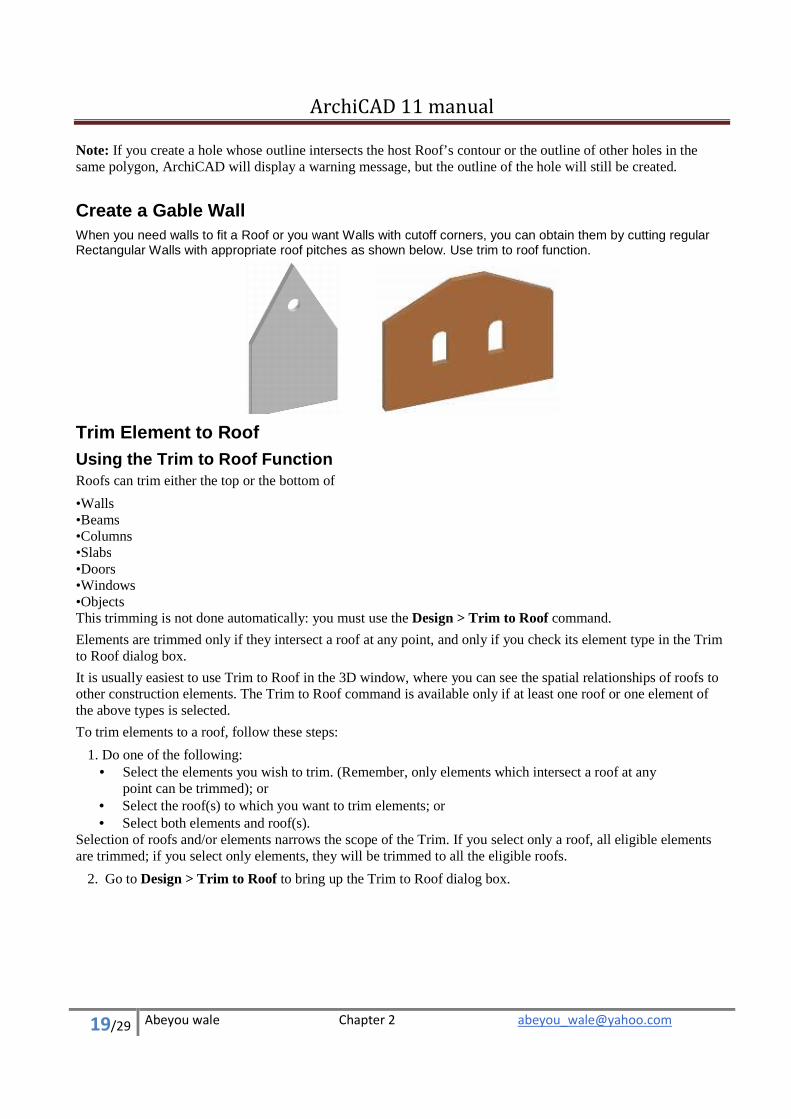
Create a Gable Wall When you need walls to fit a Roof or you want Walls with cutoff corners, you can obtain them by cutting regular Rectangular Walls with appropriate roof pitches as shown below. Use trim to roof function.
Trim Element to Roof Using the Trim to Roof Function Roofs can trim either the top or the bottom of
• Walls • Beams • Columns • Slabs • Doors • Windows • Objects This trimming is not done automatically: you must use the Design > Trim to Roof command.
Elements are trimmed only if they intersect a roof at any point, and only if you check its element type in the Trim to Roof dialog box.
It is usually easiest to use Trim to Roof in the 3D window, where you can see the spatial relationships of roofs to other construction elements. The Trim to Roof command is available only if at least one roof or one element of the above types is selected.
To trim elements to a roof, follow these steps:
1. Do one of the following:
• Select the elements you wish to trim. (Remember, only elements which intersect a roof at any point can be trimmed); or
• Select the roof(s) to which you want to trim elements; or • Select both elements and roof(s).
Selection of roofs and/or elements narrows the scope of the Trim. If you select only a roof, all eligible elements are trimmed; if you select only elements, they will be trimmed to all the eligible roofs.
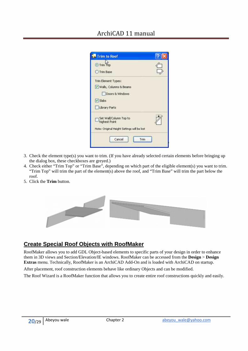
2. Go to Design > Trim to Roof to bring up the Trim to Roof dialog box.
ArchiCAD 11 manual
20/29 Abeyou wale Chapter 2 [email protected]
3. Check the element type(s) you want to trim. (If you have already selected certain elements before bringing up
the dialog box, these checkboxes are greyed.) 4. Check either “Trim Top” or “Trim Base”, depending on which part of the eligible element(s) you want to trim.
“Trim Top” will trim the part of the element(s) above the roof, and “Trim Base” will trim the part below the roof.
5. Click the Trim button.
Create Special Roof Objects with RoofMaker RoofMaker allows you to add GDL Object-based elements to specific parts of your design in order to enhance them in 3D views and Section/Elevation/IE windows. RoofMaker can be accessed from the Design > Design Extras menu. Technically, RoofMaker is an ArchiCAD Add-On and is loaded with ArchiCAD on startup.
After placement, roof construction elements behave like ordinary Objects and can be modified.
The Roof Wizard is a RoofMaker function that allows you to create entire roof constructions quickly and easily.
ArchiCAD 11 manual
21/29 Abeyou wale Chapter 2 [email protected]
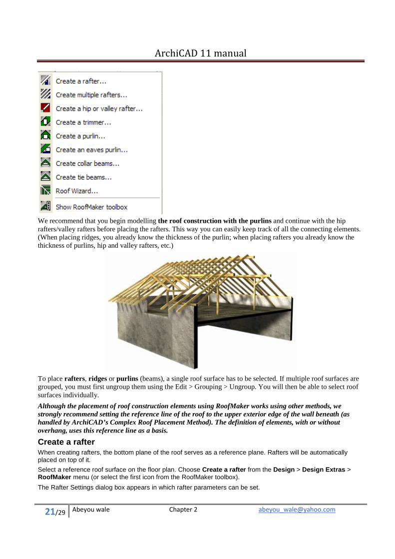
We recommend that you begin modelling the roof construction with the purlins and continue with the hip rafters/valley rafters before placing the rafters. This way you can easily keep track of all the connecting elements. (When placing ridges, you already know the thickness of the purlin; when placing rafters you already know the thickness of purlins, hip and valley rafters, etc.)
To place rafters, ridges or purlins (beams), a single roof surface has to be selected. If multiple roof surfaces are grouped, you must first ungroup them using the Edit > Grouping > Ungroup. You will then be able to select roof surfaces individually.
Although the placement of roof construction elements using RoofMaker works using other methods, we strongly recommend setting the reference line of the roof to the upper exterior edge of the wall beneath (as handled by ArchiCAD’s Complex Roof Placement Method). The definition of elements, with or without overhang, uses this reference line as a basis.
Create a rafter When creating rafters, the bottom plane of the roof serves as a reference plane. Rafters will be automatically placed on top of it.
Select a reference roof surface on the floor plan. Choose Create a rafter from the Design > Design Extras > RoofMaker menu (or select the first icon from the RoofMaker toolbox).
The Rafter Settings dialog box appears in which rafter parameters can be set.
ArchiCAD 11 manual
22/29 Abeyou wale Chapter 2 [email protected]
Clicking OK returns you to the floor plan with the reference roof surface still selected. Click inside the selected roof surface. (If you click outside, an error message appears.)
A rafter is placed with its axis going through the specified point. By definition, rafters are perpendicular to the reference line of the roof.
After the rafter is placed, you can select it and open its Object Settings dialog box. Among others, the parameters include profile and profile thickness. The rafter may have a rectangular (default) profile as well as I-beam, L-beam or C-beam profiles.
Create multiple rafters Select a reference roof surface on the floor plan. Choose Create multiple rafters from the Design > Design Extras > RoofMaker menu (or select the second icon from the RoofMaker toolbox.
In the Rafter Settings dialog box, set the desired parameters. You will set the same controls as for a single rafter, but the placement controls for multiple rafters are also active.
Clicking OK returns you to the floor plan with the reference roof surface still selected. Click twice inside the selected roof surface to define a placement line. (If you click outside, an error message appears.)
Several rafters are placed along the placement line, with the axis of the first rafter going through the point defined with the first click, and the axis of the last rafter going through the point defined with the second click. By definition, rafters are perpendicular to the reference line of the roof.
Create hip or valley rafter The hip rafter usually lies between two neighboring roof polygons. Select the roof surface where the hip rafter connects to a purlin instead of another hip rafter; other methods may cause errors.
Choose Create a hip rafter or valley rafter from the Design > Design Extras > RoofMaker menu (or click the third icon of the RoofMaker toolbox). The Hip or Valley Rafter Settings dialog box opens.
For more information, see Create a Hip or Valley Rafter.
After adjusting those settings, click OK to return to the floor plan with the reference roof surface still selected. Click along one of the edges of the selected roof that is NOT parallel or perpendicular to the reference line.
A Hip or a Valley Rafter (or a Valley Rafter without Overhang) is placed along the specified edge of the roof, depending on the position of the edge to the roof’s reference line.
Hip and Valley Rafters can also be placed with two roof surfaces selected previously. It is then not necessary to click afterwards to specify an edge; the object will be placed along the common edge of the two surfaces. The difference between the two methods lies in the shape of the resulting objects; the top cut in the latter method makes the object suitable for steeple type roofs.
Create a trimmer In order to place a trimmer, you must first select the two rafters the trimmer is going to be placed between. The two rafters have to be within the same roof polygon. (This also means that they have the same pitch angle and they are both perpendicular to the reference line of the roof.)
Choose Create a Trimmer from the Design > Design Extras > RoofMaker menu. The Trimmer Settings dialog box appears.
For more information, see Create a Trimmer (or Blocking).
A trimmer is placed at the same height as the rafters. It can be vertical or rotated to a position perpendicular to the pitch angle of the roof. The 2D symbol also shows the current position.
Clicking OK, you return to the floor plan with the two rafters still selected. Click between the rafters. (If you click outside them, an error message will appear.)
A trimmer is placed between the two rafters, the axis going through the specified point. Trimmers are always parallel to the reference line of the roof and thus perpendicular to the rafters.
Create a purlin Select a reference roof surface on the floor plan and choose Create a Purlin from the Design > Design Extras > RoofMaker menu (or click the fifth icon from the RoofMaker toolbox). The Purlin Settings dialog box appears in which purlin parameters can be set.
ArchiCAD 11 manual
23/29 Abeyou wale Chapter 2 [email protected]
By default, the purlin is placed under the reference plane defined by the roof, since a purlin generally supports the rafters from below. However, an elevation value can be set for the purlin so that it can be higher or lower than the reference plane. You can also set the values for the width and the height of the cross-section.
The purlin can also be perpendicular to the rafters and be on the top of them as well. If the purlin is placed on top, the cross section height of the rafters has to be set.
Clicking OK returns you to the floor plan with the reference roof surface still selected. Click either an edge of the selected roof, or inside the roof polygon. (Clicking outside the polygon produces an error message.)
If you click on an edge, a purlin is placed with its axis along the edge. If the edge is not parallel to the reference line of the roof, the endpoints of the axis of the purlin will be at different heights - as indicated in the “Height difference” parameter of the library part - and the purlin will be inclined.
Clicking inside the roof polygon determines the position of only one side of the purlin; an additional click is needed to define the direction where the purlin extends. (For example, if you want to place a rafter in line with the interior side of a wall, first you click to the interior side and then toward the exterior.)
If you click inside the polygon, the axis of the beam will pass through the clicked point parallel to the reference line of the roof.
Create an eaves purlin Select a reference roof surface on the floor plan and choose Create an eaves purlin from the Design > Design Extras > RoofMaker menu (or click the sixth icon in the RoofMaker toolbox). The Eaves Purlin Settings dialog box appears in which eaves purlin parameters can be set.
For more information, see Create an Eaves Purlin (or Plate Beam).
This type of purlin is placed under the reference plane defined by the roof, supporting the rafters from below. However, an elevation value can be set for the eaves purlin so that it can be higher or lower than the reference plane. You can also set the values for the width and the height of the cross section.
Clicking OK returns you to the floor plan, with the reference roof surface still selected. You need to click either one of the edges of the selected roof, or inside the roof polygon. (If you click outside the polygon, an error message appears.)
If you click on an edge, the purlin is placed inside the polygon, with its side along the edge. If the edge is not parallel to the reference line of the roof, the two endpoints of the axis of the purlin will be at different heights, as indicated in the “Height difference” parameter of the library part, and the purlin will be inclined.
If you click inside the polygon, the axis of the purlin will pass through the clicked point, parallel to the reference line of the roof surface. An additional click is then needed to define the direction where the plate beam extends. (For example, if you want to place a rafter in line with the interior side of a wall, first click on the interior edge of the wall and then toward the exterior.)
There is an empty fill included in the 2D symbol of purlins because purlins usually have to cover posts placed underneath. These posts are generally displayed as a larger circle to indicate that there is some kind of supporting structure. You can use the Bring to Front and Send to Back commands to ensure the accurate positioning of elements.
Create collar beams In order to place a collar beam you must first select two rafters to place it between. The axes of the two rafters must be along the same line and meet at the top, otherwise you will get an error message.
Choose Create a collar beam from the Design > Design Extras > RoofMaker menu (or the seventh icon in the RoofMaker toolbox). The Collar Beam Settings dialog box appears in which different parameters of the collar beam can be set.
For more information, see Create Collar Beams.
A collar beam can be double- or single-sided. In addition to the dimensions of the cross-section, an elevation value must be set, calculated from the height of the insertion point of the rafters (which is usually also the height of the reference line of the roof). If the two rafters are not inserted at the same height, the collar beam is placed relative to the higher one.
Clicking OK returns you to the floor plan with the two rafters still selected. If a double-sided collar beam has been selected, it is placed automatically in the appropriate position. If a single-sided collar beam is selected, click once more to determine on which side of the rafters the collar beam will be placed.
ArchiCAD 11 manual
24/29 Abeyou wale Chapter 2 [email protected]
Create tie beams In order to place a tie beam, you must first select two rafters to place it between. The axes of the two rafters must be along the same line and meet at the top, otherwise you will get an error message.
Choose Create a tie beam from the Design > Design Extras > RoofMaker menu (or eighth icon in RoofMaker Toolbox). The Tie Beam Settings dialog box appears in which different parameters of the tie beam can be set.
For more information, see Create Tie Beams.
In addition to the dimensions of the cross section, an elevation value must be set, calculated either from Project Zero or the current story elevation.
Clicking OK returns you to the floor plan with the two rafters still selected. The tie beam is placed automatically in the appropriate position.
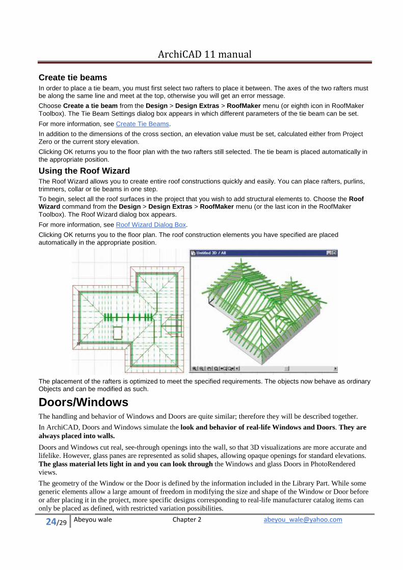
Using the Roof Wizard The Roof Wizard allows you to create entire roof constructions quickly and easily. You can place rafters, purlins, trimmers, collar or tie beams in one step.
To begin, select all the roof surfaces in the project that you wish to add structural elements to. Choose the Roof Wizard command from the Design > Design Extras > RoofMaker menu (or the last icon in the RoofMaker Toolbox). The Roof Wizard dialog box appears.
For more information, see Roof Wizard Dialog Box.
Clicking OK returns you to the floor plan. The roof construction elements you have specified are placed automatically in the appropriate position.
The placement of the rafters is optimized to meet the specified requirements. The objects now behave as ordinary Objects and can be modified as such.
Doors/Windows The handling and behavior of Windows and Doors are quite similar; therefore they will be described together.
In ArchiCAD, Doors and Windows simulate the look and behavior of real-life Windows and Doors. They are always placed into walls.
Doors and Windows cut real, see-through openings into the wall, so that 3D visualizations are more accurate and lifelike. However, glass panes are represented as solid shapes, allowing opaque openings for standard elevations. The glass material lets light in and you can look through the Windows and glass Doors in PhotoRendered views.
The geometry of the Window or the Door is defined by the information included in the Library Part. While some generic elements allow a large amount of freedom in modifying the size and shape of the Window or Door before or after placing it in the project, more specific designs corresponding to real-life manufacturer catalog items can only be placed as defined, with restricted variation possibilities.
ArchiCAD 11 manual
25/29 Abeyou wale Chapter 2 [email protected]
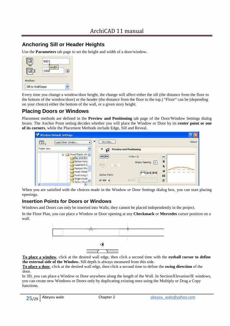
Anchoring Sill or Header Heights Use the Parameters tab page to set the height and width of a door/window.
Every time you change a window/door height, the change will affect either the sill (the distance from the floor to the bottom of the window/door) or the header (the distance from the floor to the top.) “Floor” can be (depending on your choice) either the bottom of the wall, or a given story height.
Placing Doors or Windows Placement methods are defined in the Preview and Positioning tab page of the Door/Window Settings dialog boxes. The Anchor Point setting decides whether you will place the Window or Door by its center point or one of its corners, while the Placement Methods include Edge, Sill and Reveal.
When you are satisfied with the choices made in the Window or Door Settings dialog box, you can start placing openings.
Insertion Points for Doors or Windows Windows and Doors can only be inserted into Walls; they cannot be placed independently in the project.
In the Floor Plan, you can place a Window or Door opening at any Checkmark or Mercedes cursor position on a wall.
•
To place a window, click at the desired wall edge, then click a second time with the eyeball cursor to define the external side of the Window. Sill depth is always measured from this side. • To place a door, click at the desired wall edge, then click a second time to define the swing direction of the door. In 3D, you can place a Window or Door anywhere along the length of the Wall. In Section/Elevation/IE windows, you can create new Windows or Doors only by duplicating existing ones using the Multiply or Drag a Copy functions.
ArchiCAD 11 manual
26/29 Abeyou wale Chapter 2 [email protected]
If you attempt to place a Window or Door near the end or top of a Wall, where there is not enough room to accommodate it, a dialog box will be displayed to warn you and give you the option of discarding the opening. However, you can still choose to place it.
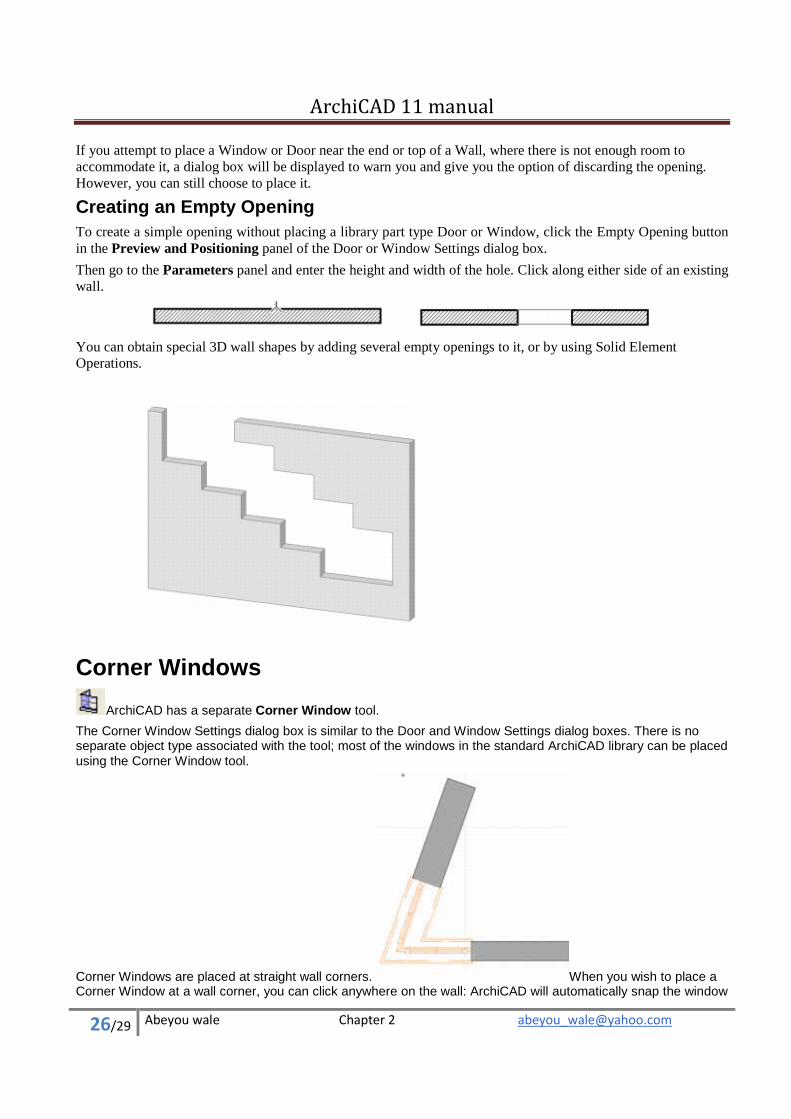
Creating an Empty Opening To create a simple opening without placing a library part type Door or Window, click the Empty Opening button in the Preview and Positioning panel of the Door or Window Settings dialog box.
Then go to the Parameters panel and enter the height and width of the hole. Click along either side of an existing wall.
You can obtain special 3D wall shapes by adding several empty openings to it, or by using Solid Element Operations.
Corner Windows
ArchiCAD has a separate Corner Window tool.
The Corner Window Settings dialog box is similar to the Door and Window Settings dialog boxes. There is no separate object type associated with the tool; most of the windows in the standard ArchiCAD library can be placed using the Corner Window tool.
Corner Windows are placed at straight wall corners. When you wish to place a Corner Window at a wall corner, you can click anywhere on the wall: ArchiCAD will automatically snap the window
ArchiCAD 11 manual
27/29 Abeyou wale Chapter 2 [email protected]
to the nearest corner of the wall and create a mirrored copy of it on the adjoining wall. The second window’s parameters and properties are identical to the first’s. Their angle and position are automatically adjusted.
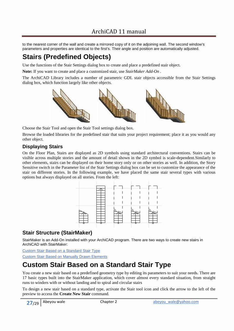
Stairs (Predefined Objects) Use the functions of the Stair Settings dialog box to create and place a predefined stair object.
Note: If you want to create and place a customized stair, use StairMaker Add-On .
The ArchiCAD Library includes a number of parametric GDL stair objects accessible from the Stair Settings dialog box, which function largely like other objects.
Choose the Stair Tool and open the Stair Tool settings dialog box.
Browse the loaded libraries for the predefined stair that suits your project requirement; place it as you would any other object.
Displaying Stairs On the Floor Plan, Stairs are displayed as 2D symbols using standard architectural conventions. Stairs can be visible across multiple stories and the amount of detail shown in the 2D symbol is scale-dependent.Similarly to other elements, stairs can be displayed on their home story only or on other stories as well. In addition, the Story Sensitive switch in the Parameter list of the Stair Settings dialog box can be set to customize the appearance of the stair on different stories. In the following example, we have placed the same stair several types with various options but always displayed on all stories. From the left:
Stair Structure (StairMaker) StairMaker is an Add-On installed with your ArchiCAD program. There are two ways to create new stairs in ArchiCAD with StairMaker:
Custom Stair Based on a Standard Stair Type
Custom Stair Based on Manually Drawn Elements
Custom Stair Based on a Standard Stair Type You create a new stair based on a predefined geometry type by editing its parameters to suit your needs. There are 17 basic types built into the StairMaker application, which cover almost every standard situation, from straight runs to winders with or without landing and to spiral and circular stairs
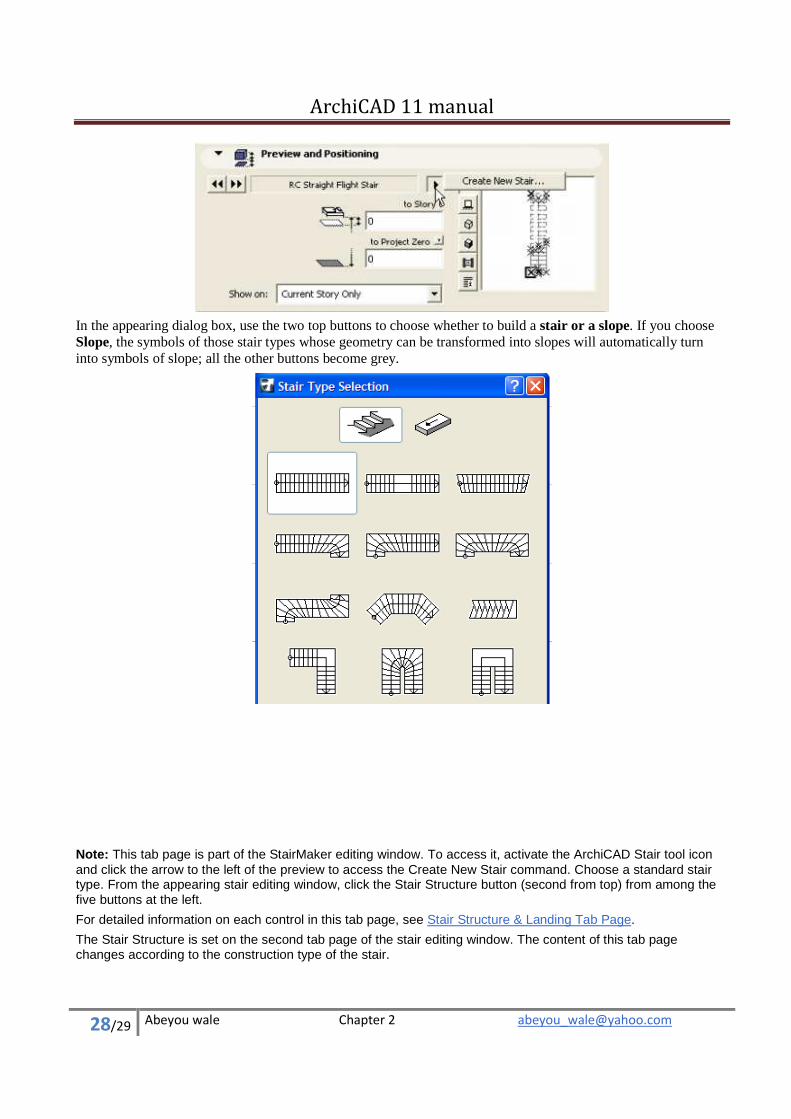
To design a new stair based on a standard type, activate the Stair tool icon and click the arrow to the left of the preview to access the Create New Stair command.
ArchiCAD 11 manual
28/29 Abeyou wale Chapter 2 [email protected]
In the appearing dialog box, use the two top buttons to choose whether to build a stair or a slope. If you choose Slope, the symbols of those stair types whose geometry can be transformed into slopes will automatically turn into symbols of slope; all the other buttons become grey.
Note: This tab page is part of the StairMaker editing window. To access it, activate the ArchiCAD Stair tool icon and click the arrow to the left of the preview to access the Create New Stair command. Choose a standard stair type. From the appearing stair editing window, click the Stair Structure button (second from top) from among the five buttons at the left.
For detailed information on each control in this tab page, see Stair Structure & Landing Tab Page.
The Stair Structure is set on the second tab page of the stair editing window. The content of this tab page changes according to the construction type of the stair.
ArchiCAD 11 manual
29/29 Abeyou wale Chapter 2 [email protected]
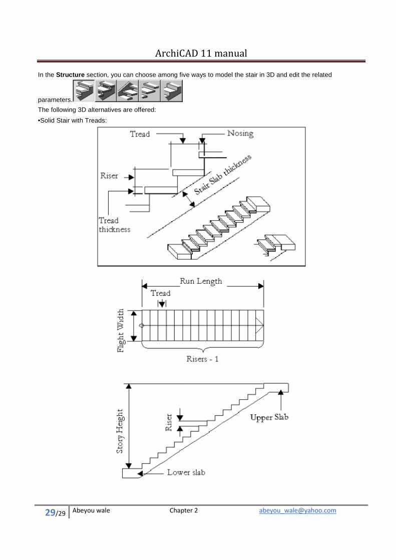
In the Structure section, you can choose among five ways to model the stair in 3D and edit the related
parameters.
The following 3D alternatives are offered:
• Solid Stair with Treads: