Embed Size (px)
Citation preview
2-1
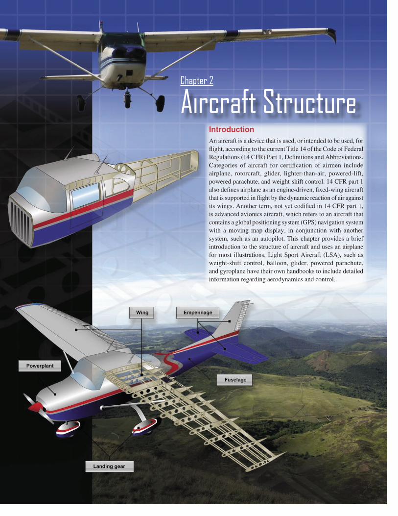
Introduction
An aircraft is a device that is used, or intended to be used, for
flight, according to the current Title 14 of the Code of Federal
Regulations (14 CFR) Part 1, Definitions and Abbreviations.
Categories of aircraft for certification of airmen include
airplane, rotorcraft, glider, lighter-than-air, powered-lift,
powered parachute, and weight-shift control. 14 CFR part 1
also defines airplane as an engine-driven, fixed-wing aircraft
that is supported in flight by the dynamic reaction of air against
its wings. Another term, not yet codified in 14 CFR part 1,
is advanced avionics aircraft, which refers to an aircraft that
contains a global positioning system (GPS) navigation system
with a moving map display, in conjunction with another
system, such as an autopilot. This chapter provides a brief
introduction to the structure of aircraft and uses an airplane
for most illustrations. Light Sport Aircraft (LSA), such as
weight-shift control, balloon, glider, powered parachute,
and gyroplane have their own handbooks to include detailed
information regarding aerodynamics and control.
Aircraft StructureChapter 2
2-2
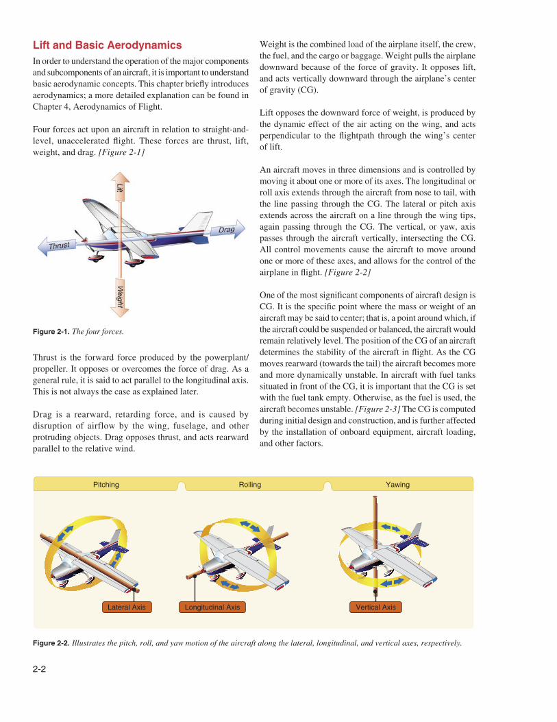
Figure 2-2. Illustrates the pitch, roll, and yaw motion of the aircraft along the lateral, longitudinal, and vertical axes, respectively.
Figure 2-1. The four forces.
Lift and Basic Aerodynamics
In order to understand the operation of the major components
and subcomponents of an aircraft, it is important to understand
basic aerodynamic concepts. This chapter briefly introduces
aerodynamics; a more detailed explanation can be found in
Chapter 4, Aerodynamics of Flight.
Four forces act upon an aircraft in relation to straight-and-
level, unaccelerated flight. These forces are thrust, lift,
weight, and drag. [Figure 2-1]
Thrust is the forward force produced by the powerplant/
propeller. It opposes or overcomes the force of drag. As a
general rule, it is said to act parallel to the longitudinal axis.
This is not always the case as explained later.
Drag is a rearward, retarding force, and is caused by
disruption of airflow by the wing, fuselage, and other
protruding objects. Drag opposes thrust, and acts rearward
parallel to the relative wind.
Weight is the combined load of the airplane itself, the crew,
the fuel, and the cargo or baggage. Weight pulls the airplane
downward because of the force of gravity. It opposes lift,
and acts vertically downward through the airplane’s center
of gravity (CG).
Lift opposes the downward force of weight, is produced by
the dynamic effect of the air acting on the wing, and acts
perpendicular to the flightpath through the wing’s center
of lift.
An aircraft moves in three dimensions and is controlled by
moving it about one or more of its axes. The longitudinal or
roll axis extends through the aircraft from nose to tail, with
the line passing through the CG. The lateral or pitch axis
extends across the aircraft on a line through the wing tips,
again passing through the CG. The vertical, or yaw, axis
passes through the aircraft vertically, intersecting the CG.
All control movements cause the aircraft to move around
one or more of these axes, and allows for the control of the
airplane in flight. [Figure 2-2]
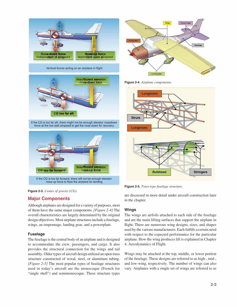
One of the most significant components of aircraft design is
CG. It is the specific point where the mass or weight of an
aircraft may be said to center; that is, a point around which, if
the aircraft could be suspended or balanced, the aircraft would
remain relatively level. The position of the CG of an aircraft
determines the stability of the aircraft in flight. As the CG
moves rearward (towards the tail) the aircraft becomes more
and more dynamically unstable. In aircraft with fuel tanks
situated in front of the CG, it is important that the CG is set
with the fuel tank empty. Otherwise, as the fuel is used, the
aircraft becomes unstable. [Figure 2-3] The CG is computed
during initial design and construction, and is further affected
by the installation of onboard equipment, aircraft loading,
and other factors.
2-3
Figure 2-4. Airplane components.
Figure 2-5. Truss-type fuselage structure.
Figure 2-3. Center of gravity (CG).
Major Components
Although airplanes are designed for a variety of purposes, most
of them have the same major components. [Figure 2-4] The
overall characteristics are largely determined by the original
design objectives. Most airplane structures include a fuselage,
wings, an empennage, landing gear, and a powerplant.
Fuselage
The fuselage is the central body of an airplane and is designed
to accommodate the crew, passengers, and cargo. It also
provides the structural connection for the wings and tail
assembly. Older types of aircraft design utilized an open truss
structure constructed of wood, steel, or aluminum tubing.
[Figure 2-5] The most popular types of fuselage structures
used in today’s aircraft are the monocoque (French for
“single shell”) and semimonocoque. These structure types
are discussed in more detail under aircraft construction later
in the chapter.
Wings
The wings are airfoils attached to each side of the fuselage
and are the main lifting surfaces that support the airplane in
flight. There are numerous wing designs, sizes, and shapes
used by the various manufacturers. Each fulfills a certain need
with respect to the expected performance for the particular
airplane. How the wing produces lift is explained in Chapter
4, Aerodynamics of Flight.
Wings may be attached at the top, middle, or lower portion
of the fuselage. These designs are referred to as high-, mid-,
and low-wing, respectively. The number of wings can also
vary. Airplanes with a single set of wings are referred to as
2-4
Figure 2-6. Monoplane (left) and biplane (right).
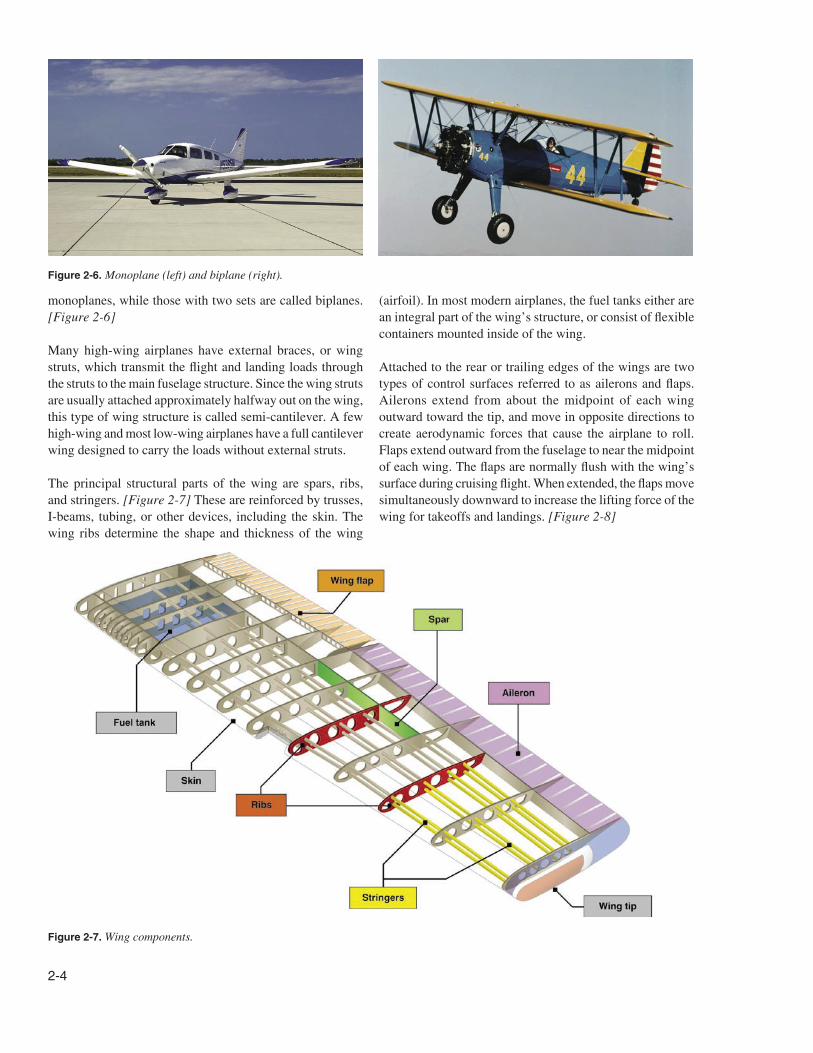
Figure 2-7. Wing components.
monoplanes, while those with two sets are called biplanes.
[Figure 2-6]
Many high-wing airplanes have external braces, or wing
struts, which transmit the flight and landing loads through
the struts to the main fuselage structure. Since the wing struts
are usually attached approximately halfway out on the wing,
this type of wing structure is called semi-cantilever. A few
high-wing and most low-wing airplanes have a full cantilever
wing designed to carry the loads without external struts.
The principal structural parts of the wing are spars, ribs,
and stringers. [Figure 2-7] These are reinforced by trusses,
I-beams, tubing, or other devices, including the skin. The
wing ribs determine the shape and thickness of the wing
(airfoil). In most modern airplanes, the fuel tanks either are
an integral part of the wing’s structure, or consist of flexible
containers mounted inside of the wing.
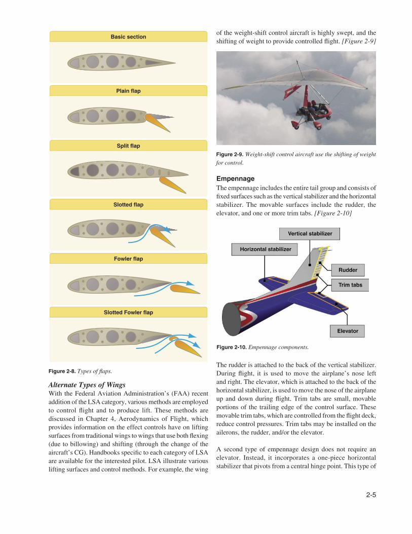
Attached to the rear or trailing edges of the wings are two
types of control surfaces referred to as ailerons and flaps.
Ailerons extend from about the midpoint of each wing
outward toward the tip, and move in opposite directions to
create aerodynamic forces that cause the airplane to roll.
Flaps extend outward from the fuselage to near the midpoint
of each wing. The flaps are normally flush with the wing’s
surface during cruising flight. When extended, the flaps move
simultaneously downward to increase the lifting force of the
wing for takeoffs and landings. [Figure 2-8]
2-5
Figure 2-8. Types of flaps.
Figure 2-9. Weight-shift control aircraft use the shifting of weight
for control.
Figure 2-10. Empennage components.
Alternate Types of Wings
With the Federal Aviation Administration’s (FAA) recent
addition of the LSA category, various methods are employed
to control flight and to produce lift. These methods are
discussed in Chapter 4, Aerodynamics of Flight, which
provides information on the effect controls have on lifting
surfaces from traditional wings to wings that use both flexing
(due to billowing) and shifting (through the change of the
aircraft’s CG). Handbooks specific to each category of LSA
are available for the interested pilot. LSA illustrate various
lifting surfaces and control methods. For example, the wing
of the weight-shift control aircraft is highly swept, and the
shifting of weight to provide controlled flight. [Figure 2-9]
Empennage
The empennage includes the entire tail group and consists of
fixed surfaces such as the vertical stabilizer and the horizontal
stabilizer. The movable surfaces include the rudder, the
elevator, and one or more trim tabs. [Figure 2-10]
The rudder is attached to the back of the vertical stabilizer.
During flight, it is used to move the airplane’s nose left
and right. The elevator, which is attached to the back of the
horizontal stabilizer, is used to move the nose of the airplane
up and down during flight. Trim tabs are small, movable
portions of the trailing edge of the control surface. These
movable trim tabs, which are controlled from the flight deck,
reduce control pressures. Trim tabs may be installed on the
ailerons, the rudder, and/or the elevator.
A second type of empennage design does not require an
elevator. Instead, it incorporates a one-piece horizontal
stabilizer that pivots from a central hinge point. This type of
2-6
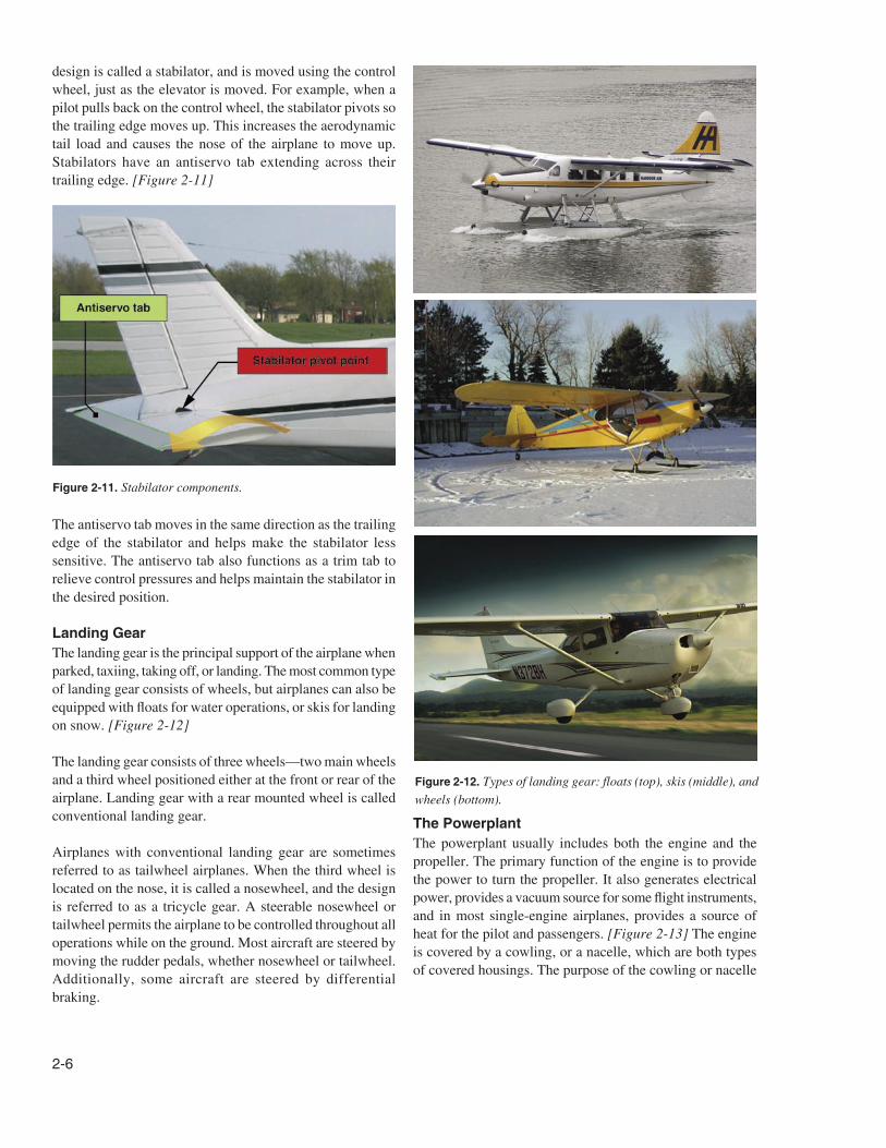
Figure 2-12. Types of landing gear: floats (top), skis (middle), and
wheels (bottom).
Figure 2-11. Stabilator components.
design is called a stabilator, and is moved using the control
wheel, just as the elevator is moved. For example, when a
pilot pulls back on the control wheel, the stabilator pivots so
the trailing edge moves up. This increases the aerodynamic
tail load and causes the nose of the airplane to move up.
Stabilators have an antiservo tab extending across their
trailing edge. [Figure 2-11]
The antiservo tab moves in the same direction as the trailing
edge of the stabilator and helps make the stabilator less
sensitive. The antiservo tab also functions as a trim tab to
relieve control pressures and helps maintain the stabilator in
the desired position.
Landing Gear
The landing gear is the principal support of the airplane when
parked, taxiing, taking off, or landing. The most common type
of landing gear consists of wheels, but airplanes can also be
equipped with floats for water operations, or skis for landing
on snow. [Figure 2-12]
The landing gear consists of three wheels—two main wheels
and a third wheel positioned either at the front or rear of the
airplane. Landing gear with a rear mounted wheel is called
conventional landing gear.
Airplanes with conventional landing gear are sometimes
referred to as tailwheel airplanes. When the third wheel is
located on the nose, it is called a nosewheel, and the design
is referred to as a tricycle gear. A steerable nosewheel or
tailwheel permits the airplane to be controlled throughout all
operations while on the ground. Most aircraft are steered by
moving the rudder pedals, whether nosewheel or tailwheel.
Additionally, some aircraft are steered by differential
braking.
The Powerplant
The powerplant usually includes both the engine and the
propeller. The primary function of the engine is to provide
the power to turn the propeller. It also generates electrical
power, provides a vacuum source for some flight instruments,
and in most single-engine airplanes, provides a source of
heat for the pilot and passengers. [Figure 2-13] The engine
is covered by a cowling, or a nacelle, which are both types
of covered housings. The purpose of the cowling or nacelle
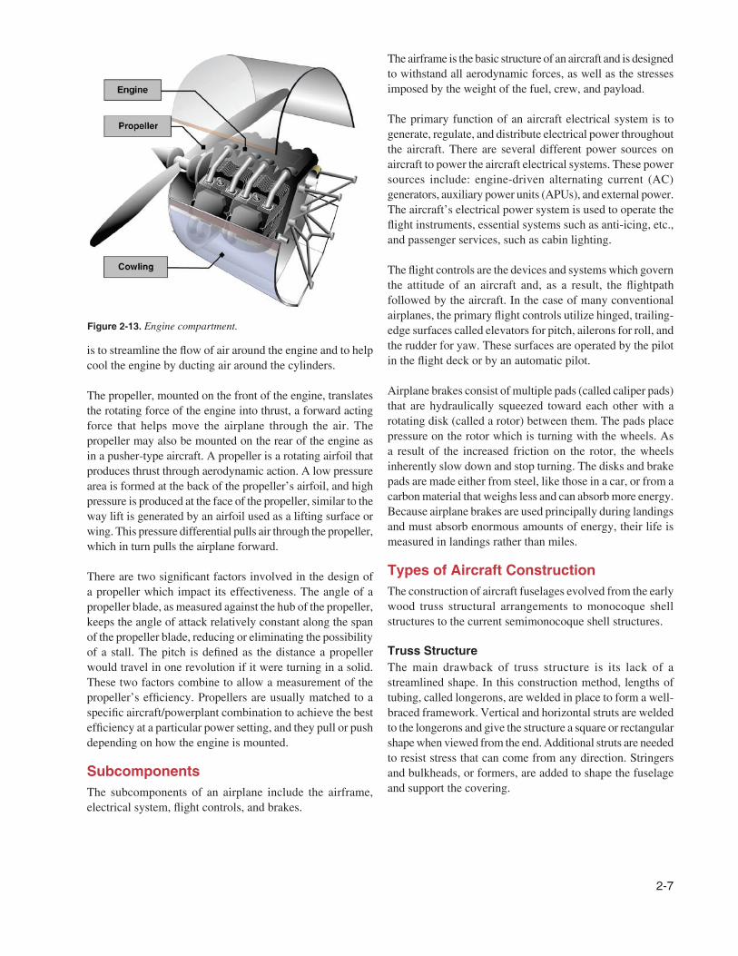
2-7
Figure 2-13. Engine compartment.
is to streamline the flow of air around the engine and to help
cool the engine by ducting air around the cylinders.
The propeller, mounted on the front of the engine, translates
the rotating force of the engine into thrust, a forward acting
force that helps move the airplane through the air. The
propeller may also be mounted on the rear of the engine as
in a pusher-type aircraft. A propeller is a rotating airfoil that
produces thrust through aerodynamic action. A low pressure
area is formed at the back of the propeller’s airfoil, and high
pressure is produced at the face of the propeller, similar to the
way lift is generated by an airfoil used as a lifting surface or
wing. This pressure differential pulls air through the propeller,
which in turn pulls the airplane forward.
There are two significant factors involved in the design of
a propeller which impact its effectiveness. The angle of a
propeller blade, as measured against the hub of the propeller,
keeps the angle of attack relatively constant along the span
of the propeller blade, reducing or eliminating the possibility
of a stall. The pitch is defined as the distance a propeller
would travel in one revolution if it were turning in a solid.
These two factors combine to allow a measurement of the
propeller’s efficiency. Propellers are usually matched to a
specific aircraft/powerplant combination to achieve the best
efficiency at a particular power setting, and they pull or push
depending on how the engine is mounted.
Subcomponents
The subcomponents of an airplane include the airframe,
electrical system, flight controls, and brakes.
The airframe is the basic structure of an aircraft and is designed
to withstand all aerodynamic forces, as well as the stresses
imposed by the weight of the fuel, crew, and payload.
The primary function of an aircraft electrical system is to
generate, regulate, and distribute electrical power throughout
the aircraft. There are several different power sources on
aircraft to power the aircraft electrical systems. These power
sources include: engine-driven alternating current (AC)
generators, auxiliary power units (APUs), and external power.
The aircraft’s electrical power system is used to operate the
flight instruments, essential systems such as anti-icing, etc.,
and passenger services, such as cabin lighting.
The flight controls are the devices and systems which govern
the attitude of an aircraft and, as a result, the flightpath
followed by the aircraft. In the case of many conventional
airplanes, the primary flight controls utilize hinged, trailing-
edge surfaces called elevators for pitch, ailerons for roll, and
the rudder for yaw. These surfaces are operated by the pilot
in the flight deck or by an automatic pilot.
Airplane brakes consist of multiple pads (called caliper pads)
that are hydraulically squeezed toward each other with a
rotating disk (called a rotor) between them. The pads place
pressure on the rotor which is turning with the wheels. As
a result of the increased friction on the rotor, the wheels
inherently slow down and stop turning. The disks and brake
pads are made either from steel, like those in a car, or from a
carbon material that weighs less and can absorb more energy.
Because airplane brakes are used principally during landings
and must absorb enormous amounts of energy, their life is
measured in landings rather than miles.
Types of Aircraft Construction
The construction of aircraft fuselages evolved from the early
wood truss structural arrangements to monocoque shell
structures to the current semimonocoque shell structures.
Truss Structure
The main drawback of truss structure is its lack of a
streamlined shape. In this construction method, lengths of
tubing, called longerons, are welded in place to form a well-
braced framework. Vertical and horizontal struts are welded
to the longerons and give the structure a square or rectangular
shape when viewed from the end. Additional struts are needed
to resist stress that can come from any direction. Stringers
and bulkheads, or formers, are added to shape the fuselage
and support the covering.
2-8
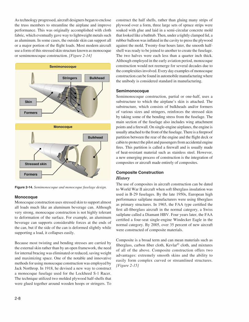
Figure 2-14. Semimonocoque and monocoque fuselage design.
As technology progressed, aircraft designers began to enclose
the truss members to streamline the airplane and improve
performance. This was originally accomplished with cloth
fabric, which eventually gave way to lightweight metals such
as aluminum. In some cases, the outside skin can support all
or a major portion of the flight loads. Most modern aircraft
use a form of this stressed skin structure known as monocoque
or semimonocoque construction. [Figure 2-14]
Monocoque
Monocoque construction uses stressed skin to support almost
all loads much like an aluminum beverage can. Although
very strong, monocoque construction is not highly tolerant
to deformation of the surface. For example, an aluminum
beverage can supports considerable forces at the ends of
the can, but if the side of the can is deformed slightly while
supporting a load, it collapses easily.
Because most twisting and bending stresses are carried by
the external skin rather than by an open framework, the need
for internal bracing was eliminated or reduced, saving weight
and maximizing space. One of the notable and innovative
methods for using monocoque construction was employed by
Jack Northrop. In 1918, he devised a new way to construct
a monocoque fuselage used for the Lockheed S-1 Racer.
The technique utilized two molded plywood half-shells that
were glued together around wooden hoops or stringers. To
construct the half shells, rather than gluing many strips of
plywood over a form, three large sets of spruce strips were
soaked with glue and laid in a semi-circular concrete mold
that looked like a bathtub. Then, under a tightly clamped lid, a
rubber balloon was inflated in the cavity to press the plywood
against the mold. Twenty-four hours later, the smooth half-
shell was ready to be joined to another to create the fuselage.
The two halves were each less than a quarter inch thick.
Although employed in the early aviation period, monocoque
construction would not reemerge for several decades due to
the complexities involved. Every day examples of monocoque
construction can be found in automobile manufacturing where
the unibody is considered standard in manufacturing.
Semimonocoque
Semimonocoque construction, partial or one-half, uses a
substructure to which the airplane’s skin is attached. The
substructure, which consists of bulkheads and/or formers
of various sizes and stringers, reinforces the stressed skin
by taking some of the bending stress from the fuselage. The
main section of the fuselage also includes wing attachment
points and a firewall. On single-engine airplanes, the engine is
usually attached to the front of the fuselage. There is a fireproof
partition between the rear of the engine and the flight deck or
cabin to protect the pilot and passengers from accidental engine
fires. This partition is called a firewall and is usually made
of heat-resistant material such as stainless steel. However,
a new emerging process of construction is the integration of
composites or aircraft made entirely of composites.
Composite Construction
History
The use of composites in aircraft construction can be dated
to World War II aircraft when soft fiberglass insulation was
used in B-29 fuselages. By the late 1950s, European high
performance sailplane manufacturers were using fiberglass
as primary structures. In 1965, the FAA type certified the
first all-fiberglass aircraft in the normal category, a Swiss
sailplane called a Diamant HBV. Four years later, the FAA
certified a four-seat single-engine Windecker Eagle in the
normal category. By 2005, over 35 percent of new aircraft
were constructed of composite materials.
Composite is a broad term and can mean materials such as
fiberglass, carbon fiber cloth, Kevlar© cloth, and mixtures
of all of the above. Composite construction offers two
advantages: extremely smooth skins and the ability to
easily form complex curved or streamlined structures.
[Figure 2-15]
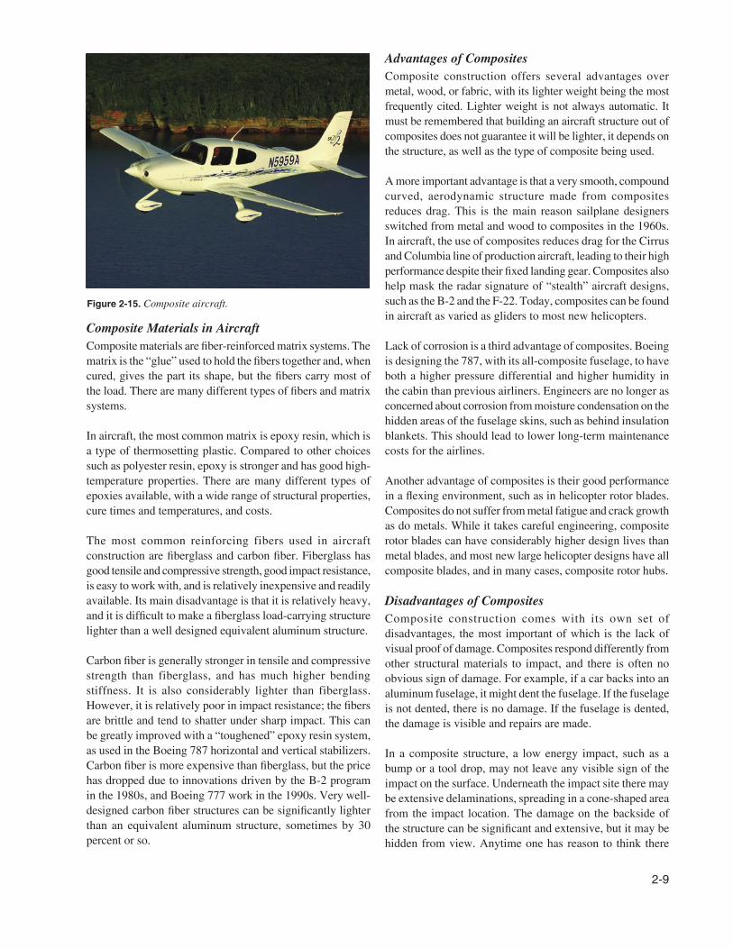
2-9
Figure 2-15. Composite aircraft.
Advantages of Composites
Composite construction offers several advantages over
metal, wood, or fabric, with its lighter weight being the most
frequently cited. Lighter weight is not always automatic. It
must be remembered that building an aircraft structure out of
composites does not guarantee it will be lighter, it depends on
the structure, as well as the type of composite being used.
A more important advantage is that a very smooth, compound
curved, aerodynamic structure made from composites
reduces drag. This is the main reason sailplane designers
switched from metal and wood to composites in the 1960s.
In aircraft, the use of composites reduces drag for the Cirrus
and Columbia line of production aircraft, leading to their high
performance despite their fixed landing gear. Composites also
help mask the radar signature of “stealth” aircraft designs,
such as the B-2 and the F-22. Today, composites can be found
in aircraft as varied as gliders to most new helicopters.
Lack of corrosion is a third advantage of composites. Boeing
is designing the 787, with its all-composite fuselage, to have
both a higher pressure differential and higher humidity in
the cabin than previous airliners. Engineers are no longer as
concerned about corrosion from moisture condensation on the
hidden areas of the fuselage skins, such as behind insulation
blankets. This should lead to lower long-term maintenance
costs for the airlines.
Another advantage of composites is their good performance
in a flexing environment, such as in helicopter rotor blades.
Composites do not suffer from metal fatigue and crack growth
as do metals. While it takes careful engineering, composite
rotor blades can have considerably higher design lives than
metal blades, and most new large helicopter designs have all
composite blades, and in many cases, composite rotor hubs.
Disadvantages of Composites
Composite construction comes with its own set of
disadvantages, the most important of which is the lack of
visual proof of damage. Composites respond differently from
other structural materials to impact, and there is often no
obvious sign of damage. For example, if a car backs into an
aluminum fuselage, it might dent the fuselage. If the fuselage
is not dented, there is no damage. If the fuselage is dented,
the damage is visible and repairs are made.
In a composite structure, a low energy impact, such as a
bump or a tool drop, may not leave any visible sign of the
impact on the surface. Underneath the impact site there may
be extensive delaminations, spreading in a cone-shaped area
from the impact location. The damage on the backside of
the structure can be significant and extensive, but it may be
hidden from view. Anytime one has reason to think there
Composite Materials in Aircraft
Composite materials are fiber-reinforced matrix systems. The
matrix is the “glue” used to hold the fibers together and, when
cured, gives the part its shape, but the fibers carry most of
the load. There are many different types of fibers and matrix
systems.
In aircraft, the most common matrix is epoxy resin, which is
a type of thermosetting plastic. Compared to other choices
such as polyester resin, epoxy is stronger and has good high-
temperature properties. There are many different types of
epoxies available, with a wide range of structural properties,
cure times and temperatures, and costs.
The most common reinforcing fibers used in aircraft
construction are fiberglass and carbon fiber. Fiberglass has
good tensile and compressive strength, good impact resistance,
is easy to work with, and is relatively inexpensive and readily
available. Its main disadvantage is that it is relatively heavy,
and it is difficult to make a fiberglass load-carrying structure
lighter than a well designed equivalent aluminum structure.
Carbon fiber is generally stronger in tensile and compressive
strength than fiberglass, and has much higher bending
stiffness. It is also considerably lighter than fiberglass.
However, it is relatively poor in impact resistance; the fibers
are brittle and tend to shatter under sharp impact. This can
be greatly improved with a “toughened” epoxy resin system,
as used in the Boeing 787 horizontal and vertical stabilizers.
Carbon fiber is more expensive than fiberglass, but the price
has dropped due to innovations driven by the B-2 program
in the 1980s, and Boeing 777 work in the 1990s. Very well-
designed carbon fiber structures can be significantly lighter
than an equivalent aluminum structure, sometimes by 30
percent or so.
2-10
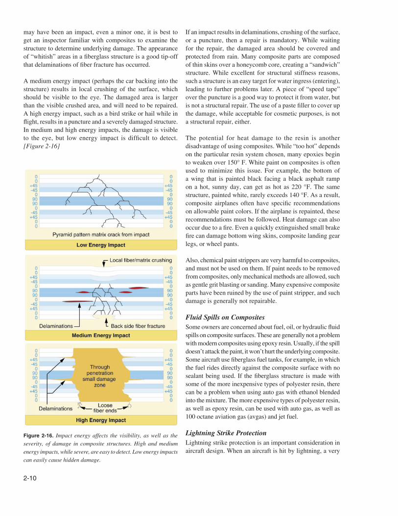
Figure 2-16. Impact energy affects the visibility, as well as the
severity, of damage in composite structures. High and medium
energy impacts, while severe, are easy to detect. Low energy impacts
can easily cause hidden damage.
If an impact results in delaminations, crushing of the surface,
or a puncture, then a repair is mandatory. While waiting
for the repair, the damaged area should be covered and
protected from rain. Many composite parts are composed
of thin skins over a honeycomb core, creating a “sandwich”
structure. While excellent for structural stiffness reasons,
such a structure is an easy target for water ingress (entering),
leading to further problems later. A piece of “speed tape”
over the puncture is a good way to protect it from water, but
is not a structural repair. The use of a paste filler to cover up
the damage, while acceptable for cosmetic purposes, is not
a structural repair, either.
The potential for heat damage to the resin is another
disadvantage of using composites. While “too hot” depends
on the particular resin system chosen, many epoxies begin
to weaken over 150° F. White paint on composites is often
used to minimize this issue. For example, the bottom of
a wing that is painted black facing a black asphalt ramp
on a hot, sunny day, can get as hot as 220 °F. The same
structure, painted white, rarely exceeds 140 °F. As a result,
composite airplanes often have specific recommendations
on allowable paint colors. If the airplane is repainted, these
recommendations must be followed. Heat damage can also
occur due to a fire. Even a quickly extinguished small brake
fire can damage bottom wing skins, composite landing gear
legs, or wheel pants.
Also, chemical paint strippers are very harmful to composites,
and must not be used on them. If paint needs to be removed
from composites, only mechanical methods are allowed, such
as gentle grit blasting or sanding. Many expensive composite
parts have been ruined by the use of paint stripper, and such
damage is generally not repairable.
Fluid Spills on Composites
Some owners are concerned about fuel, oil, or hydraulic fluid
spills on composite surfaces. These are generally not a problem
with modern composites using epoxy resin. Usually, if the spill
doesn’t attack the paint, it won’t hurt the underlying composite.
Some aircraft use fiberglass fuel tanks, for example, in which
the fuel rides directly against the composite surface with no
sealant being used. If the fiberglass structure is made with
some of the more inexpensive types of polyester resin, there
can be a problem when using auto gas with ethanol blended
into the mixture. The more expensive types of polyester resin,
as well as epoxy resin, can be used with auto gas, as well as
100 octane aviation gas (avgas) and jet fuel.
Lightning Strike Protection
Lightning strike protection is an important consideration in
aircraft design. When an aircraft is hit by lightning, a very
may have been an impact, even a minor one, it is best to
get an inspector familiar with composites to examine the
structure to determine underlying damage. The appearance
of “whitish” areas in a fiberglass structure is a good tip-off
that delaminations of fiber fracture has occurred.
A medium energy impact (perhaps the car backing into the
structure) results in local crushing of the surface, which
should be visible to the eye. The damaged area is larger
than the visible crushed area, and will need to be repaired.
A high energy impact, such as a bird strike or hail while in
flight, results in a puncture and a severely damaged structure.
In medium and high energy impacts, the damage is visible
to the eye, but low energy impact is difficult to detect.
[Figure 2-16]
2-11
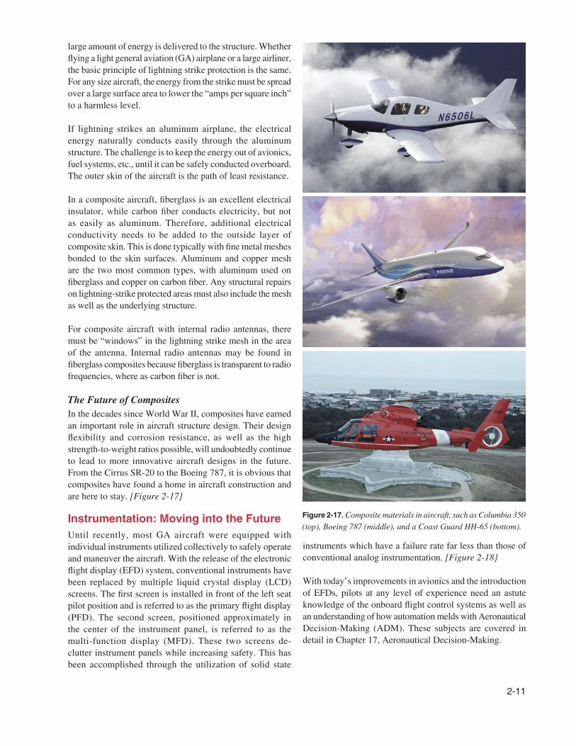
Figure 2-17. Composite materials in aircraft, such as Columbia 350
(top), Boeing 787 (middle), and a Coast Guard HH-65 (bottom).
large amount of energy is delivered to the structure. Whether
flying a light general aviation (GA) airplane or a large airliner,
the basic principle of lightning strike protection is the same.
For any size aircraft, the energy from the strike must be spread
over a large surface area to lower the “amps per square inch”
to a harmless level.
If lightning strikes an aluminum airplane, the electrical
energy naturally conducts easily through the aluminum
structure. The challenge is to keep the energy out of avionics,
fuel systems, etc., until it can be safely conducted overboard.
The outer skin of the aircraft is the path of least resistance.
In a composite aircraft, fiberglass is an excellent electrical
insulator, while carbon fiber conducts electricity, but not
as easily as aluminum. Therefore, additional electrical
conductivity needs to be added to the outside layer of
composite skin. This is done typically with fine metal meshes
bonded to the skin surfaces. Aluminum and copper mesh
are the two most common types, with aluminum used on
fiberglass and copper on carbon fiber. Any structural repairs
on lightning-strike protected areas must also include the mesh
as well as the underlying structure.
For composite aircraft with internal radio antennas, there
must be “windows” in the lightning strike mesh in the area
of the antenna. Internal radio antennas may be found in
fiberglass composites because fiberglass is transparent to radio
frequencies, where as carbon fiber is not.
The Future of Composites
In the decades since World War II, composites have earned
an important role in aircraft structure design. Their design
flexibility and corrosion resistance, as well as the high
strength-to-weight ratios possible, will undoubtedly continue
to lead to more innovative aircraft designs in the future.
From the Cirrus SR-20 to the Boeing 787, it is obvious that
composites have found a home in aircraft construction and
are here to stay. [Figure 2-17]
Instrumentation: Moving into the Future
Until recently, most GA aircraft were equipped with
individual instruments utilized collectively to safely operate
and maneuver the aircraft. With the release of the electronic
flight display (EFD) system, conventional instruments have
been replaced by multiple liquid crystal display (LCD)
screens. The first screen is installed in front of the left seat
pilot position and is referred to as the primary flight display
(PFD). The second screen, positioned approximately in
the center of the instrument panel, is referred to as the
multi-function display (MFD). These two screens de-
clutter instrument panels while increasing safety. This has
been accomplished through the utilization of solid state
instruments which have a failure rate far less than those of
conventional analog instrumentation. [Figure 2-18]
With today’s improvements in avionics and the introduction
of EFDs, pilots at any level of experience need an astute
knowledge of the onboard flight control systems as well as
an understanding of how automation melds with Aeronautical
Decision-Making (ADM). These subjects are covered in
detail in Chapter 17, Aeronautical Decision-Making.
2-12
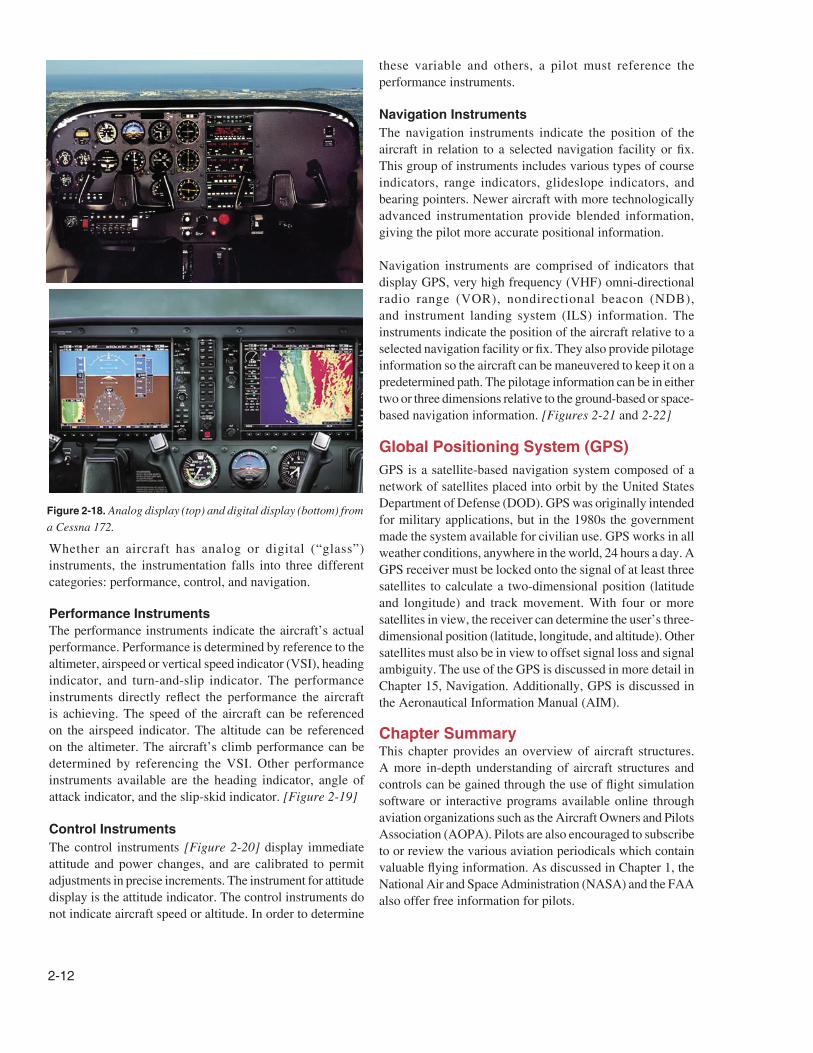
Figure 2-18. Analog display (top) and digital display (bottom) from
a Cessna 172.
Whether an aircraft has analog or digital (“glass”)
instruments, the instrumentation falls into three different
categories: performance, control, and navigation.
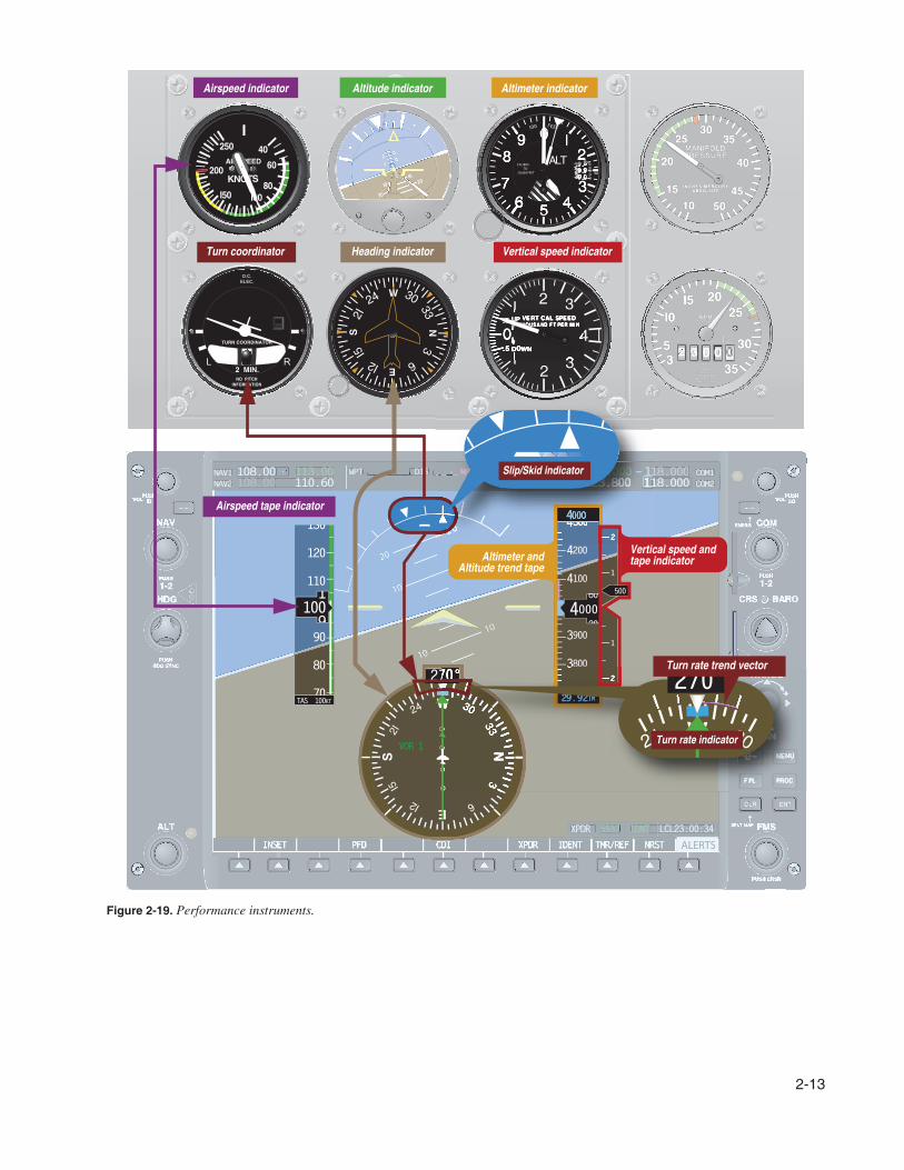
Performance Instruments
The performance instruments indicate the aircraft’s actual
performance. Performance is determined by reference to the
altimeter, airspeed or vertical speed indicator (VSI), heading
indicator, and turn-and-slip indicator. The performance
instruments directly reflect the performance the aircraft
is achieving. The speed of the aircraft can be referenced
on the airspeed indicator. The altitude can be referenced
on the altimeter. The aircraft’s climb performance can be
determined by referencing the VSI. Other performance
instruments available are the heading indicator, angle of
attack indicator, and the slip-skid indicator. [Figure 2-19]
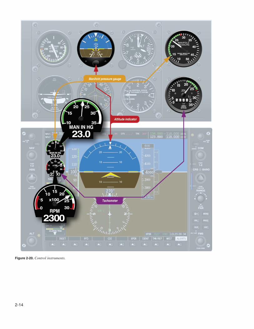
Control Instruments
The control instruments [Figure 2-20] display immediate
attitude and power changes, and are calibrated to permit
adjustments in precise increments. The instrument for attitude
display is the attitude indicator. The control instruments do
not indicate aircraft speed or altitude. In order to determine
these variable and others, a pilot must reference the
performance instruments.
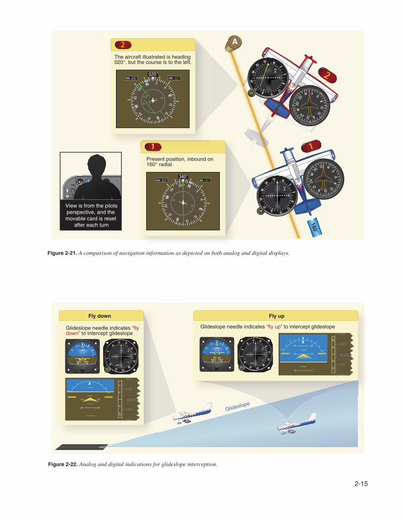
Navigation Instruments
The navigation instruments indicate the position of the
aircraft in relation to a selected navigation facility or fix.
This group of instruments includes various types of course
indicators, range indicators, glideslope indicators, and
bearing pointers. Newer aircraft with more technologically
advanced instrumentation provide blended information,
giving the pilot more accurate positional information.
Navigation instruments are comprised of indicators that
display GPS, very high frequency (VHF) omni-directional
radio range (VOR), nondirectional beacon (NDB),
and instrument landing system (ILS) information. The
instruments indicate the position of the aircraft relative to a
selected navigation facility or fix. They also provide pilotage
information so the aircraft can be maneuvered to keep it on a
predetermined path. The pilotage information can be in either
two or three dimensions relative to the ground-based or space-
based navigation information. [Figures 2-21 and 2-22]
Global Positioning System (GPS)
GPS is a satellite-based navigation system composed of a
network of satellites placed into orbit by the United States
Department of Defense (DOD). GPS was originally intended
for military applications, but in the 1980s the government
made the system available for civilian use. GPS works in all
weather conditions, anywhere in the world, 24 hours a day. A
GPS receiver must be locked onto the signal of at least three
satellites to calculate a two-dimensional position (latitude
and longitude) and track movement. With four or more
satellites in view, the receiver can determine the user’s three-
dimensional position (latitude, longitude, and altitude). Other
satellites must also be in view to offset signal loss and signal
ambiguity. The use of the GPS is discussed in more detail in
Chapter 15, Navigation. Additionally, GPS is discussed in
the Aeronautical Information Manual (AIM).
Chapter SummaryThis chapter provides an overview of aircraft structures.
A more in-depth understanding of aircraft structures and
controls can be gained through the use of flight simulation
software or interactive programs available online through
aviation organizations such as the Aircraft Owners and Pilots
Association (AOPA). Pilots are also encouraged to subscribe
to or review the various aviation periodicals which contain
valuable flying information. As discussed in Chapter 1, the
National Air and Space Administration (NASA) and the FAA
also offer free information for pilots.
2-13
Figure 2-19. Performance instruments.
2-14
Figure 2-20. Control instruments.
2-15
Figure 2-21. A comparison of navigation information as depicted on both analog and digital displays.
Figure 2-22. Analog and digital indications for glideslope interception.

2-16