Embed Size (px)
Citation preview
Chapter 2
Network Design Essentials
Guide to Networking Essentials, Fifth Edition 2
Objectives
• Explain the basics of a network layout
• Describe the standard networking
topologies
• Explain the variations on standard
networking topologies
• Describe the role of hubs and switches in a
network topology
• Construct a basic network layout
Guide to Networking Essentials, Fifth Edition 3
Basics of a Network Layout
• To implement a network, you must first decide
how to best situate the components in a
topology
– Topology refers to the physical layout of its
computers, cables, and other resources, and also to
how those components communicate with each other
• The arrangement of cabling is the physical topology
• The path that data travels between computers on a network
is the logical topology
– Topology has a significant effect on the network’s performance and growth, and equipment decisions
Guide to Networking Essentials, Fifth Edition 4
Understanding Standard Topologies
• Networks are based on three physical topologies
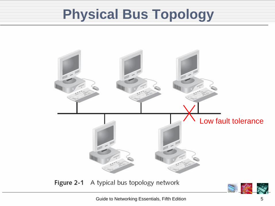
– A bus consists of a series of computers connected
along a single cable segment
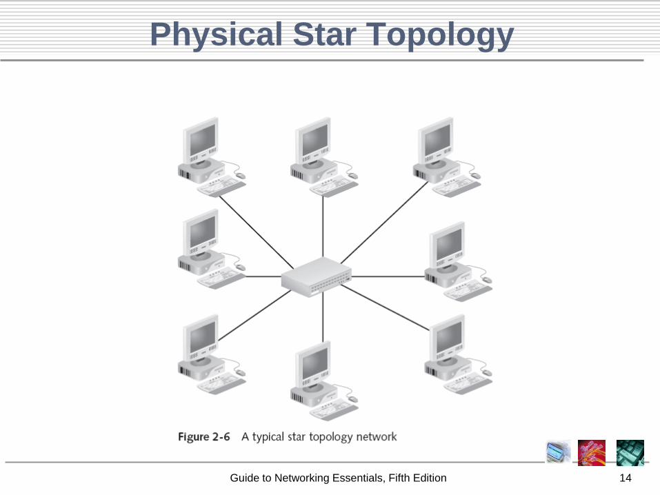
– Computers connected via a central concentration point
(hub) are arranged in a star topology
– Computers connected to form a loop create a ring
• Physical topologies describe cable arrangement
– How the data travels along those cables might
represent a different logical topology
• The logical topologies that dominate LANs include bus,
ring, and switching, all of which are usually implemented
as a physical star
Guide to Networking Essentials, Fifth Edition 5
Physical Bus Topology
Low fault tolerance
Guide to Networking Essentials, Fifth Edition 6
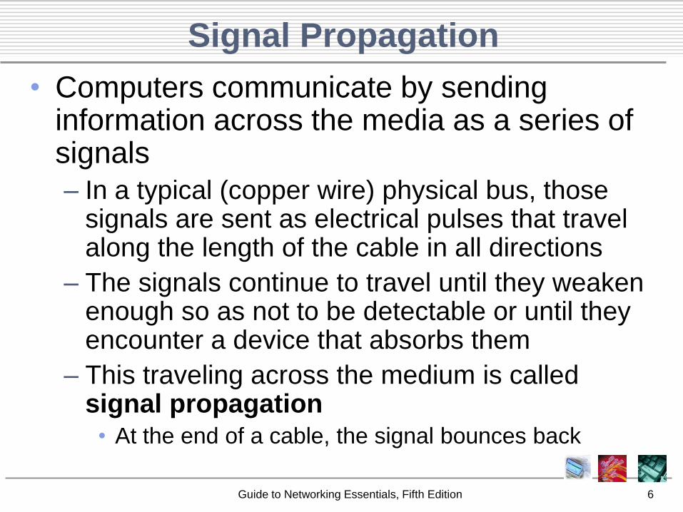
Signal Propagation
• Computers communicate by sending information across the media as a series of signals
– In a typical (copper wire) physical bus, those signals are sent as electrical pulses that travel along the length of the cable in all directions
– The signals continue to travel until they weaken enough so as not to be detectable or until they encounter a device that absorbs them
– This traveling across the medium is called signal propagation
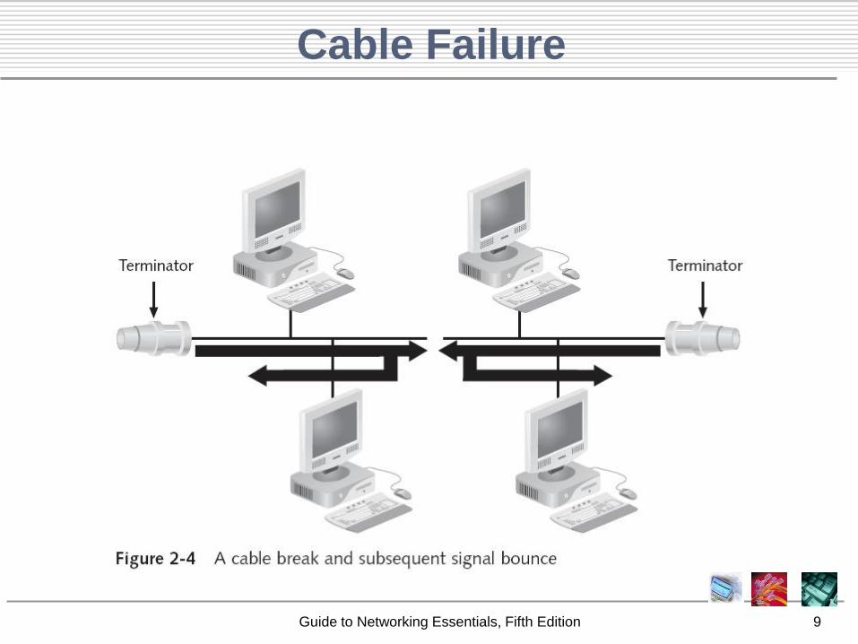
• At the end of a cable, the signal bounces back
Guide to Networking Essentials, Fifth Edition 7
Signal Bounce
Guide to Networking Essentials, Fifth Edition 8
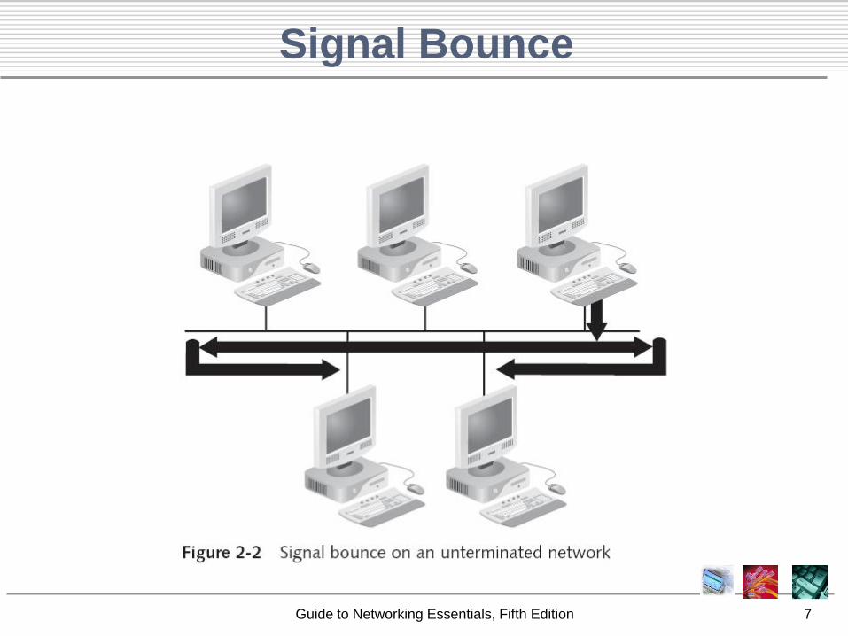
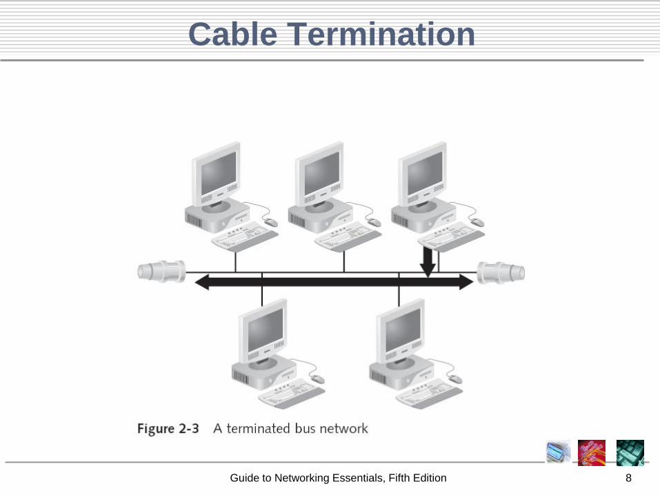
Cable Termination
Guide to Networking Essentials, Fifth Edition 9
Cable Failure
Guide to Networking Essentials, Fifth Edition 10
Logical Bus Topology
• Logical topologies describe the path that data
travels from computer to computer
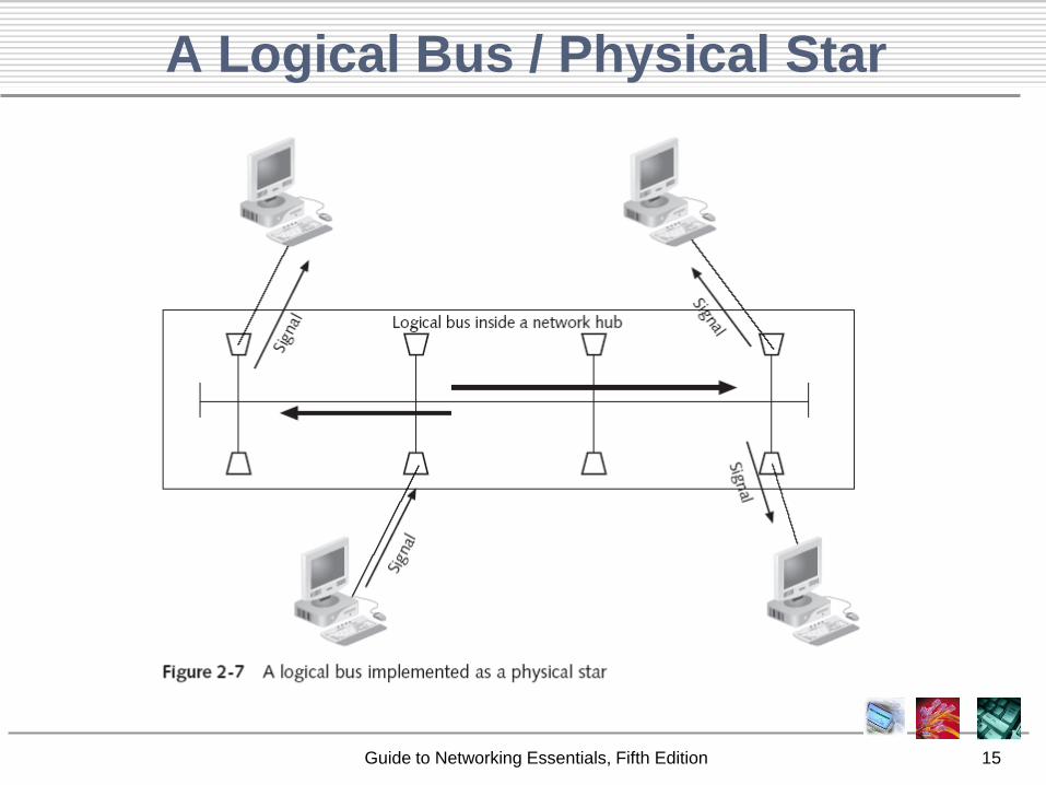
• A physical bus topology is almost always
implemented as a logical bus as well
– Technology has moved past the physical bus, but a
logical bus topology is still in use on some physical
topologies, in particular a star
• All computers communicate in the same way
– They address data to one or more computers and then
transmit that data across the cable in the form of
electronic signals
Guide to Networking Essentials, Fifth Edition 11
Sending the Signal
• When a computer has data to send, it addresses
that data, breaks it into manageable chunks, and
sends it across the network as electronic signals
– All computers on a logical bus receive them
• Only the destination accepts the data
• All users must share the available amount of transmission time
– Thus, network performance is reduced
• A bus topology is a passive topology
– In an active topology network, computers and other
devices regenerate signals and are responsible for
moving data through the network
Guide to Networking Essentials, Fifth Edition 12
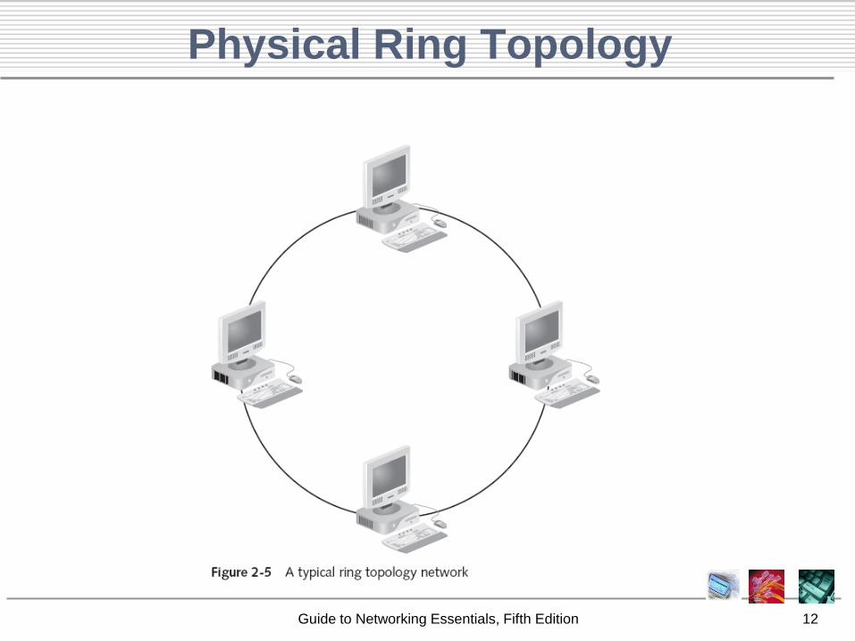
Physical Ring Topology
Guide to Networking Essentials, Fifth Edition 13
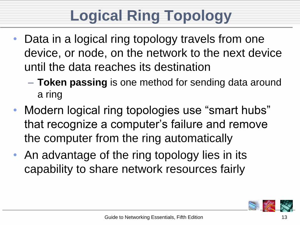
Logical Ring Topology
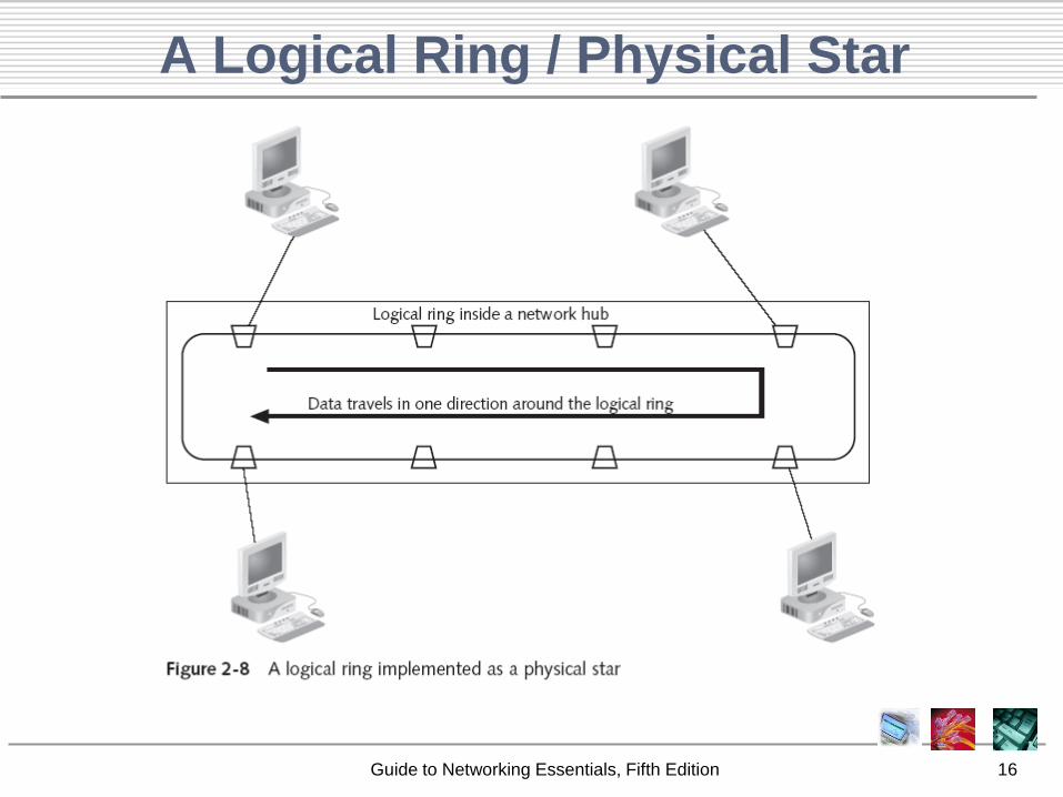
• Data in a logical ring topology travels from one
device, or node, on the network to the next device
until the data reaches its destination
– Token passing is one method for sending data around
a ring
• Modern logical ring topologies use ―smart hubs‖
that recognize a computer’s failure and remove
the computer from the ring automatically
• An advantage of the ring topology lies in its
capability to share network resources fairly
Guide to Networking Essentials, Fifth Edition 14
Physical Star Topology
Guide to Networking Essentials, Fifth Edition 15
A Logical Bus / Physical Star
Guide to Networking Essentials, Fifth Edition 16
A Logical Ring / Physical Star
Guide to Networking Essentials, Fifth Edition 17
Switching Implemented as a Physical Star
• Switching is neither a bus nor a ring logically, but is always implemented as a physical star– A switch takes a signal coming from a device connected
and builds a circuit on the fly to forward the signal to the intended destination computer
– Superior to other logical topologies because, unlike bus and ring, multiple computers can communicate simultaneously without affecting each other
– Dominant method used in almost every LAN design
Guide to Networking Essentials, Fifth Edition 18
Wireless Topologies
• Wireless networking has a logical and
physical topology
– Ad hoc topology: two computers can
communicate directly with one another;
sometimes called a peer-to-peer topology
– Infrastructure mode: Use a central device,
called an access point (AP), to control
communications
• Star physical topology because all the signals travel
through one central device
• Logical bus topology
Guide to Networking Essentials, Fifth Edition 19
Variations of Physical Topologies
• The major physical topologies have three
typical variations or combinations
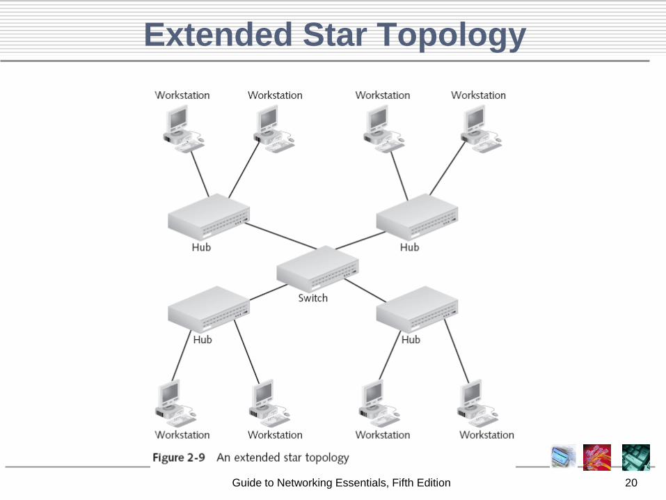
– Extended star
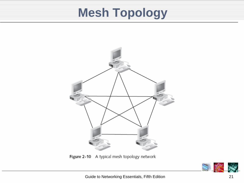
– Mesh
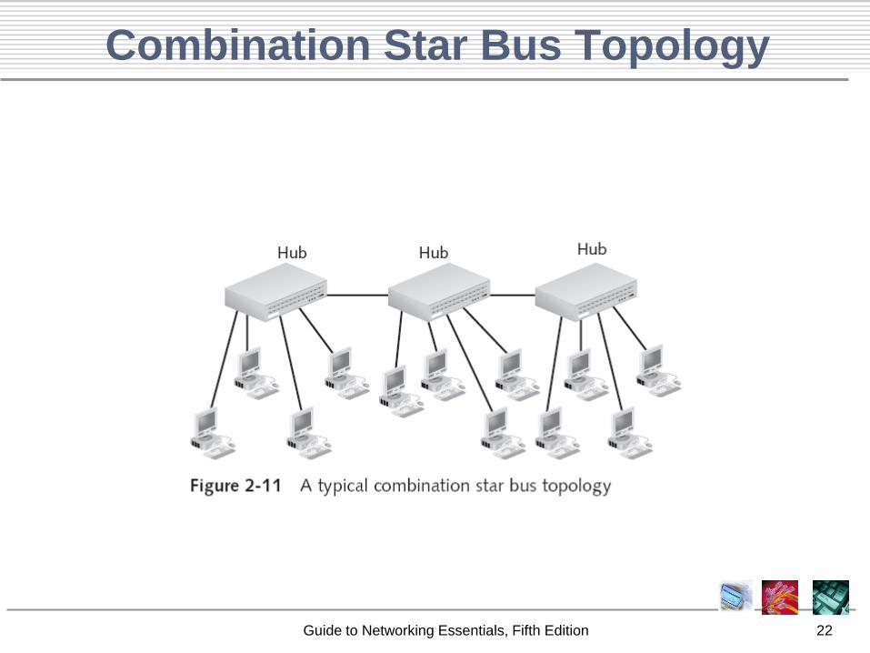
– Combination star and bus
• These combinations can be used to get the
most from any network
Guide to Networking Essentials, Fifth Edition 20
Extended Star Topology
Guide to Networking Essentials, Fifth Edition 21
Mesh Topology
Guide to Networking Essentials, Fifth Edition 22
Combination Star Bus Topology
Guide to Networking Essentials, Fifth Edition 23
Hubs and Switches
• Both hubs and switches can act as the
center of a star topology
• Basic operation was discussed briefly; this
section expands on them
Guide to Networking Essentials, Fifth Edition 24
Hubs
• In everyday use, a hub is ―the center of
activity‖
– This definition is appropriate in network usage
also
• In network usage, there are a number of
variations on this central theme
– Active hub
– Passive hub
– Repeating hub (just a type of active hub)
– Switching hub
Guide to Networking Essentials, Fifth Edition 25
Active Hubs
• Most common type of hub today
• Regenerate, or repeat, the signals
– Require electrical power to run
• Generally, have many ports—eight or more
• Also called multiport repeaters or repeating hubs
1. Takes a signal coming in on one port
2. Cleans the signal (e.g., by filtering out noise)
3. Strengthens the signal
4. Sends the regenerated signal out to all other ports
• Drawback: require sharing the cable bandwidth
among all connected stations
Guide to Networking Essentials, Fifth Edition 26
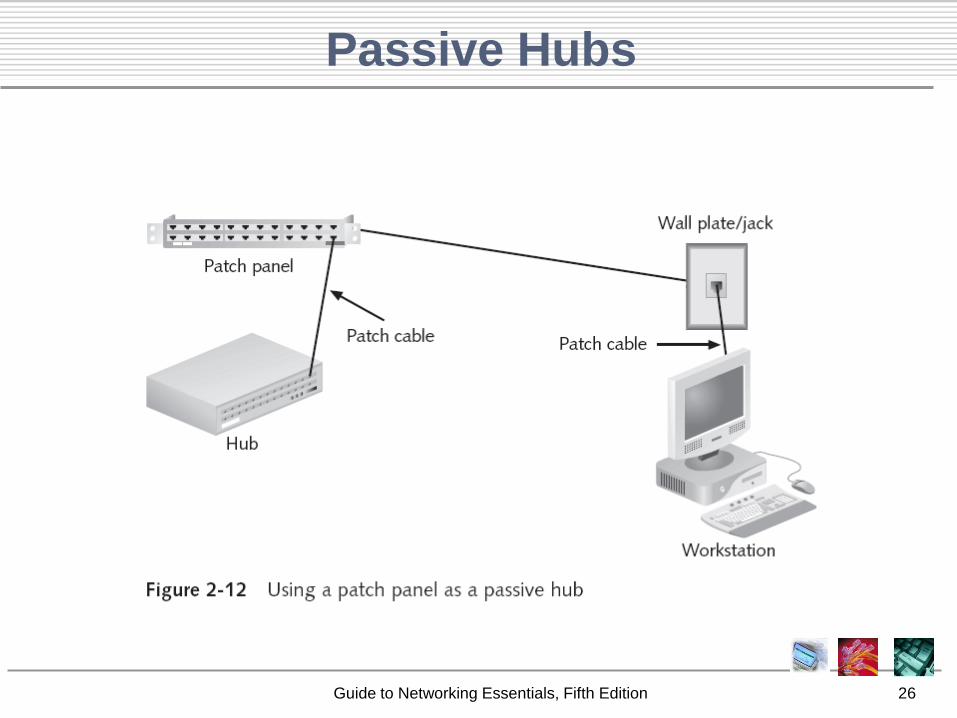
Passive Hubs
Guide to Networking Essentials, Fifth Edition 27
Switches
• Central connecting point in a star topology network
• Does more than simply regenerate signals
• Looks just like a hub, with several ports for
connecting workstations in a star topology
• Determines to which port the destination device is
connected and forwards the message to that port
– This capability allows a switch to handle several
conversations at one time, thereby providing the full
network bandwidth to each device rather than requiring
bandwidth sharing
Guide to Networking Essentials, Fifth Edition 28
Constructing a Network Layout
• The first step in any network design is to
evaluate the underlying requirements
– First determine how the network will be used,
which often decides the topology you use
– Decide the types of devices for interconnecting
computers and sites
– Finally, the type and usage level of network
resources dictates how many servers you need
and where to place servers
Guide to Networking Essentials, Fifth Edition 29
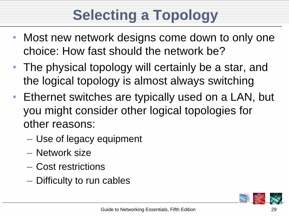
Selecting a Topology
• Most new network designs come down to only one
choice: How fast should the network be?
• The physical topology will certainly be a star, and
the logical topology is almost always switching
• Ethernet switches are typically used on a LAN, but
you might consider other logical topologies for
other reasons:
– Use of legacy equipment
– Network size
– Cost restrictions
– Difficulty to run cables
Guide to Networking Essentials, Fifth Edition 30
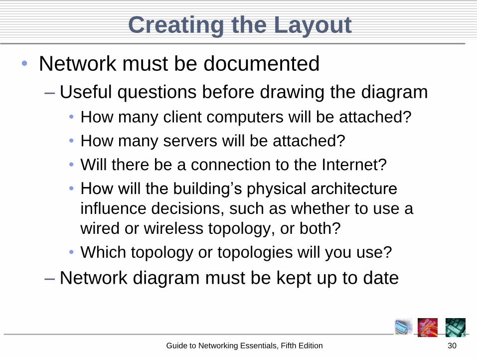
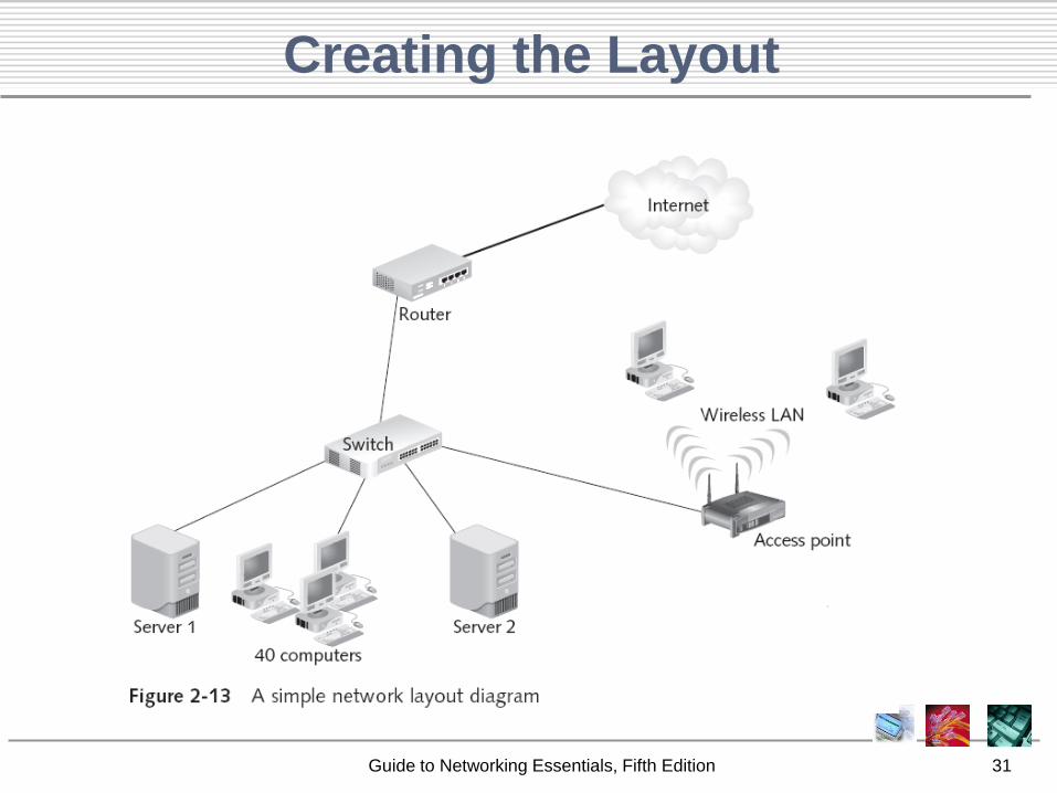
Creating the Layout
• Network must be documented
– Useful questions before drawing the diagram
• How many client computers will be attached?
• How many servers will be attached?
• Will there be a connection to the Internet?
• How will the building’s physical architecture
influence decisions, such as whether to use a
wired or wireless topology, or both?
• Which topology or topologies will you use?
– Network diagram must be kept up to date
Guide to Networking Essentials, Fifth Edition 31
Creating the Layout
Guide to Networking Essentials, Fifth Edition 32
Summary
• Basic physical topologies: bus, star, or ring
– Physical bus: easy to install but outdated• The logical bus topology is still used, but is almost always
implemented as a physical star
– Physical ring: connects devices in such a way that the cabling starts and ends with the same computer
• Rarely used (except in FDDI)
• Logical ring topology typically uses token passing to send data around ring; normally implemented as a star
– Physical star: centralized management and higher degree of fault tolerance
• Topology of choice in today’s networks
Guide to Networking Essentials, Fifth Edition 33
Summary
• For wireless networks: ad hoc or infrastructure mode
• Variations on major topologies
– Extended star (most widely used)
– Mesh (most fault tolerant)
– Combination star and bus
• Hub: central point of concentration for a star network
– Can be active (if it regenerates the signals) or passive
• Switch: provides better performance than a hub
– Device of choice in corporate star topology networks
• Network layout should be consistent and maintained accurately as the network changes