Embed Size (px)
Citation preview
Mini-Circuits Portable Test Equipment Programming Manual Page 2-1 Chapter 2 - RF Switch Matrices 30-Jul-13 (A0)
Chapter 2 - RF Switch Matrices
Chapter 2 - RF Switch Matrices .................................................................... 2-1
2.1 - Operating in a Windows Environment ................................................................ 2-3 2.1.1 - Referencing the DLL Library .............................................................................................. 2-3 2.1.2 - Summary of DLL Functions ............................................................................................... 2-4 2.1.3 - Detailed Description of DLL Functions.............................................................................. 2-5
2.1.3 (a) - Connect to Switch Matrix ......................................................................................... 2-5 2.1.3 (b) - Connect to Switch Matrix by Address ...................................................................... 2-6 2.1.3 (c) - Disconnect from Switch Matrix ................................................................................ 2-7 2.1.3 (d) - Get Switch Status ..................................................................................................... 2-8 2.1.3 (e) - Read Model Name of Switch Matrix ...................................................................... 2-12 2.1.3 (f) - Read Serial Number of Switch Matrix ..................................................................... 2-13 2.1.3 (g) - Set Individual Switch .............................................................................................. 2-14 2.1.3 (h) - Set All Switches ...................................................................................................... 2-16 2.1.3 (i) - Set SP4T Switch ....................................................................................................... 2-18 2.1.3 (j) - Set Address of Switch Matrix .................................................................................. 2-20 2.1.3 (k) - Get Address of Switch Matrix ................................................................................ 2-21 2.1.3 (l) - Get List of Connected Serial Numbers .................................................................... 2-22 2.1.3 (m) - Get List of Available Addresses ............................................................................. 2-23 2.1.3 (n) - Get Temperature of Switch Matrix ........................................................................ 2-24 2.1.3 (o) - Get Heat Alarm ...................................................................................................... 2-25 2.1.3 (p) - Get 24V DC Supply Status ...................................................................................... 2-26 2.1.3 (q) - Get Fan Status ........................................................................................................ 2-28 2.1.3 (r) - Get Software Connection Status ............................................................................ 2-30 2.1.3 (s) - Get USB Connection Status .................................................................................... 2-31 2.1.3 (t) - Check Connection (Antiquated).............................................................................. 2-32 2.1.3 (u) - Get USB Device Name ............................................................................................ 2-33 2.1.3 (v) - Get Firmware Version ............................................................................................ 2-34
2.2 - Operating in a Linux Environment ..................................................................... 2-35 2.2.1 - Summary of Commands ................................................................................................. 2-35 2.2.2 - Detailed Description of Commands ................................................................................ 2-36
2.2.2 (a) - Get Device Model Name ........................................................................................ 2-36 2.2.2 (b) - Get Device Serial Number ...................................................................................... 2-38 2.2.2 (c) - Set Single SPDT Switch ........................................................................................... 2-39 2.2.2 (d) - Set All SPDT Switches ............................................................................................. 2-40 2.2.2 (e) - Set SP4T Switch State ............................................................................................. 2-42 2.2.2 (f) - Get States of all Switches........................................................................................ 2-43 2.2.2 (g) - Get Internal Temperature ...................................................................................... 2-45 2.2.2 (h) - Get 24V DC Power Status ....................................................................................... 2-47 2.2.2 (i) - Get Heat Alarm ....................................................................................................... 2-48 2.2.2 (j) - Get Fan Status ......................................................................................................... 2-49
2.3 - Ethernet Control over IP Networks ................................................................... 2-50 2.3.1 - Configuring Ethernet Settings ........................................................................................ 2-50 2.3.2 - Ethernet Communication ............................................................................................... 2-51
2.3.2 (a) - Setting Switch Properties ....................................................................................... 2-51 2.3.2 (b) - Querying Switch Properties ................................................................................... 2-52
2.3.3 - Summary of Ethernet Commands/Queries .................................................................... 2-53
Mini-Circuits Portable Test Equipment Programming Manual Page 2-2 Chapter 2 - RF Switch Matrices 30-Jul-13 (A0)
2.3.4 - Detailed Description of Ethernet Commands/Queries .................................................. 2-54 2.3.4 (a) - Set Single SPDT Switch ........................................................................................... 2-54 2.3.4 (b) - Set All SPDT Switches ............................................................................................. 2-55 2.3.4 (c) - Get States of All SPDT Switches ............................................................................. 2-57 2.3.4 (d) - Get Model Name .................................................................................................... 2-58 2.3.4 (e) - Get Serial Number .................................................................................................. 2-59 2.3.4 (f) - Get Internal Temperature ....................................................................................... 2-60 2.3.4 (g) - Get DC Power Status .............................................................................................. 2-61 2.3.4 (h) - Get Heat Alarm ...................................................................................................... 2-62 2.3.4 (i) - Get Fan Status ......................................................................................................... 2-63
Mini-Circuits Portable Test Equipment Programming Manual Page 2-3 Chapter 2 - RF Switch Matrices 30-Jul-13 (A0)
2.1 - Operating in a Windows Environment
2.1.1 - Referencing the DLL Library
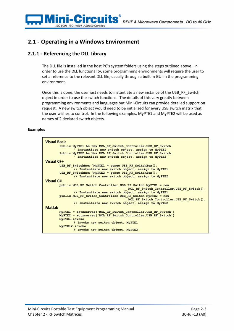
The DLL file is installed in the host PC’s system folders using the steps outlined above. In order to use the DLL functionality, some programming environments will require the user to set a reference to the relevant DLL file, usually through a built in GUI in the programming environment. Once this is done, the user just needs to instantiate a new instance of the USB_RF_Switch object in order to use the switch functions. The details of this vary greatly between programming environments and languages but Mini-Circuits can provide detailed support on request. A new switch object would need to be initialized for every USB switch matrix that the user wishes to control. In the following examples, MyPTE1 and MyPTE2 will be used as names of 2 declared switch objects.
Examples
Visual Basic Public MyPTE1 As New MCL_RF_Switch_Controller.USB_RF_Switch
' Instantiate new switch object, assign to MyPTE1
Public MyPTE2 As New MCL_RF_Switch_Controller.USB_RF_Switch
' Instantiate new switch object, assign to MyPTE2
Visual C++ USB_RF_SwitchBox ^MyPTE1 = gcnew USB_RF_SwitchBox();
// Instantiate new switch object, assign to MyPTE1
USB_RF_SwitchBox ^MyPTE2 = gcnew USB_RF_SwitchBox();
// Instantiate new switch object, assign to MyPTE2 Visual C#
public MCL_RF_Switch_Controller.USB_RF_Switch MyPTE1 = new
_ MCL_RF_Switch_Controller.USB_RF_Switch();
// Instantiate new switch object, assign to MyPTE1
public MCL_RF_Switch_Controller.USB_RF_Switch MyPTE2 = new
_ MCL_RF_Switch_Controller.USB_RF_Switch();
// Instantiate new switch object, assign to MyPTE2
Matlab MyPTE1 = actxserver('MCL_RF_Switch_Controller.USB_RF_Switch')
MyPTE2 = actxserver('MCL_RF_Switch_Controller.USB_RF_Switch')
MyPTE1.invoke
% Invoke new switch object, MyPTE1
MyPTE12.invoke
% Invoke new switch object, MyPTE2

Mini-Circuits Portable Test Equipment Programming Manual Page 2-4 Chapter 2 - RF Switch Matrices 30-Jul-13 (A0)
2.1.2 - Summary of DLL Functions
The following functions are defined in both of the DLL files. Please see the following sections for a full description of their structure and implementation.
a) Short Connect (Optional String SN) b) Short ConnectByAddress (Optional Short Address) c) Void Disconnect () d) Short GetSwitchesStatus (Short StatusRet) e) Short Read_ModelName (String ModelName) f) Short Read_SN (String SN) g) Short Set_Switch (String SwitchName, Short Val) h) Short Set_SwitchesPort (Byte Val) i) Short Set_SP4T_COM_To (Byte Port) j) Short Set_Address (Short Address) k) Short Get_Address () l) Short Get_Available_SN_List (String SN_List) m) Short Get_Available_Address_List (String Add_List) n) Float GetDeviceTemperature (Short TSensor) o) Short GetHeatAlarm () p) Short Get_24V_Indicator () q) Short Get_FAN_Indicator () r) Short GetConnectionStatus () s) Short GetUSBConnectionStatus () t) Short Check_Connection () u) String GetUSBDeviceName () v) Short GetFirmware ()
Mini-Circuits Portable Test Equipment Programming Manual Page 2-5 Chapter 2 - RF Switch Matrices 30-Jul-13 (A0)
2.1.3 - Detailed Description of DLL Functions
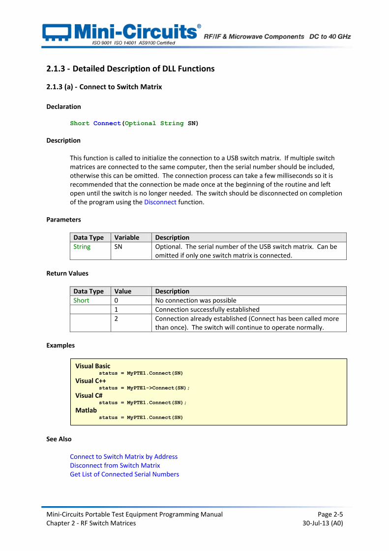
2.1.3 (a) - Connect to Switch Matrix
Declaration Short Connect(Optional String SN)
Description
This function is called to initialize the connection to a USB switch matrix. If multiple switch matrices are connected to the same computer, then the serial number should be included, otherwise this can be omitted. The connection process can take a few milliseconds so it is recommended that the connection be made once at the beginning of the routine and left open until the switch is no longer needed. The switch should be disconnected on completion of the program using the Disconnect function.
Parameters
Data Type Variable Description
String SN Optional. The serial number of the USB switch matrix. Can be omitted if only one switch matrix is connected.
Return Values
Data Type Value Description
Short 0 No connection was possible
1 Connection successfully established
2 Connection already established (Connect has been called more than once). The switch will continue to operate normally.
Examples
See Also Connect to Switch Matrix by Address Disconnect from Switch Matrix Get List of Connected Serial Numbers
Visual Basic status = MyPTE1.Connect(SN)
Visual C++ status = MyPTE1->Connect(SN);
Visual C# status = MyPTE1.Connect(SN);
Matlab status = MyPTE1.Connect(SN)
Mini-Circuits Portable Test Equipment Programming Manual Page 2-6 Chapter 2 - RF Switch Matrices 30-Jul-13 (A0)
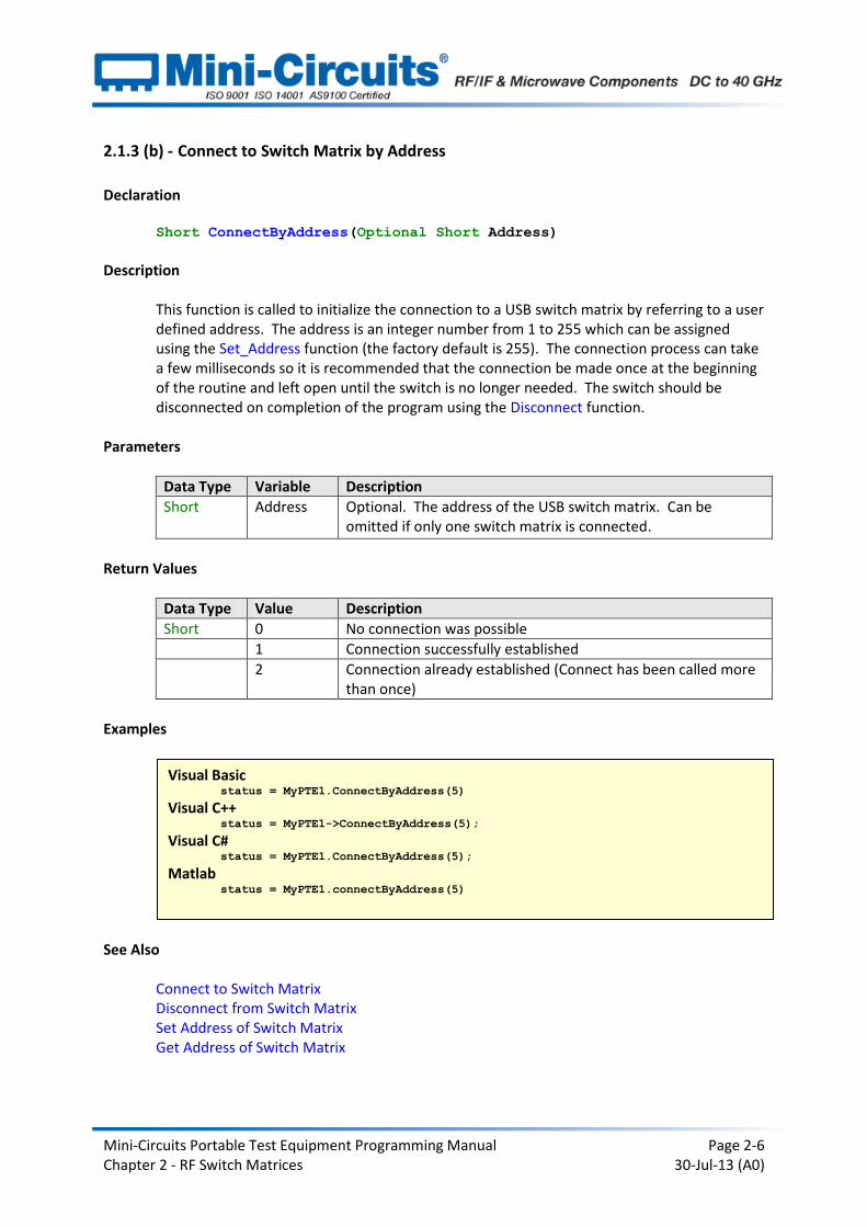
2.1.3 (b) - Connect to Switch Matrix by Address
Declaration Short ConnectByAddress(Optional Short Address)
Description
This function is called to initialize the connection to a USB switch matrix by referring to a user defined address. The address is an integer number from 1 to 255 which can be assigned using the Set_Address function (the factory default is 255). The connection process can take a few milliseconds so it is recommended that the connection be made once at the beginning of the routine and left open until the switch is no longer needed. The switch should be disconnected on completion of the program using the Disconnect function.
Parameters
Data Type Variable Description
Short Address Optional. The address of the USB switch matrix. Can be omitted if only one switch matrix is connected.
Return Values
Data Type Value Description
Short 0 No connection was possible
1 Connection successfully established
2 Connection already established (Connect has been called more than once)
Examples
See Also
Connect to Switch Matrix Disconnect from Switch Matrix Set Address of Switch Matrix Get Address of Switch Matrix
Visual Basic status = MyPTE1.ConnectByAddress(5)
Visual C++ status = MyPTE1->ConnectByAddress(5);
Visual C# status = MyPTE1.ConnectByAddress(5);
Matlab status = MyPTE1.connectByAddress(5)

Mini-Circuits Portable Test Equipment Programming Manual Page 2-7 Chapter 2 - RF Switch Matrices 30-Jul-13 (A0)
2.1.3 (c) - Disconnect from Switch Matrix
Declaration Void Disconnect()
Description
This function is called to close the connection to the switch matrix after completion of the switching routine. It is strongly recommended that this function is used prior to ending the program. Failure to do so may result in a connection problem with the device. Should this occur, shut down the program and unplug the switch matrix from the computer, then reconnect the switch matrix before attempting to start again.
Parameters
Data Type Variable Description
None
Return Values
Data Type Value Description
None
Examples
See Also
Connect to Switch Matrix Connect to Switch Matrix by Address
Visual Basic MyPTE1.Disconnect()
Visual C++ MyPTE1->Disconnect();
Visual C# MyPTE1.Disconnect();
Matlab MyPTE1.Disconnect

Mini-Circuits Portable Test Equipment Programming Manual Page 2-8 Chapter 2 - RF Switch Matrices 30-Jul-13 (A0)
2.1.3 (d) - Get Switch Status
Declaration Short GetSwitchesStatus(Short StatusRet)
Description
This function is called to determine the states of all switches in the switch matrix. The user passes an integer variable to the function which is updated with the current status of each switch in the matrix. The indicated status differs between SPDT switch matrices and SP4T switch matrices (see explanations below).
Parameters (USB-xSPDT-A18)
Data Type Variable Description
Short StatusRet Required. A user defined variable that will be updated with the current status. The integer should be interpreted by the user as binary with the LSB representing the state of switch A, the next bit representing the state of switch B (if applicable) and so on. Each bit will be either 0 (COM connected to port 1) or 1 (COM connected to port 2). Any bits representing switches that are not available in the current model will be 0. For example: 1) StatusRet = 12 2) Convert to binary string = 00001100 3) Bits 3 (switch C) and 4 (switch D) = 1, all others = 0 Therefore: Switch A = 0 (COM connected to port 1) Switch B = 0 (COM connected to port 1) Switch C = 1 (COM connected to port 2) Switch D = 1 (COM connected to port 2) All other switches (if applicable) = 0 (COM connected to port 1)
Parameters (USB-1SP4T-A18)
Data Type Variable Description
Short StatusRet Required. An integer variable that will be updated with the current status. The integer represents a binary value, where each bit corresponds to a switch output. The possible values and their meanings are: 0 (binary 00000000), all ports disconnected 1 (binary 00000001), Com connected to port 1 2 (binary 00000010), Com connected to port 2 4 (binary 00000100), Com connected to port 3 8 (binary 00001000), Com connected to port 4
Mini-Circuits Portable Test Equipment Programming Manual Page 2-9 Chapter 2 - RF Switch Matrices 30-Jul-13 (A0)
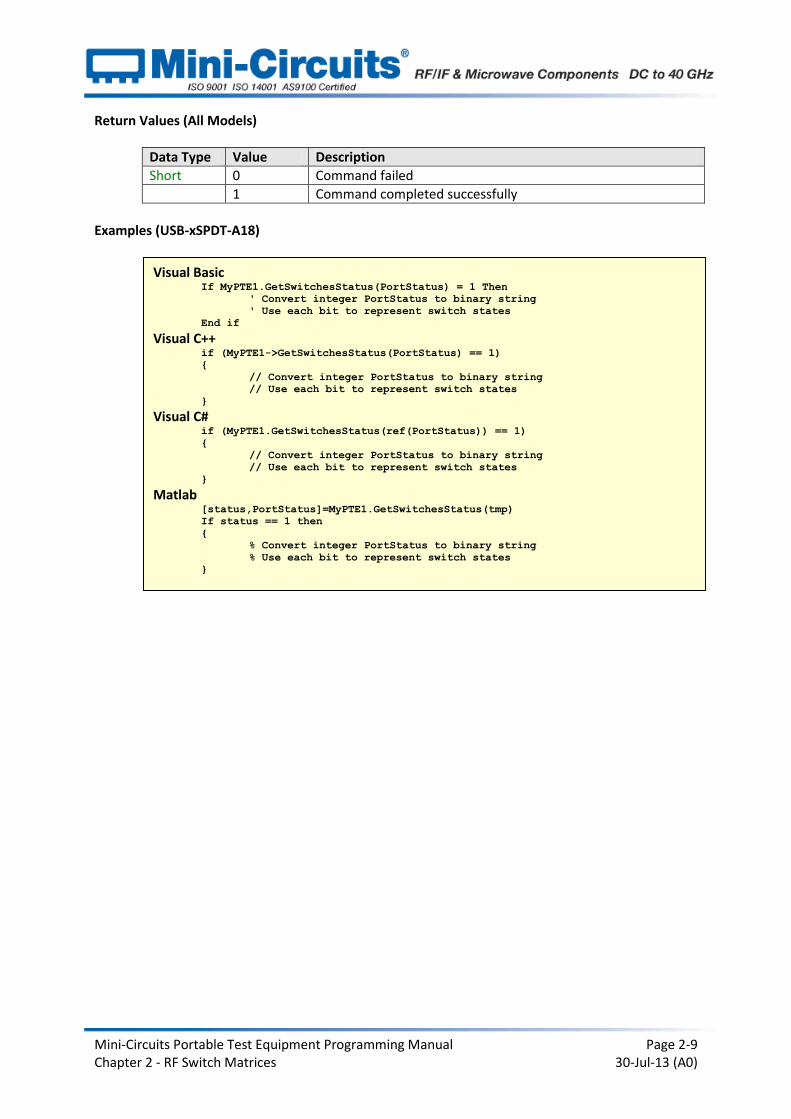
Return Values (All Models)
Data Type Value Description
Short 0 Command failed
1 Command completed successfully
Examples (USB-xSPDT-A18)
Visual Basic If MyPTE1.GetSwitchesStatus(PortStatus) = 1 Then
' Convert integer PortStatus to binary string
' Use each bit to represent switch states
End if Visual C++
if (MyPTE1->GetSwitchesStatus(PortStatus) == 1)
{
// Convert integer PortStatus to binary string
// Use each bit to represent switch states }
Visual C# if (MyPTE1.GetSwitchesStatus(ref(PortStatus)) == 1)
{
// Convert integer PortStatus to binary string
// Use each bit to represent switch states
} Matlab
[status,PortStatus]=MyPTE1.GetSwitchesStatus(tmp)
If status == 1 then
{
% Convert integer PortStatus to binary string
% Use each bit to represent switch states
}
Mini-Circuits Portable Test Equipment Programming Manual Page 2-10 Chapter 2 - RF Switch Matrices 30-Jul-13 (A0)
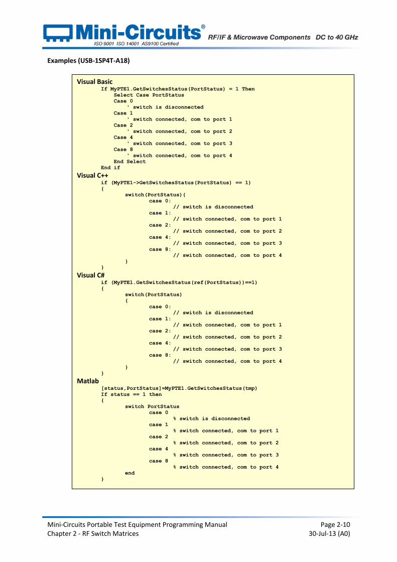
Examples (USB-1SP4T-A18)
Visual Basic If MyPTE1.GetSwitchesStatus(PortStatus) = 1 Then
Select Case PortStatus
Case 0
' switch is disconnected
Case 1
' switch connected, com to port 1
Case 2
' switch connected, com to port 2
Case 4
' switch connected, com to port 3
Case 8
' switch connected, com to port 4
End Select
End if
Visual C++ if (MyPTE1->GetSwitchesStatus(PortStatus) == 1)
{
switch(PortStatus){
case 0:
// switch is disconnected
case 1:
// switch connected, com to port 1
case 2:
// switch connected, com to port 2
case 4:
// switch connected, com to port 3
case 8:
// switch connected, com to port 4
}
} Visual C#
if (MyPTE1.GetSwitchesStatus(ref(PortStatus))==1)
{
switch(PortStatus)
{
case 0:
// switch is disconnected
case 1:
// switch connected, com to port 1
case 2:
// switch connected, com to port 2
case 4:
// switch connected, com to port 3
case 8:
// switch connected, com to port 4
}
} Matlab
[status,PortStatus]=MyPTE1.GetSwitchesStatus(tmp)
If status == 1 then
{
switch PortStatus
case 0
% switch is disconnected
case 1
% switch connected, com to port 1
case 2
% switch connected, com to port 2
case 4
% switch connected, com to port 3
case 8
% switch connected, com to port 4
end
}
Mini-Circuits Portable Test Equipment Programming Manual Page 2-11 Chapter 2 - RF Switch Matrices 30-Jul-13 (A0)
See Also
Set Individual Switch Set All Switches Set SP4T Switch
Mini-Circuits Portable Test Equipment Programming Manual Page 2-12 Chapter 2 - RF Switch Matrices 30-Jul-13 (A0)
2.1.3 (e) - Read Model Name of Switch Matrix
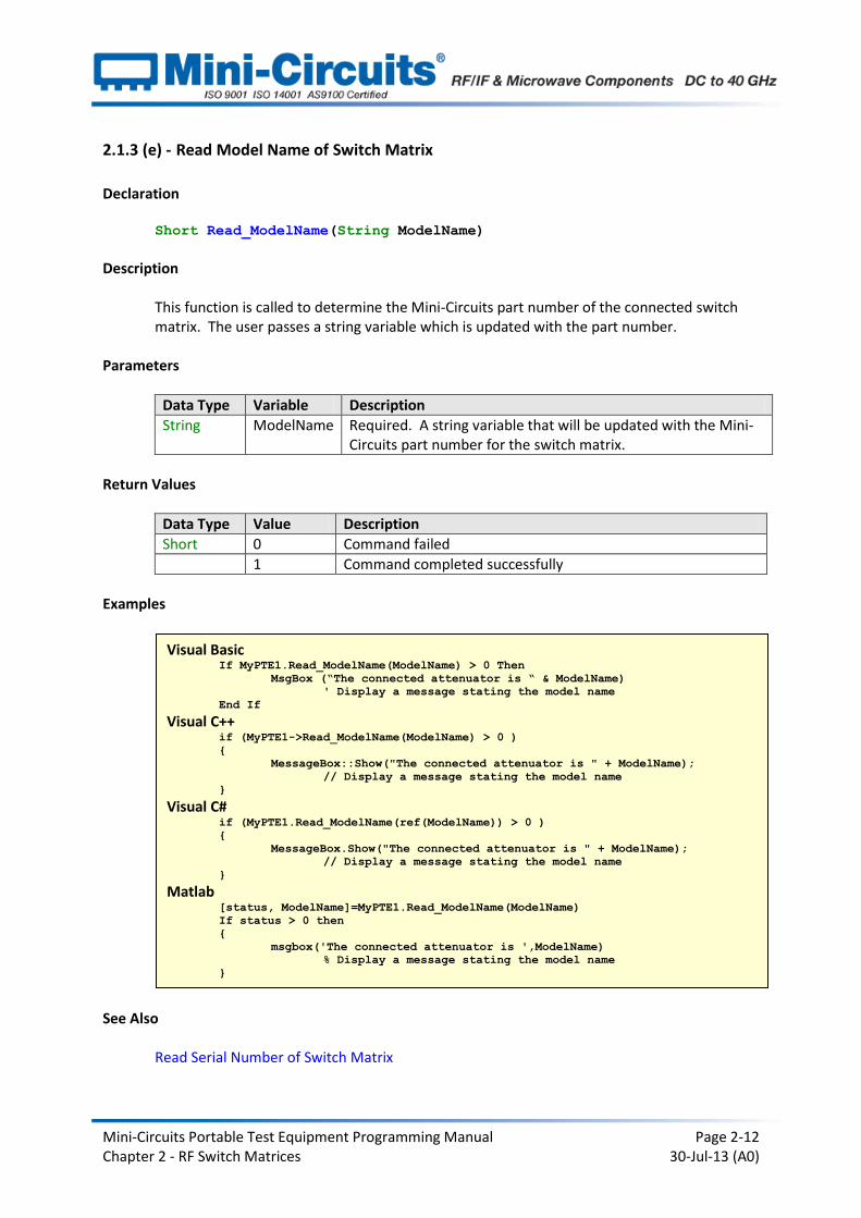
Declaration Short Read_ModelName(String ModelName)
Description
This function is called to determine the Mini-Circuits part number of the connected switch matrix. The user passes a string variable which is updated with the part number.
Parameters
Data Type Variable Description
String ModelName Required. A string variable that will be updated with the Mini-Circuits part number for the switch matrix.
Return Values
Data Type Value Description
Short 0 Command failed
1 Command completed successfully
Examples
See Also Read Serial Number of Switch Matrix
Visual Basic If MyPTE1.Read_ModelName(ModelName) > 0 Then
MsgBox (“The connected attenuator is “ & ModelName)
' Display a message stating the model name
End If Visual C++
if (MyPTE1->Read_ModelName(ModelName) > 0 )
{
MessageBox::Show("The connected attenuator is " + ModelName);
// Display a message stating the model name
} Visual C#
if (MyPTE1.Read_ModelName(ref(ModelName)) > 0 )
{
MessageBox.Show("The connected attenuator is " + ModelName);
// Display a message stating the model name
} Matlab
[status, ModelName]=MyPTE1.Read_ModelName(ModelName)
If status > 0 then
{
msgbox('The connected attenuator is ',ModelName)
% Display a message stating the model name
}
Mini-Circuits Portable Test Equipment Programming Manual Page 2-13 Chapter 2 - RF Switch Matrices 30-Jul-13 (A0)
2.1.3 (f) - Read Serial Number of Switch Matrix
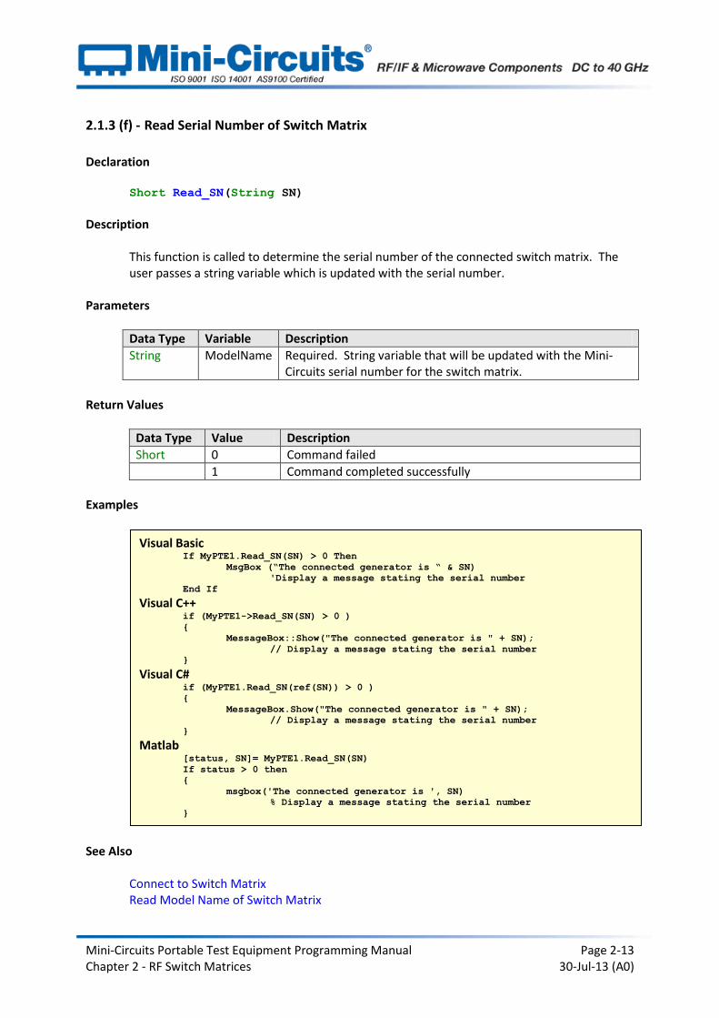
Declaration Short Read_SN(String SN)
Description
This function is called to determine the serial number of the connected switch matrix. The user passes a string variable which is updated with the serial number.
Parameters
Data Type Variable Description
String ModelName Required. String variable that will be updated with the Mini-Circuits serial number for the switch matrix.
Return Values
Data Type Value Description
Short 0 Command failed
1 Command completed successfully
Examples
See Also Connect to Switch Matrix Read Model Name of Switch Matrix
Visual Basic If MyPTE1.Read_SN(SN) > 0 Then
MsgBox (“The connected generator is “ & SN)
'Display a message stating the serial number
End If Visual C++
if (MyPTE1->Read_SN(SN) > 0 )
{
MessageBox::Show("The connected generator is " + SN);
// Display a message stating the serial number
} Visual C#
if (MyPTE1.Read_SN(ref(SN)) > 0 )
{
MessageBox.Show("The connected generator is " + SN);
// Display a message stating the serial number
} Matlab
[status, SN]= MyPTE1.Read_SN(SN)
If status > 0 then
{
msgbox('The connected generator is ', SN)
% Display a message stating the serial number
}
Mini-Circuits Portable Test Equipment Programming Manual Page 2-14 Chapter 2 - RF Switch Matrices 30-Jul-13 (A0)
2.1.3 (g) - Set Individual Switch
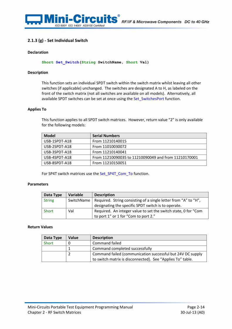
Declaration Short Set_Switch(String SwitchName, Short Val)
Description
This function sets an individual SPDT switch within the switch matrix whilst leaving all other switches (if applicable) unchanged. The switches are designated A to H, as labeled on the front of the switch matrix (not all switches are available on all models). Alternatively, all available SPDT switches can be set at once using the Set_SwitchesPort function.
Applies To
This function applies to all SPDT switch matrices. However, return value “2” is only available for the following models:
Model Serial Numbers
USB-1SPDT-A18 From 11210140015
USB-2SPDT-A18 From 11010030072
USB-3SPDT-A18 From 11210140041
USB-4SPDT-A18 From 11210090035 to 11210090049 and from 11210170001
USB-8SPDT-A18 From 11210150051
For SP4T switch matrices use the Set_SP4T_Com_To function.
Parameters
Data Type Variable Description
String SwitchName Required. String consisting of a single letter from “A” to “H”, designating the specific SPDT switch is to operate.
Short Val Required. An integer value to set the switch state, 0 for “Com to port 1” or 1 for “Com to port 2.”
Return Values
Data Type Value Description
Short 0 Command failed
1 Command completed successfully
2 Command failed (communication successful but 24V DC supply to switch matrix is disconnected). See “Applies To” table.
Mini-Circuits Portable Test Equipment Programming Manual Page 2-15 Chapter 2 - RF Switch Matrices 30-Jul-13 (A0)
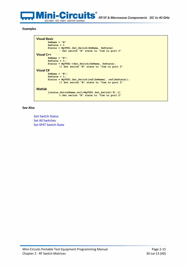
Examples
See Also Get Switch Status Set All Switches Set SP4T Switch State
Visual Basic SwName = "B"
SwState = 1
Status = MyPTE1.Set_Switch(SwName, SwState)
' Set switch "B" state to "Com to port 2"
Visual C++ SwName = "B";
SwState = 1;
Status = MyPTE1->Set_Switch(SwName, SwState);
// Set switch "B" state to "Com to port 2" Visual C#
SwName = "B";
SwState = 1;
Status = MyPTE1.Set_Switch(ref(SwName), ref(SwState));
// Set switch "B" state to "Com to port 2"
Matlab [status,SwitchName,val]=MyPTE1.Set_Switch('B',1)
% Set switch "B" state to “Com to port 2”
Mini-Circuits Portable Test Equipment Programming Manual Page 2-16 Chapter 2 - RF Switch Matrices 30-Jul-13 (A0)
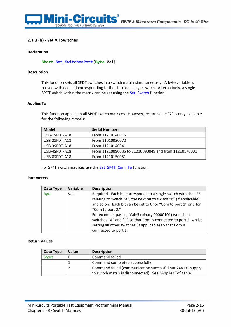
2.1.3 (h) - Set All Switches
Declaration Short Set_SwitchesPort(Byte Val)
Description
This function sets all SPDT switches in a switch matrix simultaneously. A byte variable is passed with each bit corresponding to the state of a single switch. Alternatively, a single SPDT switch within the matrix can be set using the Set_Switch function.
Applies To
This function applies to all SPDT switch matrices. However, return value “2” is only available for the following models:
Model Serial Numbers
USB-1SPDT-A18 From 11210140015
USB-2SPDT-A18 From 11010030072
USB-3SPDT-A18 From 11210140041
USB-4SPDT-A18 From 11210090035 to 11210090049 and from 11210170001
USB-8SPDT-A18 From 11210150051
For SP4T switch matrices use the Set_SP4T_Com_To function.
Parameters
Data Type Variable Description
Byte Val Required. Each bit corresponds to a single switch with the LSB relating to switch “A”, the next bit to switch “B” (if applicable) and so on. Each bit can be set to 0 for “Com to port 1” or 1 for “Com to port 2.” For example, passing Val=5 (binary 00000101) would set switches “A” and “C” so that Com is connected to port 2, whilst setting all other switches (if applicable) so that Com is connected to port 1.
Return Values
Data Type Value Description
Short 0 Command failed
1 Command completed successfully
2 Command failed (communication successful but 24V DC supply to switch matrix is disconnected). See “Applies To” table.

Mini-Circuits Portable Test Equipment Programming Manual Page 2-17 Chapter 2 - RF Switch Matrices 30-Jul-13 (A0)
Examples
See Also
Get Switch Status Set Individual Switch Set SP4T Switch
Visual Basic Status = MyPTE1.Set_SwitchesPort(5)
' Set switches B and C to “Com connected to port 2”
' Set all other available switches to “Com connected to port 1”
Visual C++ Status = MyPTE1->Set_SwitchesPort(5);
// Set switches B and C to “Com connected to port 2”
// Set all other available switches to “Com connected to port 1” Visual C#
Status = MyPTE1.Set_SwitchesPort(5);
// Set switches B and C to “Com connected to port 2”
// Set all other available switches to “Com connected to port 1”
Matlab MyPTE1.Set_SwitchesPort(char(5))
% Set switches B and C to “Com connected to port 2”
% Set all other available switches to “Com connected to port 1”

Mini-Circuits Portable Test Equipment Programming Manual Page 2-18 Chapter 2 - RF Switch Matrices 30-Jul-13 (A0)
2.1.3 (i) - Set SP4T Switch
Declaration Short Set_SP4T_COM_To(Byte Port)
Description
This function applies sets the state of the SP4T switch, connecting the Com (common) port to either of ports 1, 2, 3 or 4; or disconnecting all ports. A byte variable is passed with each bit corresponding to a switch port.
Applies To
This function applies to USB-1SP4T-A18. For SPDT switch matrices use the Set_Switch or Set_SwitchesPort function.
Parameters
Data Type Variable Description
Byte Port Required. A byte value corresponding to the SP4T switch connection to be made. The 5 options for are: 0 = All ports disconnected 1 = Com connected to port 1 2 = Com connected to port 2 3 = Com connected to port 3 4 = Com connected to port 4
Return Values
Data Type Value Description
Short 0 Command failed
1 Command completed successfully
2 Command failed (communication successful but 24V DC supply to switch matrix is disconnected)
Mini-Circuits Portable Test Equipment Programming Manual Page 2-19 Chapter 2 - RF Switch Matrices 30-Jul-13 (A0)
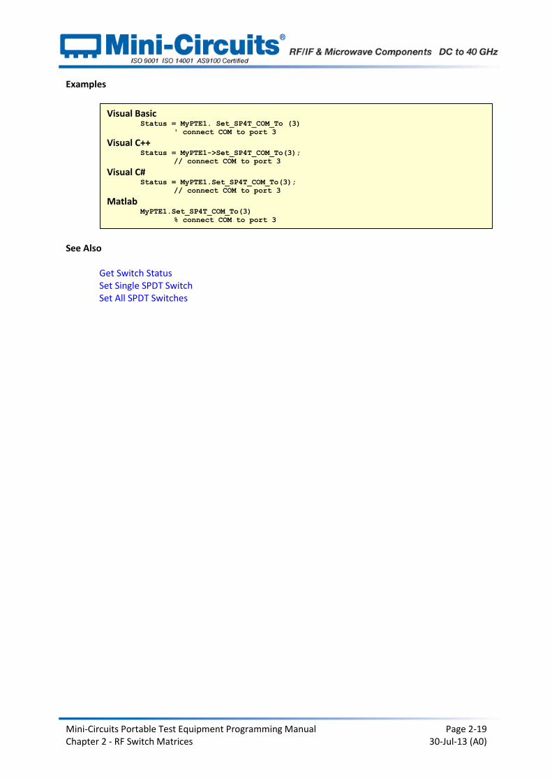
Examples
See Also Get Switch Status Set Single SPDT Switch Set All SPDT Switches
Visual Basic Status = MyPTE1. Set_SP4T_COM_To (3)
' connect COM to port 3 Visual C++
Status = MyPTE1->Set_SP4T_COM_To(3);
// connect COM to port 3 Visual C#
Status = MyPTE1.Set_SP4T_COM_To(3);
// connect COM to port 3 Matlab
MyPTE1.Set_SP4T_COM_To(3)
% connect COM to port 3
Mini-Circuits Portable Test Equipment Programming Manual Page 2-20 Chapter 2 - RF Switch Matrices 30-Jul-13 (A0)
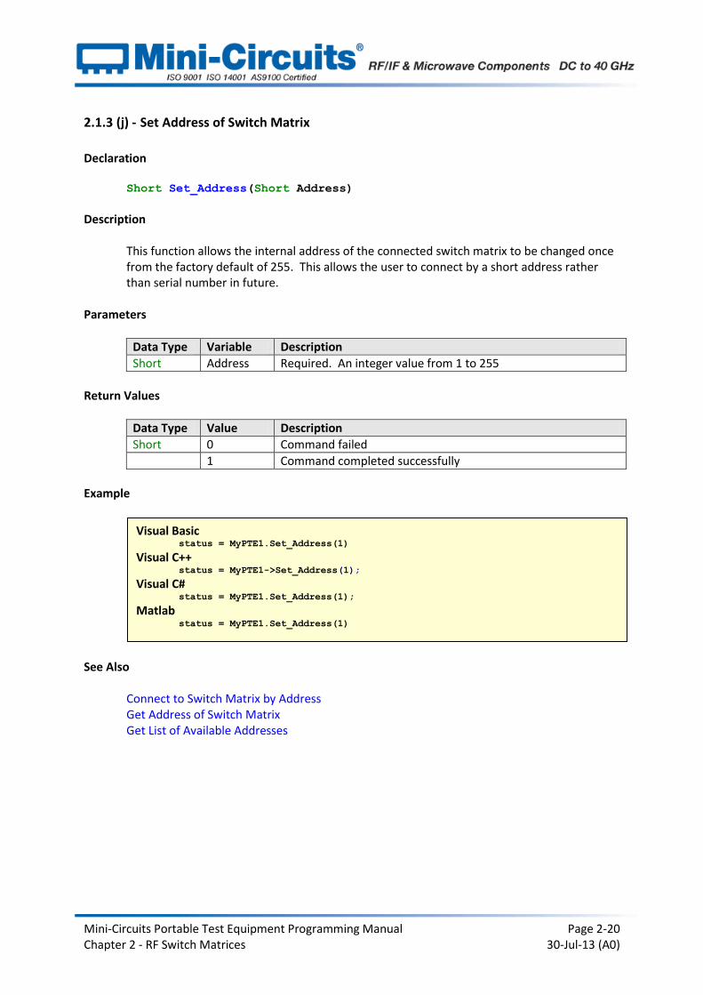
2.1.3 (j) - Set Address of Switch Matrix
Declaration Short Set_Address(Short Address)
Description
This function allows the internal address of the connected switch matrix to be changed once from the factory default of 255. This allows the user to connect by a short address rather than serial number in future.
Parameters
Data Type Variable Description
Short Address Required. An integer value from 1 to 255
Return Values
Data Type Value Description
Short 0 Command failed
1 Command completed successfully
Example
See Also
Connect to Switch Matrix by Address Get Address of Switch Matrix Get List of Available Addresses
Visual Basic status = MyPTE1.Set_Address(1)
Visual C++ status = MyPTE1->Set_Address(1);
Visual C# status = MyPTE1.Set_Address(1);
Matlab status = MyPTE1.Set_Address(1)
Mini-Circuits Portable Test Equipment Programming Manual Page 2-21 Chapter 2 - RF Switch Matrices 30-Jul-13 (A0)
2.1.3 (k) - Get Address of Switch Matrix
Declaration Short Get_Address()
Description
This function returns the address of the connected switch matrix. Parameters
Data Type Variable Description
None
Return Values
Data Type Value Description
Short 0 Command failed
Short 1-255 Address of the switch matrix
Examples
See Also
Connect to Switch Matrix by Address Set Address of Switch Matrix Get List of Available Addresses
Visual Basic addr = MyPTE1.Get_Address()
Visual C++ addr = MyPTE1->Get_Address();
Visual C# addr = MyPTE1.Get_Address();
Matlab addr = MyPTE1.Get_Address
Mini-Circuits Portable Test Equipment Programming Manual Page 2-22 Chapter 2 - RF Switch Matrices 30-Jul-13 (A0)
2.1.3 (l) - Get List of Connected Serial Numbers
Declaration Short Get_Available_SN_List(String SN_List)
Description
This function takes a user defined variable and updates it with a list of serial numbers for all available (currently connected) switch matrices.
Parameters
Data Type Variable Description
String SN_List Required. String variable which the function will update with a list of all available serial numbers, separated by a single space character, for example “11110001 11110002 11110003”.
Return Values
Data Type Value Description
Short 0 Command failed
Short 1 Command completed successfully
Example
See Also Connect to Switch Matrix Get List of Available Addresses
Visual Basic If MyPTE1.Get_Available_SN_List(SN_List) > 0 Then
array_SN() = Split(SN_List, " ")
' Split the list into an array of serial numbers
For i As Integer = 0 To array_SN.Length - 1
' Loop through the array and use each serial number
Next
End If Visual C++
if (MyPTE1 ->Get_Available_SN_List(SN_List) > 0)
{
// split the List into array of SN's
} Visual C#
if (MyPTE1.Get_Available_SN_List(ref(SN_List)) > 0)
{
// split the List into array of SN's
} Matlab
[status, SN_List]= MyPTE1.Get_Available_SN_List(SN_List)
If status > 0 then
{
% split the List into array of SN's
}
Mini-Circuits Portable Test Equipment Programming Manual Page 2-23 Chapter 2 - RF Switch Matrices 30-Jul-13 (A0)
2.1.3 (m) - Get List of Available Addresses
Declaration Short Get_Available_Address_List(String Add_List)
Description
This function takes a user defined variable and updates it with a list of addresses of all connected switch matrices.
Parameters
Data Type Variable Description
String Add_List Required. String variable which the function will update with a list of addresses separated by a single space character, for example, “5 101 254 255”
Return Values
Data Type Value Description
Short 0 Command failed
Short 1 Command completed successfully
Example
See Also
Connect to Switch Matrix by Address Get List of Connected Serial Numbers
Visual Basic If MyPTE1.Get_Available_Add_List(st_Ad_List) > 0 Then
' Get list of available addresses
array_Ad() = Split(st_Ad_List, " ")
' Split the list into an array of addresses
For i As Integer = 0 To array_Ad.Length - 1
' Loop through the array and use each address
Next
End If Visual C++
if (MyPTE1->Get_Available_Address_List(Add_List) > 0);
{ // split the List into array of Addresses
} Visual C#
if (MyPTE1.Get_Available_Address_List(ref(Add_List)) > 0)
{ // split the List into array of Addresses
} Matlab
[status, Add_List]= MyPTE1.Get_Available_Address_List(Add_List)
If status > 0 then
{ % split the List into array of Addresses
}
Mini-Circuits Portable Test Equipment Programming Manual Page 2-24 Chapter 2 - RF Switch Matrices 30-Jul-13 (A0)
2.1.3 (n) - Get Temperature of Switch Matrix
Declaration Float GetDeviceTemperature(Short TSensor)
Description
This function returns the internal temperature of the switch matrix. It does not apply to USB-1SPDT-A18 and USB-1SP4T-A18 since these units have no internal temperature sensors. USB-2SPDT-A18, USB-3SPDT-A18 and USB-4SPDT-A18 each have 2 temperature sensors which can be accessed, USB-8SPDT-A18 has 3. Note: Units with serial numbers earlier than 11108010000 may have a different number of sensors than indicated above.
Parameters
Data Type Variable Description
Short TSensor Required. Short integer variable (1 to 3) to define which temperature sensor to read.
Return Values
Data Type Value Description
Float Temperature The device internal temperature in degrees Celsius
Examples
See Also
Get Heat Alarm
Visual Basic MsgBox ("Temperature is " & MyPTE1.GetDeviceTemperature(2))
' Display a message box with the device temperature Visual C++
MessageBox::Show("Temperature is " + MyPTE1->GetDeviceTemperature(2));
// Display a message box with the device temperature Visual C#
MessageBox.Show("Temperature is " + MyPTE1.GetDeviceTemperature(2));
// Display a message box with the device temperature Matlab
[temp,status]=MyPTE1.GetDeviceTemperature(2)
Msgbox('Temperature is ', temp)
% Display a message box with the device temperature

Mini-Circuits Portable Test Equipment Programming Manual Page 2-25 Chapter 2 - RF Switch Matrices 30-Jul-13 (A0)
2.1.3 (o) - Get Heat Alarm
Declaration Short GetHeatAlarm()
Description
This function applies to USB-2SPDT-A18, USB-3SPDT-A18, USB-4SPDT-A18 and USB-8SPDT-A18, it returns an alarm notification if any of the internal temperature sensors exceeds the factory programmed limits (45°C on PCB or 48°C on the internal switch case).
Parameters
Data Type Variable Description
None
Return Values
Data Type Value Description
Short 0 Temperature within normal range
Short 1 Temperature exceeds specified limit
Examples
See Also
Get Temperature of Switch Matrix
Visual Basic If MyPTE1.GetHeatAlarm > 0 Then
MsgBox ("Temperature has exceeded specified limit")
' Display a warning message
End If Visual C++
if (MyPTE1->GetHeatAlarm() > 0 )
{
MessageBox::Show("Temperature has exceeded specified limit");
// Display a warning message
} Visual C#
if (MyPTE1.GetHeatAlarm() > 0 )
{
MessageBox.Show("Temperature has exceeded specified limit");
// Display a warning message
} Matlab
alarm = MyPTE1.GetHeatAlarm
If alarm > 0 then
{
Msgbox('Temperature has exceeded specified limit')
% Display a warning message
}

Mini-Circuits Portable Test Equipment Programming Manual Page 2-26 Chapter 2 - RF Switch Matrices 30-Jul-13 (A0)
2.1.3 (p) - Get 24V DC Supply Status
Declaration Short Get24V_Indicator()
Description
This function checks whether the required 24V DC power supply is connected. If the DC supply is not connected then all SPDT switches will be in the “COM connected to port 1” state and all SP4T switches will be in the “disconnected” state.
Applies To
Model Serial Numbers
USB-1SPDT-A18 From 11210140015
USB-2SPDT-A18 From 11010030072
USB-3SPDT-A18 From 11210140041
USB-4SPDT-A18 From 11210090035 to 11210090049 and from 11210170001
USB-8SPDT-A18 From 11210150051
USB-1SP4T-A18 All models
Parameters
Data Type Variable Description
None
Return Values
Data Type Value Description
Short 0 24V DC supply not connected
Short 1 24V DC supply is connected

Mini-Circuits Portable Test Equipment Programming Manual Page 2-27 Chapter 2 - RF Switch Matrices 30-Jul-13 (A0)
Examples
See Also Get Fan Status
Visual Basic If MyPTE1.Get24V_Indicator > 0 Then
' 24V supply connected
End If Visual C++
if (MyPTE1-> Get24V_Indicator() > 0 )
{
// 24V supply connected
} Visual C#
if (MyPTE1.Get_24V_Indicator() > 0)
{
// 24V supply connected
} Matlab
dcstatus = MyPTE1.Get24V_Indicator
If dcstatus > 0 then
{
% 24V supply connected
}

Mini-Circuits Portable Test Equipment Programming Manual Page 2-28 Chapter 2 - RF Switch Matrices 30-Jul-13 (A0)
2.1.3 (q) - Get Fan Status
Declaration Short Get_FAN_Indicator()
Description
This function checks whether the internal fan (or fans) are currently operating. Applies To
Model Serial Numbers
USB-1SPDT-A18 From 11108010000
USB-2SPDT-A18 From 11108010000
USB-3SPDT-A18 From 11108010000
USB-4SPDT-A18 From 11108010000
USB-8SPDT-A18 From 11108010000
USB-1SP4T-A18 All models
Parameters
Data Type Variable Description
None
Return Values
Data Type Value Description
Short 0 Fan not currently operating
Short 1 Fan operating
Examples
Visual Basic If MyPTE1.Get_FAN_Indicator > 0 Then
' Fan is currently operating
End If Visual C++
if (MyPTE1-> Get_FAN_Indicator() > 0 )
{
// Fan is currently operating
} Visual C#
if (MyPTE1.Get_FAN_Indicator() > 0)
{
// Fan is currently operating
} Matlab
fanstatus = MyPTE1.Get_FAN_Indicator
If fanstatus > 0 then
{
% Fan is currently operating
}
Mini-Circuits Portable Test Equipment Programming Manual Page 2-29 Chapter 2 - RF Switch Matrices 30-Jul-13 (A0)
See Also
Check Internal Temperature Get Heat Alarm
Mini-Circuits Portable Test Equipment Programming Manual Page 2-30 Chapter 2 - RF Switch Matrices 30-Jul-13 (A0)
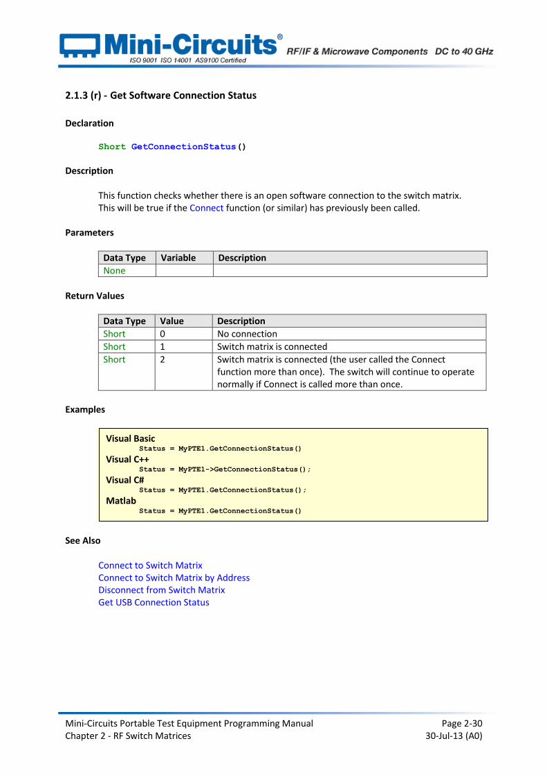
2.1.3 (r) - Get Software Connection Status
Declaration Short GetConnectionStatus()
Description
This function checks whether there is an open software connection to the switch matrix. This will be true if the Connect function (or similar) has previously been called.
Parameters
Data Type Variable Description
None
Return Values
Data Type Value Description
Short 0 No connection
Short 1 Switch matrix is connected
Short 2 Switch matrix is connected (the user called the Connect function more than once). The switch will continue to operate normally if Connect is called more than once.
Examples
See Also Connect to Switch Matrix Connect to Switch Matrix by Address Disconnect from Switch Matrix Get USB Connection Status
Visual Basic Status = MyPTE1.GetConnectionStatus()
Visual C++ Status = MyPTE1->GetConnectionStatus();
Visual C# Status = MyPTE1.GetConnectionStatus();
Matlab Status = MyPTE1.GetConnectionStatus()
Mini-Circuits Portable Test Equipment Programming Manual Page 2-31 Chapter 2 - RF Switch Matrices 30-Jul-13 (A0)
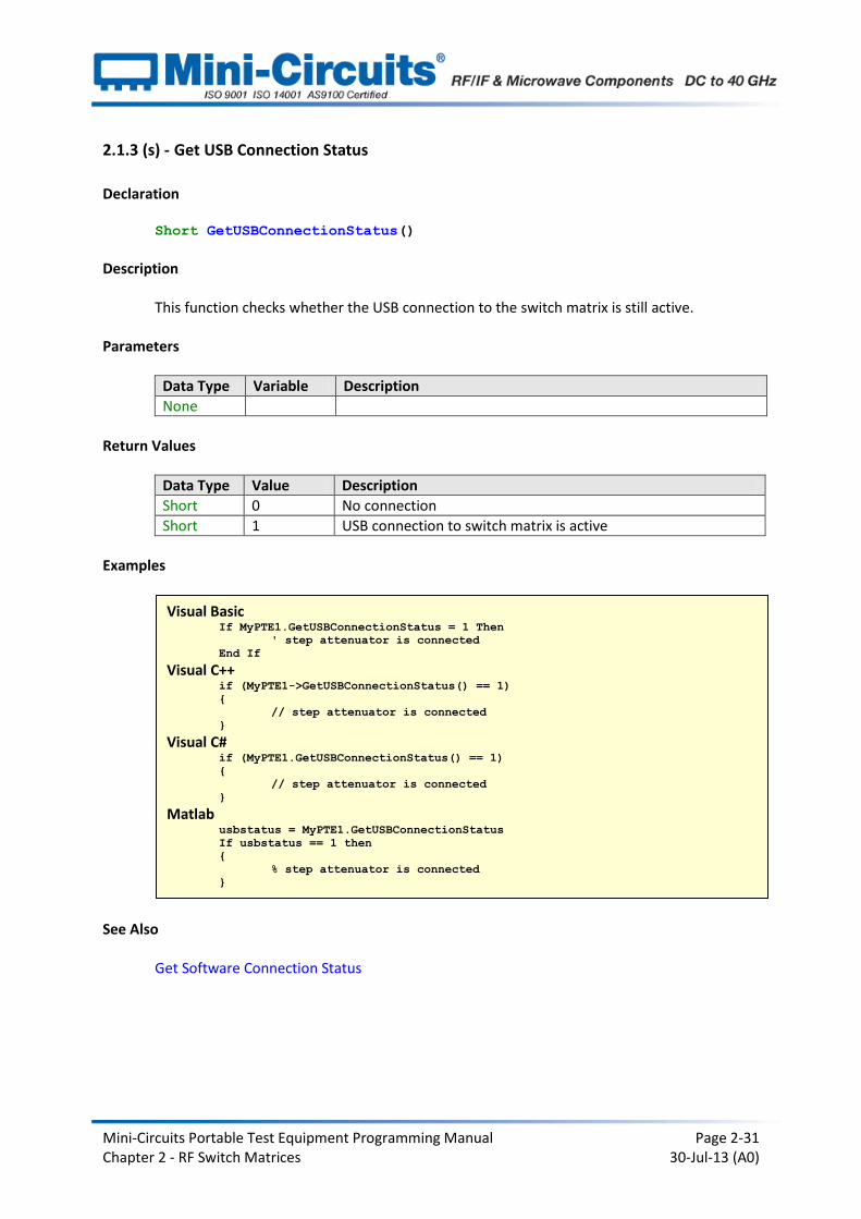
2.1.3 (s) - Get USB Connection Status
Declaration Short GetUSBConnectionStatus()
Description
This function checks whether the USB connection to the switch matrix is still active. Parameters
Data Type Variable Description
None
Return Values
Data Type Value Description
Short 0 No connection
Short 1 USB connection to switch matrix is active
Examples
See Also Get Software Connection Status
Visual Basic If MyPTE1.GetUSBConnectionStatus = 1 Then
' step attenuator is connected
End If Visual C++
if (MyPTE1->GetUSBConnectionStatus() == 1)
{
// step attenuator is connected
} Visual C#
if (MyPTE1.GetUSBConnectionStatus() == 1)
{
// step attenuator is connected
} Matlab
usbstatus = MyPTE1.GetUSBConnectionStatus
If usbstatus == 1 then
{
% step attenuator is connected
}
Mini-Circuits Portable Test Equipment Programming Manual Page 2-32 Chapter 2 - RF Switch Matrices 30-Jul-13 (A0)
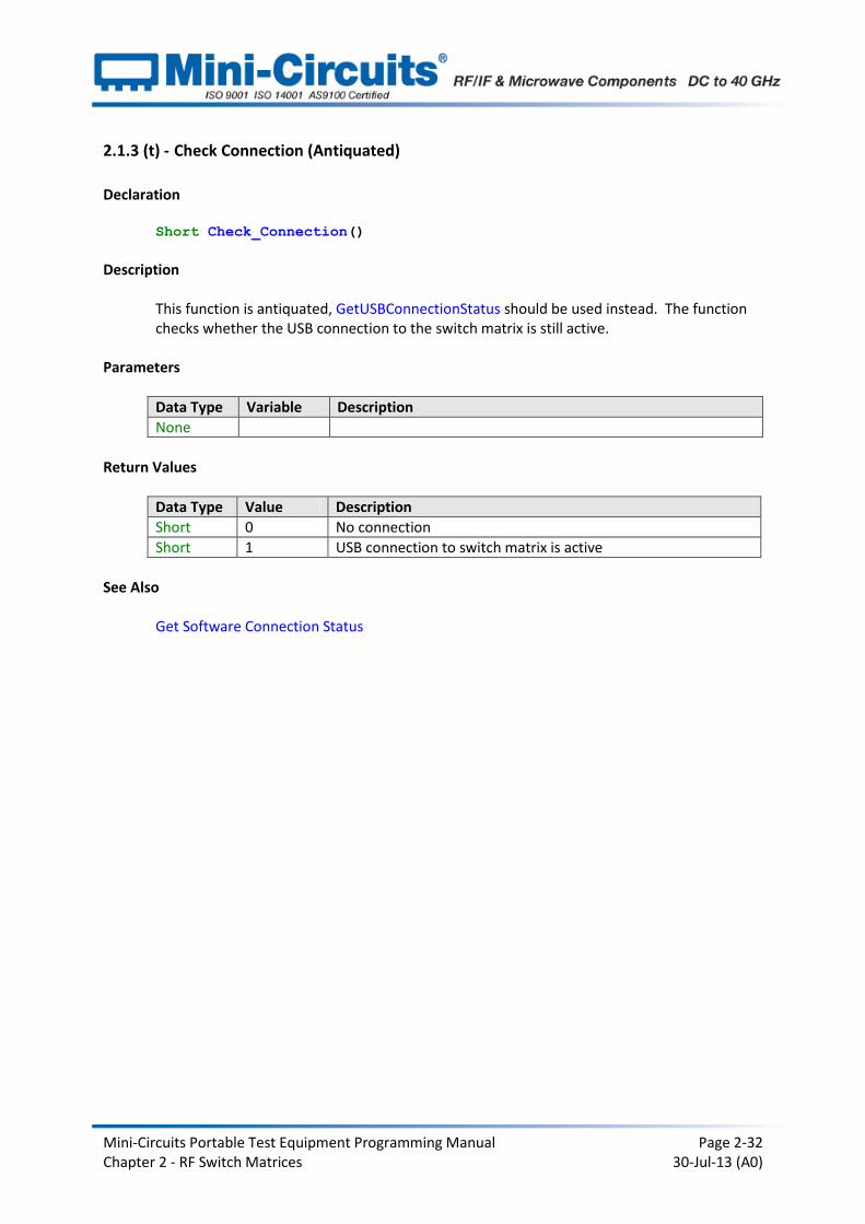
2.1.3 (t) - Check Connection (Antiquated)
Declaration Short Check_Connection()
Description
This function is antiquated, GetUSBConnectionStatus should be used instead. The function checks whether the USB connection to the switch matrix is still active.
Parameters
Data Type Variable Description
None
Return Values
Data Type Value Description
Short 0 No connection
Short 1 USB connection to switch matrix is active
See Also Get Software Connection Status

Mini-Circuits Portable Test Equipment Programming Manual Page 2-33 Chapter 2 - RF Switch Matrices 30-Jul-13 (A0)
2.1.3 (u) - Get USB Device Name
Declaration String GetUSBDeviceName()
Description
This function is for advanced users to identify the USB device name of the switch matrix for direct communication.
Parameters
Data Type Variable Description
None
Return Values
Data Type Value Description
String Name Device name of the switch matrix
Examples
Visual Basic usbname = MyPTE1.GetUSBDeviceName()
' Return the USB device name as a string Visual C++
usbname = MyPTE1->GetUSBDeviceName();
// Return the USB device name as a string Visual C#
usbname = MyPTE1.GetUSBDeviceName();
// Return the USB device name as a string Matlab
usbname = MyPTE1.GetUSBDeviceName
% Return the USB device name as a string
Mini-Circuits Portable Test Equipment Programming Manual Page 2-34 Chapter 2 - RF Switch Matrices 30-Jul-13 (A0)
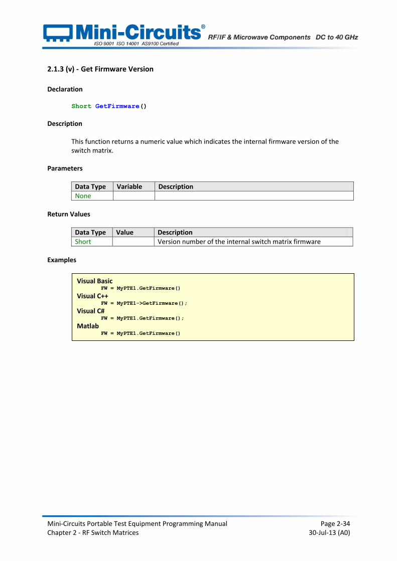
2.1.3 (v) - Get Firmware Version
Declaration Short GetFirmware()
Description
This function returns a numeric value which indicates the internal firmware version of the switch matrix.
Parameters
Data Type Variable Description
None
Return Values
Data Type Value Description
Short Version number of the internal switch matrix firmware
Examples
Visual Basic FW = MyPTE1.GetFirmware()
Visual C++ FW = MyPTE1->GetFirmware();
Visual C# FW = MyPTE1.GetFirmware();
Matlab FW = MyPTE1.GetFirmware()
Mini-Circuits Portable Test Equipment Programming Manual Page 2-35 Chapter 2 - RF Switch Matrices 30-Jul-13 (A0)
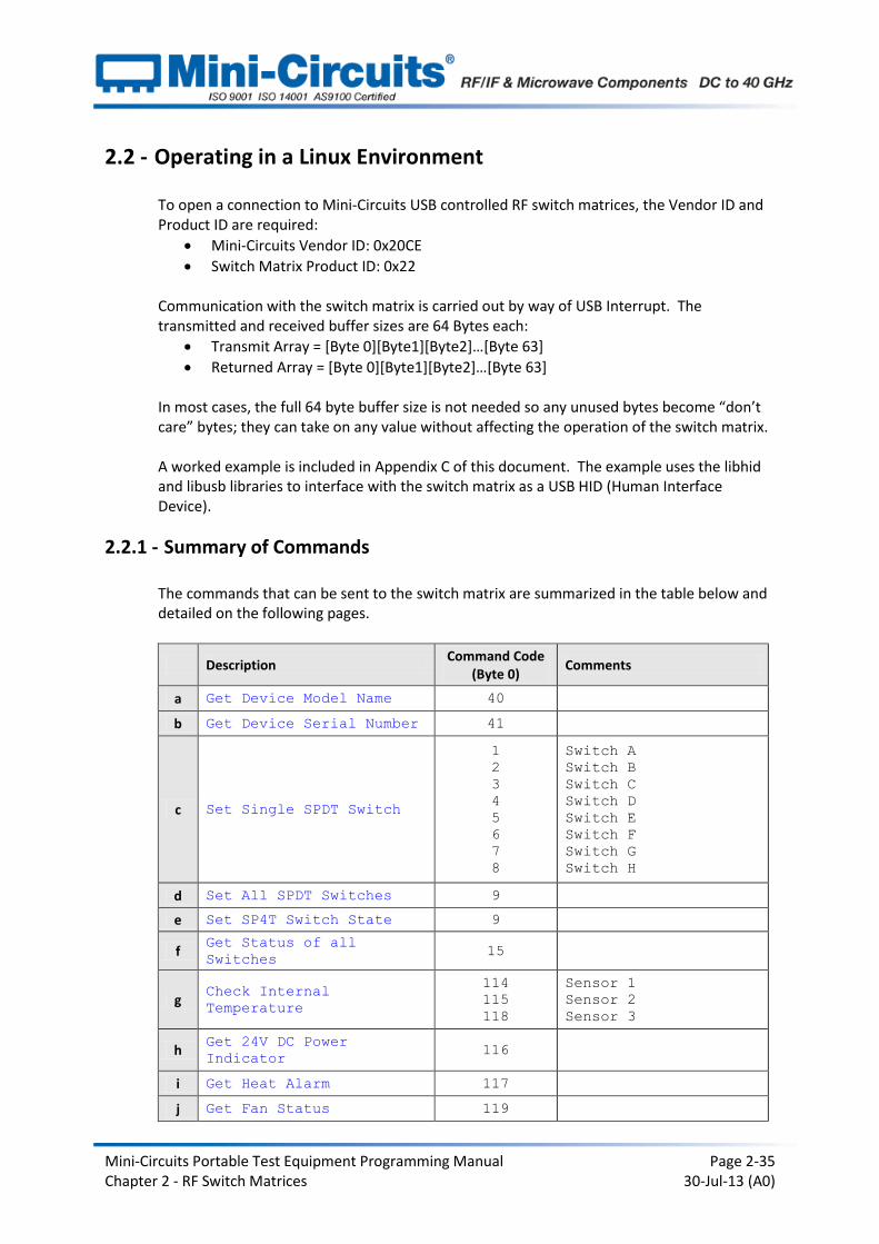
2.2 - Operating in a Linux Environment
To open a connection to Mini-Circuits USB controlled RF switch matrices, the Vendor ID and Product ID are required:
Mini-Circuits Vendor ID: 0x20CE
Switch Matrix Product ID: 0x22 Communication with the switch matrix is carried out by way of USB Interrupt. The transmitted and received buffer sizes are 64 Bytes each:
Transmit Array = [Byte 0][Byte1][Byte2]…[Byte 63]
Returned Array = [Byte 0][Byte1][Byte2]…[Byte 63] In most cases, the full 64 byte buffer size is not needed so any unused bytes become “don’t care” bytes; they can take on any value without affecting the operation of the switch matrix. A worked example is included in Appendix C of this document. The example uses the libhid and libusb libraries to interface with the switch matrix as a USB HID (Human Interface Device).
2.2.1 - Summary of Commands
The commands that can be sent to the switch matrix are summarized in the table below and detailed on the following pages.
Description Command Code
(Byte 0) Comments
a Get Device Model Name 40
b Get Device Serial Number 41
c Set Single SPDT Switch
1
2
3
4
5
6
7
8
Switch A
Switch B
Switch C
Switch D
Switch E
Switch F
Switch G
Switch H
d Set All SPDT Switches 9
e Set SP4T Switch State 9
f Get Status of all
Switches 15
g Check Internal
Temperature
114
115
118
Sensor 1
Sensor 2
Sensor 3
h Get 24V DC Power
Indicator 116
i Get Heat Alarm 117
j Get Fan Status 119

Mini-Circuits Portable Test Equipment Programming Manual Page 2-36 Chapter 2 - RF Switch Matrices 30-Jul-13 (A0)
2.2.2 - Detailed Description of Commands
2.2.2 (a) - Get Device Model Name
Description
This function determines the Mini-Circuits part number of the connected switch matrix.
Send code 40 in BYTE0 of the transmit array. BYTE1 through to BYTE63 are don’t care bytes and can be any value. The model name is represented as a series of ASCII characters in the returned array, starting from BYTE1. The final ASCII character is contained in the byte immediately preceding the first zero value byte. All subsequent bytes up to BYTE63 are “don’t care” bytes and could be any value.
Transmit Array Returned Array
Byte Byte 0 Byte 1 Byte 2 … Byte (N-1) Byte N
Description Code First
Char
Second
Char …
Last
Char
End
Marker
Value 40 ASCII ASCII … ASCII 0
Example
The following array would be returned for Mini-Circuits’ USB-4SPDT-A18 switch matrix. See Appendix A for conversions between decimal, binary and ASCII characters.
Byte Byte 0 Byte 1 Byte 2 Byte 3 Byte 4 Byte 5 Byte 6
Description Code Char 1 Char 2 Char 3 Char 4 Char 5 Char 6
Value 40 85 83 42 45 52 83
ASCII Character N/A U S B - 4 S
Byte Byte 7 Byte 8 Byte 9 Byte 10 Byte 11 Byte 12 Byte 13
Description Char 7 Char 8 Char 9 Char 10 Char 11 Char 12 Char 13
Value 80 68 84 45 65 49 56
ASCII Character P D T - A 1 8
Byte Byte 14
Description End
Marker
Value 0
ASCII Character N/A
Byte Byte 0
Description Code
Value 40
Mini-Circuits Portable Test Equipment Programming Manual Page 2-37 Chapter 2 - RF Switch Matrices 30-Jul-13 (A0)
See Also Get Device Serial Number

Mini-Circuits Portable Test Equipment Programming Manual Page 2-38 Chapter 2 - RF Switch Matrices 30-Jul-13 (A0)
2.2.2 (b) - Get Device Serial Number
Description
This function determines the serial number of the connected switch matrix.
Send code 41 in BYTE0 of the transmit array. BYTE1 through to BYTE63 are “don’t care” bytes and can be any value. The serial number is represented as a series of ASCII characters in the returned array, starting from BYTE1. The final ASCII character is contained in the byte immediately preceding the first zero value byte. All subsequent bytes up to BYTE63 are “don’t care” bytes and could be any value.
Transmit Array
Byte Byte 0
Description Code
Value 41
Returned Array
Byte Byte 0 Byte 1 Byte 2 … Byte (N-1) Byte N
Description Code First
Char
Second
Char …
Last
Char
End
Marker
Value 41 ASCII ASCII … ASCII 0
Example
The following example indicates that the current switch matrix has serial number 1100040023. See Appendix A for conversions between decimal, binary and ASCII characters.
Byte Byte 0 Byte 1 Byte 2 Byte 3 Byte 4 Byte 5 Byte 6
Description Code Char 1 Char 2 Char 3 Char 4 Char 5 Char 6
Value 41 49 49 48 48 48 52
ASCII Character N/A 1 1 0 0 0 4
Byte Byte 7 Byte 8 Byte 9 Byte 10 Byte 11
Description Char 7 Char 8 Char 9 Char 10 End
Marker
Value 48 48 50 51 0
ASCII Character 0 0 2 3 N/A
See Also Get Device Model Name
Mini-Circuits Portable Test Equipment Programming Manual Page 2-39 Chapter 2 - RF Switch Matrices 30-Jul-13 (A0)
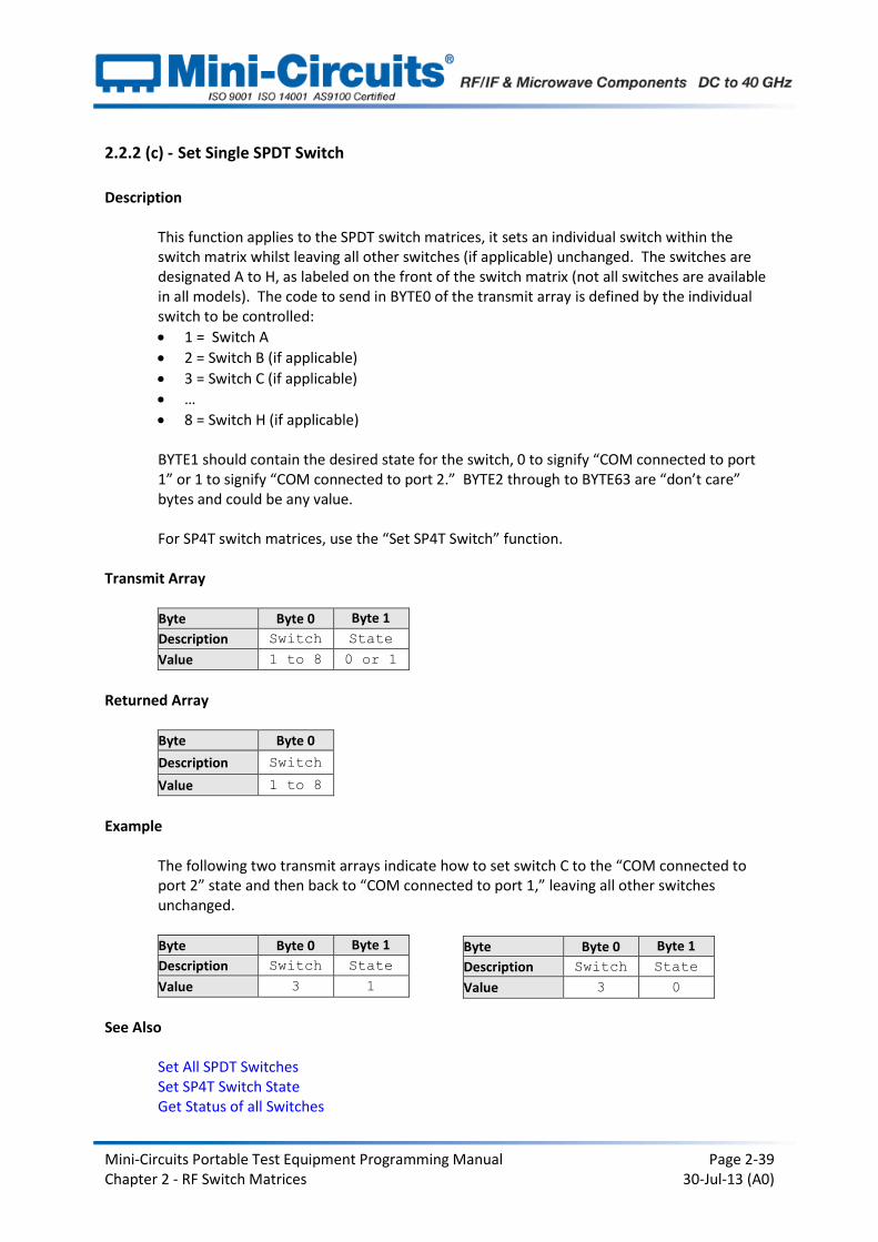
2.2.2 (c) - Set Single SPDT Switch
Description
This function applies to the SPDT switch matrices, it sets an individual switch within the switch matrix whilst leaving all other switches (if applicable) unchanged. The switches are designated A to H, as labeled on the front of the switch matrix (not all switches are available in all models). The code to send in BYTE0 of the transmit array is defined by the individual switch to be controlled:
1 = Switch A
2 = Switch B (if applicable)
3 = Switch C (if applicable)
…
8 = Switch H (if applicable)
BYTE1 should contain the desired state for the switch, 0 to signify “COM connected to port 1” or 1 to signify “COM connected to port 2.” BYTE2 through to BYTE63 are “don’t care” bytes and could be any value. For SP4T switch matrices, use the “Set SP4T Switch” function.
Transmit Array
Byte Byte 0 Byte 1
Description Switch State
Value 1 to 8 0 or 1
Returned Array
Byte Byte 0
Description Switch
Value 1 to 8
Example
The following two transmit arrays indicate how to set switch C to the “COM connected to port 2” state and then back to “COM connected to port 1,” leaving all other switches unchanged.
Byte Byte 0 Byte 1
Description Switch State
Value 3 1
See Also Set All SPDT Switches Set SP4T Switch State Get Status of all Switches
Byte Byte 0 Byte 1
Description Switch State
Value 3 0
Mini-Circuits Portable Test Equipment Programming Manual Page 2-40 Chapter 2 - RF Switch Matrices 30-Jul-13 (A0)
2.2.2 (d) - Set All SPDT Switches
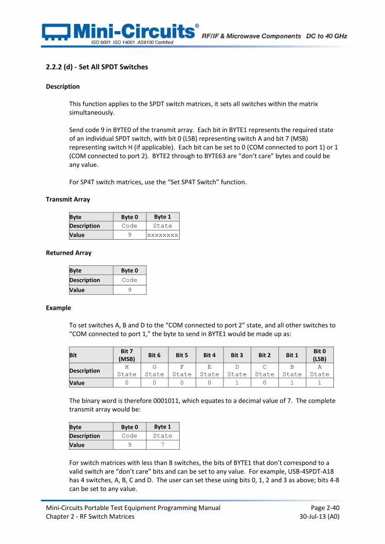
Description
This function applies to the SPDT switch matrices, it sets all switches within the matrix simultaneously. Send code 9 in BYTE0 of the transmit array. Each bit in BYTE1 represents the required state of an individual SPDT switch, with bit 0 (LSB) representing switch A and bit 7 (MSB) representing switch H (if applicable). Each bit can be set to 0 (COM connected to port 1) or 1 (COM connected to port 2). BYTE2 through to BYTE63 are “don’t care” bytes and could be any value. For SP4T switch matrices, use the “Set SP4T Switch” function.
Transmit Array
Byte Byte 0 Byte 1
Description Code State
Value 9 xxxxxxxx
Returned Array
Byte Byte 0
Description Code
Value 9
Example
To set switches A, B and D to the “COM connected to port 2” state, and all other switches to “COM connected to port 1,” the byte to send in BYTE1 would be made up as:
Bit Bit 7
(MSB) Bit 6 Bit 5 Bit 4 Bit 3 Bit 2 Bit 1
Bit 0 (LSB)
Description H
State
G
State
F
State
E
State
D
State
C
State
B
State
A
State
Value 0 0 0 0 1 0 1 1
The binary word is therefore 0001011, which equates to a decimal value of 7. The complete transmit array would be: Byte Byte 0 Byte 1
Description Code State
Value 9 7
For switch matrices with less than 8 switches, the bits of BYTE1 that don’t correspond to a valid switch are “don’t care” bits and can be set to any value. For example, USB-4SPDT-A18 has 4 switches, A, B, C and D. The user can set these using bits 0, 1, 2 and 3 as above; bits 4-8 can be set to any value.

Mini-Circuits Portable Test Equipment Programming Manual Page 2-41 Chapter 2 - RF Switch Matrices 30-Jul-13 (A0)
See Also
Set All SPDT Switches Set SP4T Switch State Get Status of all Switches
Mini-Circuits Portable Test Equipment Programming Manual Page 2-42 Chapter 2 - RF Switch Matrices 30-Jul-13 (A0)
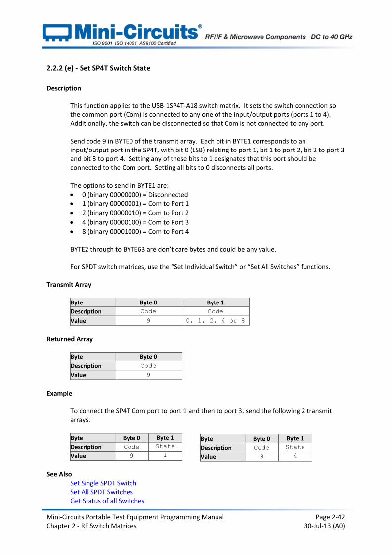
2.2.2 (e) - Set SP4T Switch State
Description
This function applies to the USB-1SP4T-A18 switch matrix. It sets the switch connection so the common port (Com) is connected to any one of the input/output ports (ports 1 to 4). Additionally, the switch can be disconnected so that Com is not connected to any port. Send code 9 in BYTE0 of the transmit array. Each bit in BYTE1 corresponds to an input/output port in the SP4T, with bit 0 (LSB) relating to port 1, bit 1 to port 2, bit 2 to port 3 and bit 3 to port 4. Setting any of these bits to 1 designates that this port should be connected to the Com port. Setting all bits to 0 disconnects all ports. The options to send in BYTE1 are:
0 (binary 00000000) = Disconnected
1 (binary 00000001) = Com to Port 1
2 (binary 00000010) = Com to Port 2
4 (binary 00000100) = Com to Port 3
8 (binary 00001000) = Com to Port 4 BYTE2 through to BYTE63 are don’t care bytes and could be any value. For SPDT switch matrices, use the “Set Individual Switch” or “Set All Switches” functions.
Transmit Array
Byte Byte 0 Byte 1
Description Code Code
Value 9 0, 1, 2, 4 or 8
Returned Array
Byte Byte 0
Description Code
Value 9
Example
To connect the SP4T Com port to port 1 and then to port 3, send the following 2 transmit arrays. Byte Byte 0 Byte 1
Description Code State
Value 9 1
See Also
Set Single SPDT Switch Set All SPDT Switches Get Status of all Switches
Byte Byte 0 Byte 1
Description Code State
Value 9 4

Mini-Circuits Portable Test Equipment Programming Manual Page 2-43 Chapter 2 - RF Switch Matrices 30-Jul-13 (A0)
2.2.2 (f) - Get States of all Switches
Description
This function confirms the current state of all switches within the switch matrix. Send code 15 in BYTE0 of the transmit array. BYTE1 through to BYTE63 are “don’t care” bytes and can be any value. The returned array differs between the SPDT and SP4T switch matrices. For SPDT switch matrices (USB-1SPDT-A18, USB-2SPDT-A18, USB-3SPDT-A18, USB-4SPDT-A18 and USB-8SPDT-A18):
Each bit in BYTE1 of the return array represents the state of an individual SPDT switch, with bit 0 (LSB) representing switch A and bit 7 (MSB) representing switch H (if applicable).
Each bit will have the value 0 (COM connected to port 1) or 1 (COM connected to port 2).
For USB-1SPDT-A18, the possible values returned in BYTE1 are:
0 (binary 00000000) = Disconnected
1 (binary 00000001) = Com to Port 1
2 (binary 00000010) = Com to Port 2
4 (binary 00000100) = Com to Port 3
8 (binary 00001000) = Com to Port 4
Transmit Array (All Models)
Byte Byte 0
Description Code
Value 15
Returned Array (All Models)
Byte Byte 0 Byte 1
Description Code State
Value 15 xxxxxxxx

Mini-Circuits Portable Test Equipment Programming Manual Page 2-44 Chapter 2 - RF Switch Matrices 30-Jul-13 (A0)
Example (SPDT Matrices)
If switches A, B and D are in the “COM connected to port 2” state, with all others in the “COM connected to port 1 state,” the returned array would be: Byte Byte 0 Byte 1
Description Code State
Value 15 7
The decimal value of 7 equates to a binary word of 0001011. The states of the individual switches can therefore be represented as:
Bit Bit 7
(MSB) Bit 6 Bit 5 Bit 4 Bit 3 Bit 2 Bit 1
Bit 0 (LSB)
Description H
State
G
State
F
State
E
State
D
State
C
State
B
State
A
State
Value 0 0 0 0 1 0 1 1
For switch matrices with less than 8 switches, the bits of BYTE1 that don’t correspond to a switch are “don’t care” bits and could be any value. For example, USB-4SPDT-A18 has 4 switches, A, B, C and D; bits 0, 1, 2 and 3 represent their states; bits 4-8 could be any value.
Example (USB-1SP4T-A18)
If the SP4T Com port is connected to port 3, the returned array would be: Byte Byte 0 Byte 1
Description Code State
Value 15 4
See Also
Set Single SPDT Switch Set All SPDT Switches Set SP4T Switch State
Mini-Circuits Portable Test Equipment Programming Manual Page 2-45 Chapter 2 - RF Switch Matrices 30-Jul-13 (A0)
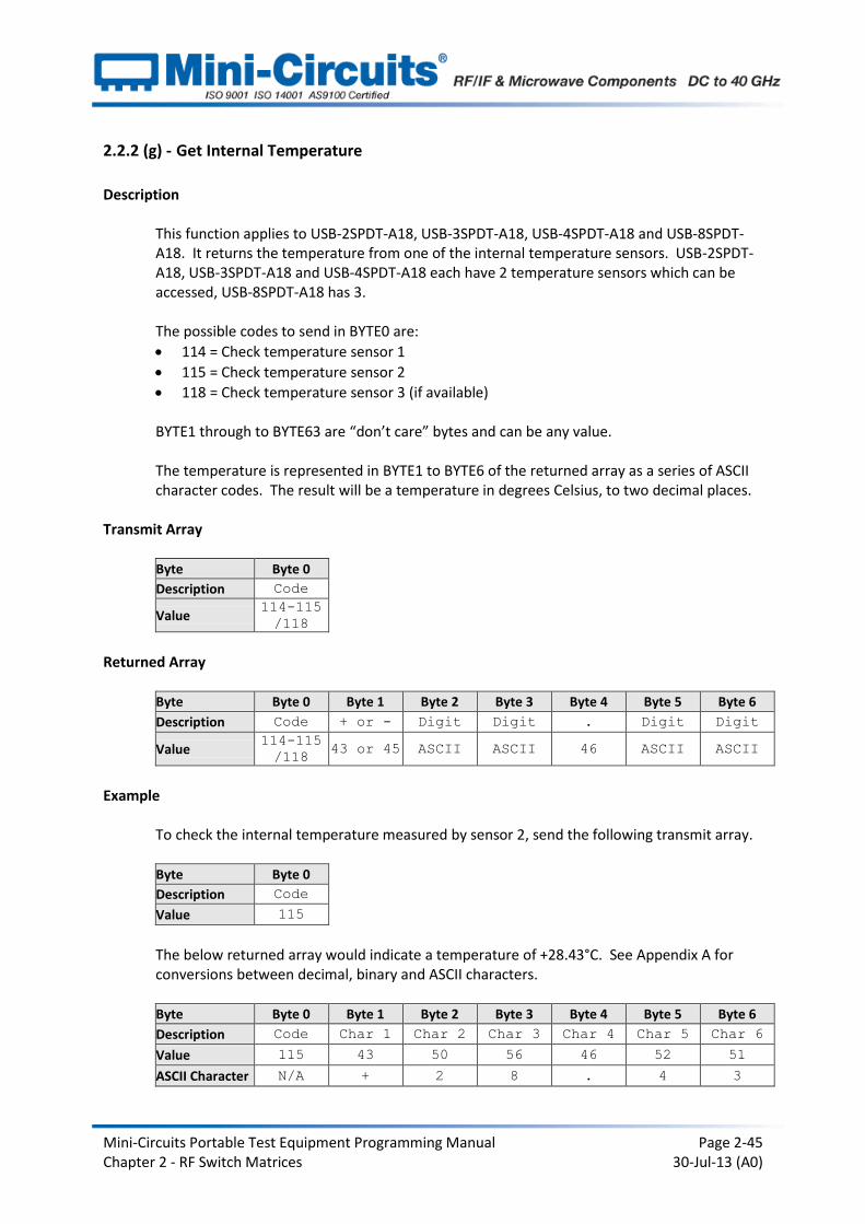
2.2.2 (g) - Get Internal Temperature
Description
This function applies to USB-2SPDT-A18, USB-3SPDT-A18, USB-4SPDT-A18 and USB-8SPDT-A18. It returns the temperature from one of the internal temperature sensors. USB-2SPDT-A18, USB-3SPDT-A18 and USB-4SPDT-A18 each have 2 temperature sensors which can be accessed, USB-8SPDT-A18 has 3.
The possible codes to send in BYTE0 are:
114 = Check temperature sensor 1
115 = Check temperature sensor 2
118 = Check temperature sensor 3 (if available) BYTE1 through to BYTE63 are “don’t care” bytes and can be any value. The temperature is represented in BYTE1 to BYTE6 of the returned array as a series of ASCII character codes. The result will be a temperature in degrees Celsius, to two decimal places.
Transmit Array
Byte Byte 0
Description Code
Value 114-115
/118
Returned Array
Byte Byte 0 Byte 1 Byte 2 Byte 3 Byte 4 Byte 5 Byte 6
Description Code + or - Digit Digit . Digit Digit
Value 114-115
/118 43 or 45 ASCII ASCII 46 ASCII ASCII
Example
To check the internal temperature measured by sensor 2, send the following transmit array. Byte Byte 0
Description Code
Value 115
The below returned array would indicate a temperature of +28.43°C. See Appendix A for conversions between decimal, binary and ASCII characters.
Byte Byte 0 Byte 1 Byte 2 Byte 3 Byte 4 Byte 5 Byte 6
Description Code Char 1 Char 2 Char 3 Char 4 Char 5 Char 6
Value 115 43 50 56 46 52 51
ASCII Character N/A + 2 8 . 4 3

Mini-Circuits Portable Test Equipment Programming Manual Page 2-46 Chapter 2 - RF Switch Matrices 30-Jul-13 (A0)
See Also Get Heat Alarm Get Fan Status

Mini-Circuits Portable Test Equipment Programming Manual Page 2-47 Chapter 2 - RF Switch Matrices 30-Jul-13 (A0)
2.2.2 (h) - Get 24V DC Power Status
Description
This function checks whether the external 24V DC power supply is connected to the switch matrix. Send code 116 in BYTE0 of the transmit array (BYTE1 through BYTE63 can be any value). BYTE1 of the returned array will be 1 to indicate the 24V supply is connected, or 0 to indicate the supply is not connected Note: This function applies to switch matrices with firmware version B3 or newer and serial number 12110200000 or higher.
Transmit Array
Byte Byte 0
Description Code
Value 116
Returned Array
Byte Byte 0 Byte 1
Description Code DC
Status
Value 116 0 or 1
Example
The following return array would indicate the 24V DC supply is not connected: Byte Byte 0 Byte 1
Description Code DC
Status
Value 116 0
The following return array would indicate the 24V DC supply is connected: Byte Byte 0 Byte 1
Description Code DC
Status
Value 116 1
See Also Get Heat Alarm Get Fan Status
Mini-Circuits Portable Test Equipment Programming Manual Page 2-48 Chapter 2 - RF Switch Matrices 30-Jul-13 (A0)
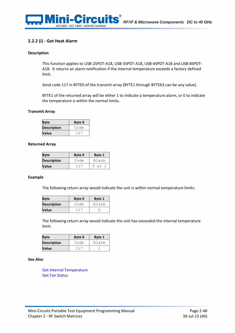
2.2.2 (i) - Get Heat Alarm
Description
This function applies to USB-2SPDT-A18, USB-3SPDT-A18, USB-4SPDT-A18 and USB-8SPDT-A18. It returns an alarm notification if the internal temperature exceeds a factory defined limit.
Send code 117 in BYTE0 of the transmit array (BYTE1 through BYTE63 can be any value). BYTE1 of the returned array will be either 1 to indicate a temperature alarm, or 0 to indicate the temperature is within the normal limits.
Transmit Array
Byte Byte 0
Description Code
Value 117
Returned Array
Byte Byte 0 Byte 1
Description Code Alarm
Value 117 0 or 1
Example
The following return array would indicate the unit is within normal temperature limits: Byte Byte 0 Byte 1
Description Code Alarm
Value 117 0
The following return array would indicate the unit has exceeded the internal temperature limit: Byte Byte 0 Byte 1
Description Code Alarm
Value 117 1
See Also Get Internal Temperature Get Fan Status
Mini-Circuits Portable Test Equipment Programming Manual Page 2-49 Chapter 2 - RF Switch Matrices 30-Jul-13 (A0)
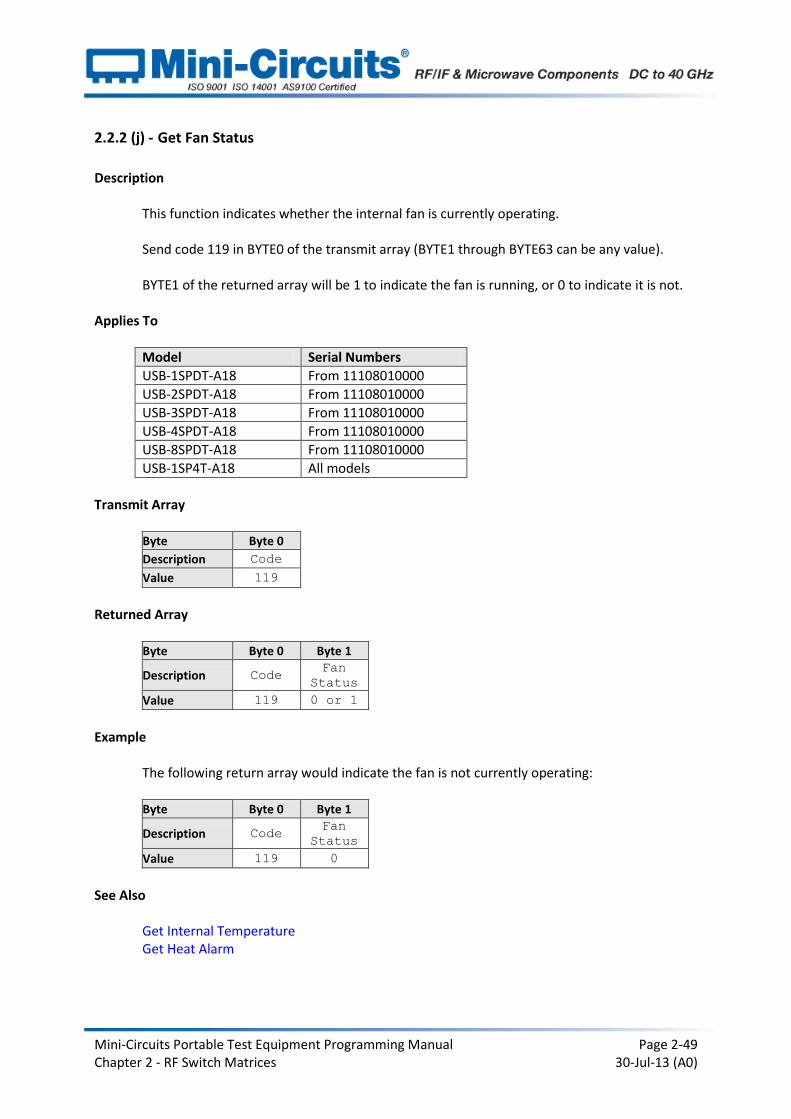
2.2.2 (j) - Get Fan Status
Description
This function indicates whether the internal fan is currently operating.
Send code 119 in BYTE0 of the transmit array (BYTE1 through BYTE63 can be any value). BYTE1 of the returned array will be 1 to indicate the fan is running, or 0 to indicate it is not.
Applies To
Model Serial Numbers
USB-1SPDT-A18 From 11108010000
USB-2SPDT-A18 From 11108010000
USB-3SPDT-A18 From 11108010000
USB-4SPDT-A18 From 11108010000
USB-8SPDT-A18 From 11108010000
USB-1SP4T-A18 All models
Transmit Array
Byte Byte 0
Description Code
Value 119
Returned Array
Byte Byte 0 Byte 1
Description Code Fan
Status
Value 119 0 or 1
Example
The following return array would indicate the fan is not currently operating: Byte Byte 0 Byte 1
Description Code Fan
Status
Value 119 0
See Also Get Internal Temperature Get Heat Alarm
Mini-Circuits Portable Test Equipment Programming Manual Page 2-50 Chapter 2 - RF Switch Matrices 30-Jul-13 (A0)
2.3 - Ethernet Control over IP Networks
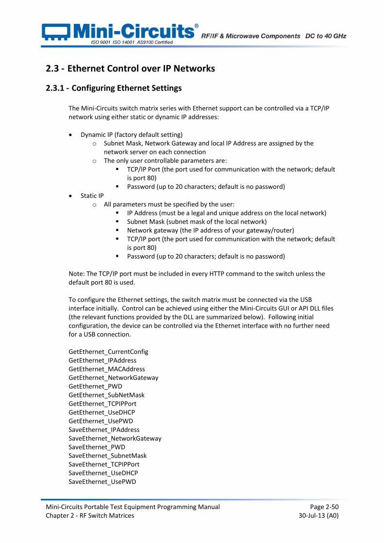
2.3.1 - Configuring Ethernet Settings
The Mini-Circuits switch matrix series with Ethernet support can be controlled via a TCP/IP network using either static or dynamic IP addresses:
Dynamic IP (factory default setting) o Subnet Mask, Network Gateway and local IP Address are assigned by the
network server on each connection o The only user controllable parameters are:
TCP/IP Port (the port used for communication with the network; default is port 80)
Password (up to 20 characters; default is no password)
Static IP o All parameters must be specified by the user:
IP Address (must be a legal and unique address on the local network) Subnet Mask (subnet mask of the local network) Network gateway (the IP address of your gateway/router) TCP/IP port (the port used for communication with the network; default
is port 80) Password (up to 20 characters; default is no password)
Note: The TCP/IP port must be included in every HTTP command to the switch unless the default port 80 is used.
To configure the Ethernet settings, the switch matrix must be connected via the USB interface initially. Control can be achieved using either the Mini-Circuits GUI or API DLL files (the relevant functions provided by the DLL are summarized below). Following initial configuration, the device can be controlled via the Ethernet interface with no further need for a USB connection.
GetEthernet_CurrentConfig GetEthernet_IPAddress GetEthernet_MACAddress GetEthernet_NetworkGateway GetEthernet_PWD GetEthernet_SubNetMask GetEthernet_TCPIPPort GetEthernet_UseDHCP GetEthernet_UsePWD SaveEthernet_IPAddress SaveEthernet_NetworkGateway SaveEthernet_PWD SaveEthernet_SubnetMask SaveEthernet_TCPIPPort SaveEthernet_UseDHCP SaveEthernet_UsePWD
Mini-Circuits Portable Test Equipment Programming Manual Page 2-51 Chapter 2 - RF Switch Matrices 30-Jul-13 (A0)
2.3.2 - Ethernet Communication
Communication over Ethernet is accomplished using HTTP Get/Post commands. This functionality is commonly supported and simple to implement in most programming languages. Any Internet browser can be used as a console/tester by typing the HTTP command directly into the address bar.
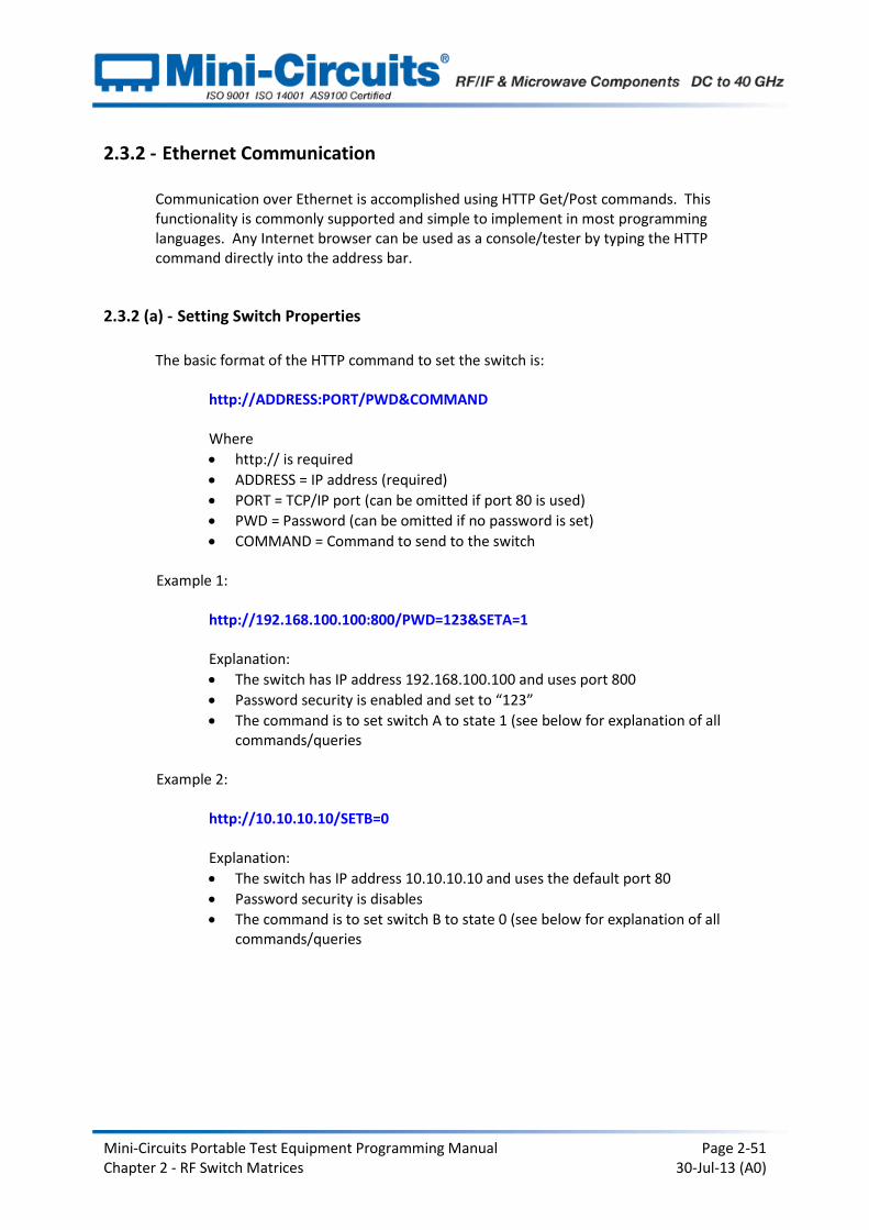
2.3.2 (a) - Setting Switch Properties
The basic format of the HTTP command to set the switch is:
http://ADDRESS:PORT/PWD&COMMAND Where
http:// is required
ADDRESS = IP address (required)
PORT = TCP/IP port (can be omitted if port 80 is used)
PWD = Password (can be omitted if no password is set)
COMMAND = Command to send to the switch Example 1:
http://192.168.100.100:800/PWD=123&SETA=1 Explanation:
The switch has IP address 192.168.100.100 and uses port 800
Password security is enabled and set to “123”
The command is to set switch A to state 1 (see below for explanation of all commands/queries
Example 2:
http://10.10.10.10/SETB=0 Explanation:
The switch has IP address 10.10.10.10 and uses the default port 80
Password security is disables
The command is to set switch B to state 0 (see below for explanation of all commands/queries

Mini-Circuits Portable Test Equipment Programming Manual Page 2-52 Chapter 2 - RF Switch Matrices 30-Jul-13 (A0)
2.3.2 (b) - Querying Switch Properties
The basic format of the HTTP command to query the switch is:
http://ADDRESS:PORT/PWD&QUERY? Where
http:// is required
ADDRESS = IP address (required)
PORT = TCP/IP port (can be omitted if port 80 is used)
PWD = Password (can be omitted if no password is set)
QUERY = Query to send to the switch Example 1:
http://192.168.100.100:800/PWD=123&MN? Explanation:
The switch has IP address 192.168.100.100 and uses port 800
Password security is enabled and set to “123”
The query is to return the model name of the switch matrix (see below for explanation of all commands/queries
Example 2:
http://10.10.10.10/SWPORT Explanation:
The switch has IP address 10.10.10.10 and uses the default port 80
Password security is disables
The query is to return the states of all switches in the switch matrix (see below for explanation of all commands/queries
The device will return the result of the query as a string of ASCII characters.
Mini-Circuits Portable Test Equipment Programming Manual Page 2-53 Chapter 2 - RF Switch Matrices 30-Jul-13 (A0)
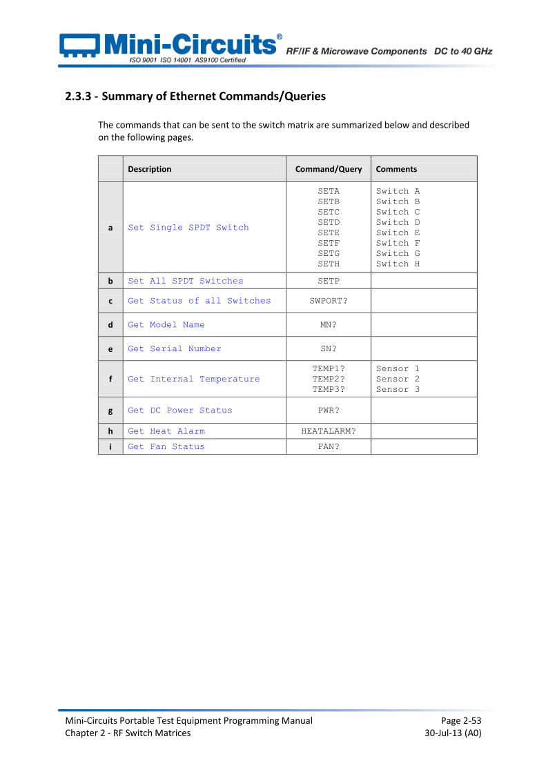
2.3.3 - Summary of Ethernet Commands/Queries
The commands that can be sent to the switch matrix are summarized below and described on the following pages.
Description Command/Query Comments
a Set Single SPDT Switch
SETA
SETB
SETC
SETD
SETE
SETF
SETG
SETH
Switch A
Switch B
Switch C
Switch D
Switch E
Switch F
Switch G
Switch H
b Set All SPDT Switches SETP
c Get Status of all Switches SWPORT?
d Get Model Name MN?
e Get Serial Number SN?
f Get Internal Temperature
TEMP1?
TEMP2?
TEMP3?
Sensor 1
Sensor 2
Sensor 3
g Get DC Power Status PWR?
h Get Heat Alarm HEATALARM?
i Get Fan Status FAN?

Mini-Circuits Portable Test Equipment Programming Manual Page 2-54 Chapter 2 - RF Switch Matrices 30-Jul-13 (A0)
2.3.4 - Detailed Description of Ethernet Commands/Queries
2.3.4 (a) - Set Single SPDT Switch
Description
This function applies to the SPDT switch matrices, it sets an individual switch within the switch matrix whilst leaving all other switches (if applicable) unchanged. The switches are designated A to H, as labeled on the front of the switch matrix (not all switches are available in all models).
Command SET[switch]=[state]
Input Parameters
Parameter Description
[switch] The individual switch (A-H) to be controlled. For example: SETA sets switch A SETB sets switch B
[state] The state (0 or 1) into which the switch should be set: 0 - Connect Com port to port 1 1 - Connect Com port to port 2
Return Values
Value Description
0 Command failed
1 Command completed successfully
2 Command failed (DC power is not connected)
HTTP Command Example
Set switch A to state 1 (Com port connected to port 2):
http://192.168.100.100/SETA=1
Set switch C to state 0 (Com port connected to port 1):
http://192.168.100.100/SETC=0
See Also
Set All SPDT Switches Get States of All SPDT Switches
Mini-Circuits Portable Test Equipment Programming Manual Page 2-55 Chapter 2 - RF Switch Matrices 30-Jul-13 (A0)
2.3.4 (b) - Set All SPDT Switches
Description
This function applies to the SPDT switch matrices, it sets all switches within the matrix simultaneously. Each switch in the matrix is represented by a single bit in a binary word so that switch A is the LSB (least significant bit) and switch H (if applicable) is the MSB (most significant bit). The decimal equivalent of the binary word is sent to set the states of all switches. Note: The bits representing switches not present in the unit have no effect on the unit. For example, USB-4SPDT-A18 contains four SPDT switches designated A (bit 0/LSB), B (bit 1), C (bit 2) and D (bit 3). Bit 4 to bit 7 (MSB) of the binary word will have no effect.
Command SETP=[states]
Input Parameters
Parameter Description
[states] Binary string of switch states represented as a decimal value. Each bit of the binary string corresponds to a single switch, with the LSB relating to switch “A”, the next bit to switch “B” (if applicable) and so on. Each bit can be set to 0 for “Com to port 1” or 1 for “Com to port 2.” For example, passing [states]=5 (binary 00000101) would set switches “A” and “C” so that Com is connected to port 2, whilst setting all other switches (if applicable) so that Com is connected to port 1.
Return Values
Value Description
0 Command failed
1 Command completed successfully
2 Command failed (DC power is not connected)
Mini-Circuits Portable Test Equipment Programming Manual Page 2-56 Chapter 2 - RF Switch Matrices 30-Jul-13 (A0)
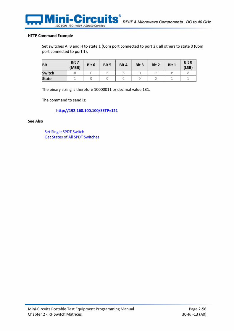
HTTP Command Example Set switches A, B and H to state 1 (Com port connected to port 2); all others to state 0 (Com port connected to port 1).
Bit Bit 7
(MSB) Bit 6 Bit 5 Bit 4 Bit 3 Bit 2 Bit 1
Bit 0 (LSB)
Switch H G F E D C B A
State 1 0 0 0 0 0 1 1
The binary string is therefore 10000011 or decimal value 131. The command to send is:
http://192.168.100.100/SETP=121
See Also
Set Single SPDT Switch Get States of All SPDT Switches
Mini-Circuits Portable Test Equipment Programming Manual Page 2-57 Chapter 2 - RF Switch Matrices 30-Jul-13 (A0)
2.3.4 (c) - Get States of All SPDT Switches
Description
This function returns the current state of all switches within the matrix. Each switch in the matrix is represented by a single bit in a binary word so that switch A is the LSB (least significant bit) and switch H (if applicable) is the MSB (most significant bit). The decimal equivalent of the binary word returned to indicate the states of all switches at once.
Command SWPORT?
Input Parameters
Parameter Description
None
Return Values
Value Description
[states] Binary string of switch states represented as a decimal value. Each bit of the binary string corresponds to a single switch, with the LSB relating to switch “A”, the next bit to switch “B” (if applicable) and so on. Each bit will be 0 for “Com to port 1” or 1 for “Com to port 2.” For example, [states]=7 (binary 00000111) would indicate that switches “A”, “B” and “C” have Com connected to port 2, whilst all other switches have Com connected to port 1.
HTTP Command Example
Return state of all switches:
http://192.168.100.100/SWPORT?
See Also
Set Single SPDT Switch Set All SPDT Switches
Mini-Circuits Portable Test Equipment Programming Manual Page 2-58 Chapter 2 - RF Switch Matrices 30-Jul-13 (A0)
2.3.4 (d) - Get Model Name
Description
This function returns model name of the connected switch matrix.
Command MN?
Input Parameters
Parameter Description
None
Return Values
Value Description
[model] The model name of the switch matrix as a string of ASCII characters (for example RC-3SPDT-A18).
HTTP Command Example
Return model name of switch matrix:
http://192.168.100.100/MN?
See Also
Get Serial Number

Mini-Circuits Portable Test Equipment Programming Manual Page 2-59 Chapter 2 - RF Switch Matrices 30-Jul-13 (A0)
2.3.4 (e) - Get Serial Number
Description
This function returns serial number of the connected switch matrix.
Command SN?
Input Parameters
Parameter Description
None
Return Values
Value Description
[serial] The serial number of the switch matrix as a string of ASCII characters (for example 11305010002).
HTTP Command Example
Return serial number of switch matrix:
http://192.168.100.100/SN?
See Also
Get Model Name

Mini-Circuits Portable Test Equipment Programming Manual Page 2-60 Chapter 2 - RF Switch Matrices 30-Jul-13 (A0)
2.3.4 (f) - Get Internal Temperature
Description
This function returns the internal temperature of the switch matrix. It does not apply to RC-1SPDT-A18 and RC-1SP4T-A18 since these models have no internal temperature sensors. RC-2SPDT-A18, RC-3SPDT-A18 and RC-4SPDT-A18 each have 2 temperature sensors which can be accessed, RC-8SPDT-A18 has 3. Note: Units with serial numbers earlier than 11108010000 may have a different number of sensors than indicated above.
Command TEMP[sensor]?
Input Parameters
Parameter Description
[sensor] The internal temperature sensor (1 to 3) to poll. For example: TEMP1? to poll sensor 1 TEMP2? to poll sensor 2 TEMP3? to poll sensor 3
Return Values
Value Description
[temp] The temperature reading of the specified internal sensor in Degrees Celsius.
HTTP Command Example
Return temperature at internal sensor 2:
http://192.168.100.100/TEMP2?
See Also
Get DC Power Status Get Heat Alarm Get Fan Status

Mini-Circuits Portable Test Equipment Programming Manual Page 2-61 Chapter 2 - RF Switch Matrices 30-Jul-13 (A0)
2.3.4 (g) - Get DC Power Status
Description
This function indicates whether the required 24V DC power supply is connected and active.
Command PWR?
Input Parameters
Parameter Description
None
Return Values
Value Description
[status] Integer value to indicate the DC power supply status: 0 – DC power supply not connected 1 – DC power supply connected
HTTP Command Example
Check DC supply connection:
http://192.168.100.100/PWR?
See Also
Get Internal Temperature Get Heat Alarm Get Fan Status
Mini-Circuits Portable Test Equipment Programming Manual Page 2-62 Chapter 2 - RF Switch Matrices 30-Jul-13 (A0)
2.3.4 (h) - Get Heat Alarm
Description
This function applies to RC-2SPDT-A18, RC-3SPDT-A18, RC-4SPDT-A18 and RC-8SPDT-A18. It returns an alarm notification if the internal temperature exceeds the factory defined limit.
Command HEATALARM?
Input Parameters
Parameter Description
None
Return Values
Value Description
[status] Integer value to indicate the heat alarm status: 0 – Device is within normal operating temperature limits 1 – Device temperature has exceeded the recommended limits
HTTP Command Example
Check heat alarm status:
http://192.168.100.100/HEATALARM?
See Also
Get Internal Temperature Get DC Power Status Get Fan Status

Mini-Circuits Portable Test Equipment Programming Manual Page 2-63 Chapter 2 - RF Switch Matrices 30-Jul-13 (A0)
2.3.4 (i) - Get Fan Status
Description
This function indicates whether the internal fan is currently operating.
Command FAN?
Input Parameters
Parameter Description
None
Return Values
Value Description
[status] Integer value to indicate the fan status: 0 – Fan is not operating 1 – Fan is currently operating
HTTP Command Example
Check fan status:
http://192.168.100.100/FAN?
See Also
Get Internal Temperature Get DC Power Status Get Heat Alarm