Embed Size (px)
Citation preview
CHAPTER 2
An engine's hot exhaust gases still have a lot of energy; harness that energy and put .it to work.
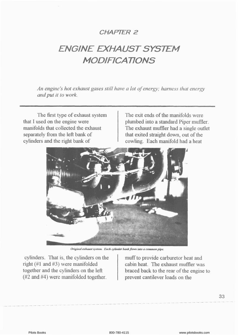
Original exhaust system Each cylinder bankflona inLn a common pipe.
The first type of exhaust system that I used on the engine were manifolds that collected the exhaust separately fiom the left bank of
The exit ends of the manifolds were plumbed into a standard Piper mufiler. The exhaust muffler had a single outlet that exited straight down, out of the
cylinders and the right bank of cowling. Each m d o l d had a heat
cylinders. That is, the cylinders on the right (#1 and #3) were manifolded together and the cylinders on the left (#2 and #4) were manifolded together.
muff to provide carburetor heat and cabin heat. The exhaust muffler was braced back to the rear of the engine to prevent cantilever loads on the
Pilots Books 800-780-4115 www.pilotsbooks.com
manifolds. I used this exhaust system on the airplane for three years. After I had worked out the initial problems with the system, it did work satisfactody. The problems consisted of the cracks in the aft ends of the manifolds and excessive heat fiom the muffler being absorbed by the gascolator. The m&ld cracks were eliminated by bracing the mufner back to the engine. The excessive gascolator heating was solved with a simple heat shield over the gascolator. Not having any previous performance data to compare with, I was satisfied with this first exhaust system. However, I did notice that at full power near sea-level elevation, the engine produced objectionable vibration, which I initially thought was caused by the Aeromatic propellor that I was using at the time. I later discovered that #4 cylinder was exhausting into the manifold through only approximately a 1 " diameter hole, causing the engine, at full sea-level power, to produce uneven power from all bcylinders, and vibrating heavily as a result. Opening up that 1 " Diameter hole to the full 1 %" inside diameter of the exhaust pipe allowed the engine to produce smooth, balanced, full-throttle power.
Since I had been a hot-rod enthusiast and had bullt and experimented with two street-rods, I knew that most exhaust systems were very inefficient and that there was probably much room for improvement in my initial aircraft exhaust system. So
began a whole series of experiments to see if I could increase my aircraft's performance by mo-g the exhaust system.
The fist experiment was to see if eliminating the back pressure caused by the mufner would help much; so, I removed the muffler, and using 90 " elbows, exhausted the gases fiom each manifold downward through the cowling. This did increase the aircraft's speed, but not as much as I had expected.
The next idea was to eliminate the drag caused by the downwards pointed exhaust plumes, by pointing the exhausts aft and maybe even benefitting some fiom the exhaust thrust. Using two more 90" elbows I jury-rigged both exhausts to point aft. This did produce an even larger speed increase. However, during the flight testing of this modrfication, the elbows .rotated and the exhausts impinged on the aluminum belly-skm of the aircraft. Now, the exhaust is about 1600 degrees Fahrenheit and aluminum melts at about 1050 degrees Fahrenheit, so it hdn't take long for the exhaust to burn through the aluminum skin, fill the cockpit with smoke fiom the burning floorboard insulation, and start giving me a real hot-foot! Fortunately, I wasn't far fiom the airport, with about 4,000 feet of altitude. So, I chopped the throttle, opened all cockpit vents and glided back to an uneventful landing at hapahoe County w o r t . The lesson I learned fiom the experience was that I
Pilots Books 800-780-4115 www.pilotsbooks.com
needed to thrnk through my planned experiments much more carefully, to recogruze the risks of test flying, and to find ways to minimize those risks.
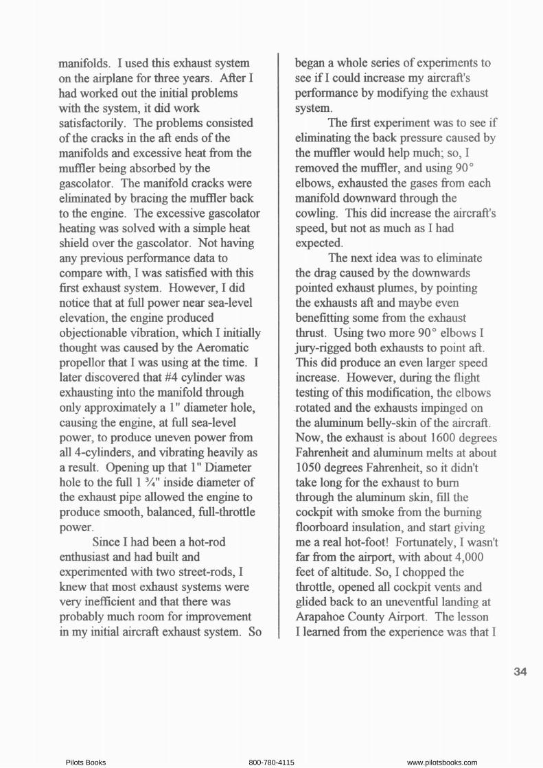
The positive results from the first two experiments served to whet my appetite for more experimentation. My next idea was to see what a separate exhaust pipe per cylinder would do. Using automotive exhaust tubing, elbows and fittings, I fabricated a set of 4 straight pipes, with only 1, less than
by others on automobile exhaust systems, discussions with people who had raced automobiles and aircraft, and reports of research done by NACA (National Advisory Committee for Aeronautics) a government agency, predecessor of NASA. Most of my more successful ideas came fiom the old NACA reports.
The next idea to try did come fiom a NACA report: constrict the end of the exhaust pipes to accelerate the
New erhausi sysLem Each cylinda har its owmpke, all& way to the end of each pipe oldCpL
90" bend, per pipe. The pipes all pointed aft, but I was careful not to let them impinge directly on the aircraft's belly slun. Flight test results fiom this latest exhaust system configuration were very encouraging.
For some time, I had been searching for ideas to try on my aircraft. Sources for ideas were: hot-rod magazines, engineering texts, research
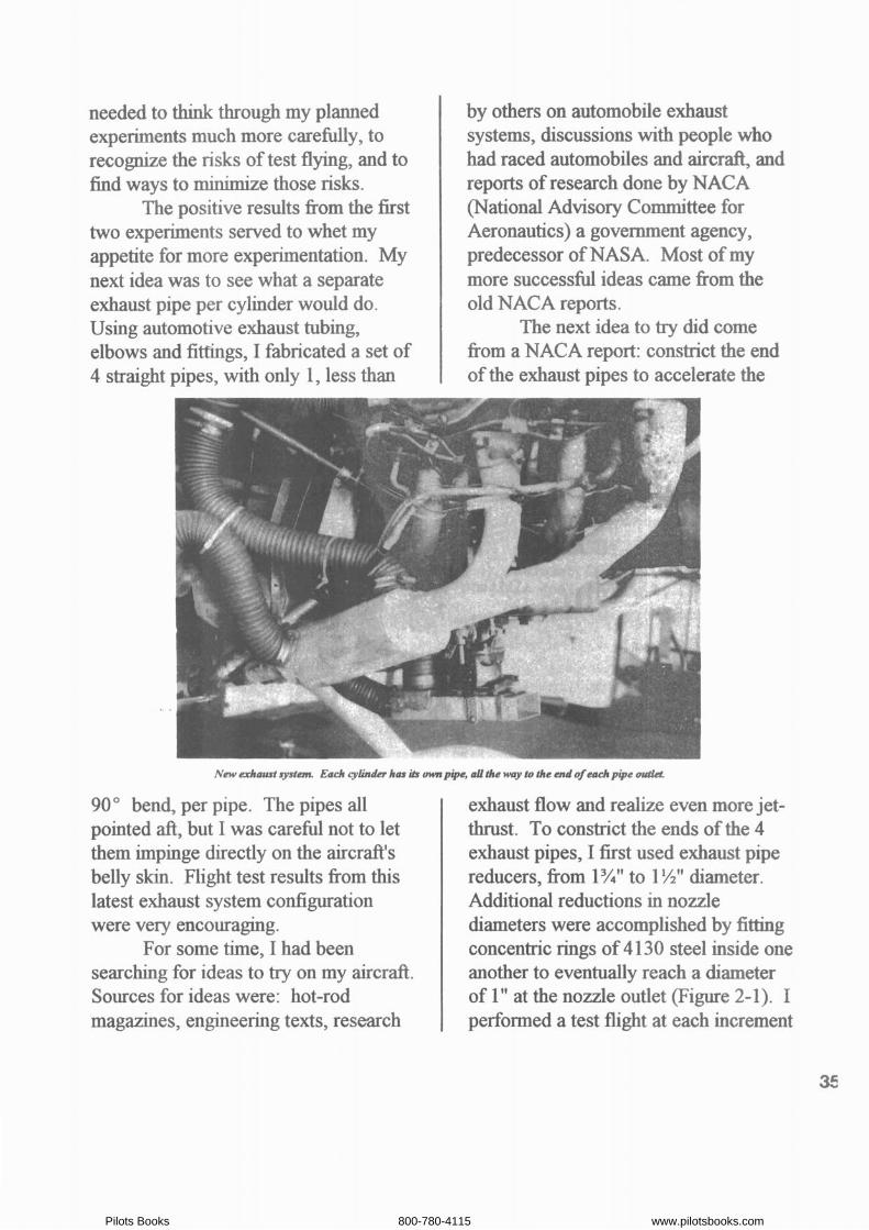
exhaust flow and realize even more jet- thrust. To constrict the ends of the 4 exhaust pipes, I first used exhaust pipe reducers, fiom 1 %" to 1 %" diameter. Additional reductions in nozzle diameters were accomplished by fitting concentric rings of 4 1 30 steel inside one another to eventually reach a dlameter of 1" at the nozzle outlet (Figure 2-1). I performed a test flight at each increment
Pilots Books 800-780-4115 www.pilotsbooks.com
I
Concentric Rings of 4130 Steel Tubing
Exhaust Pipe Reducer
FIGURE 2-Z EXHAUST JET THRUST NOZZLE
r
PARAMGTERS t - Nl Throttle
+8 -- 7000 ~ e e t Altitude Y -- +6 -- +5 --
-4 -- Diameter Nozzles
-5 -- 4 -- -7 .- -8 - - .
* 1 k 1 I 1 L
4 i5/8 lip i3/8 1 1 9 8 I
1 Nozale Diameter, Inches
FIGURE 2-2,NOZZLE D W l a E R VERSUS BENEFIT
.I
36
Pilots Books 800-780-4115 www.pilotsbooks.com
of nozzle outlet reduction, so that I would know when the trade off between increased jet thrust versus reduced horsepower due to exhaust back pressure had been optimized (Figure 2- 2). The test results indicated that the smaller the nozzle diameter, the larger the aircraft speed increase at the higher altitudes. However, the smaller nozzle diameters would also reduce the aircraft speed at lower altitudes. The obvious solution is to develop a set of variable exhaust nozzles that can be adjusted fiom the cockpit, while in flight. This I &d at a later date, which I will describe later in this chapter. Nevertheless, the speed increases fiom the fixed diameter exhaust jet nozzles were sigdicant. For my purposes, with my home airfield elevation at almost 6,000 R., I chose the nozzle diameter of 1 %I1 . This does cause a horsepower reduction at sea level, but doesn't hurt at 6,000 ft., and provides a significant speed increase at high cruise altitudes.
For some time I had been considering a cross-over exhaust system. A cross-over exhaust system manifolds together the two fiont cylinders (#1 and #2) and separately manifolds together the two rear cylinders (#3 and #4). All of the advertisements by cross-over system fabricators claimed that their system would develop more horsepower. About h s time, George Hite, a fiiend in my local EAA Chapter #301, recommended that I read a book titled "Scientific Design of Intake and
Exhaust Systems". Th~s book was written by two researchers at the University of Edinburgh, Glascow, Scotland. I learned much about the theory of automotive intake and exhaust systems fiom this book, and I consider it required reading for anyone interested in experimenting .with intake and exhaust systems. Anyway, based on the information in the book, it seemed likely that the claims of increased horsepower for the crossover exhaust system were possible. So, in due course, worlung with Dean Cochran (another fiiend in my EAA chapter), a cross-over exhaust system for my Mustang-11 was fabricated. Some modifications to Dean's standard crossover design were necessary to fit the system inside my much-streamlined and tight cowling. But Dean was patient with me and the h a 1 results were well worth the effort. Flight testing indicated a significant horsepower increase, since the same fixed-pitch propellor was now turning almost 100 RPM faster in climb and even more in top speed. And the 1 !A" diameter jet thrust nozzles worked equally well on the cross-over system. Dean Cochran also drew my attention to the subject of "exhaust anti- reversion". Specifically, a particular configuration to implement exhaust anti- reversion, that is, "anti-reversion cones." The theory of exhaust anti- reversion is to prevent hot exhaust gases fiom flowing backwards into the combustion chamber during the period
Pilots Books 800-780-4115 www.pilotsbooks.com
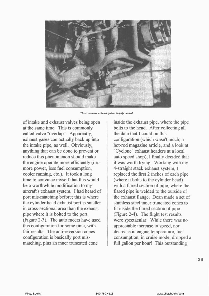
The cross-over exhaust systan is opt& named
of intake and exhaust valves being open at the same h e . This is commonly called valve "overlap". Apparently, exhaust gases can actually back up into the intake pipe, as well. Obviously, anythmg that can be done to prevent or reduce this phenomenon should make the engine operate more efficiently (i.e.- more power, less fuel consumption, cooler running, etc.). It took a long time to convince myself that this would be a worthwhde modfication to my aircraft's exhaust system. I had heard of port mis-matchmg before; this is where the cylinder head exhaust port is smaller in cross-sectional area than the exhaust pipe where it is bolted to the port (Figure 2-3). The auto racers have used this configuration for some time, with fair results. The anti-reversion cones configuration is basically port mis- matchmg, plus an inner truncated cone
inside the exhaust pipe, where the pipe bolts to the head. After collecting all the data that I could on th~s configuration (whch wasn't much; a hot-rod magazine article, and a look at "Cyclone" exhaust headers at a local auto speed shop), I finally decided that it was worth trymg. Working with my 4-straight stack ,exhaust system, I replaced the fist 2 inches of each pipe (where it bolts to the cylinder head) with a flared section of pipe, where the flared pipe is welded to the outside of the exhaust flange. Dean made a set of stainless steel inner truncated cones to fit inside the flared section of pipe (Figure 2-4). The flight test results were spectacular. Whlle there was no appreciable increase in speed, nor decrease in engine temperature, fuel consumption, in cruise mode, dropped a full gallon per hour! This outstandmg
Pilots Books 800-780-4115 www.pilotsbooks.com


![[Flip-Side] 4. Intake, Exhaust, Cylinder Flow](https://img.pdfslide.net/doc/110x75/56d6c06d1a28ab30169a58c8/flip-side-4-intake-exhaust-cylinder-flow.jpg)