Embed Size (px)
Citation preview

CHAPTER 2
SHAFT POWER CYCLES

Chapter2 Shaft Power Cycles 2
• There are two main types of power cycles;
• 1. Shaft power cycles : Marine and Land based power plants.
• 2. Aircraft propulsion cycles: Performance depends upon forward speed & altitude.

CHAPTER 2
SHAFT POWER CYCLES
I
Ideal Cycles

Chapter2 Shaft Power Cycles 4
Ideal Cycles
The analysis is based on the :
• perfection of individual components
• w , depend upon r and Tmax
w : Specific power output
: Cycle efficiency
r : Pressure ratio Tmax : Max. cycle Temperature

Chapter2 Shaft Power Cycles 5
Ideal Cycles - Assumptions
a) Compression and expansion processes are isentropic
b) The change of Kinetic Energy of the working fluid
between the inlet and outlet of each component is
negligible.
Chapter2 Shaft Power Cycles 6
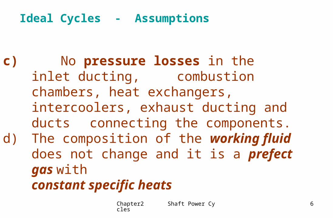
Ideal Cycles - Assumptions
c) No pressure losses in the inlet ducting, combustion chambers, heat exchangers, intercoolers, exhaust ducting and ducts connecting the components.
d) The composition of the working fluid does not change and it is a prefect gas with constant specific heats

Chapter2 Shaft Power Cycles 7
Ideal Cycles - Assumptions :
e) The mass flow rate of gas is constant
f) Heat transfer in the Heat Exchanger is complete; so in conjunction with (d)+(e), temperature rise on the cold side is equal to the temperature drop on the hot side.
• (d,e) indicates that the combustion chamber is such
that it is as if heated by an external heat source.

Chapter2 Shaft Power Cycles 8
SIMPLE Gas Turbine CYCLE• The ideal cycle for a simple Gas Turbine is the BRAYTON (or JOULE)
cycle.
• Fig. 2.1 Simple Gas Turbine

Chapter2 Shaft Power Cycles 9
SIMPLE Gas Turbine CYCLE
Steady flow energy equation:
q = hII - hI + 1/2 ( vII2 - vI
2) + w
where : q = heat transfer per unit mass flow.
w = work per unit mass flow.
w12 = - (h2 - h1) = - cp (T2 – T1)
q23 = (h3 - h2) = cp (T3 - T2)
w34 = (h3 - h4) = cp (T3 - T4)

Chapter2 Shaft Power Cycles 10
SIMPLE Gas Turbine CYCLE
The efficiency of the cycle is then :
net work outputheat supplied
C T T C T TC T T
p p
p
( ) ( )( )
3 4 2 1
3 2

Chapter2 Shaft Power Cycles 11
SIMPLE Gas Turbine CYCLE
The cycle temperatures can be related to the pressure ratio rp ;
rp = p2/p1 = p3/p4
For isentropic compression and expansion;
p/ = RT ; p/ = const.
T2/T1 = rp and T3/T4 = rp

Chapter2 Shaft Power Cycles 12
The Efficiency of the Simple Gas Turbine Cycle
)(
)/1()1(
23
212343
TTC
TTTC/TTTC
p
pp
)(
)()(
suppliedheat
outputnet work
23
1243
TTC
TTCTTC
p
pp
4312γ/1)(γ // TTTTrc p
)/11()(
)/11()11(
23
23c
TT
cT/cT

Chapter2 Shaft Power Cycles 13
The Efficiency of the Simple Gas Turbine Cycle
Then the cycle efficiency is;
where; ( 2.1 )
11 1
1 1pr c
)1
(
prc

Chapter2 Shaft Power Cycles 14
SIMPLE Gas Turbine CYCLE
The specific work output w , depends upon the size of the plant for a given power.
It is found to be a function of not only pressure ratio, but also of maximum cycle temperature T3. Thus;
w = cp (T3-T4) - cp (T2-T1)can be expressed as;
( 2.2 )
The specific work output is a function of " t " (T3/T1) and "rp" ;
w = w (t, rp).
3 ( 1) /( 1) /
1 1
11 1 1 ( 1)p
p p
w T tr c
C T T r c

Chapter2 Shaft Power Cycles 15
SIMPLE Gas Turbine CYCLE
FIG. 2.2Efficiency and specific work output - simple cycle
Fig. 2.2 Efficiency and specific work output - Simple Cycle

Chapter2 Shaft Power Cycles 16
SIMPLE Gas Turbine CYCLE
T3 : Maximum Cycle Temperature,
imposed by the metallurgical limit.
t = T3/T1 = 3.5 -4 for long life industrial plants,
t = 5-5.5 for aircraft engines with cooled turbine blades.
From the T-S diagram, it is clear that when
rp= 1 or rp = (T3/T1) w = 0
Thus in between there is a maximum (or minimum) value for w

Chapter2 Shaft Power Cycles 17
SIMPLE Gas Turbine CYCLE
For any given value of "t" (T3/T1), the optimum value of rp for maximum specific work output can be calculated by differentiating eqn. 2.2 wrt. rp ( and equating to zero.The result is;
i.e. ( 2.3 )
Since
r T Topt( )/ / 1
3 1 r topt
4312 ///)1( TTTTropt
Chapter2 Shaft Power Cycles 18
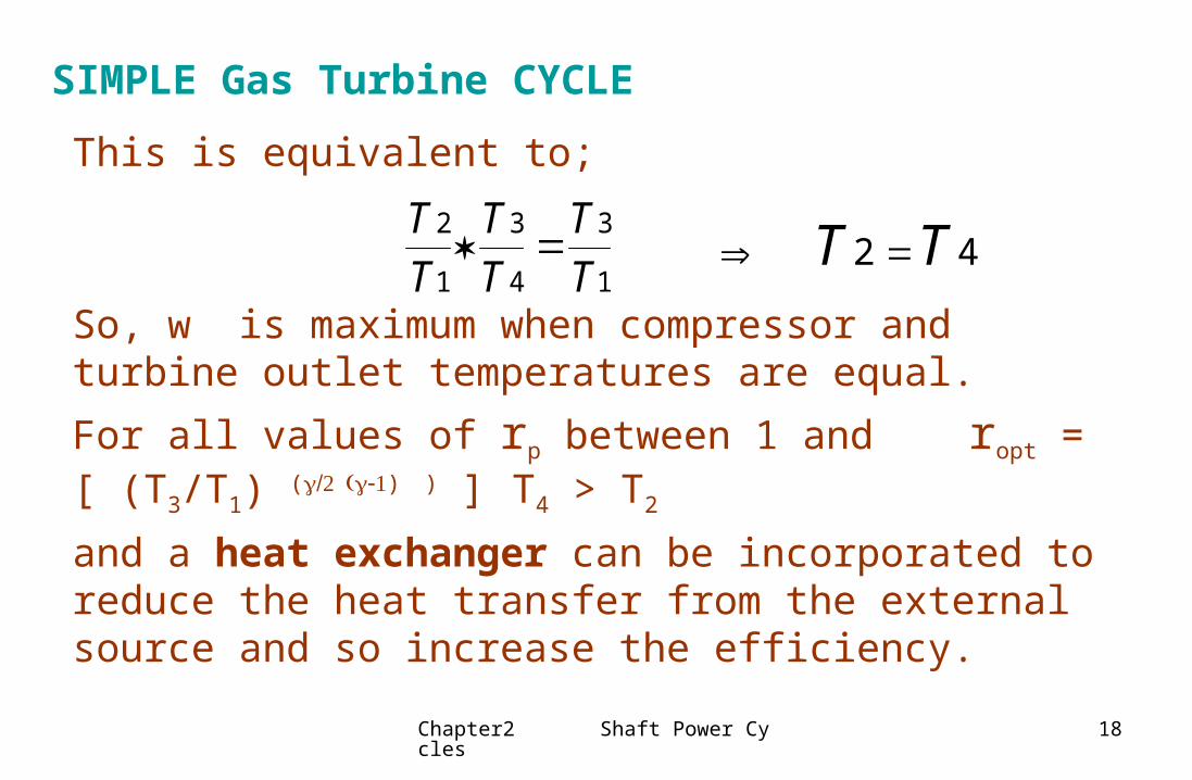
SIMPLE Gas Turbine CYCLE
This is equivalent to;
So, w is maximum when compressor and turbine outlet temperatures are equal.
For all values of rp between 1 and ropt = [ (T3/T1) () ) ]T4 > T2
and a heat exchanger can be incorporated to reduce the heat transfer from the external source and so increase the efficiency.
TT
TT
TT
2
1
3
4
3
1 T T2 4

Chapter2 Shaft Power Cycles 19
Heat Exchanger Cycle
Fig. 2.3 Simple cycle with heat - exchange

Chapter2 Shaft Power Cycles 20
Heat Exchanger Cycle
The cycle efficiency is;
with ideal HE T5 = T4
with the help of isentropic relations;
( 2.4)
C T T C T TC T T
p p
p
( ) ( )( )
3 4 2 1
3 5
1 11
3 1
rT T
ct
p( )/

Chapter2 Shaft Power Cycles 21
Heat Exchanger Cycle
Fig 2.4 Efficiency of a simple cycle with heat-exchange
for rp = 1 : = 1- 1/t which is Carnot efficiency.
as T3 increases, t increases and then increases

Chapter2 Shaft Power Cycles 22
Heat Exchanger Cycle
Specific work output does not change with HE thus is the same as the simple cycle.To obtain an appreciable improvement in by HE in ideal cycles.a) a value of rp < ropt
then work output is maximum.b) It is not necessary to use a higher cycle pressure ratio as Tmax of the cycle is increased.
(a) is true for actual cycles whereas (b) requires modification

Chapter2 Shaft Power Cycles 23
Reheat Cycle
Fig. 2.5 Reheat cycle
• A substantial increase in specific work output can be obtainedby splitting the expansion and reheating the gas between low-pressure and high-pressure turbines.

Chapter2 Shaft Power Cycles 24
Reheat Cycle
• Since the vertical distance between any pair of constant pressure lines increase with the increasing entropy
• (T3 - T4) + (T5 - T6) > (T3 - T4 )• thus : wreheat > wsimple
• w34 + w56 = Cp (T3 - T4) + Cp (T5 - T6)
• = Cp (T3 - T4) + Cp (T3 - T6)
• wt = Cp T3 (1-T4/ T3) + Cp T3 (1-T6/T5)

Chapter2 Shaft Power Cycles 25
Reheat Cycle
since
• Denoting
• then P4 = P5
TT
PP
4
3
4
3
1 ( )( )/ TT
PP
PP
6
5
6
5
1 6
4
1 ( ) ( )( )/ ( )/
1
N
4 6
3 3 41 1
T N N
p
w P P
C T P P
Chapter2 Shaft Power Cycles 26
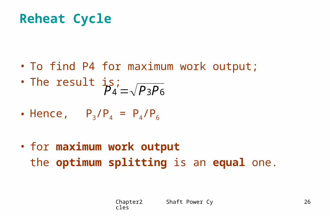
Reheat Cycle
• To find P4 for maximum work output; • The result is;
• Hence, P3/P4 = P4/P6
• for maximum work output
the optimum splitting is an equal one.
P P P4 3 6

Chapter2 Shaft Power Cycles 27
Reheat Cycle• Specific work output of the cycle is then;
w = Cp (T3 - T4) + Cp (T5 - T6) - Cp (T2- T1)
• Thus:
• ( 2.5 )
• Then the efficiency; ( 2.6)
wC T
TT
TT
TT
TT
TT
ttct
tcc
p 1
3
1
4
1
5
1
6
1
2
11
wC T
t ctcp 1
2 12
2 1 22t c t ct c t c
//

Chapter2 Shaft Power Cycles 28
Reheat Cycle• Effect of Reheat :increase in specific output and decrease in efficiency.
Fig. 2.6 Work output vs. r in a Reheat Cycle
• EXERCISE :
For a simple Reheat Cycle, prove that specific work output is maximum when rp =(T3/T1)2/3 = t2/3 .

Chapter2 Shaft Power Cycles 29
Cycle with Reheat & Heat Exchange• The reduction in efficiency due to reheat can be overcomed by adding heat
exchanger. • The high exhaust gas temperature is now fully utilized in the HE and the
increase in work output is no longer offset by the increase in heat supplied.
Fig. 2.7Reheat cycle with Heat - Exchange

Chapter2 Shaft Power Cycles 30
Fig. 2.8 Efficiency - reheat cycle with heat - exchange
Reheat cycle with Heat - Exchange

Chapter2 Shaft Power Cycles 31
Cycle With Reheat & Heat Exchange
The reduction in efficiency due to reheat can be overcomed by adding a heat exchanger.
The higher exhaust gas temperature is now fully utilized in the HE and the increase in work output is no longer offset by the increase in heat supplied.
6
3 42
1
5
6
7HE
f
f

Chapter2 Shaft Power Cycles 32
Cycle With Reheat & Heat Exchange
1
2
7
3 5
4 6
8
HE
T
s

Chapter2 Shaft Power Cycles 33
Cycle With Reheat, Intercooling & Heat Exchange
3
42 5
67
HE
f
f
1 8
10
9
LPC HPC LPT HPT
Intercooler

Chapter2 Shaft Power Cycles 34
Cycle With Reheat, Intercooling & Heat Exchange
1
2
7
3
5
4
6 8
HE
T
s
9
10

CHAPTER 2
SHAFT POWER CYCLES
II
Actual Cycles

Chapter2 Shaft Power Cycles 36
ACTUAL CYCLES
• The performance of real cycles differ from that of ideal
cycles for the following reasons :
a) Change in Kinetic Energy between inlet and outlet of each
component can not necessarily be ignored.• b) Compression and expansion are actually irreversible and
therefore involves an increase in entropy• c) Fluid friction causes pressure losses in components and
associated ducts.• d) HE can not be ideal, terminal temperature difference is
inevitable

Chapter2 Shaft Power Cycles 37
ACTUAL CYCLES
• e) Slightly more work than that required for the compression process will be necessary to overcome bearing and windage friction in the transmission between compressor and turbine and to drive ancillary components such as fuel and oil pumps. (mech)
• f) Cp and changes throughout the cycle.
Cp = f(T) h= f(T) and chemical composition.
• g) Combustion is not complete (comb)

Chapter2 Shaft Power Cycles 38
• The efficiency of any machine (which absorbs or produces work), is normally expressed in terms of the ratio of actual to ideal work transfers
• For a compressor;
• For a perfect gas;
h = Cp T ,
• This relation is sufficiently accurate for real gasses under conditions encountered in a GT if a mean Cp over the relevant range of temperature is used
o ideal
c
o actual
w h h
w h h
ACTUAL CYCLES

Chapter2 Shaft Power Cycles 39
Compressor and Turbine Efficiencies
• Then for compressors;
( 2.7 )
• Similarly for turbines the isentropic efficiency defined as;
( 2.8 )
02 01
02 01
c
T T
T T
03 04
03 04t
w T T
w T T

Chapter2 Shaft Power Cycles 40
ACTUAL CYCLES
• For compressors: from equation 2.7
( 2.9 )
• Similarly for turbines;
( 2.10 )03 04 03
03 04
( 1) /1( ) [1 ( ) ]
/tT T TP P
01 02
02 01
01
( 1) /( ) ( ) 1c
T PT T
P

Chapter2 Shaft Power Cycles 41
Compressor & Turbine Efficiencies
• Since
• Thus ( 2.11 )
• Since the vertical distance between a pair of constant pressure lines on the T-S diagram increases as entropy increases,
Ts’ > T’ s > c ( for compressors )
c
TT
ss
c
T
T
s

Chapter2 Shaft Power Cycles 42
Compressor and Turbine Efficiencies
• Now consider an axial flow compressor consisting of a number of successive stages.
• If the blade design is similar in successive blade rows it is reasonable to assume that the isentropic efficiency of a single stage s remains the same through the compressor.
• Then the overall temperature rise;

Chapter2 Shaft Power Cycles 43
Compressor and Turbine Efficiencies• The difference between c and s will increase with the number of stages i.e. with the increase of pressure ratio.
• A physical explanation is that the increase in temperature due to friction in one stage results in more work being required in the next stage.
• A similar argument can be
used to show that for a turbine
t > st .
Fig. 2.9 Definition of Isentropic
and Small Stage Efficiencies

Chapter2 Shaft Power Cycles 44
Polytropic Efficiency
• Isentropic efficiency of an elemental stage in the process such that it is constant throughout the whole process.
• For a compression process η c = dT'/dT = const.
• But for an isentropic process,
• in differential form
dT'= η c dT
• integrating between 1 & 2 (inlet & outlet)
( 2.12 )
( 1) // .T p const
dTT
dpp
1
2 1
2 1
( 1) ln( )
ln( )c
P P
T T

Chapter2 Shaft Power Cycles 45
Polytropic Efficiency
• So c can be computed from measured values of P and T at the
inlet an outlet of the compressor, as;
( 2.13 )
• Finally the relation between c & c ;
( 2.14 )
2 2
1 1
( 1) /( )( ) c
T P
T P
2 1 2 1
2 1 2 1
( 1) /
( 1) /
/ 1 ( / ) 1
/ 1 ( / ) 1c c
T T P P
T T P P

Chapter2 Shaft Power Cycles 46
Polytropic Efficiency
• Similar relations can be obtained for turbines since ,
• It can be shown that for an expansion between turbine inlet 3 and outlet 4;
( 2.15 )
( 2.16 )
t
dT
dT
3 3
4 4
( 1) /( ) tT P
T P
3 4
3 4
( 1) /
( 1) /
11 ( )
/1
1 ( )/
t
t
P P
P P

Chapter2 Shaft Power Cycles 47
Polytropic Efficiency
Fig. 2.10 Variation of turbine and compressor isentropic efficiency with pressure ratio for polytropic efficiency of 85 %

Chapter2 Shaft Power Cycles 48
Polytropic Efficiency• In practice, as with c and t , it is normal to define the polytropic
efficiencies in terms of stagnation temperatures and pressures.
( 2.17 )
• where
( 2.18 )
where
• Here n is the coefficient for a polytropic process.
02
02 01 01
01
( 1) /[( ) 1]n nPT T T
P
1 1
c
n
n
03 04 03
03 04
( 1) /1[1 ( ) ]
/n nT T T
P P
1 1t
n
n

Chapter2 Shaft Power Cycles 49
Pressure Losses
Fig. 2.11 Pressure losses
• Pb = Pressure loss in Combustion Chamber
• Pha = Frictional pressure loss on the air side of HE
• Phg = Frictional pressure loss on the gas side of HE

Chapter2 Shaft Power Cycles 50
Pressure Losses
• Pressure losses cause a decrease in the available turbine pressure ratio.
• Po3 = Po2 - Pb - Pha
• Po4 = Pa + Phg
• It is better to take Phg & Pb as fixed proportions of compressor delivery pressure; Then;
03 02
02 02
1 b haP P
P PP P

Chapter2 Shaft Power Cycles 51
HEAT EXCHANGER EFFECTIVENESS
• Turbine exhaust gasses reject heat at the rate of:
mt Cp46 (T04-T06)
• Compressor delivery receives heat at a rate of:
mc Cp25 (T05-T02)
• If mc = mt
Then Cp46 (T04-T06) = Cp25 (T05-T02)

Chapter2 Shaft Power Cycles 52
HEAT EXCHANGER EFFECTIVENESS
• One possible measure of performance is the ratio of the actual energy received by the cold air to the maximum possible value. Thus;
• HE effectiveness = Cp25 (T05-T02) / Cp24 (T04-T02)
• over the mean temperature ranges if Cp25 = Cp24
HE effectiveness = ( T05-T02) /(T04-T02)
• Most generally :
HE effectiveness = mcCp25( T05-T02) / mtCp24(T04-T02)

Chapter2 Shaft Power Cycles 53
MECHANICAL LOSSES
• In all Gas Turbines, the power necessary to drive the compressor is direct,
so any loss that occurs is due to bearing friction and windage ;• this amounts to about 1 %
• If the transmission efficiency is m, then
• wct = Cp12 (T02-T01)/m ( m = 99 % )
• Any power used to drive auxillary components
such as fuel and oil pumps, gearing losses are ussually accounted for by subtracting from the net output.

Chapter2 Shaft Power Cycles 54
Variation of Specific Heat
Cp/ Cv = Cp - Cv = R
Cp = R/( -1 ) = R /( - 1 )M
for air Cpa = 1.005 kJ/kg K , a =1.4
for combustion gasses Cpg = 1.148 kJ/kgK ,
g =1.333
Rair = 0.287 kJ/kg-K
Cp changes with T, but the change with p is negligible

Chapter2 Shaft Power Cycles 55
Fuel/Air Ratio, Combustion Efficiency and Cycle Efficiency
• Combustion problem in GT is to calculate the Fuel/Air (F/A) ratio = "f" required to transform unit mass of air at T02 and f kg of fuel at the fuel temperature Tf to ( 1 + f ) kg of products at T03 .
• Since the process is adiabatic, the energy equation is simply;
• where mi = mass of product i per unit mass of air
hi = its specific enthalpy
03 02( ) ( ) 0i fi amh h fh
03 02( ) ( ) 0i fi amh h fh

Chapter2 Shaft Power Cycles 56
Fuel/Air Ratio, Combustion Efficiency and Cycle Efficiency
• Making use of the enthalpy of reaction unit mass of fuel at a reference temperature of 25oC H25 = - ( net calorific value) = Qnet,p ; the equation can be expanded as
Cpg = Specific heat of products over the temperature range 298K T03
H25 = Enthalpy of reaction (lower heating value)a negative quantity = [-43100 kJ/kg]
03 25 02(1 ) ( 298) (298 ) (298 ) 0
fpg pa pff C T f H C T fC T

Chapter2 Shaft Power Cycles 57
Fuel/Air Ratio, Combustion Efficiency and Cycle Efficiency
• Therefore, for a given fuel and the values of T02 & T03 ; "f" can be calculated.
• A chart is given in the book to determine the "f" for a given combustion temperature rise (T03-T02) for various T02 's.
• A convenient method of allowing for combustion losses is to introduce a combustion efficiency defined by
b
theoretical f for given T
actual f for a given T

Chapter2 Shaft Power Cycles 58
Fuel/Air Ratio, Combustion Efficiency and Cycle Efficiency
• For an air mass flow ma ; total fuel consumption is
f*ma.
• The specific fuel consumption;
[ kg/kW-h ]
• wN = specific net work output in kW/( kg/s ) of air flow
3600. . 3600.
.a
a N N
f m fsfc
m w w

Chapter2 Shaft Power Cycles 59
Fuel/Air Ratio, Combustion Efficiency and Cycle Efficiency
• Then the cycle efficiency is
• where Qnet,p = net calorific value = -H25
, ,
. 3600
. .a N
f net p net p
m w
m Q sfcQ

CHAPTER 2
SHAFT POWER CYCLES
III
Comparative Performance of Practical Cycles

Chapter2 Shaft Power Cycles 61
1. Simple GT Cycle
Fig. 2.12 Cycle efficiency and specific output of simple gas turbine
With component losses : h (T03, rp) for each cycle max. temperature T03, h has a peak value at a paticular rp.

Chapter2 Shaft Power Cycles 62
1. Simple GT Cycle
• Optimum press ratio for maximum efficiency differs from that for maximum specific work output.
• But (rp) is quite flat around the peak so. the lowest rp which will give an accepted performance is chosen.
• As T03 increases higher rp is advantageous
• As T03 increases η increases. Therefore component losses compared to net work output gets less important.
• As T03 increases ws increases appreciably. This is important for aircaft GT since SIZE of GT is smaller for a given power.
• *Increasing Ta ; wnet and efficiency both decreases.


Chapter2 Shaft Power Cycles 64
2.Heat Exchange Cycle
Fig. 2.13 Heat - exchange cycle• HE slightly reduces ws due to additional pressure losses.
But effects (increases) and reduces the optimum press ratio for max.

Chapter2 Shaft Power Cycles 65

Chapter2 Shaft Power Cycles 66
3.Heat Exchange Cycle with Reheat or Intercooling
Fig. 2.15 Cycle with Heat-Exchange and Reheat

Chapter2 Shaft Power Cycles 67
3.Heat Exchange Cycle with Reheat or Intercooling
• With HE, addition of REHEAT improves the specific work output considerably without loss of efficiency.
• The gain in efficiency due to Reheat obtained with the ideal cycle is not realized in practice
• * partly because of the additional pressure loss in the reheat chamber and the inefficiency of the expansion process,
• * but primarily because the effectiveness of the HE quite low and the additional energy in the exhaust gas is not wholly recovered.

Chapter2 Shaft Power Cycles 68
3.Heat Exchange Cycle with Reheat or Intercooling
• Reheat has not been widely used in practice because the additional "CC" and the associated control problems
• Can off-set the advantage gained from the decrease in size of the main components consequent upon the increase in specific output.
• Intercooling, although increases specific output and cycle efficiency; intercoolers tend to be bulky and if they require cooling water, the self contained nature of the GT is lost.
• In practice most GT utilize either a higher pressure ratio simple cycle or a low pressure ratio HE cycle.
• The other additions to the cycles mentioned do not nominally show sufficient advantage to offset the increased complexity and capital cost.

Chapter2 Shaft Power Cycles 69
Cogas Cycles and Cogeneration Schemes
• In the exhaust gases from a GT there is still an ample amount of energy. This energy could be utlized.
• The only limitation is the exhaust temperature (Stack Temp.) should not be reduced much below 170oC to avoid dewpoint corrosion problems due to the sulphur content of the fuel.
• The exhaust heat could be used in various ways.
• It could be wholly, used to produce steam in a waste heat boiler for a steam turbine to angment the shaft power produced, it is called as COGAS-"Combined Gas/Steam Cycle Power, "plant

Chapter2 Shaft Power Cycles 70
Cogas Cycles and Cogeneration Schemes
• Alternatively the exhaust heat maybe used to produce hot water or steam for same chemical process, for district or factory heating, for a distillation plant,
(for and absorption refrigerator in water chilling or air conditioning plant).
The shaft power there will normally be used to produce electricity
• This system is refered to as a
COGENERATION or TOTAL ENERGY PLANT.

Chapter2 Shaft Power Cycles 71
Cogas Cycles
Fig.2.15 T-H diagrams for single and dual pressure COGAS schemes

Chapter2 Shaft Power Cycles 72
Cogas Cycles
• For any given T03 of GT rc increases T04 (exhaust) decreases. Thus the heat available to the steam cycle decreases.
h gas (fall in boiler) = h (rise between feedwater inlet and
steam outlet)
Tterminal ≥ 20°C & Tpinchpt ≥20°C
if the boiler is to be of economic size.

Chapter2 Shaft Power Cycles 73
Cogas Cycles• A reduction in T4;
Psteam decrease that can be used for steam cycle.
• In the combined plant, therefore, selection of a higher compressor pressure ratio to improve the gas turbine efficiency may lead to a fall in steam cycle efficiency and no net gain in overall thermal efficiency.
• In practice, however, a higher pressure ratio is accompanied by a higher turbine inlet temperature and the most advanced combined cycles use high pressure ratio gas turbines.

Chapter2 Shaft Power Cycles 74
Cogas Cycles
• Most COGAS plants are produced by adding a suitable exhaust heated Rankine Cycle conditions which matches best to GasTurbine.
• COGAS plants for large base load generating stations overall is not the ultimate citerion.
• The cost of electricity sold is ultimate and this also depends on the capital cost of the plant.
• Due to the abundancy of choices it is very difficult to optimize these cycles. These have efficiencies 43-50 %

Chapter2 Shaft Power Cycles 75
Cogeneration Plant
Fig. 2.16 Cogeneration plant • This one is suitable for applications in which the required ratio of heat
output to electrical output might vary over a wide range.

Chapter2 Shaft Power Cycles 76
Cogeneration Plant
• When only power required,then waste heat boiler is completely bypassed.
• When max. heat/power ratio is required the HE is bypassed and supplemantary fuel is burnt in the boiler.
• The overall efficiency may be defined as
= [( net work + useful heat output ) / unit air mass flow ] / [ f.Qnet,p ]
• Useful heat output per unit air mass flow isCp [ Tin - 443 ]
• For high values of Q/HP rc has little effect on
• rc choosen to give wmax ,hence minimum capital cost.
• Heat exchanger useful for small Q/Power ratios.


![2.B Power Cycles with Two-Phase Media (Vapor Power Cycles) · 2B-1 2.B Power Cycles with Two-Phase Media (Vapor Power Cycles) [SB&VW – Chapter 3, Chapter 11, Sections 11.1 to 11.7]](https://img.pdfslide.net/doc/110x75/5c2e0f0d09d3f2dd0b8c2597/2b-power-cycles-with-two-phase-media-vapor-power-cycles-2b-1-2b-power-cycles.jpg)