Embed Size (px)
Citation preview
Copyright © 2004 by John Wiley & Sons, Inc. All rights reserved.
Chapter 2: Wireless IP Network Architectures
Jyh-Cheng Chen and Tao Zhang
IP-Based Next-Generation Wireless Networks Published by John Wiley & Sons, Inc. January 2004

Copyright © 2004 by John Wiley & Sons, Inc. All rights reserved. 2
This material is protected under all Copyright Laws as they currently exist. ©2004 Jyh-Cheng Chen and Tao Zhang, and John Wiley & Sons, Inc. All rights reserved. Notwithstanding user’s ability to use and modify the PowerPoint Slides, it is understood that the original version of these slides, as well as any and all modifications thereof, and all corresponding copyrights, shall at all times remain the property of Jyh-Cheng Chen and Tao Zhang, and John Wiley & Sons, Inc.
Copyright © 2004 by John Wiley & Sons, Inc. All rights reserved. 3
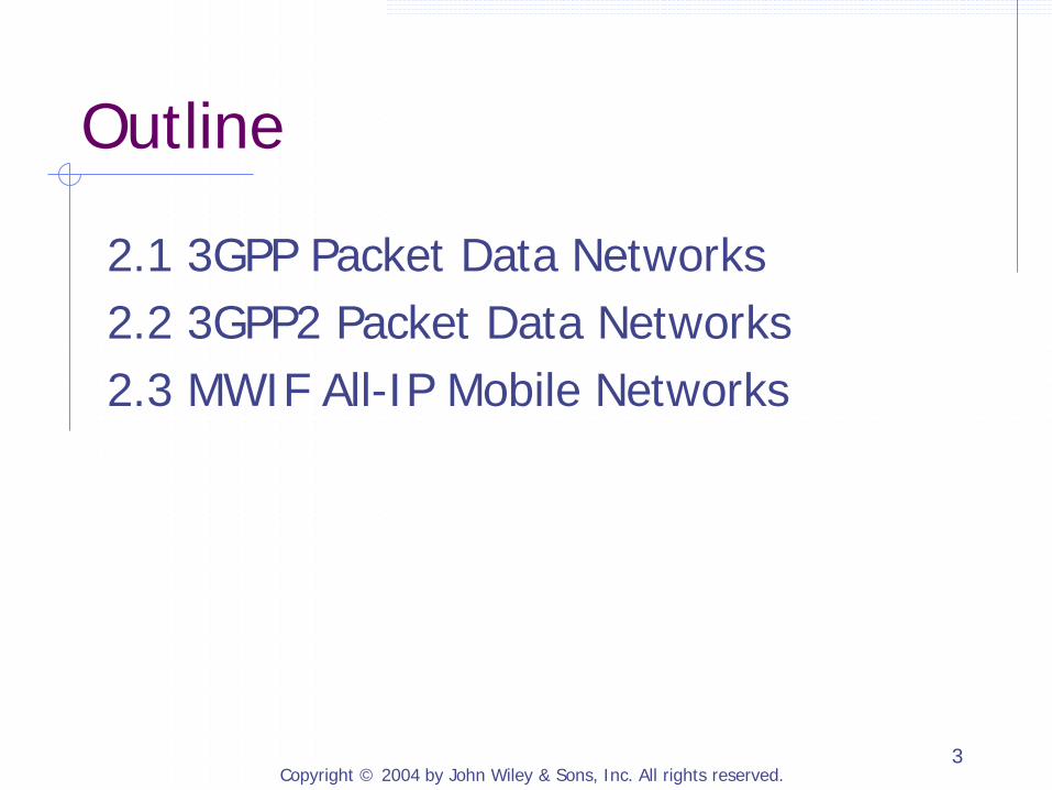
Outline
2.1 3GPP Packet Data Networks 2.2 3GPP2 Packet Data Networks 2.3 MWIF All-IP Mobile Networks
Copyright © 2004 by John Wiley & Sons, Inc. All rights reserved. 4
2.1 3GPP Packet Data Networks
2.1.1 Network Architecture 2.1.2 Protocol Reference Model 2.1.3 Packet Data Protocols, Bearers, and Connections for Packet Services 2.1.4 Packet Data Protocol (PDP) Context 2.1.5 Steps for a Mobile to Access 3GPP Packet-Switched Services 2.1.6 User Packet Routing and Transport 2.1.7 Configuring PDP Addresses on Mobile Stations 2.1.8 GPRS Attach Procedure 2.1.9 PDP Context Activation and Modification 2.1.10 Radio Access Bearer Assignment 2.1.11 Packet-Switched Domain Protocol Stacks 2.1.12 Accessing IP Networks through PS Domain
Copyright © 2004 by John Wiley & Sons, Inc. All rights reserved. 5
2.1.1 Network Architecture
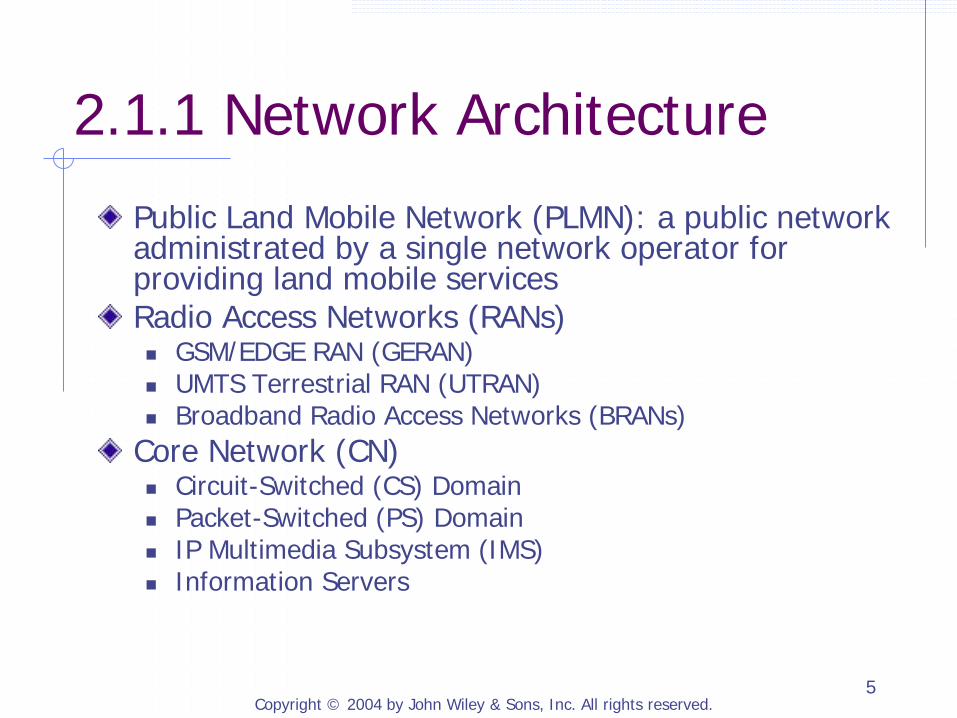
Public Land Mobile Network (PLMN): a public network administrated by a single network operator for providing land mobile services Radio Access Networks (RANs) GSM/EDGE RAN (GERAN) UMTS Terrestrial RAN (UTRAN) Broadband Radio Access Networks (BRANs)
Core Network (CN) Circuit-Switched (CS) Domain Packet-Switched (PS) Domain IP Multimedia Subsystem (IMS) Information Servers
Copyright © 2004 by John Wiley & Sons, Inc. All rights reserved. 6
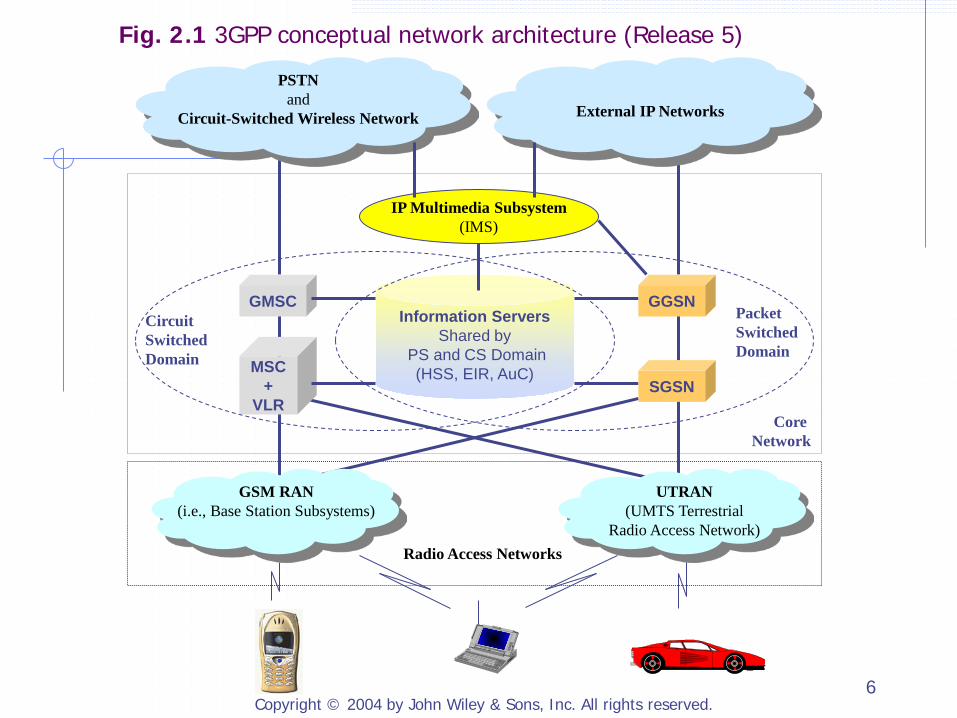
Circuit Switched Domain
Packet Switched Domain
Core Network
Radio Access Networks
GGSN
SGSN
GMSC
MSC +
VLR
Information Servers Shared by
PS and CS Domain (HSS, EIR, AuC)
IP Multimedia Subsystem (IMS)
External IP Networks
PSTN and
Circuit-Switched Wireless Network
GSM RAN (i.e., Base Station Subsystems)
UTRAN (UMTS Terrestrial
Radio Access Network)
Fig. 2.1 3GPP conceptual network architecture (Release 5)
Copyright © 2004 by John Wiley & Sons, Inc. All rights reserved. 7
GERAN and UTRAN
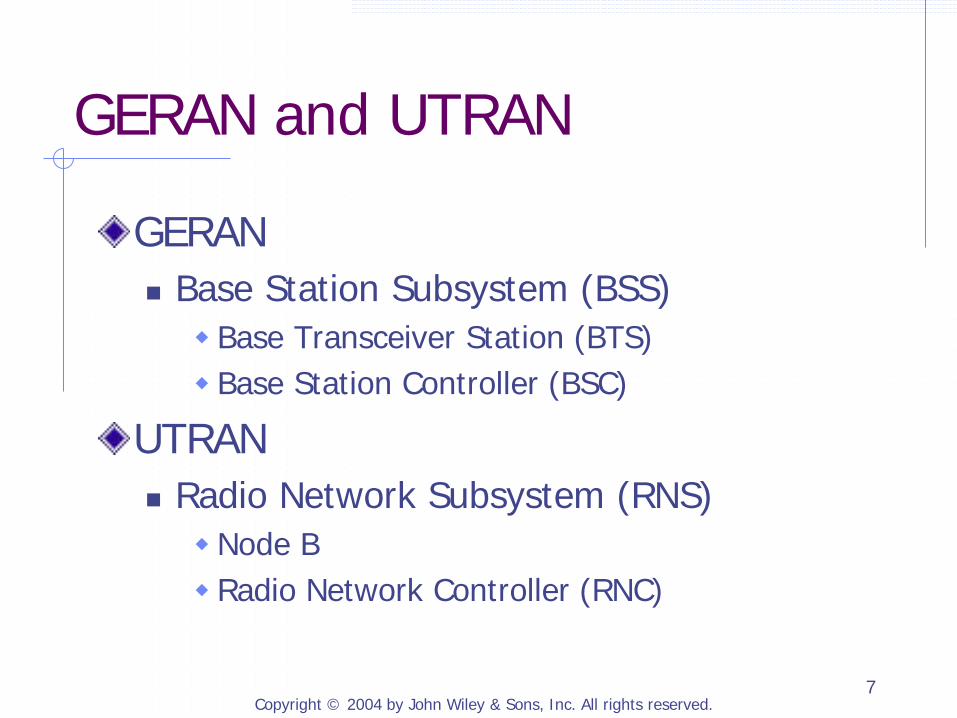
GERAN Base Station Subsystem (BSS) Base Transceiver Station (BTS) Base Station Controller (BSC)
UTRAN Radio Network Subsystem (RNS) Node B Radio Network Controller (RNC)

Copyright © 2004 by John Wiley & Sons, Inc. All rights reserved. 8
2.1.1.1 Mobile Devices, Subscribers, and Their Identifiers
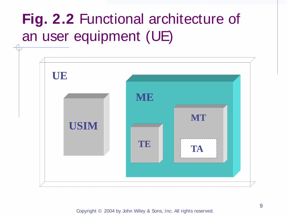
Mobile Station (MS): in GSM User Equipment (UE): in UMTS Mobile Equipment (ME) Terminal Equipment (TE) Mobile Termination (MT)
Terminal Adapter (TA)
UMTS Subscriber Identity Module (USIM)
Copyright © 2004 by John Wiley & Sons, Inc. All rights reserved. 9
USIM TE
MT
TA
ME
UE
Fig. 2.2 Functional architecture of an user equipment (UE)
Copyright © 2004 by John Wiley & Sons, Inc. All rights reserved. 10
Identifiers
International Mobile Station Equipment Identity (IMEI): identify MT manufacturer, country, type International Mobile Subscriber Identity (IMSI): globally unique and permanently assigned for each subscriber stored on USIM
Copyright © 2004 by John Wiley & Sons, Inc. All rights reserved. 11
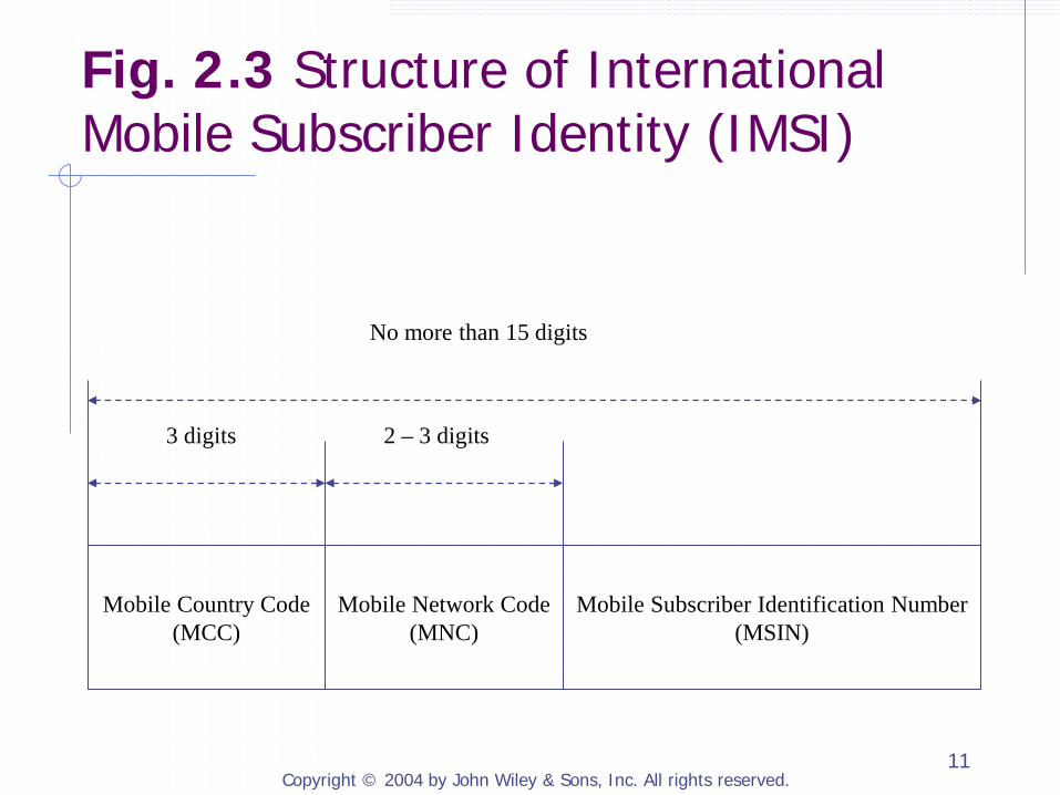
Mobile Country Code (MCC)
Mobile Network Code (MNC)
Mobile Subscriber Identification Number (MSIN)
3 digits 2 – 3 digits
No more than 15 digits
Fig. 2.3 Structure of International Mobile Subscriber Identity (IMSI)
Copyright © 2004 by John Wiley & Sons, Inc. All rights reserved. 12
Identifiers (Cont.)
Temporary Mobile Subscriber Identity (TMSI) 4-octet number assigned to a mobile temporarily
by a MSC/VLR or by a SGSN P-TMSI mapping between TMSI and IMSI: only known by
mobile and network
IP address single or multiple may acquire an IP address only when necessary
Copyright © 2004 by John Wiley & Sons, Inc. All rights reserved. 13
2.1.1.2 Circuit-Switched Domain in Core Network
Mobile-services Switching Center (MSC) Gateway MSC (GMSC) Visitor Location Register (VLR) Home Subscriber Server (HSS), Equipment Identity Register (EIR), and Authentication Center (AuC)
Copyright © 2004 by John Wiley & Sons, Inc. All rights reserved. 14
Switching vs. Call Control
MSC Server: call control and mobility management CS Media Gateway (CS-MGW): circuit switching, media conversion, payload processing (e.g., echo canceller, codec), payload transport
Copyright © 2004 by John Wiley & Sons, Inc. All rights reserved. 15
2.1.1.3 Packet-Switched Domain in the Core Network
Network access control: registration, authentication and authorization, admission control, message filtering, usage data collection Packet routing and transport: route user packets toward their destinations Mobility management: tracking the locations of mobile terminals, initiating paging, maintaining up-to-date routes
Copyright © 2004 by John Wiley & Sons, Inc. All rights reserved. 16
Serving GPRS Support Node (SGSN)
Access control Location management: track the locations of mobiles; may report the location information to the HLR Route management: maintain and relay user traffic between the mobile and the GGSN Paging: initiating paging to idle mobiles Interface with service control platforms: contact point with CAMEL (Customized Applications for Mobile Enhanced Logic)
Copyright © 2004 by John Wiley & Sons, Inc. All rights reserved. 17
Gateway GPRS Support Node (GGSN)
Packet routing and forwarding center: all user packets to and from a mobile in a PLMN will be sent first to a GGSN (refer to as the mobile’s serving GGSN) Route and mobility management: maintain a route to the SGSN that is currently serving a mobile and uses the route to exchange the user traffic with the SGSN
Copyright © 2004 by John Wiley & Sons, Inc. All rights reserved. 18
Identifiers of SGSN and GGSN
IP address may be private IP address
SGSN Number and GGSN Number used primarily with non-IP protocols, e.g.,
MAP or other SS7-based protocols
Copyright © 2004 by John Wiley & Sons, Inc. All rights reserved. 19
2.1.1.4 IP Multimedia Subsystem
Release 5 introduced the IP Multimedia Subsystem (IMS) Support real-time voice and multimedia IP services Use the Session Initiation Protocol (SIP) for signaling and session control for all real-time multimedia services Will be discussed in Chapter 3

Copyright © 2004 by John Wiley & Sons, Inc. All rights reserved. 20
2.1.1.5 Information Servers
Shared by CS and PS domains Home Subscriber Server (HSS) master logical database maintain user subscription information to control network
services Home Location Registrar (HLR): main component of HSS
which maintains users’ identities, locations, and service subscription information
Authentication Center (AuC) maintain information to authenticate each user and to
encrypt the communication accessed by the HSS
Equipment Identity Register (EIR) maintain IMEIs of the subscribers
Copyright © 2004 by John Wiley & Sons, Inc. All rights reserved. 21
2.1.2 Protocol Reference Model
RAN Internal Interfaces RAN-to-CN Interfaces CS CN Internal Interfaces many interfaces use MAP protocol
PS CN Internal Interfaces
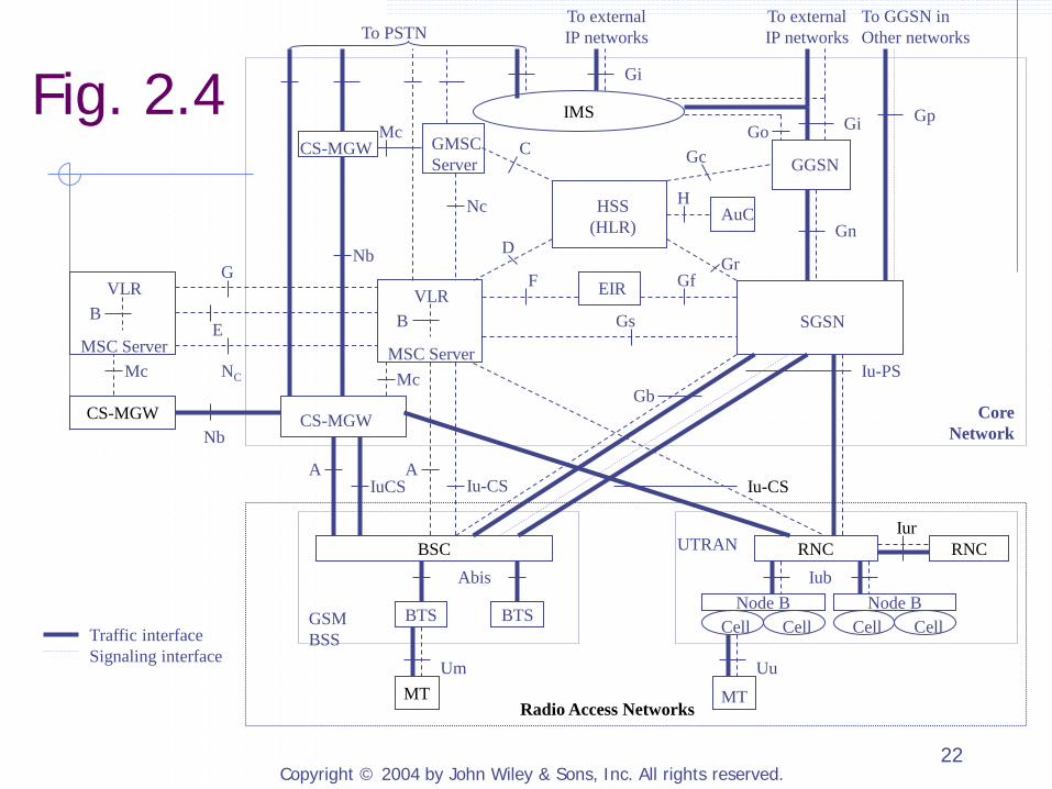
Copyright © 2004 by John Wiley & Sons, Inc. All rights reserved. 22
Core Network
SGSN
MSC Server
VLR B
HSS (HLR)
GGSN
IMS
CS-MGW
BSC
BTS BTS
Abis
GSM BSS
MT Um
RNC Iub
UTRAN
Uu
Node B Cell Cell
Node B Cell Cell
MT
Mc
Gs
Iu-PS Gb
Iu-CS A A
IuCS
MSC Server
VLR B
CS-MGW
Mc
G
E
NC
Nb
EIR
AuC
F Gf
GMSC Server
CS-MGW
Nb
Gi Go
To external IP networks To PSTN
Gp
Gi
Traffic interface Signaling interface
Nc
Mc
Gn
C Gc
D Gr
H
To GGSN in Other networks
To external IP networks
Radio Access Networks
Iu-CS
RNC Iur
Fig. 2.4
Copyright © 2004 by John Wiley & Sons, Inc. All rights reserved. 23
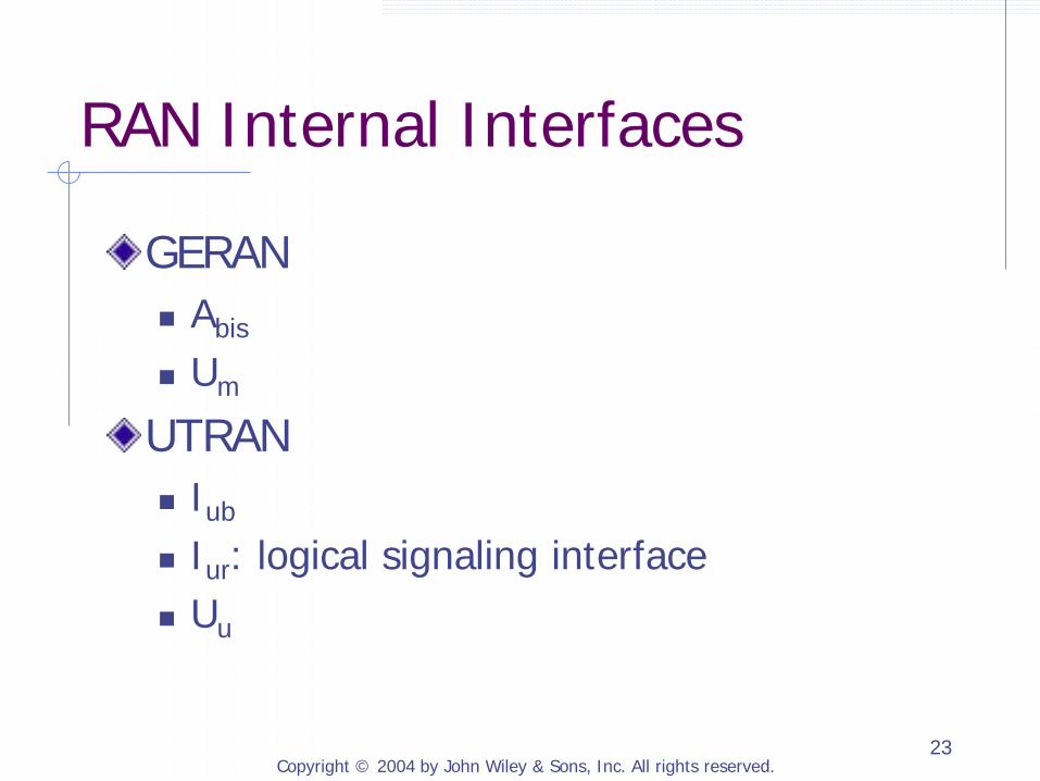
RAN Internal Interfaces
GERAN Abis
Um
UTRAN Iub
Iur: logical signaling interface Uu
Copyright © 2004 by John Wiley & Sons, Inc. All rights reserved. 24
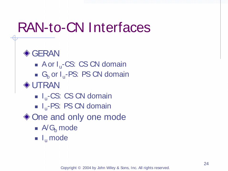
RAN-to-CN Interfaces
GERAN A or Iu-CS: CS CN domain Gb or Iu-PS: PS CN domain
UTRAN Iu-CS: CS CN domain Iu-PS: PS CN domain
One and only one mode A/Gb mode
Iu mode
Copyright © 2004 by John Wiley & Sons, Inc. All rights reserved. 25
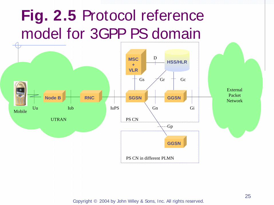
Uu Iub IuPS Gn Gi
UTRAN PS CN
Gs Gc
D
Gr
Gp
PS CN in different PLMN
SGSN GGSN RNC Node B
MSC +
VLR
HSS/HLR
GGSN
Mobile
External Packet
Network
Fig. 2.5 Protocol reference model for 3GPP PS domain
Copyright © 2004 by John Wiley & Sons, Inc. All rights reserved. 26
2.1.3 Packet Data Protocols, Bearers, and Connections for Packet Services
Packet Data Protocol (PDP): used to exchange user packets over a 3GPP PS CN domain Packet Data Unit (PDU): user packet transported inside a 3GPP network over traffic bearer Traffic bearer: a set of network resources and data transport functions used to deliver user traffic between two network entities
Copyright © 2004 by John Wiley & Sons, Inc. All rights reserved. 27
Mobile RNC SGSN GGSN
3GPP Bearer
Radio Access Bearer (RAB)
Lower Layer
Bearers
Iu Gn
CN Bearer
Radio Bearer
Lower Layer
Bearers
Iu Bearer
Lower Layer
Bearers
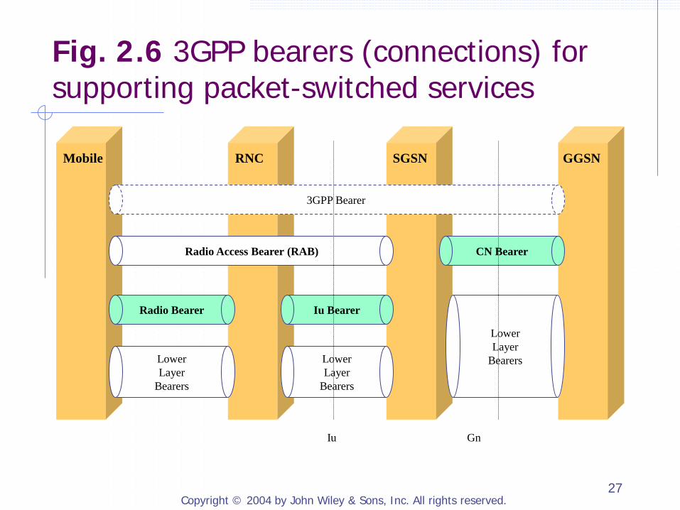
Fig. 2.6 3GPP bearers (connections) for supporting packet-switched services
Copyright © 2004 by John Wiley & Sons, Inc. All rights reserved. 28
Separation of Bearers
The (Traffic) Radio Bearers, Iu (Traffic) Bearers, Radio Access Bearers, and CN Bearers are managed by different protocols and procedures. allows different protocols and procedures
to be used; evolve with less dependency on each other
facilitates mobility management
Copyright © 2004 by John Wiley & Sons, Inc. All rights reserved. 29
Signaling Radio Bearer
Traffic Radio Bearer
Iu Signaling Bearer
Iu Traffic Bearer
Mobile-SGSN Signaling Connection
Radio Access Bearer (RAB)
RRC Connection RANAP Connection
Mobile RNC SGSN
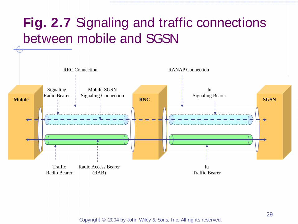
Fig. 2.7 Signaling and traffic connections between mobile and SGSN
Copyright © 2004 by John Wiley & Sons, Inc. All rights reserved. 30
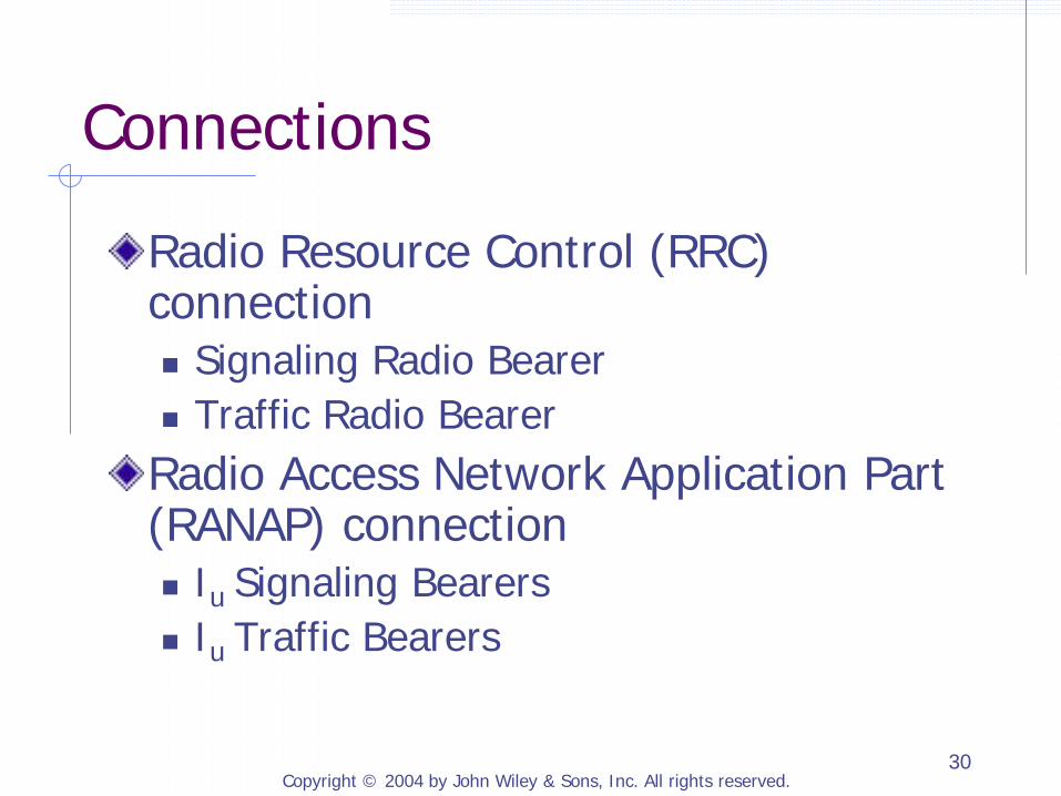
Connections
Radio Resource Control (RRC) connection Signaling Radio Bearer Traffic Radio Bearer Radio Access Network Application Part (RANAP) connection Iu Signaling Bearers Iu Traffic Bearers

Copyright © 2004 by John Wiley & Sons, Inc. All rights reserved. 31
2.1.4 Packet Data Protocol (PDP) Context
A set of information that the network uses to determine how to forward user packets destined to and originated from a particular PDP address Contain the following main information PDP Address Routing Information: identifiers of tunnels and
Access Point Name (APN) Quality of Service (QoS) Profiles: QoS Profile
Subscribed, QoS Profile Requested, QoS Profile Negotiated
Copyright © 2004 by John Wiley & Sons, Inc. All rights reserved. 32
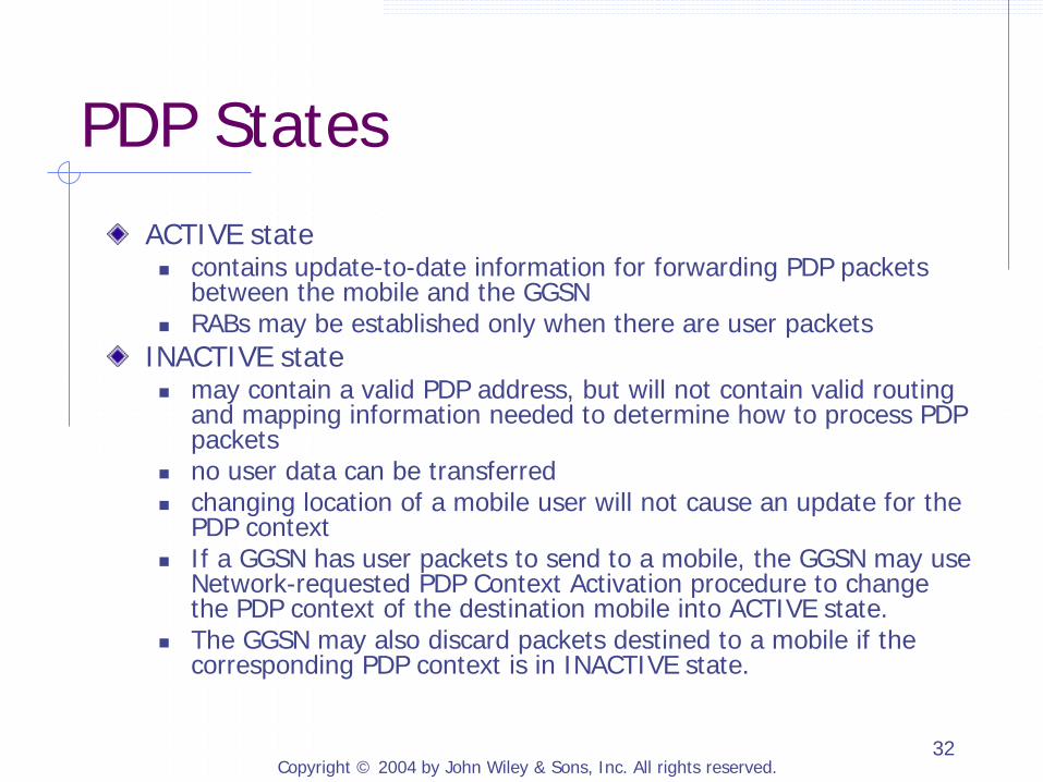
PDP States ACTIVE state contains update-to-date information for forwarding PDP packets
between the mobile and the GGSN RABs may be established only when there are user packets
INACTIVE state may contain a valid PDP address, but will not contain valid routing
and mapping information needed to determine how to process PDP packets
no user data can be transferred changing location of a mobile user will not cause an update for the
PDP context If a GGSN has user packets to send to a mobile, the GGSN may use
Network-requested PDP Context Activation procedure to change the PDP context of the destination mobile into ACTIVE state.
The GGSN may also discard packets destined to a mobile if the corresponding PDP context is in INACTIVE state.
Copyright © 2004 by John Wiley & Sons, Inc. All rights reserved. 33
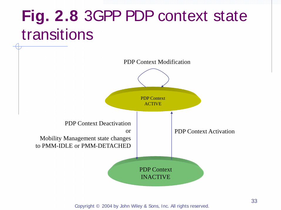
PDP Context ACTIVE
PDP Context INACTIVE
PDP Context Activation PDP Context Deactivation
or Mobility Management state changes
to PMM-IDLE or PMM-DETACHED
PDP Context Modification
Fig. 2.8 3GPP PDP context state transitions
Copyright © 2004 by John Wiley & Sons, Inc. All rights reserved. 34
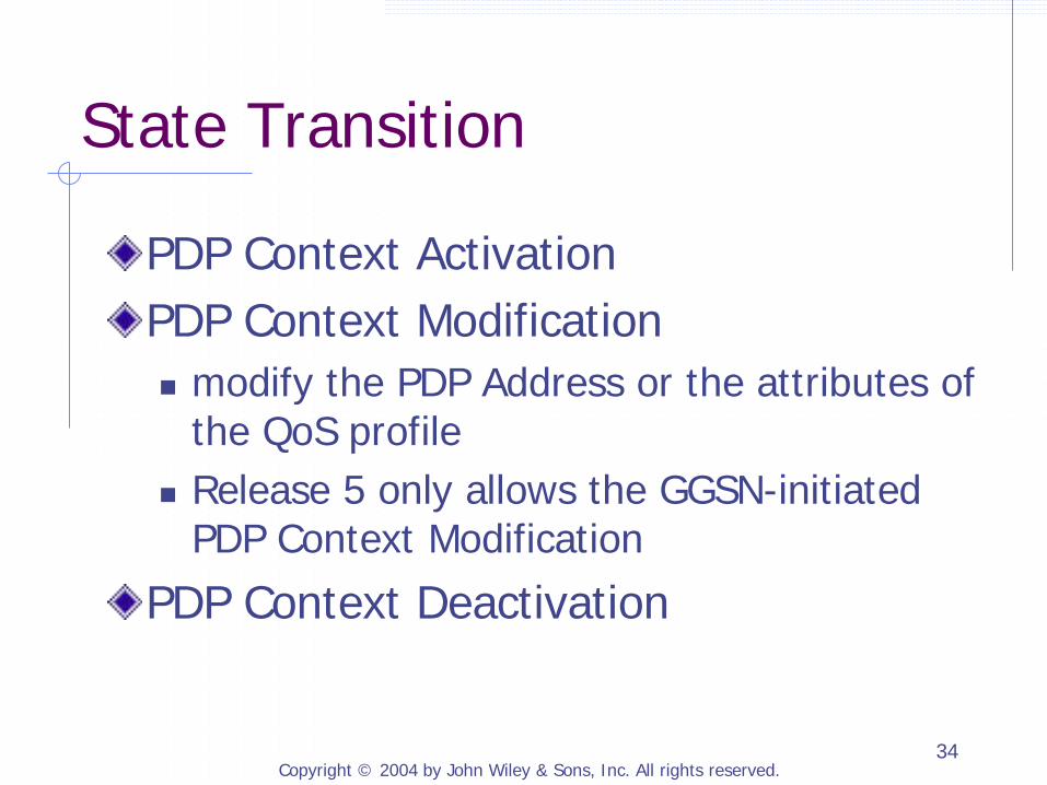
State Transition
PDP Context Activation PDP Context Modification modify the PDP Address or the attributes of
the QoS profile Release 5 only allows the GGSN-initiated
PDP Context Modification
PDP Context Deactivation
Copyright © 2004 by John Wiley & Sons, Inc. All rights reserved. 35
2.1.5 Steps for a Mobile to Access 3GPP Packet-Switched Services
GPRS Attach PDP Context Activation and RAB Establishment Register with the IMS
Copyright © 2004 by John Wiley & Sons, Inc. All rights reserved. 36
SGSN
Mobile
GPRS Attach
GGSN SGSN
Mobile
2. PDP Context Activation
1. Activate PDP Context Request
3. Establish Radio Access Bearer
4. Activate PDP Context Accept
Mobile
IMS Registration with IMS SGSN GGSN
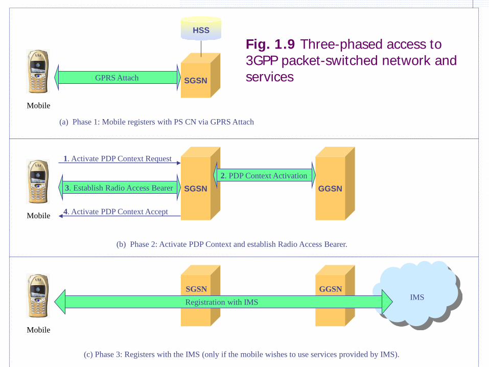
(a) Phase 1: Mobile registers with PS CN via GPRS Attach
(b) Phase 2: Activate PDP Context and establish Radio Access Bearer.
(c) Phase 3: Registers with the IMS (only if the mobile wishes to use services provided by IMS).
HSS
Fig. 1.9 Three-phased access to 3GPP packet-switched network and services

Copyright © 2004 by John Wiley & Sons, Inc. All rights reserved. 37
GPRS Attach A mobile registers with SGSN. A mobile provides its identity and service requirements to the SGSN and will be authenticated and authorized by the SGSN. Establish a Mobility Management Context on the mobile, in the RAN, and on the SGSN. This allows the RAN and the SGSN to track the mobile’s location. Establish a signaling connection between the mobile and the SGSN. The mobile and the SGSN use this signaling connection to exchange signaling and control messages needed to perform the GPRS Attach procedure. Allow the mobile to access some services provided by the SGSN. Such services include sending and receiving SMS messages and being paged by the SGSN.
Copyright © 2004 by John Wiley & Sons, Inc. All rights reserved. 38
PDP Context Activation and RAB Establishment
A mobile can request the network to establish and activate a PDP Context for its PDP address after the mobile has performed GPRS Attach successfully. A successful PDP context activation will trigger the PS CN domain to establish the CN Bearer and the RAB. A mobile will be able to send and receive user packets over the PS CN domain.
Copyright © 2004 by John Wiley & Sons, Inc. All rights reserved. 39
Register with the IMS
When a mobile wishes to use the IP-based real-time voice or multimedia services provided by the IMS, the mobile needs to perform registration with the IMS. SIP registration procedure is used for a user to register with the IMS. Will be described in detail in Chapter 3

Copyright © 2004 by John Wiley & Sons, Inc. All rights reserved. 40
2.1.6 User Packet Routing and Transport
Inside the PS CN domain, IP is the main protocol for transporting user packets between network nods. IP is used for routing between GGSNs. Routing of user packets between SGSN and GGSN is based on GPRS-specific protocols and procedures.

Copyright © 2004 by John Wiley & Sons, Inc. All rights reserved. 41
Packet Routing
GGSN acts as a central point for routing of all user packets. User packets are tunneled between RNC and SGSN, between SGSN and GGSN, and between two SGSNs. GPRS Tunneling Protocol (GTP): routing and mobility
management Host-specific routes are used to forward user packets between a mobile and a GGSN. maintain an individual routing entry as part of a PDP context
for every mobile terminal that has an active PDP context
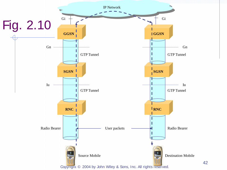
Copyright © 2004 by John Wiley & Sons, Inc. All rights reserved. 42
GTP Tunnel
GTP Tunnel
GTP Tunnel
GTP Tunnel
User packets
Gi Gi
Gn
Iu
Gn
Iu
Radio Bearer Radio Bearer
GGSN
SGSN
RNC
GGSN
SGSN
RNC
IP Network
Source Mobile Destination Mobile
Fig. 2.10
Copyright © 2004 by John Wiley & Sons, Inc. All rights reserved. 43
Mapping between Identifiers
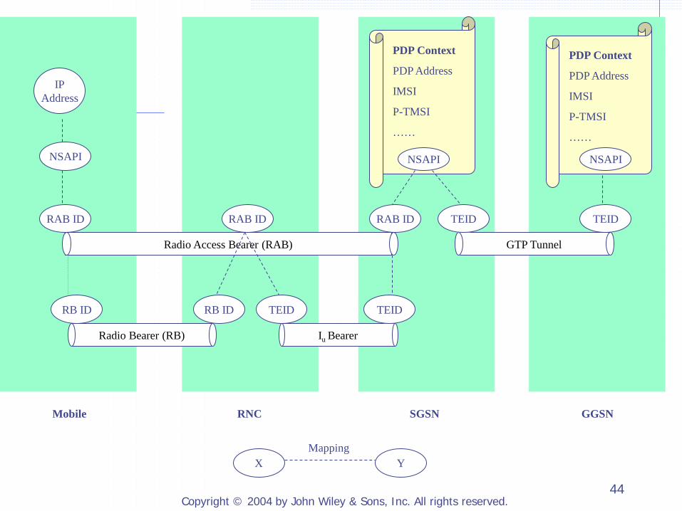
Packets addressed to the PDP address are delivered by the lower protocol to the IP layer through the Service Access Point. identified by a Network-layer Service Access Point
Identifier (NSAPI) a unique NAPSI is used for each IP address
Tunnel Endpoint Identifier (TEID) exchanged during tunnel setup process
Radio Access Bearer Identifier (RAB ID) Radio Bearer Identifier (RB ID)
Copyright © 2004 by John Wiley & Sons, Inc. All rights reserved. 44
TEID
TEID RB ID RB ID
GTP Tunnel
TEID
Radio Bearer (RB) Iu Bearer
TEID
RAB ID RAB ID RAB ID
Radio Access Bearer (RAB)
Mobile RNC SGSN GGSN
IP Address
NSAPI
X Y Mapping
PDP Context
PDP Address
IMSI
P-TMSI
……
NSAPI
PDP Context
PDP Address
IMSI
P-TMSI
……
NSAPI
Copyright © 2004 by John Wiley & Sons, Inc. All rights reserved. 45
2.1.7 Configuring PDP Addresses on Mobile Stations
Use a static PDP address assigned by the visited 3GPP network Use a static PDP address assigned by an external IP network Acquire a PDP address dynamically from the visited 3GPP network Acquire a PDP address dynamically from an external IP network

Copyright © 2004 by John Wiley & Sons, Inc. All rights reserved. 46
Dynamic PDP Address from an External IP Network
The visited PS domain first activates a PDP context without a PDP address for the mobile. The visited PS CN will not forward other user packets to or from the mobile before a valid PDP address is added to the mobile’s PDP context. The mobile’s serving GGSN in the visited network will have to learn the PDP address assigned to the mobile.
Copyright © 2004 by John Wiley & Sons, Inc. All rights reserved. 47
2.1.8 GPRS Attach Procedure
GPRS Attach procedure to attach to the PS domain IMSI Attach procedure to attach to the CS domain May combine GPRS Attach procedure and IMSI Attach procedure to attach to the PS and the CS domain simultaneously

Copyright © 2004 by John Wiley & Sons, Inc. All rights reserved. 48
MS New SGSN Old SGSN EIR GGSN HLR
Attach Request
Identification Request
Identification Response
Identity Response
Update Location
Cancel Location
Cancel Location ACK
Insert Subscriber Data
Insert Subscriber Data ACK
Update Location ACK Attach Accept
Attach Complete
Delete PDP Context Request
Delete PDP Context Response
Authentication and Authorization
IMEI verification
Identity Request
Authentication and Authorization
IMEI Verification
Fig. 2.12
Copyright © 2004 by John Wiley & Sons, Inc. All rights reserved. 49
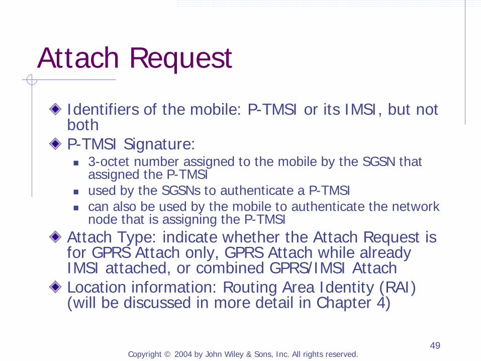
Attach Request
Identifiers of the mobile: P-TMSI or its IMSI, but not both P-TMSI Signature: 3-octet number assigned to the mobile by the SGSN that
assigned the P-TMSI used by the SGSNs to authenticate a P-TMSI can also be used by the mobile to authenticate the network
node that is assigning the P-TMSI Attach Type: indicate whether the Attach Request is for GPRS Attach only, GPRS Attach while already IMSI attached, or combined GPRS/IMSI Attach Location information: Routing Area Identity (RAI) (will be discussed in more detail in Chapter 4)
Copyright © 2004 by John Wiley & Sons, Inc. All rights reserved. 50
2.1.9 PDP Context Activation and Modification
PDP Address allocation: The network allocates an PDP address to the mobile if needed. CN Bearer Establishment: The network creates and activates the PDP context on GGSN and SGSN and establishes all the necessary bearers between SGSN and GGSN for transporting user and signaling traffic for the activated PDP context. RAB Assignment: The network establishes the Radio Access Bearers to carry user traffic.

Copyright © 2004 by John Wiley & Sons, Inc. All rights reserved. 51
2.1.9 PDP Context Activation and Modification (Cont.)
2.1.9.1 Mobile-Initiated PDP Context Activation and Modification 2.1.9.2 Network-Requested PDP Context Activation 2.1.9.3 PDP Context Modification
Copyright © 2004 by John Wiley & Sons, Inc. All rights reserved. 52
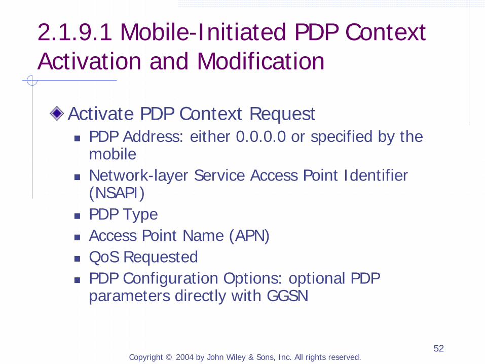
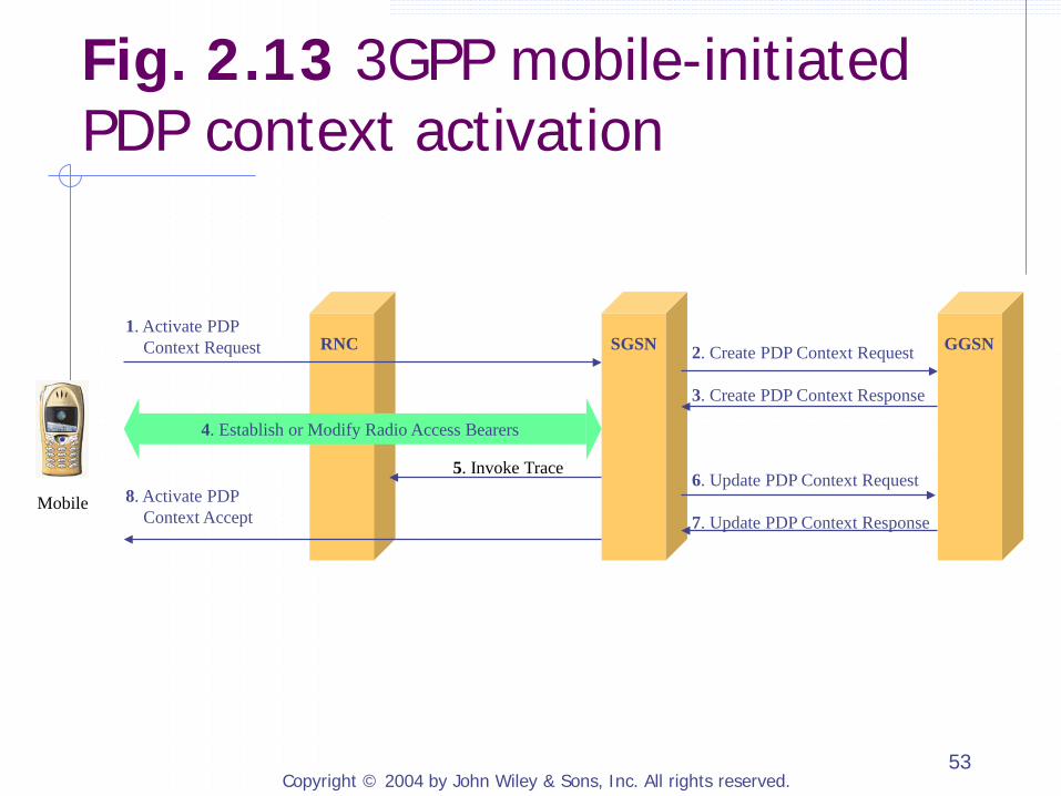
2.1.9.1 Mobile-Initiated PDP Context Activation and Modification
Activate PDP Context Request PDP Address: either 0.0.0.0 or specified by the
mobile Network-layer Service Access Point Identifier
(NSAPI) PDP Type Access Point Name (APN) QoS Requested PDP Configuration Options: optional PDP
parameters directly with GGSN
Copyright © 2004 by John Wiley & Sons, Inc. All rights reserved. 53
5. Invoke Trace
Mobile
2. Create PDP Context Request 3. Create PDP Context Response 6. Update PDP Context Request 7. Update PDP Context Response
1. Activate PDP Context Request
8. Activate PDP Context Accept
4. Establish or Modify Radio Access Bearers
RNC SGSN GGSN
Fig. 2.13 3GPP mobile-initiated PDP context activation
Copyright © 2004 by John Wiley & Sons, Inc. All rights reserved. 54
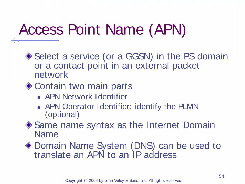
Access Point Name (APN)
Select a service (or a GGSN) in the PS domain or a contact point in an external packet network Contain two main parts APN Network Identifier APN Operator Identifier: identify the PLMN
(optional) Same name syntax as the Internet Domain Name Domain Name System (DNS) can be used to translate an APN to an IP address
Copyright © 2004 by John Wiley & Sons, Inc. All rights reserved. 55
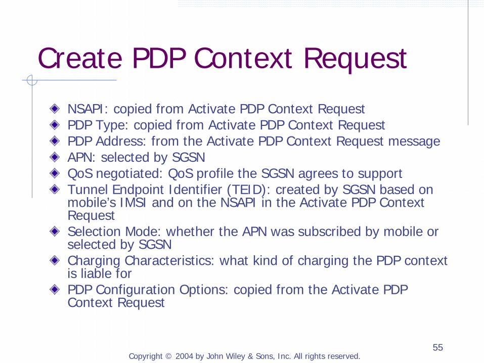
Create PDP Context Request NSAPI: copied from Activate PDP Context Request PDP Type: copied from Activate PDP Context Request PDP Address: from the Activate PDP Context Request message APN: selected by SGSN QoS negotiated: QoS profile the SGSN agrees to support Tunnel Endpoint Identifier (TEID): created by SGSN based on mobile’s IMSI and on the NSAPI in the Activate PDP Context Request Selection Mode: whether the APN was subscribed by mobile or selected by SGSN Charging Characteristics: what kind of charging the PDP context is liable for PDP Configuration Options: copied from the Activate PDP Context Request
Copyright © 2004 by John Wiley & Sons, Inc. All rights reserved. 56
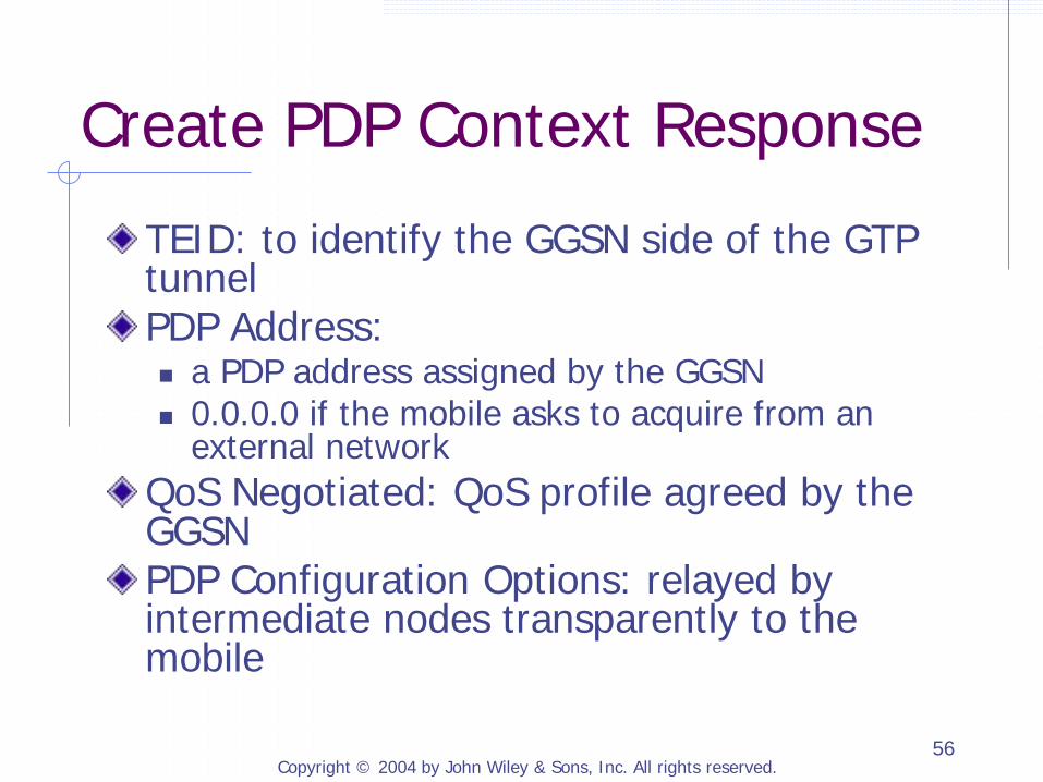
Create PDP Context Response
TEID: to identify the GGSN side of the GTP tunnel PDP Address: a PDP address assigned by the GGSN 0.0.0.0 if the mobile asks to acquire from an
external network QoS Negotiated: QoS profile agreed by the GGSN PDP Configuration Options: relayed by intermediate nodes transparently to the mobile
Copyright © 2004 by John Wiley & Sons, Inc. All rights reserved. 57
2.1.9.2 Network-Requested PDP Context Activation
GGSN must have static information about the PDP address For example, the GGSN needs to know the
mobile’s IMSI in order to query the HLR A Request PDP Context Activation message to the mobile to instruct the mobile to start the Mobile-initiated PDP Context Activation procedure described in Figure 2.13
Copyright © 2004 by John Wiley & Sons, Inc. All rights reserved. 58
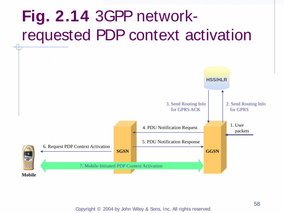
3. Send Routing Info 2. Send Routing Info for GPRS ACK for GPRS
1. User packets
4. PDU Notification Request
5. PDU Notification Response 6. Request PDP Context Activation
HSS/HLR
7. Mobile-Initiated PDP Context Activation
Mobile
SGSN GGSN
Fig. 2.14 3GPP network-requested PDP context activation

Copyright © 2004 by John Wiley & Sons, Inc. All rights reserved. 59
2.1.9.3 PDP Context Modification
Active PDP context can be modified PDP address: only a GGSN can initiate the process to modify the PDP address in an active PDP context QoS profiles: can be initiated by the mobile, GGSN, SGSN, or the RAN
Copyright © 2004 by John Wiley & Sons, Inc. All rights reserved. 60
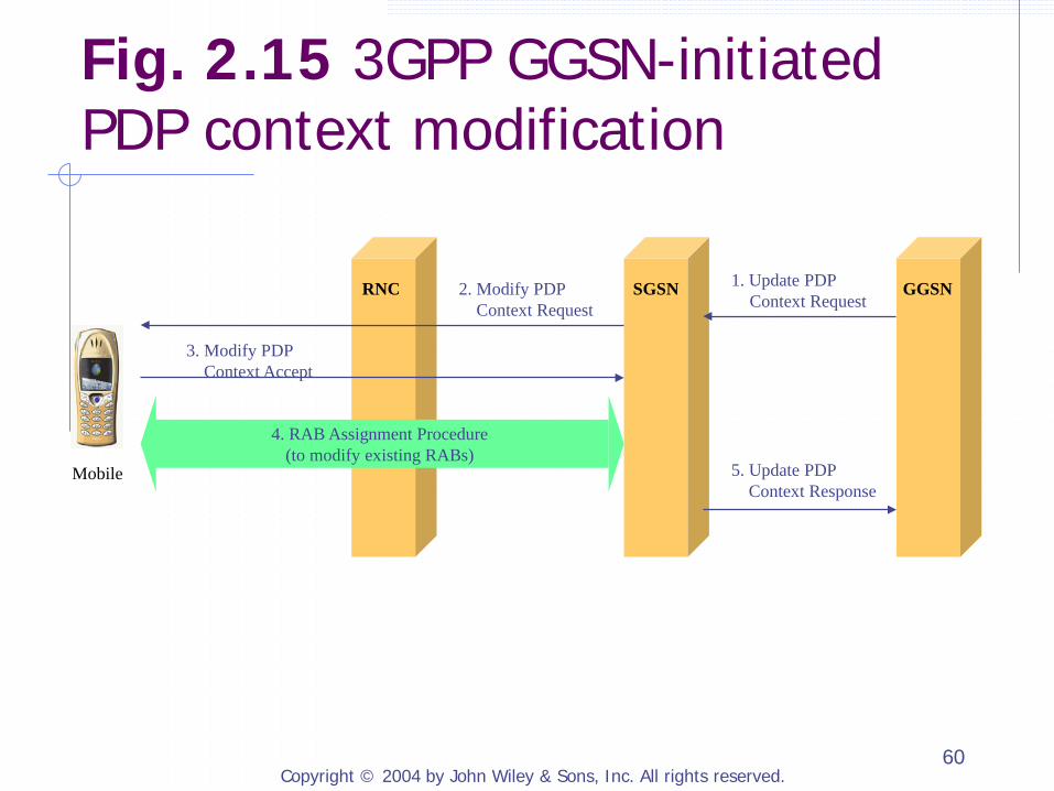
2. Modify PDP Context Request
4. RAB Assignment Procedure (to modify existing RABs)
1. Update PDP Context Request
5. Update PDP Context Response
3. Modify PDP Context Accept
RNC SGSN GGSN
Mobile
Fig. 2.15 3GPP GGSN-initiated PDP context modification
Copyright © 2004 by John Wiley & Sons, Inc. All rights reserved. 61
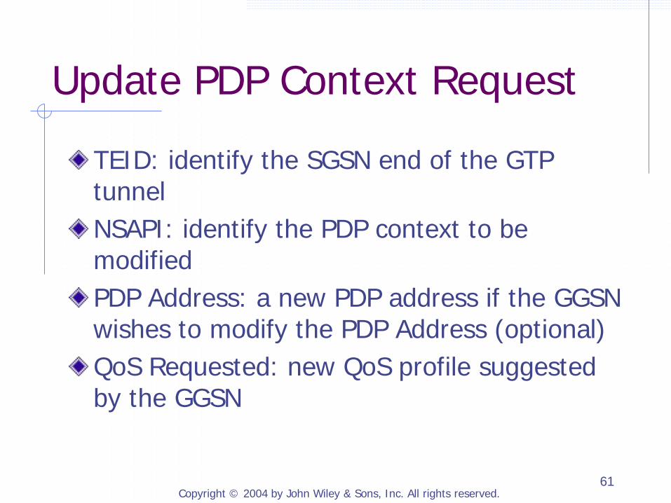
Update PDP Context Request
TEID: identify the SGSN end of the GTP tunnel NSAPI: identify the PDP context to be modified PDP Address: a new PDP address if the GGSN wishes to modify the PDP Address (optional) QoS Requested: new QoS profile suggested by the GGSN
Copyright © 2004 by John Wiley & Sons, Inc. All rights reserved. 62
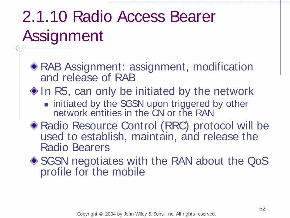
2.1.10 Radio Access Bearer Assignment
RAB Assignment: assignment, modification and release of RAB In R5, can only be initiated by the network initiated by the SGSN upon triggered by other
network entities in the CN or the RAN Radio Resource Control (RRC) protocol will be used to establish, maintain, and release the Radio Bearers SGSN negotiates with the RAN about the QoS profile for the mobile
Copyright © 2004 by John Wiley & Sons, Inc. All rights reserved. 63
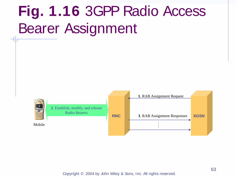
1. RAB Assignment Request
3. RAB Assignment Responses
2. Establish, modify, and release Radio Bearers
RNC SGSN
Mobile
Fig. 1.16 3GPP Radio Access Bearer Assignment
Copyright © 2004 by John Wiley & Sons, Inc. All rights reserved. 64
2.1.11 Packet-Switched Domain Protocol Stacks
2.1.11.1 Gn and Gp interfaces and the GPRS Tunneling Protocol 2.1.11.2 The Iu-PS Interface 2.1.11.3 Gi, Gr, Gc, and Gs Interfaces 2.1.11.4 Mobile-to-GGSN Protocol Stacks

Copyright © 2004 by John Wiley & Sons, Inc. All rights reserved. 65
2.1.11.1 Gn and Gp interfaces and the GPRS Tunneling Protocol
Gn: between SGSN and GGSN as well as SGSNs in the same PLMN Gp: between an SGSN and a GGSN in a different PLMN GPRS Tunneling Protocol (GTP) is used for both user plane and control plane

Copyright © 2004 by John Wiley & Sons, Inc. All rights reserved. 66
Layer 1
Layer 2
IP
UDP
GTP-U
Layer 1
Layer 2
IP
UDP
GTP-U
(a) Gn and Gp Interface User Plane. SGSN GGSN
(b) Gn and Gp Interface Control Plane.
Layer 1
Layer 2
IP
UDP
GTP-C
Layer 1
Layer 2
IP
UDP
GTP-C
SGSN GGSN
Fig. 1.17 3GPP Gn and Gp interface protocol stacks
Copyright © 2004 by John Wiley & Sons, Inc. All rights reserved. 67
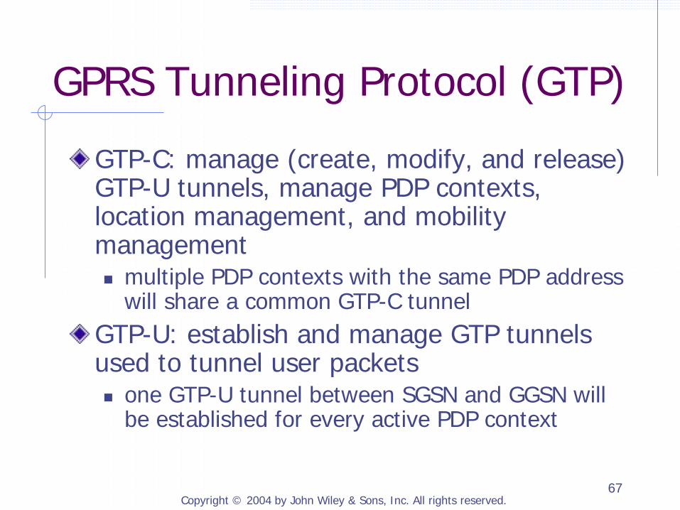
GPRS Tunneling Protocol (GTP)
GTP-C: manage (create, modify, and release) GTP-U tunnels, manage PDP contexts, location management, and mobility management multiple PDP contexts with the same PDP address
will share a common GTP-C tunnel GTP-U: establish and manage GTP tunnels used to tunnel user packets one GTP-U tunnel between SGSN and GGSN will
be established for every active PDP context
Copyright © 2004 by John Wiley & Sons, Inc. All rights reserved. 68
GTP Messages
Tunnel Management: activate, modify and remove PDP Contexts and their associated GTP tunnels Location Management: used by a GGSN to retrieve location information from the HLR Mobility Management: used between SGSNs to transfer mobility related information Path Management: used by a node to determine if a peer node is alive and to inform the peer node of what GTP header extensions it can support
Copyright © 2004 by John Wiley & Sons, Inc. All rights reserved. 69
GTP Header Format Version: 1 for the current version PT (Protocol Type): for 3GPP CN or GPRS/GSM E (Extension header Flag): indicates whether the Next Extension Header is present S (Sequence Number flag): indicates if the Sequence Number field is present PN (N-PDU Number Flag): indicates whether the N-PDU Number field is present Message Type: indicates the type of the GTP message N-PDU Number: used in inter-SGSN Routing Area Update procedure and some inter-system handoff procedures for coordinating data transmission between a mobile terminal and a SGSN

Copyright © 2004 by John Wiley & Sons, Inc. All rights reserved. 70
8 7 6 5 4 3 2 1
PN S E (*) PT Version
Message Type
Length (1st octet)
Length (2nd octet)
Tunnel Endpoint Identifier (1st octet)
Tunnel Endpoint Identifier (2nd octet)
Tunnel Endpoint Identifier (3rdoctet)
Tunnel Endpoint Identifier (4th octet)
Sequence Number (optional) (1st octet)
Sequence Number (optional) (2nd octet)
N-PDU Number (optional)
Next Extension Header Type (optional)
Fig. 2.18 GPRS Tunneling Protocol (GTP) header format
Copyright © 2004 by John Wiley & Sons, Inc. All rights reserved. 71
2.1.11.2 The Iu-PS Interface
Tunnel Management: establishing, maintaining and releasing the GTP tunnels between a RNC and a SGSN Radio Access Bearer Management: establishing, maintaining and releasing Radio Access Bearers (RABs) Radio Resource Management: Radio Resource Admission Control by RNC Mobility Management: handoff between RNC; paging; positioning services

Copyright © 2004 by John Wiley & Sons, Inc. All rights reserved. 72
Layer 1
Layer 2
IP
UDP
GTP-U
Layer 1
Layer 2
IP
UDP
GTP-U
(a) Iu-PS User Plane. RNC SGSN
ATM
AAL 5
Signaling Bearer
SCCP
RANAP
ATM
AAL 5
Signaling Bearer
SCCP
RANAP
(b) Iu-PS Control Plane. RNC SGSN
Fig. 2.19 3GPP Iu-PS interface protocol stacks
RANAP: Radio Access Network Application Part SCCP: Signaling Connection Control Part
Copyright © 2004 by John Wiley & Sons, Inc. All rights reserved. 73
2.1.11.3 Gi, Gr, Gc, and Gs Interfaces
Gi: used by GGSN to connect to any external IP network Gr: between SGSN and HLR Gc: between GGSN and HLR Gs: between SGSN and MSC/VLR

Copyright © 2004 by John Wiley & Sons, Inc. All rights reserved. 74
Layer 1
Layer 2
IP
Layer 1
Layer 2
IP
Gi GGSN External IP Network
Fig. 2.20 3GPP Gi interface protocol stack

Copyright © 2004 by John Wiley & Sons, Inc. All rights reserved. 75
SCCP
Signaling Bearer
Signaling Bearer
SCCP
TCAP
MAP
TCAP
MAP
SGSN or GGSN HLR Gr or Gc
Fig. 2.21 3GPP control-plane protocol stack between SGSN (or GGSN) and HLR
TCAP: Transaction Capabilities Application Part
Copyright © 2004 by John Wiley & Sons, Inc. All rights reserved. 76
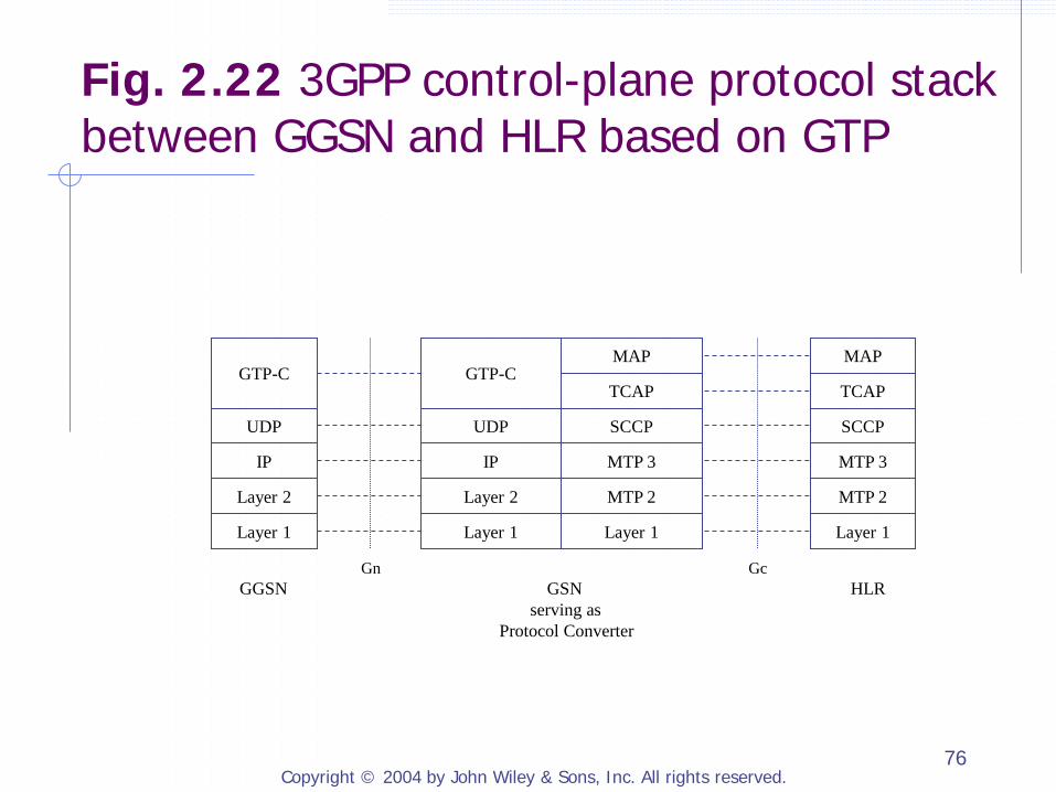
Gn Gc
GGSN GSN HLR serving as Protocol Converter
Layer 1
MTP 2
MTP 3
SCCP
TCAP
MAP
Layer 1
Layer 2
IP
UDP
GTP-C
Layer 1
MTP 2
MTP 3
SCCP
TCAP
MAP
Layer 1
Layer 2
IP
UDP
GTP-C
Fig. 2.22 3GPP control-plane protocol stack between GGSN and HLR based on GTP
Copyright © 2004 by John Wiley & Sons, Inc. All rights reserved. 77
SCCP
Signaling Bearer
Signaling Bearer
SCCP
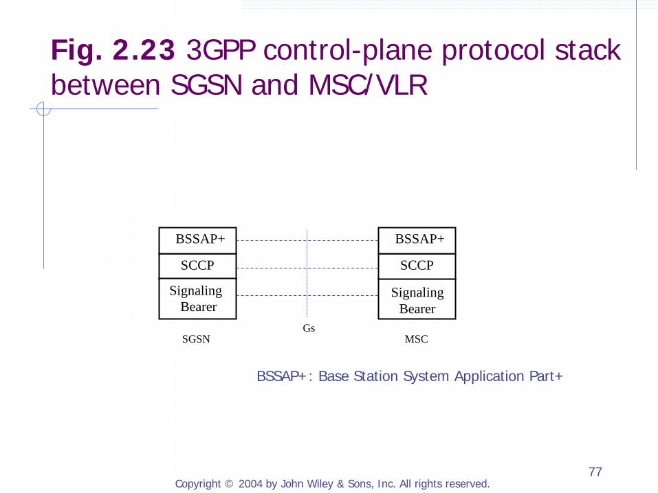
BSSAP+ BSSAP+
SGSN MSC Gs
Fig. 2.23 3GPP control-plane protocol stack between SGSN and MSC/VLR
BSSAP+: Base Station System Application Part+

Copyright © 2004 by John Wiley & Sons, Inc. All rights reserved. 78
2.1.11.4 Mobile-to-GGSN Protocol Stacks
Packet Data Convergence Protocol (PDCP) Header compression for higher-layer data streams
IP Header Compression (IPHC) Robust Header Compression (ROHC)
Mapping higher-layer data into the underlying radio interface protocols
Maintaining data transmission orders for upper layer protocols that have such requirement

Copyright © 2004 by John Wiley & Sons, Inc. All rights reserved. 79
Layer 1
Layer 2
IP
UDP
GTP-U
PDP (e.g., IP, PPP)
Layer 1
Layer 2
IP
UDP
GTP-U
Layer 1
Layer 2
IP
UDP
GTP-U
Layer 1
Layer 2
IP
UDP
GTP-U
Layer 1
MAC
RLC
PDCP
Layer 1
MAC
RLC
PDCP
PDP (e.g., IP, PPP)
MS UTRAN SGSN GGSN Uu Iu-Ps Gn
Applications
Fig. 2.24 3GPP user-plane protocol stack between mobile and GGSN
Copyright © 2004 by John Wiley & Sons, Inc. All rights reserved. 80
Radio Link Control (RLC)
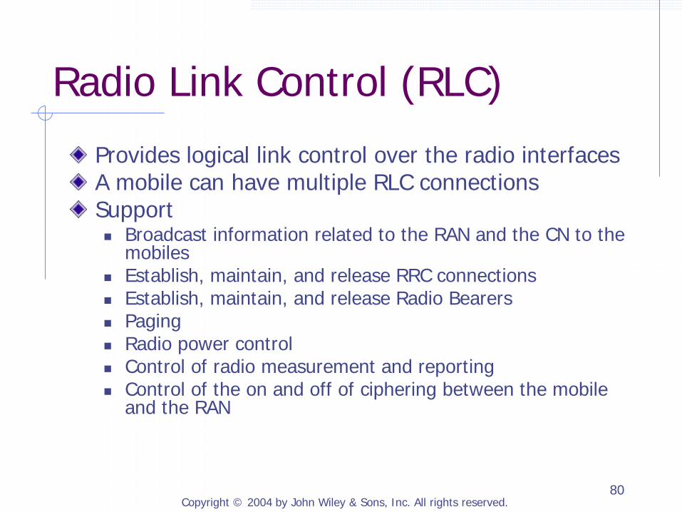
Provides logical link control over the radio interfaces A mobile can have multiple RLC connections Support Broadcast information related to the RAN and the CN to the
mobiles Establish, maintain, and release RRC connections Establish, maintain, and release Radio Bearers Paging Radio power control Control of radio measurement and reporting Control of the on and off of ciphering between the mobile
and the RAN
Copyright © 2004 by John Wiley & Sons, Inc. All rights reserved. 81
ATM
AAL 5
Signaling Bearer
SCCP
RANAP
ATM
AAL 5
Signaling Bearer
SCCP
RANAP
Layer 1
MAC
RLC
RRC
Layer 1
MAC
RLC
RRC
MS RNS SGSN Uu Iu-PS
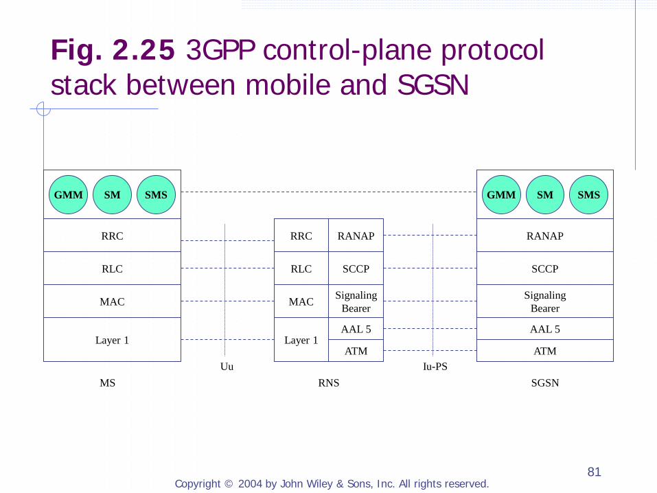
GMM SM SMS GMM SM SMS
Fig. 2.25 3GPP control-plane protocol stack between mobile and SGSN
Copyright © 2004 by John Wiley & Sons, Inc. All rights reserved. 82
GMM, SM, and SMS
GPRS Mobility Management (GMM): support mobility management functions including GPRS Attach and Detach operations, security, and routing area update procedure. Session Management (SM): support PDP context activation, modification, and deactivation SMS (Short Message Service): support short messages

Copyright © 2004 by John Wiley & Sons, Inc. All rights reserved. 83
2.1.12 Accessing IP Networks through PS Domain
User registration (e.g., authentication and authorization) with the external IP network Dynamic assignment of IP addresses to the mobile by the external IP network Encryption of user data transported between the mobile and the external IP network

Copyright © 2004 by John Wiley & Sons, Inc. All rights reserved. 84
External IP Network
3GPP PS Domain
Gi
RAN
Router
User Traffic
SGSN GGSN RNC
Mobile
Fig. 2.26 Access another IP network through 3GPP PS domain
Copyright © 2004 by John Wiley & Sons, Inc. All rights reserved. 85
Transparent Access vs. Non-transparent Access
Transparent Access: The GGSN does not participate in any interaction between the mobile and the external IP network except transporting user packets. Non-transparent Access: The GGSN participates in at least one of the interactions between the mobile and the external IP network described above.
Copyright © 2004 by John Wiley & Sons, Inc. All rights reserved. 86
2.1.12 Accessing IP Networks through PS Domain
2.1.12.1 Transparent Access 2.1.12.2 Non-Transparent Access Using Mobile IP 2.1.12.3 Acquiring IP Address Dynamically Using DHCP from an External Network 2.1.12.4 Dial-up Access Using PPP
Copyright © 2004 by John Wiley & Sons, Inc. All rights reserved. 87
2.1.12.1 Transparent Access
Gain access to a GGSN in the local PS CN Acquire an IP address from the local PS domain to use as its PDP address in local PS CN domain Register with the external IP network

Copyright © 2004 by John Wiley & Sons, Inc. All rights reserved. 88
IP
Layer 2
Layer 1
IP
Layer 2
Layer 1
UDP/TCP
IP
3GPP Packet Domain Bearer
IP
Mobile Terminal GGSN External IP Network
Gi
UDP/TCP
Higher-Layer IP Protocols (e.g., MIP,
IPsec)
Higher-Layer IP Protocols (e.g., MIP,
IPsec)
Fig. 2.27 Protocol stacks for transparent to IP networks through 3GPP PS CN
Copyright © 2004 by John Wiley & Sons, Inc. All rights reserved. 89
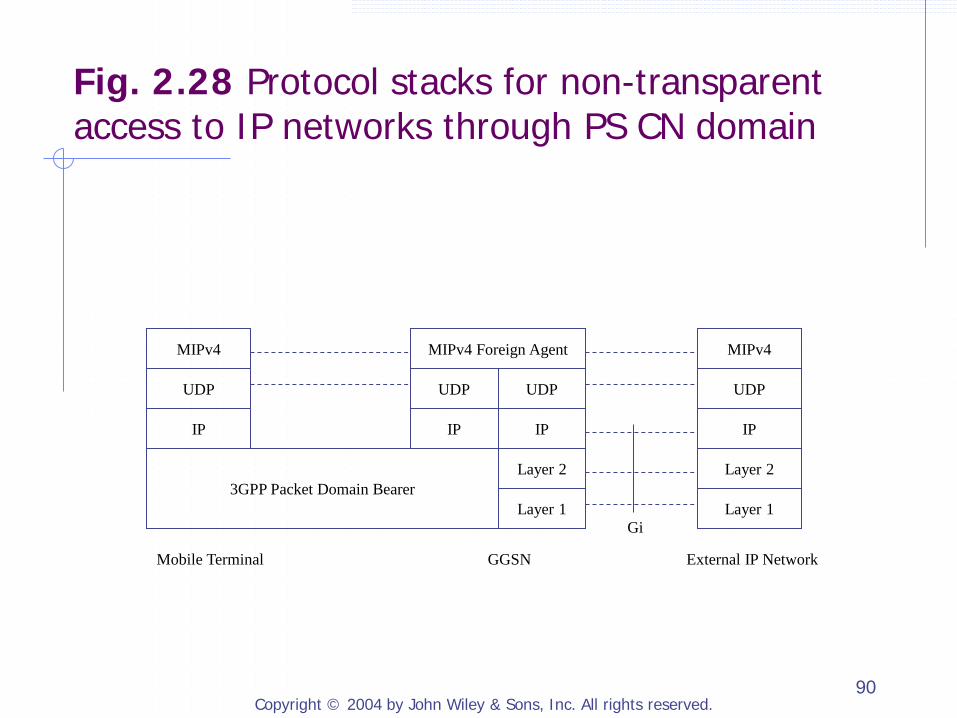
2.1.12.2 Non-Transparent Access Using Mobile IP
GGSN also serves as a MIPv4 FA Mobile uses the IP address of the GGSN as its FA CoA HA may be inside an external IP network
Copyright © 2004 by John Wiley & Sons, Inc. All rights reserved. 90
IP
Layer 2
Layer 1
IP
Layer 2
Layer 1
UDP
IP
3GPP Packet Domain Bearer
IP
Mobile Terminal GGSN External IP Network
Gi
UDP
MIPv4 MIPv4 MIPv4 Foreign Agent
UDP UDP
Fig. 2.28 Protocol stacks for non-transparent access to IP networks through PS CN domain
Copyright © 2004 by John Wiley & Sons, Inc. All rights reserved. 91
Mobile IP HA
GGSN With Mobile IP FA Mobile SGSN
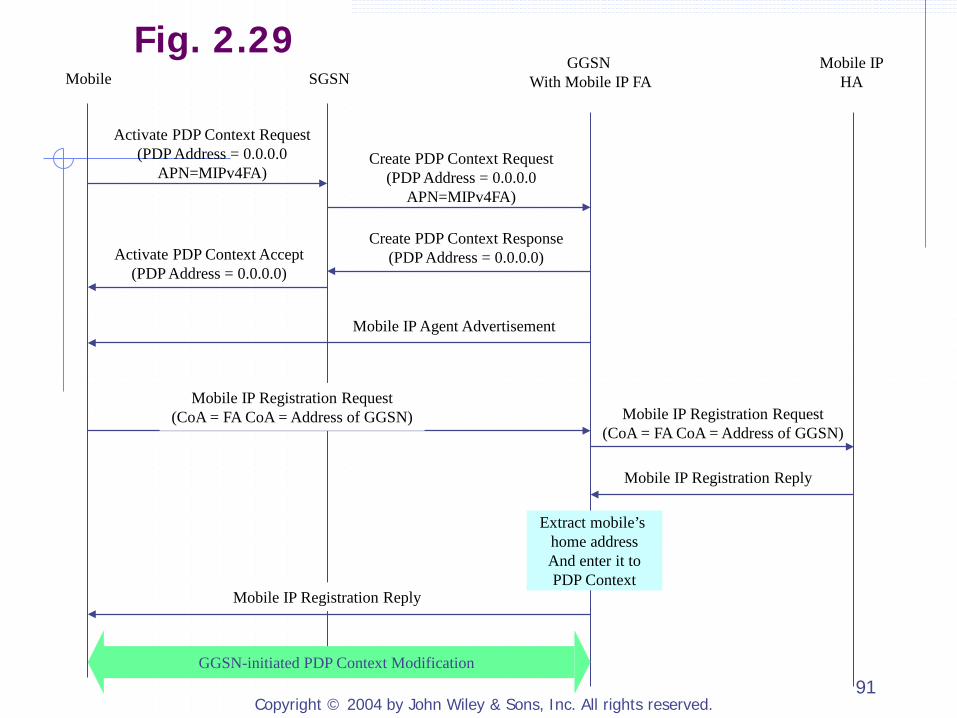
Activate PDP Context Request (PDP Address = 0.0.0.0
APN=MIPv4FA) Create PDP Context Request
(PDP Address = 0.0.0.0 APN=MIPv4FA)
Create PDP Context Response (PDP Address = 0.0.0.0) Activate PDP Context Accept
(PDP Address = 0.0.0.0)
Mobile IP Agent Advertisement
Mobile IP Registration Request (CoA = FA CoA = Address of GGSN) Mobile IP Registration Request
(CoA = FA CoA = Address of GGSN)
Mobile IP Registration Reply
Mobile IP Registration Reply
Extract mobile’s home address And enter it to PDP Context
GGSN-initiated PDP Context Modification
Fig. 2.29

Copyright © 2004 by John Wiley & Sons, Inc. All rights reserved. 92
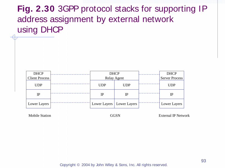
2.1.12.3 Acquiring IP Address Dynamically Using DHCP from an External Network
Before an IP address is assigned to the mobile by the external IP network, the PS CN domain should be able to relay DHCP messages between the mobile and external DHCP server. When an IP address is assigned to the mobile by the external IP network, the mobile’s PDP contexts on the SGSN and the GGSN need to be updated to include the mobile’s IP address.
Copyright © 2004 by John Wiley & Sons, Inc. All rights reserved. 93
Lower Layers
Mobile Station GGSN External IP Network
IP
UDP
DHCP Server Process
Lower Layers
IP
UDP
DHCP Relay Agent
Lower Layers
IP
UDP
Lower Layers
IP
UDP
DHCP Client Process
Fig. 2.30 3GPP protocol stacks for supporting IP address assignment by external network using DHCP

Copyright © 2004 by John Wiley & Sons, Inc. All rights reserved. 94
DHCP Server in External
IP Network
GGSN with
DHCP Relay Agent Mobile SGSN
Activate PDP Context Request (PDP Address = 0.0.0.0) Create PDP Context Request
(PDP Address = 0.0.0.0)
Create PDP Context Response (PDP Address = 0.0.0.0)
Activate PDP Context Accept (PDP Address = 0.0.0.0)
DHCPDISCOVER
DHCPOFFER
DHCPREQUEST
DHCPACK
GGSN-initiated PDP Context Modification
Extract IP Address Assigned to Mobile
DHCPDISCOVER
DHCPOFFER
DHCPREQUEST
DHCPACK
Fig. 2.31
Copyright © 2004 by John Wiley & Sons, Inc. All rights reserved. 95
2.1.12.4 Dial-up Access Using PPP
Dialup refers to the process of establishing a link-layer connection to an IP network PPP connection is a natural choice for implementing the portion of a dialup connection over the PS domain L2TP may be used to extend the PPP connection from GGSN to external IP network
Copyright © 2004 by John Wiley & Sons, Inc. All rights reserved. 96
Lower Layers
IP
UDP
Protocols for tunneling
over IP network (e.g., L2TP)
Lower Layers
IP
UDP
Protocols for tunneling
over IP network (e.g., L2TP)
Mobile GGSN (LAC) LNS in External IP Network
Lower Layers
PPP
Lower Layers
PPP
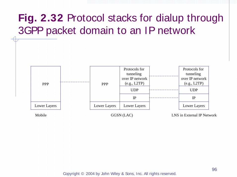
Fig. 2.32 Protocol stacks for dialup through 3GPP packet domain to an IP network
Copyright © 2004 by John Wiley & Sons, Inc. All rights reserved. 97
Mobile
2. Create PDP Context Request (PDD Address = 0.0.0.0)
3. Create PDP Context Response
(PDP Address = 0.0.0.0)
1. Activate PDP Context Request (PDP Address = 0.0.0.0)
4. Activate PDP Context Accept (PDP Address = 0.0.0.0) SGSN GGSN LNS 6. L2TP Negotiation
5. Establish PPP and Configure IP over PPP
Visited Network External IP Network
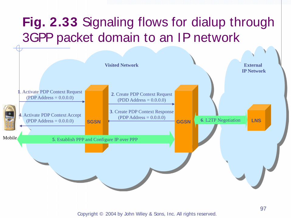
Fig. 2.33 Signaling flows for dialup through 3GPP packet domain to an IP network

Copyright © 2004 by John Wiley & Sons, Inc. All rights reserved. 98
2.2 3GPP2 PACKET DATA NETWORKS
2.2.1 3GPP2 Network Architecture 2.2.2 3GPP2 Packet Data Network Architecture 2.2.3 Protocol Reference Model 2.2.4 Access to 3GPP2 Packet Data Network 2.2.5 User Packet Routing and Transport 2.2.6 Protocol Stacks for Packet Data Services
Copyright © 2004 by John Wiley & Sons, Inc. All rights reserved. 99
2.2.1 3GPP2 Network Architecture
Core network circuit-switched domain packet-switched domain
Radio Networks (RNs): based on circuit-switched technologies and is used for both circuit-switched and packet-switched services
Copyright © 2004 by John Wiley & Sons, Inc. All rights reserved. 100
Radio Networks (RNs)
cdma2000 base station System ID (SID): identify a system Network ID (NID): identify a network pair (SID, NID) (SID, NID): uniquely identify a network within a
system
Base Station (BS) Base Station Controller (BSC) Base Transceiver System (BTS)
Copyright © 2004 by John Wiley & Sons, Inc. All rights reserved. 101
A
Aquater
Aquinter Pi
Pi
Pi
Circuit Switched Core Network
C B
Ai
Radio Network
Packet Switched Core Network
Pi
PDSN PCF
AAA Server HA
MSC
HLR VLR
Servers (e.g., SCP, VMS, MC,
PDE, NPDB, SN)
IP Network
PSTN
BSC BTS
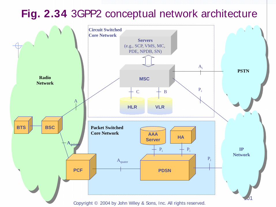
Fig. 2.34 3GPP2 conceptual network architecture
Copyright © 2004 by John Wiley & Sons, Inc. All rights reserved. 102
2.2.1.1 Circuit-Switched Core Network
Switching and call control components Mobile Switching Center (MSC)
Information Servers Home Location Registrar (HLR) Visitor Location Registrar (VLR) Equipment Identity Registrar (EIR)
Service control servers Service Control Point (SCP) Voice Message System (VMS) Message Center (MC) Position Determining Entity (PDE) Number Portability Database (NPDB) Service Node (SN)

Copyright © 2004 by John Wiley & Sons, Inc. All rights reserved. 103
2.2.2 3GPP2 Packet Data Network Architecture
2.2.2.1 Functional Architecture 2.2.2.2 Reference Network Architecture

Copyright © 2004 by John Wiley & Sons, Inc. All rights reserved. 104
2.2.2.1 Functional Architecture
Packet Data Serving Node (PDSN) Packet Control Function (PCF) Radio Resource Control (RRC) Mobile Station (MS) Home Agent (HA) Authentication, Authorization, Accounting (AAA)

Copyright © 2004 by John Wiley & Sons, Inc. All rights reserved. 105
RRC PCF PDSN HA
AAA MS
Fig. 2.35 3GPP2 packet data network functional architecture
Copyright © 2004 by John Wiley & Sons, Inc. All rights reserved. 106
Packet Data Serving Node (PDSN)
Route IP packets between the 3GPP2 network and any external IP networks Route IP packets between mobile terminals inside the same operator’s 3GPP2 network Act as an IP address server to assign IP address to mobiles Act as a PPP server for mobiles (i.e., establish, maintain and terminate PPP session to a mobile terminal) Provide mobility management functions (FA) Communicate with an AAA server to authenticate and/or authorize MS
Copyright © 2004 by John Wiley & Sons, Inc. All rights reserved. 107
Packet Control Function (PCF)
Establish, maintain, and terminate layer-2 connections to the PDSN Maintain reachability information for mobile terminals Relay IP packets between RN and PDSN Tracks status of radio resources Communicate with RRC function on the BSC to manage radio resources
Copyright © 2004 by John Wiley & Sons, Inc. All rights reserved. 108
Radio Resource Control (RRC)
Establish, maintain, and terminate radio connections to mobiles and management radio resources allocated to these connections Broadcast system information to mobiles Maintain status of mobile terminals (e.g., active, dormant)

Copyright © 2004 by John Wiley & Sons, Inc. All rights reserved. 109
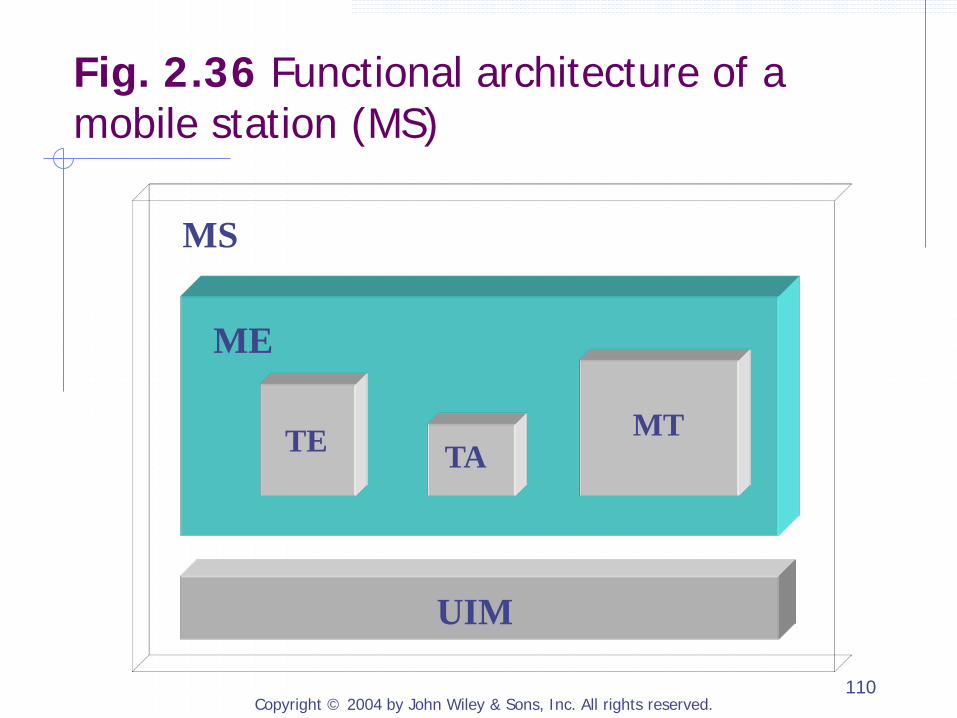
Mobile Station (MS)
User Identity Module (UIM): removable or integrated into ME Mobile Equipment (ME) Terminal Equipment (TE) Mobile Terminal (MT) Terminal Adapter (TA)
Copyright © 2004 by John Wiley & Sons, Inc. All rights reserved. 110
UIM
TE MT TA
ME
MS
Fig. 2.36 Functional architecture of a mobile station (MS)
Copyright © 2004 by John Wiley & Sons, Inc. All rights reserved. 111
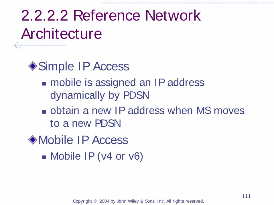
2.2.2.2 Reference Network Architecture
Simple IP Access mobile is assigned an IP address
dynamically by PDSN obtain a new IP address when MS moves
to a new PDSN
Mobile IP Access Mobile IP (v4 or v6)

Copyright © 2004 by John Wiley & Sons, Inc. All rights reserved. 112
Mobile Terminal
SS7 Network
Home Access Provider Network
Home IP Network
Broker AAA Network
Home IP Network, Private Network,
or Home Access
Provider Network
Visited Access Provider Network 1
A10/A11
IP Network
P-P Interface
Visited Access Provider Network 2
PDSN
PDSN
RN
MSC/ VLR
Visited AAA
Home AAA
HLR
AAA
HA
Fig. 2.37 3GPP2 packet data network reference physical architecture
Copyright © 2004 by John Wiley & Sons, Inc. All rights reserved. 113
IPv6
PDSN acts as an IPv6 access router PPP is established between MS and PDSN IPv6 over PPP PDSN sends Router Advertisement MS can use IPv6 stateless autoconfiguration to construct and configure a local IPv6 address
Copyright © 2004 by John Wiley & Sons, Inc. All rights reserved. 114
Relation with CS Network
Many critical capabilities in PS network rely on CS network handoff, paging, connection setup PS network does not directly interface with the CS network CS procedures are initiated by the BSC inside RN upon receiving data or requests from PCF
Copyright © 2004 by John Wiley & Sons, Inc. All rights reserved. 115
2.2.3 Protocol Reference Model
A Reference Point Ater Reference Point Aquinter Reference Point Aquarter Reference Point P-P Interface (optional) PDSN-to-PDSN Interface is used support
fast handoff between PDSNs

Copyright © 2004 by John Wiley & Sons, Inc. All rights reserved. 116
A3 (User Traffic)
A3 (Signaling)
A7 (Signaling)
A1 (Signaling)
A2 (User
Traffic)
A5 (User Traffic)
A Reference Point
A8 (User Traffic)
A9 (Signaling)
A10 (User Traffic)
A11 (Signaling)
Ater Reference Point
Aquinter Reference Point
Aquater Reference Point (R-P interface)
MSC
P-P Interface
Traffic interface Signaling interface
PDSN PCF BSC1 BSC2
PDSN Circuit Switch
Call Control And
Mobility Management
Fig. 2.38 3GPP2 protocol reference model
Copyright © 2004 by John Wiley & Sons, Inc. All rights reserved. 117
A Reference Point
Interface A1: carry signaling traffic between the Call Control and Mobility Management functions of the MSC and the Call Control function of the BSC Interface A2 and A5: carry different types of user traffic between the switch component of MSC and Selection and Distribution Unit (SDU) on BSC

Copyright © 2004 by John Wiley & Sons, Inc. All rights reserved. 118
Ater Reference Point
Interface A3: carry signaling and user traffic between SDU on a source BSC and a target BTS for supporting soft handoff A3 signaling controls the allocation and use of A3
user traffic channels
Interface A7: carry other signaling information not carried by the A3 interface between a source and a target BS
Copyright © 2004 by John Wiley & Sons, Inc. All rights reserved. 119
Aquinter Reference Point
A8 interface: transport user data traffic A9 interface: signaling between a BSC and a PCF The A8 and A9 interfaces are also used to support mobility between BSCs under the same PCF

Copyright © 2004 by John Wiley & Sons, Inc. All rights reserved. 120
Aquarter Reference Point (R-P Interface)
A10 interface: provide a path for user traffic A11 interface: signaling between the PCF and the PDSN The A10 and A11 interfaces are also used to support mobility between PCFs under the same PDSN
Copyright © 2004 by John Wiley & Sons, Inc. All rights reserved. 121
2.2.4 Access to 3GPP2 Packet Data Network
Step 1: Gain access to PDSN Step 1-A: Gain access to the Radio
Network. Step 1-B: Setting up resources between
the BSC and the PDSN. May not need to set up A8 connection
Step 1-C: Establish PPP connection between mobile and PDSN.
Step 2: MIPv4 registration

Copyright © 2004 by John Wiley & Sons, Inc. All rights reserved. 122
Mobile IP Agent Advertisement Mobile IP Registration Request
Authorization Request Authorization
Request Authorization
Response Authorization
Response
Mobile IP Registration Request
Mobile IP Registration Request Reply
Mobile IP Registration Request Reply Accounting Request
Accounting Response
MS PCF PDSN Foreign AAA
Server Home AAA
Server Mobile IP
Home Agent BSC MSC
Origination ACK
CM Service Request
Assignment Request
A9-Setup-A8
Assignment Complete
A9-Connect-A8
Step 1
Step 2
Establish PPP connection
Establish Traffic radio
channel
User packets over PPP
Establish A10
Fig. 2.39 3GPP2 Packet Service Activation (using Mobile IP)
Copyright © 2004 by John Wiley & Sons, Inc. All rights reserved. 123
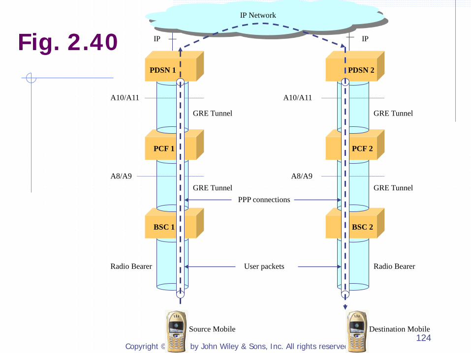
2.2.5 User Packet Routing and Transport
Mobile maintains a PPP connection to its serving PDSN All user packets to and from the mobile will be sent to the serving PDSN first A8 and A10 connections are implemented as IP tunnels using Generic Routing Encapsulation (GRE)
Copyright © 2004 by John Wiley & Sons, Inc. All rights reserved. 124
GRE Tunnel
GRE Tunnel
GRE Tunnel
GRE Tunnel
User packets
IP IP
A10/A11
A8/A9
A10/A11
A8/A9
Radio Bearer Radio Bearer
PDSN 1
PCF 1
BSC 1
PDSN 2
PCF 2
BSC 2
IP Network
PPP connections
Source Mobile Destination Mobile
Fig. 2.40

Copyright © 2004 by John Wiley & Sons, Inc. All rights reserved. 125
2.2.6 Protocol Stacks for Packet Data Services
2.2.6.1 Protocol Stacks over A9 and A11 Interfaces 2.2.6.2 Protocol Stacks over A8 and A10 Interfaces 2.2.6.3 Protocol Stacks over P-P Interface 2.2.6.4 Protocol Stacks Between Mobile and PDSN
Copyright © 2004 by John Wiley & Sons, Inc. All rights reserved. 126
2.2.6.1 Protocol Stacks over A9 and A11 Interfaces
Main messages of A9 A9-Setup-A8 and A9-Connect-A8 A9-Release-A8 and A9-Release-A8 Complete A9-Disconnect-A8 A9-Update-A8 and A9-Update-A8 Ack A9-Air Link (AL) Connected and A9-Air Link (AL)
Connected Ack A9-Air Link (AL) Disconnected and A9-Air Link (AL)
Disconnected Ack
Copyright © 2004 by John Wiley & Sons, Inc. All rights reserved. 127
2.2.6.1 Protocol Stacks over A9 and A11 Interfaces (Cont.)
A11 signaling protocol is modeled after the Mobile IPv4 protocol PDSN acts as if it was a MIPv4 HA PCF acts as if it was a MIPv4 FA
Main messages of A11 A11 Registration Request A11 Registration Reply A11 Registration Update A11 Registration Acknowledge
Soft state: PCF periodically sends A11 Registration Request to refresh A10 connection
Copyright © 2004 by John Wiley & Sons, Inc. All rights reserved. 128
BSC PDSN PCF
Physical Layer Physical Layer
Link Layer Link Layer
IP IP
TCP/UDP UDP
A11 Signaling A9 Signaling
Physical Layer
Link Layer
IP
TCP/UDP
A9 Signaling
Physical Layer
Link Layer
IP
UDP
A11 Signaling
A9 A11
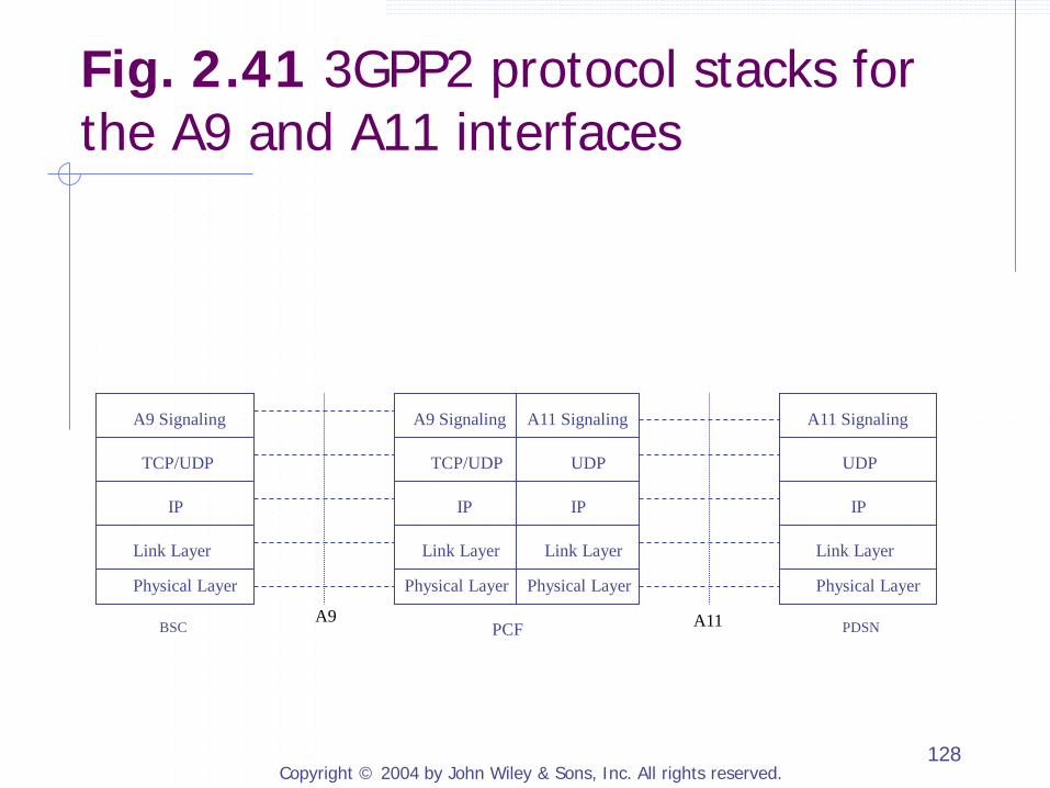
Fig. 2.41 3GPP2 protocol stacks for the A9 and A11 interfaces
Copyright © 2004 by John Wiley & Sons, Inc. All rights reserved. 129
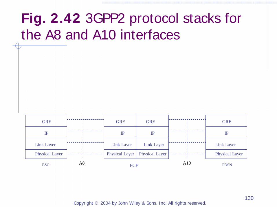
2.2.6.2 Protocol Stacks over A8 and A10 Interfaces
GRE encapsulates a user packet by adding a GRE header to the user packet Sequence Number: ensure packet delivery order Key: identify the IP packets to and from each mobile terminal PCF Session Identifier (PCF SID) PDSN Session Identifier (PDSN SID)
Copyright © 2004 by John Wiley & Sons, Inc. All rights reserved. 130
BSC PDSN PCF
Physical Layer Physical Layer
Link Layer Link Layer
IP IP
Physical Layer
Link Layer
IP
Physical Layer
Link Layer
IP
GRE GRE GRE GRE
A8 A10
Fig. 2.42 3GPP2 protocol stacks for the A8 and A10 interfaces

Copyright © 2004 by John Wiley & Sons, Inc. All rights reserved. 131
C R K S s Recur Flags Ver Protocol Type
Key (optional)
Sequence Number (optional)
Checksum (optional) Offset (optional)
Routing (optional)
0 1 2 3 4 5 6 7 8 9 0 1 2 3 4 5 6 7 8 9 0 1 2 3 4 5 6 7 8 0 1 2
C R K S s Recur Flags Ver Protocol Type
Key
Sequence Number (optional)
0 1 2 3 4 5 6 7 8 9 0 1 2 3 4 5 6 7 8 9 0 1 2 3 4 5 6 7 8 0 1 2
(a) GRE header format.
(b) Format of GRE header used for tunneling between PCF and PDSN or between BSC and PCF.
Fig. 2.43 Generic Routing Encapsulation (GRE) protocol header
Copyright © 2004 by John Wiley & Sons, Inc. All rights reserved. 132
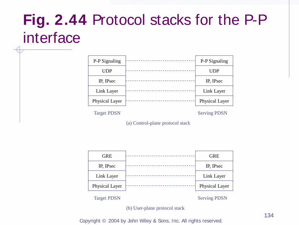
2.2.6.3 Protocol Stacks over P-P Interface
The P-P interface is an optional interface used to support fast inter-PDSN handoff (see 4.4.4) Two individual interfaces P-P Bearer Interface: P-P traffic connection to
tunnel user packets between the PDSNs by GRE tunnel
P-P Signaling Interface: signaling messages and procedures for managing the P-P traffic connections

Copyright © 2004 by John Wiley & Sons, Inc. All rights reserved. 133
P-P Signaling
Modeled after the Mobile IPv4 protocol Serving PDSN acts as if it was a MIPv4 HA Target PDSN acts as if it was a proxy/MIPv4 FA
Main messages of A11 A11 Registration Request A11 Registration Reply A11 Registration Update A11 Registration Acknowledge
Copyright © 2004 by John Wiley & Sons, Inc. All rights reserved. 134
Physical Layer
Link Layer
IP, IPsec
UDP
P-P Signaling
Physical Layer
Link Layer
IP, IPsec
UDP
P-P Signaling
Target PDSN Serving PDSN
(a) Control-plane protocol stack
Physical Layer
Link Layer
IP, IPsec
GRE
Physical Layer
Link Layer
IP, IPsec
GRE
Target PDSN Serving PDSN
(b) User-plane protocol stack
Fig. 2.44 Protocol stacks for the P-P interface
Copyright © 2004 by John Wiley & Sons, Inc. All rights reserved. 135
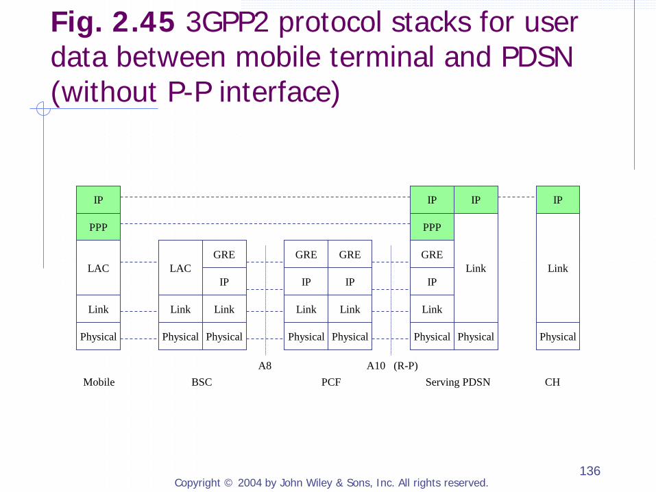
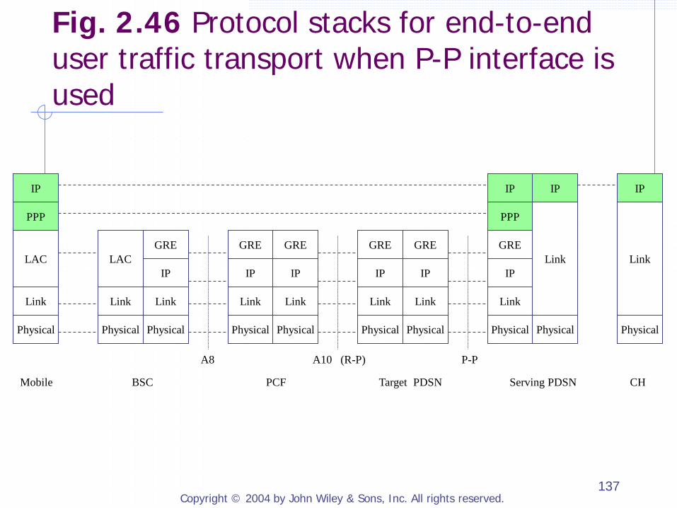
2.2.6.4 Protocol Stacks Between Mobile and PDSN
Mobile is not in the process of fast inter-PDSN handoff (without P-P interface) Link Access Control (LAC): establish, use, modify,
remove of radio links
With P-P interface Signaling between a mobile and its serving PDSN Set up PPP MIPv4 registration
Copyright © 2004 by John Wiley & Sons, Inc. All rights reserved. 136
Mobile BSC PCF Serving PDSN CH A8 A10 (R-P)
Physical
Link
IP
GRE
Physical
Link
IP
GRE
Physical
Link
IP
GRE
Physical
Link
IP
GRE
Physical
Link
LAC
Physical
Link
LAC
PPP
IP
PPP
IP
Physical
IP
Link
Physical
IP
Link
Fig. 2.45 3GPP2 protocol stacks for user data between mobile terminal and PDSN (without P-P interface)
Copyright © 2004 by John Wiley & Sons, Inc. All rights reserved. 137
Mobile BSC PCF Target PDSN Serving PDSN CH
A8 A10 (R-P) P-P
Physical
Link
IP
GRE
Physical
Link
IP
GRE
Physical
Link
IP
GRE
Physical
Link
IP
GRE
Physical
Link
IP
GRE
Physical
Link
IP
GRE
Physical
Link
LAC
Physical
Link
LAC
PPP
IP
PPP
IP
Physical
IP
Link
Physical
IP
Link
Fig. 2.46 Protocol stacks for end-to-end user traffic transport when P-P interface is used
Copyright © 2004 by John Wiley & Sons, Inc. All rights reserved. 138
Physical Physical
Link Link
IP IP
Physical Physical
MAC Link
IP LAC
MAC
LAC GRE GRE GRE
Physical Physical Physical
Link
IP
Link Layer
GRE
A10
Mobile BSC PCF Serving PDSN
A8
MIPv4 Client
MIPv4 Foreign Agent
UDP UDP UDP
IP IP IP
PPP PPP
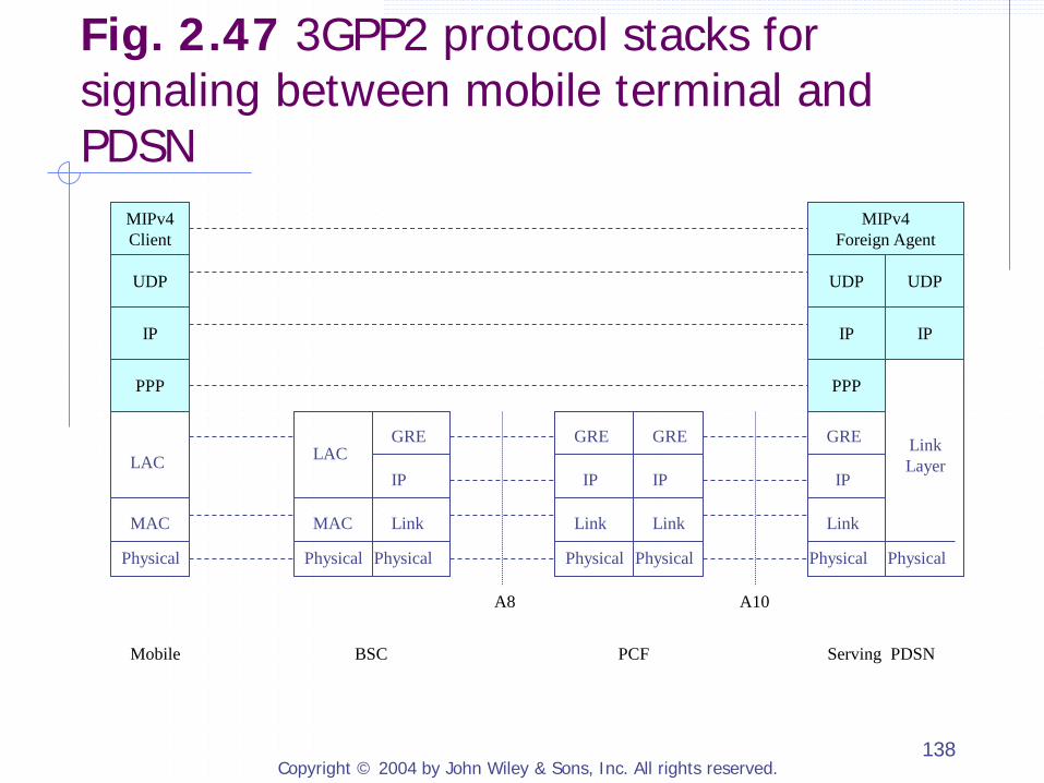
Fig. 2.47 3GPP2 protocol stacks for signaling between mobile terminal and PDSN

Copyright © 2004 by John Wiley & Sons, Inc. All rights reserved. 139
2.3 MWIF ALL-IP MOBILE NETWORKS
MWIF seeks to develop an end-to-end all-IP wireless network that will use IETF protocols to support all networking functions at the network-layer and higher layers, including naming and addressing, signaling, service control, routing, transport, mobility management, quality of service mechanisms, security, accounting, and network management. Unlike the 3GPP and 3GPP2 networks, the MWIF architecture will no longer rely on protocols or network entities in circuit-switched core networks.
Copyright © 2004 by John Wiley & Sons, Inc. All rights reserved. 140
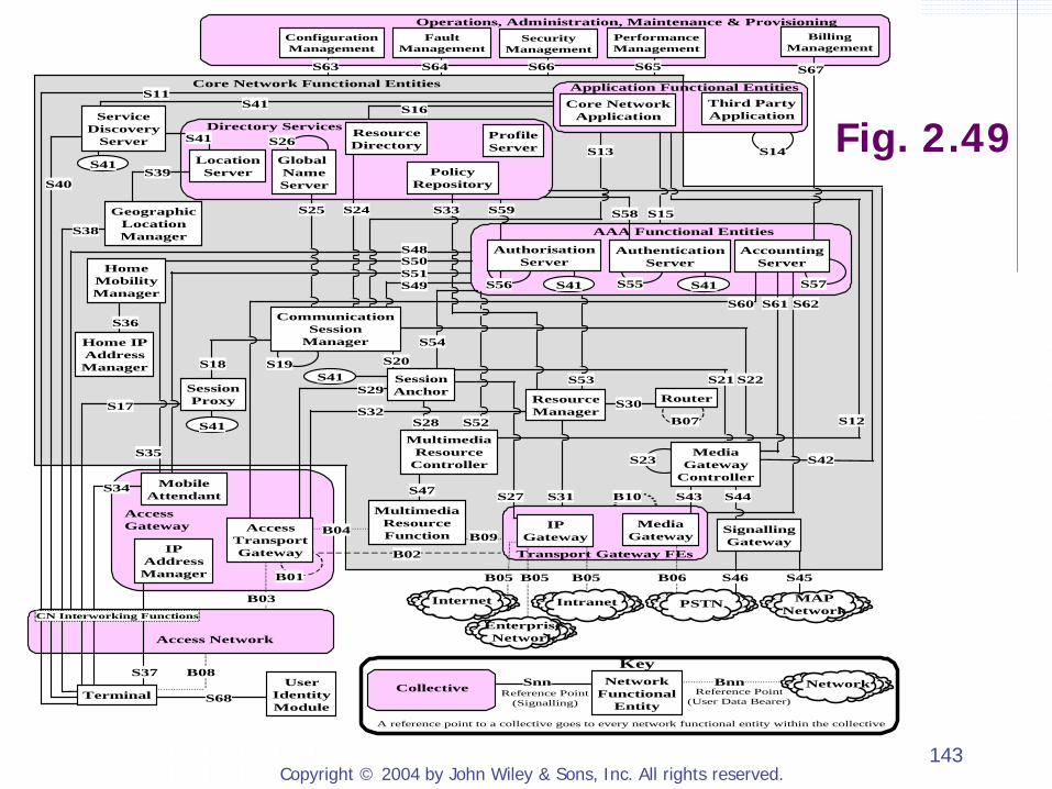
2.3.1 Network Architectures
Core Network All-IP using standard IETF protocols Independent of access-specific
technologies used in different Access Networks
Access Networks

Copyright © 2004 by John Wiley & Sons, Inc. All rights reserved. 141
Layered Functional Architecture
Transport Layer (in both Access Network and Core Network) Control Layer Service Layer Application Layer The security and the OAM&P (Operation, Administration, Maintenance and Provisioning) functions may span across multiple functional layers.
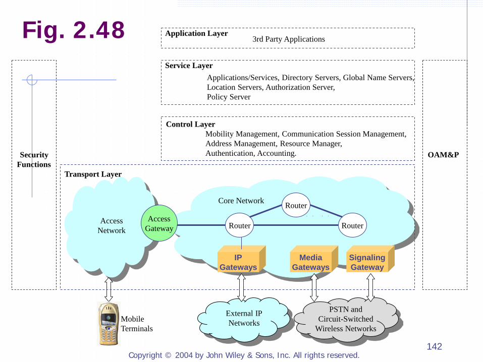
Copyright © 2004 by John Wiley & Sons, Inc. All rights reserved. 142
Security
Functions
OAM&P
Mobile Terminals
Transport Layer
Access Network
Core Network
Router
Router
Router
Mobility Management, Communication Session Management, Address Management, Resource Manager, Authentication, Accounting.
Control Layer
Applications/Services, Directory Servers, Global Name Servers, Location Servers, Authorization Server, Policy Server
Service Layer
Application Layer 3rd Party Applications
Access Gateway
External IP Networks
PSTN and Circuit-Switched
Wireless Networks
IP Gateways
Media Gateways
Signaling Gateway
Fig. 2.48
Copyright © 2004 by John Wiley & Sons, Inc. All rights reserved. 143
S35
S19
S14Global NameServer
Directory ServicesS26
S16
S25
S13
S53
PolicyRepository
S57S55
AAA Functional Entities
S15
S44B10S31 S43
S33
S39
S37
S11
S47
Operations, Administration, Maintenance & Provisioning
S67
BillingManagement
S63 S64 S66 S65
ConfigurationManagement
FaultManagement
PerformanceManagement
SecurityManagement
Access Network
B08User
IdentityModule
S68
Core Network Functional Entities
MAPNetwork
S45S46
SignallingGateway
B06
PSTN
MediaGateway
B05 B05B05
IntranetInternet
EnterpriseNetwork
Collective NetworkFunctional
Entity
Network
KeySnn Bnn
Reference Point(Signalling)
Reference Point(User Data Bearer)
A reference point to a collective goes to every network functional entity within the collective
S30
S41
S41
S41
ServiceDiscovery
Server
LocationServer
S58
B01
ProfileServer
IPAddressManager
S36
GeographicLocationManagerS38
Transport Gateway FEs
S40
S34 MobileAttendant
Home IPAddressManager
Access Gateway
S23
B03
MultimediaResourceFunction
B02
B07
Router
Core NetworkApplication
Application Functional Entities
AuthorisationServer
ResourceDirectory
S24
S12
S42
S52
AccountingServer
S56
AuthenticationServer
Third PartyApplication
AccessTransportGateway
S28
ResourceManager
S21
S27
B09IP
GatewayB04
S59
S41
S41 S41
S41S29
S32
S54
S20
S17
S51HomeMobilityManager
S50
SessionAnchor
S48
S49
SessionProxy
S18
MediaGateway
Controller
MultimediaResource
Controller
CommunicationSession
Manager
S62S61S60
Terminal
CN Interworking Functions
S22
Fig. 2.49
Copyright © 2004 by John Wiley & Sons, Inc. All rights reserved. 144
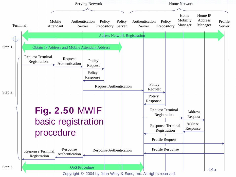
2.3.2 Access to MWIF Networks
Access Network Registration Specific to each access network
Basic Registration for Core Network Enable a mobile to gain access to the core
network and to send and receive IP packets over the core network
SIP Registration Enable a user to use SIP to initiate and receive
multimedia communications An integral part of session and service
management
Copyright © 2004 by John Wiley & Sons, Inc. All rights reserved. 145
Step 2
Step 1
Step 3
Serving Network Home Network
Mobile Attendant
Authentication Server
Policy Repository
Policy Server
Authentication Server
Policy Repository
Home Mobility Manager
Home IP Address Manager
Profile Server Terminal
QoS Procedure
Access Network Registration
Obtain IP Address and Mobile Attendant Address
Request Terminal Registration
Request Authentication
Policy Request
Policy Response
Request Authentication Policy Request
Policy Response
Request Terminal Registration
Address Request
Address Response
Response Terminal Registration
Profile Request
Profile Response Response Authentication Response Authentication
Response Terminal Registration
Fig. 2.50 MWIF basic registration procedure

Copyright © 2004 by John Wiley & Sons, Inc. All rights reserved. 146
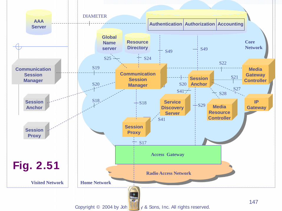
2.3.3 Session Management
2.3.3.1 Functional Entities, Protocol Reference Points and Stacks 2.3.3.2 Mobile-Initiated Call Setup
Copyright © 2004 by John Wiley & Sons, Inc. All rights reserved. 147
Communication Session Manager
Radio Access Network
Core Network
S20
S18
S49
S17
Visited Network
DIAMETER
Home Network
S29
S19
S18
S20 S21
Access Gateway
S22
S27 S28
S41
S41
S49
S24 S25
Communication Session Manager
Session Proxy
Service Discovery
Server
Session Anchor
Media Gateway
Controller
IP Gateway Media
Resource Controller
Session Proxy
Session Anchor
Communication Session Manager
AAA Server Authentication Authorization Accounting
Resource Directory
Global Name server
Fig. 2.51
Copyright © 2004 by John Wiley & Sons, Inc. All rights reserved. 148
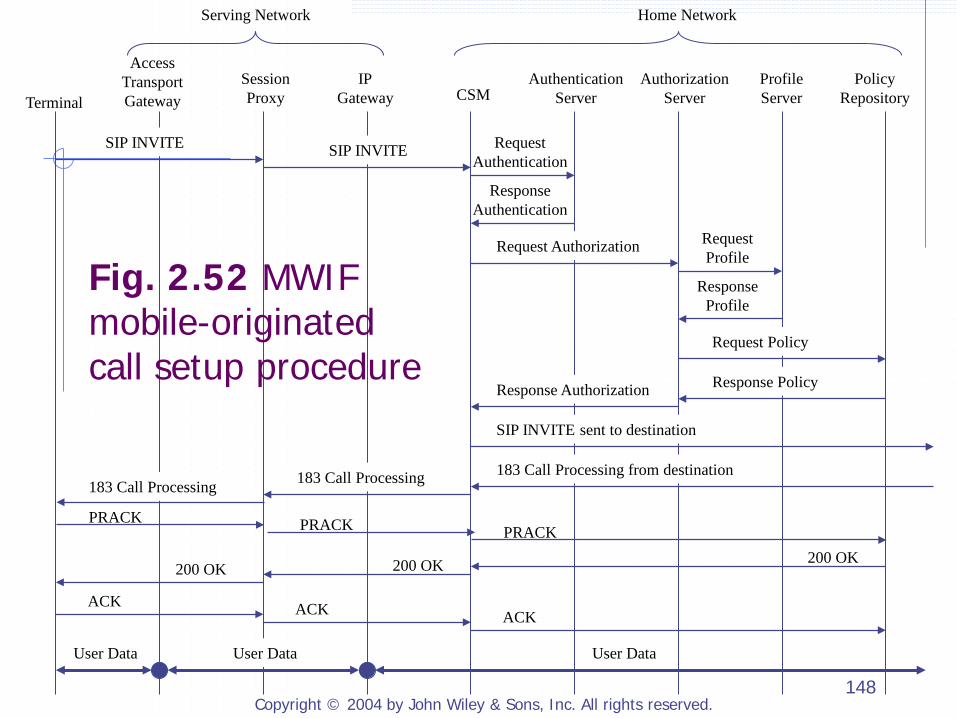
Serving Network Home Network
Access Transport Gateway
Session Proxy CSM
Authentication Server
Authorization Server
Profile Server
Policy Repository Terminal
IP Gateway
SIP INVITE SIP INVITE Request Authentication
Response Authentication
Request Authorization Request Profile
Response Profile
Request Policy
Response Policy Response Authorization
SIP INVITE sent to destination
183 Call Processing from destination 183 Call Processing
PRACK PRACK 200 OK 200 OK 200 OK
ACK ACK ACK
User Data User Data User Data
183 Call Processing
PRACK
Fig. 2.52 MWIF mobile-originated call setup procedure