Embed Size (px)
Citation preview
Chapter 18 REV. 1/09-18-0218-i
Lancair International Inc., Represented by Neico Aviation Inc., Copyright © 2000 , Redmond, OR 97756
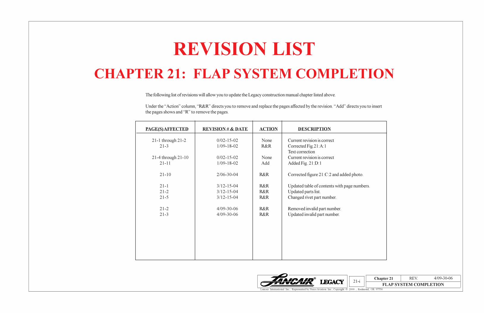
REVISION LIST
CHAPTER 21: FLAP SYSTEM COMPLETION
The following list of revisions will allow you to update the Legacy construction manual chapter listed above.
Under the “Action” column, “R&R” directs you to remove and replace the pages affected by the revision. “Add” directs you to insert
the pages shows and “R” to remove the pages.
PAGE(S) AFFECTED REVISION # & DATE ACTION DESCRIPTION
21-1 through 21-2 0/02-15-02 None Current revision is correct
21-3 1/09-18-02 R&R Corrected Fig.21:A:1
Text correction
21-4 through 21-10 0/02-15-02 None Current revision is correct
21-11 1/09-18-02 Add Added Fig. 21:D:1
21-10 2/06-30-04 R&R Corrected figure 21:C:2 and added photo.
21-1 3/12-15-04 R&R Updated table of contents with page numbers.
21-2 3/12-15-04 R&R Updated parts list.
21-5 3/12-15-04 R&R Changed rivet part number.
21-2 4/09-30-06 R&R Removed invalid part number.
21-3 4/09-30-06 R&R Updated invalid part number.
Chapter 2121-i
FLAP SYSTEM COMPLETION
4/09-30-06

Chapter 21 REV. 0/02-15-02
FLAP SYSTEM COMPLETION21-1
Lancair International Inc., Represented by Neico Aviation Inc., Copyright © 2000 , Redmond, OR 97756
1. INTRODUCTION
The Legacy uses slotted type flaps. That means the flaps pivot about a point below
the wing. As the flaps deploy they follow an arc moving aft and down. The flaps depend
on airflow through the flap slot, hence the reason for the gap opening up as the flaps are
deployed.
The flaps are operated by an electric motor. The electric motor mounts aft of the aft
spar and passes through the aft spar. The travel is set by two limit switches.
2. PARTS LIST
# PART NO. (P/N) QTY DESCRIPTION OPTIONAL ITEM
(not included with kit)
CENTER TORQUE TUBE SUPPORT
1) 4310-01 FB 1 Left Flap
2) 4310-02 FB 1 Right Flap
3) 4551-01 2 Inboard Flap Mount Spacer
4) 4551-02 2 Outboard Flap Mount Spacer
5) 4553 2 Flap Hinge, Inboard, Wing Side
6) 4554 2 Flap Hinge, Outboard, Wing Side
7) 4555 2 Flap Hinge, Inboard, Flap Side
8) 4556 2 Flap Hinge, Outboard, Flap side
9) 4559-01 1 Flap Torque Tube, Left
10) 4559-02 1 Flap Torque Tube, Right
11) 4560 2 Flap Actuator Support Bracket
12) 4562-01 1 Flap Tube Support Bracket, Left
13) 4562-02 1 Flap Tube Support Bracket, Right
14) 4580 1 Flap Activator Arm
15) FL1061-03 2 Flap Torque Tube Bushing
16) FL1A 1 Flap Motor Clevis
17) FL1 1 Flap Motor
18) FL6 1 Flap Motor Bracket
Note:
Optional Parts available through :
(*) Lancair Avionics
(**) Kit Components, Inc.
Chapter 21: Flap System Completion
Contents
1. INTRODUCTION.......................................................................................... 21-1
2. PARTS LIST .................................................................................................. 21-1
3. CONSTRUCTION PROCEDURES ............................................................. 21-3
A. Center Torque Tube Support ..................................................................................... 21-3
B. Flap Installation ......................................................................................................... 21-7
C. Flap Motor Installation ............................................................................................... 21-9
Flap Motor Alignment ..................................................................................................... 21-10
Flap Adjustments ............................................................................................................. 21-10
D. Bonding the Wing Trailing Edge ................................................................................ 21-11
3/12-15-04
Chapter 21 REV. 0/02-15-02
FLAP SYSTEM COMPLETION21-2
Lancair International Inc., Represented by Neico Aviation Inc., Copyright © 2000 , Redmond, OR 97756
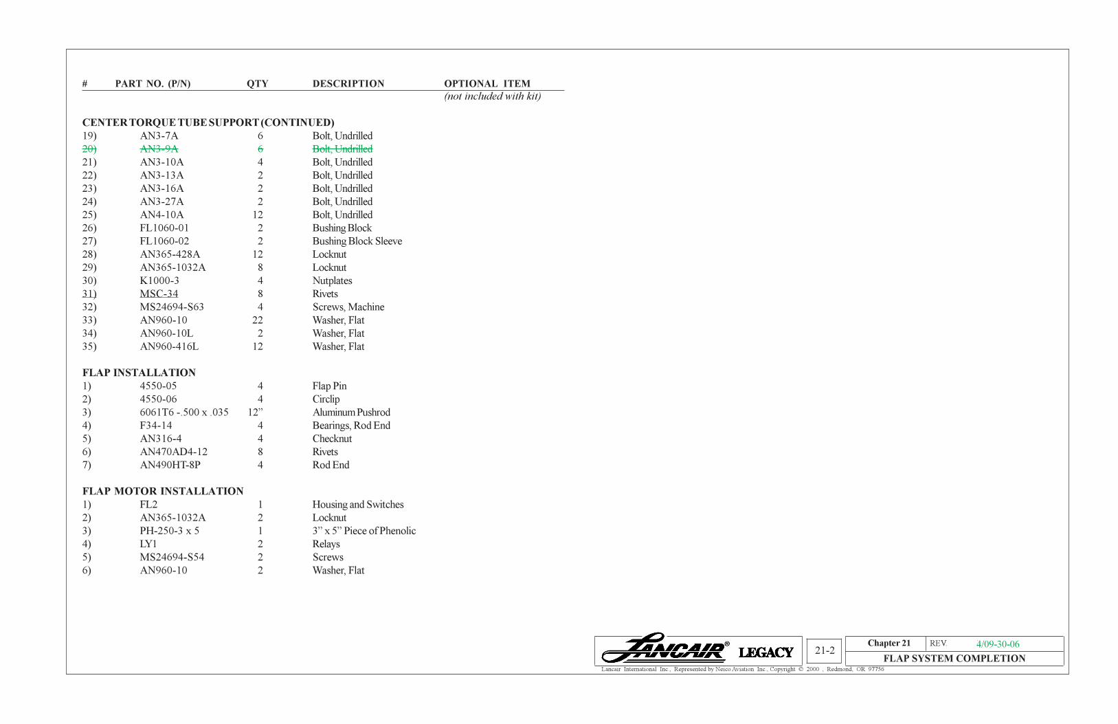
# PART NO. (P/N) QTY DESCRIPTION OPTIONAL ITEM
(not included with kit)
CENTER TORQUE TUBE SUPPORT (CONTINUED)
19) AN3-7A 6 Bolt, Undrilled
20) AN3-9A 6 Bolt, Undrilled
21) AN3-10A 4 Bolt, Undrilled
22) AN3-13A 2 Bolt, Undrilled
23) AN3-16A 2 Bolt, Undrilled
24) AN3-27A 2 Bolt, Undrilled
25) AN4-10A 12 Bolt, Undrilled
26) FL1060-01 2 Bushing Block
27) FL1060-02 2 Bushing Block Sleeve
28) AN365-428A 12 Locknut
29) AN365-1032A 8 Locknut
30) K1000-3 4 Nutplates
31) MSC-34 8 Rivets
32) MS24694-S63 4 Screws, Machine
33) AN960-10 22 Washer, Flat
34) AN960-10L 2 Washer, Flat
35) AN960-416L 12 Washer, Flat
FLAP INSTALLATION
1) 4550-05 4 Flap Pin
2) 4550-06 4 Circlip
3) 6061T6 -.500 x .035 12” Aluminum Pushrod
4) F34-14 4 Bearings, Rod End
5) AN316-4 4 Checknut
6) AN470AD4-12 8 Rivets
7) AN490HT-8P 4 Rod End
FLAP MOTOR INSTALLATION
1) FL2 1 Housing and Switches
2) AN365-1032A 2 Locknut
3) PH-250-3 x 5 1 3” x 5” Piece of Phenolic
4) LY1 2 Relays
5) MS24694-S54 2 Screws
6) AN960-10 2 Washer, Flat
3/12-15-043/12-15-044/09-30-06

Chapter 21 REV. 0/02-15-02
FLAP SYSTEM COMPLETION21-3
Lancair International Inc., Represented by Neico Aviation Inc., Copyright © 2000 , Redmond, OR 97756
3. CONSTRUCTION PROCEDURES
A. Center Torque Tube Support
Step 1 - We’ll break this up into 3 easy
steps:
1. Mount the torque tube.
2. Install the flap motor.
3. Set the limit switches.
Flap Tube Support Bracket, Left
4562-01 (1 pc.)
Inboard Flap Attach Bracket,
4557-01 (ref.)
Outboard Flap Attach Bracket, 4558 (ref.)
Outboard Flap Hinge, Flap Side, 4556 (2 pc.)
Flap Access Panels
4552 (ref.)
Left Flap,
4310-01 FB
Flap Actuator Support Bracket,
4560 (2 pcs.)
Inboard Flap Mount Spacer,
4551-01 (2 pcs.)
Bearing Block Assembly
See Fig. 21:A:3
Flap Actuator
Pushrod
See Fig. 21:B:2
Flap Torque Tube Bushing,
FL1061-03 (2 pcs.) Flap Tube Support Bracket, Right, 4562-02 (1 pc.)
Inboard Flap Attach Bracket, 4557-02 (ref.)
Flap Hinge, Inboard, Wing Side,
4553 (2 pcs.) Right Flap,
4310-02 FB
Inboard Flap Hinge, Flap Side, 4555 (2 pcs,)
Inboard Flap Mount Spacer
4551-01 (2 pcs.)
Flap Actuator Support Bracket, 4560 (2 pcs.)
Flap Motor Clevis, FL1A (1 pc.)
Flap Motor, FL1 (limit switches not shown)
Flap Motor Bracket, P/N FL6 mounts to the
floor in the baggage compartment.
Flap Torque Tube, Right
4559-02 (1 pc.)
Flap Actuator Arm,
4580 (1 pc.)
Flap Torque Tube, Left
4559-01 (1 pc.)
Flap pin and circlips (included
with flap motor)
Outboard Flap Attach Bracket, 4558 (ref.)
Outboard Flap Hinge, Wing Side, 4554 (2 pcs.)
Outboard Flap Hinge, Flap Side, 4556 (2 pc.)
Outboard Flap Hinge, Wing Side, 4554 (2 pcs.)
Bolts, AN3-7A (6 pcs.)
or AN3-10A, depending
on material thickness.
Bolt, AN4-10A (12 pcs.)
Washer, AN 960-416L (12 pcs.)
Nut, AN365-428A (12 pcs.)
Flap Hinge, Inboard, Wing Side, 4553 (2 pc.)
Bolt, AN3-7A (4 pcs.)
Inboard Flap Nutplate Mount,
4551-02 (2 pcs. not shown)
Inboard Flap Hinge, Flap Side, 4555 (2 pcs.)
Bolt, AN3-7A (2 pcs.)
Washer, AN960-10L (2 pcs.)
Locknut, AN365-1032A(2 pcs.)
Locknut, AN365-1032A (4 pcs.)
Washer, AN960-10 (4 pcs.) Machine Screw, MS24694-S63 (4 pcs.)
Washer, AN960-10 (4 pcs.)
Bolt, AN3-13A (2 pcs.)
Washer, AN960-10 (8 pcs.)Bolt, AN3-16A (2 pcs.)
Inboard Flap Mount Spacer,
4551-02 (2 pcs. not shown)
Outboard Flap Rib, 4316-01 (ref.)
Outboard Flap Rib, 4316-02 (ref.)
WARNING: Bolt lengths and screw lengths may vary. ALWAYS
check for sufficient number of threads through the fastener.
1/09-18-02
Flap Assembly Exploded View
Fig. 21:A:1
4/09-30-06

Chapter 21 REV. 0/02-15-02
FLAP SYSTEM COMPLETION21-4
Lancair International Inc., Represented by Neico Aviation Inc., Copyright © 2000 , Redmond, OR 97756
Locating Torque Tube Center
Fig. 21:A:2
String
Center Con-
sole
Right Side, 1 3/8” dia.
hole
Aft Seat
Typical oblongated hole to find the center.
Keep grinding away until the string is clear.
Left Side 1 1/8” hole
Wood Dowel
Left Torque Tube Support
Torque Tube
Passage Hole
Inboard Rib
Step 1. Temporarily mount the flap torque tube supports using
the existing hardware. The screws provided should
be long enough to accomodate the supports.
Step 2. Install a 1 3/8” dia. wood dowel or equivalent with a center hole into
the flap attach bracket.
Step 3. As close as possible, estimate the center of the hole in the center con-
sole. Start by drilling a small hole in the center console and open up as
required to get an accurate reference for the center hole.
Left Side: Centered on the string produce a 1/8” diameter hole.
Right Side: Centered on the string produce a 1 3/8” diameter hole.
PULL THE STRING TIGHT!
This hole is not used
In order to mount the torque tube we must first
establish the center line of the torque tube in the center
console.

Chapter 21 REV. 0/02-15-02
FLAP SYSTEM COMPLETION21-5
Lancair International Inc., Represented by Neico Aviation Inc., Copyright © 2000 , Redmond, OR 97756
Mounting Center Bearing Block
Fig. 21:A:3
Secure K1000-3 nutplates with MSC-34 rivets.
Slot for the flap torque tube.
Seat Support Flange
Locknut,
AN365-1032A (2 pcs.)
Washer,
AN960-10 (2 pcs.)
Flap Bushing Block Sleeve,
FL1060-02 (2 pcs.)
Bushing Block,
FL1060-01 (2 pcs.)
Washer,
AN960-10 (4 pcs.)
Bolt,
AN3-10A (4 pcs.)
Bolt
AN3-27A (2 pcs.)
Center Console Flange
Yes sir, it is a tight installation!
If you need to, it is acceptable to
remove material off the center console
flange and/or material off the lower aft edge
of the bearing block.
Once you have drilled the 1 1/8” diameter hole, position the bearing block on the center console. The bearing block
(including the hardware) must clear the floor and be below the seat support flange. Angle the bearing block to accomplish this.
Once aligned, drill the four 3/16” diameter mounting holes. Next produce a slot large enough to accommodate the flap torque
tube.
3/12-15-04

Chapter 21 REV. 0/02-15-02
FLAP SYSTEM COMPLETION21-6
Lancair International Inc., Represented by Neico Aviation Inc., Copyright © 2000 , Redmond, OR 97756
Flap Torque Tube Support Installation
Fig. 21:A:4
Notice the clocking of the flap
torque tube to the actuator arm. When
assembling verify proper clocking.Flap Actuator Pushrod
Flap Hinge, 4554
Wing Side
Flap Hinge, Flap Side,
4556
TOP VIEW SHOWN IN
“UP” POSITION
Center
ConsoleInboard Rib
Right Flap Torque Tube, 4559-02
Aircraft
Centerline
Left Flap Torque Tube, 4559-01
Flap Torque Tube Support
Bracket
The bushing should be up
against the torque tube arms.
Torque Tube Arm,
Flap Tube Support Bracket
4562-01/02
Flap Torque Tube Bushing
FL1061-03 (2 pcs.)
Flap Attach Bracket
4557-01/02 (Ref.)
FLAP
CL
Flap Actuator Arm,
4580
Set the flap torque tube support such that the
torque tube is centered on the aircraft centerline.
SIDE VIEW LOOKING INBOARD
SHOWN IN “UP” POSITION
Inboard Rib

Chapter 21 REV. 0/02-15-02
FLAP SYSTEM COMPLETION21-7
Lancair International Inc., Represented by Neico Aviation Inc., Copyright © 2000 , Redmond, OR 97756
Flaps Installation
Fig. 21:B:1
WARNING: Once the flaps are installed, protect them from
slamming down. This may damage the flap hinges.
Slot as necessary for ad-
equate actator arm and pushrod
clearance.
Circlip
4550-06
Inboard Flap Hinge (Flap Side)
4555 (Ref,)
Inboard Flap Hinge (Wing Side)
4554 (ref.)
Flap Pin
4550-05
Wing Fillet
Up
Outbd.
Fwd
IMPORTANT: You must properly Install the circlip and
safety wire.
Hole for .032” safety wire
B. Flap Installation
Chapter 21 REV. 0/02-15-02
FLAP SYSTEM COMPLETION21-8
Lancair International Inc., Represented by Neico Aviation Inc., Copyright © 2000 , Redmond, OR 97756
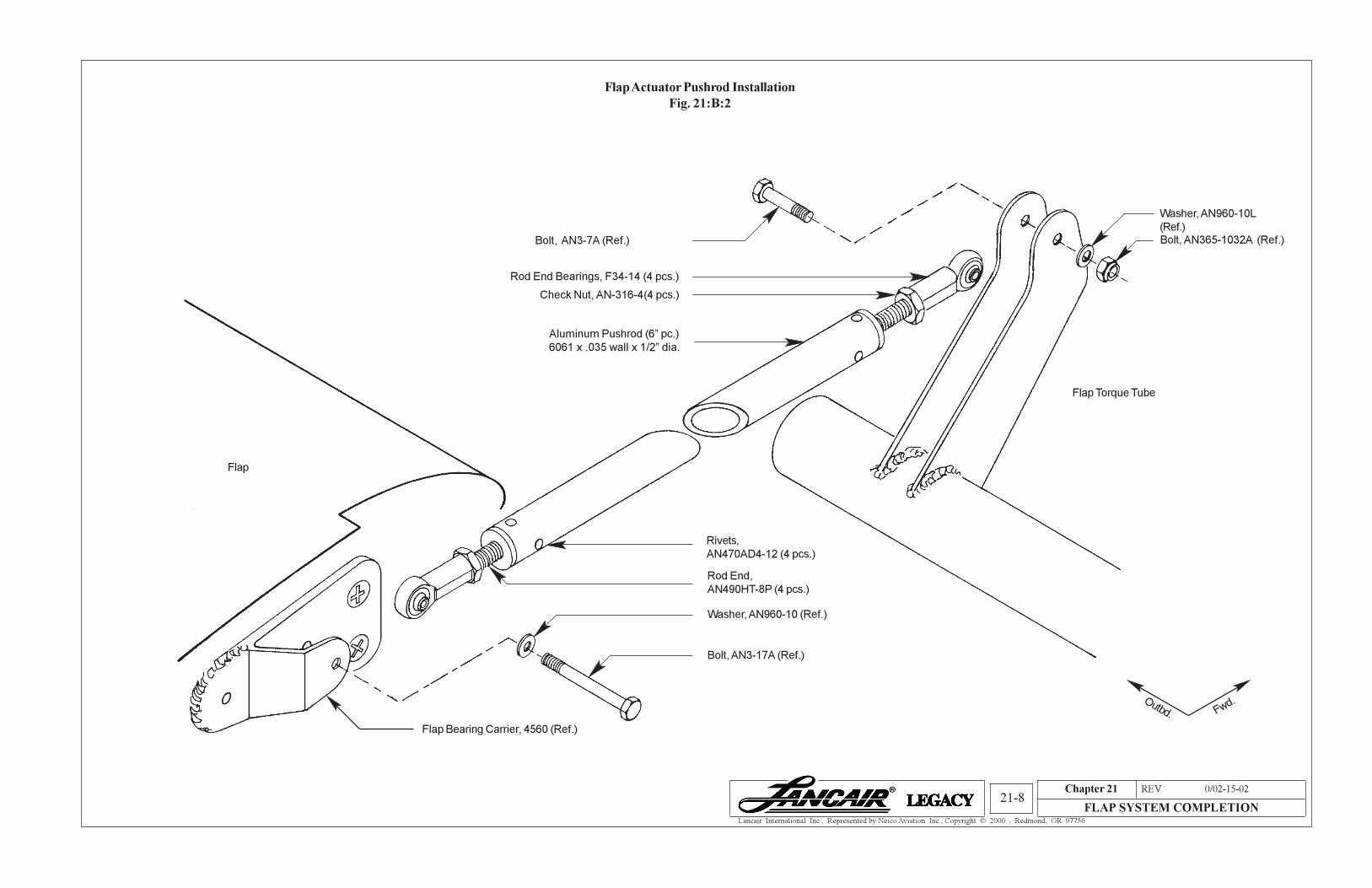
Flap Actuator Pushrod Installation
Fig. 21:B:2
Rod End Bearings, F34-14 (4 pcs.)
Check Nut, AN-316-4(4 pcs.)
Flap Torque Tube
Aluminum Pushrod (6” pc.)
6061 x .035 wall x 1/2” dia.
Rod End,
AN490HT-8P (4 pcs.)
Flap Bearing Carrier, 4560 (Ref.)
Flap
Fwd.Outbd.
Bolt, AN3-17A (Ref.)
Washer, AN960-10 (Ref.)
Bolt, AN3-7A (Ref.)
Washer, AN960-10L
(Ref.)
Bolt, AN365-1032A (Ref.)
Rivets,
AN470AD4-12 (4 pcs.)

Chapter 21 REV. 0/02-15-02
FLAP SYSTEM COMPLETION21-9
Lancair International Inc., Represented by Neico Aviation Inc., Copyright © 2000 , Redmond, OR 97756
Flaps Actuator Mechanism Exploded View
Fig. 21:C:1
Flap Actuator Arm,
4580 (Ref.)
Flap Motor Attach Plate
Flap Motor Clevis,
FL1A (Ref.)
Check Nut, (included with
clevis)Flap Torque Tube
(Ref.)
Flap Motor, FL1
(Ref.)
Flap Motor Clevis Pin and
Circlips (included with motor)
Flap Motor Bracket,
FL-6 (Ref.)
3” x 5” Piece of Phenolic,
PH-250-3 x 5
Screws,
MS24694-S54 (2 pcs.)
Bevel
Edges
1. Center the flap motor bracket on the piece of
phenolic.
2. Countersink the holes.
3. Grind the heads of screws as shown.
4. Sand bottom.
5. Pot in place with epoxy/flox.
Grind the sides of the heads
flat.
The electric flap motor mounts aft of the aft
spar. It mounts to a phenolic attach plate which is
bonded to the fuselage floor.
Nut, AN365-1032A (2 pcs.)
Washer, AN960-10 (2 pcs.)
C. Flap Motor Installation

Chapter 21 REV. 0/02-15-02
FLAP SYSTEM COMPLETION21-10
Lancair International Inc., Represented by Neico Aviation Inc., Copyright © 2000 , Redmond, OR 97756
Flap Motor Location
Fig. 21:C:2
Flap Motor Alignment
1. The flap installs on the aircraft center line
2. The aft edge of the flap bracket is 17 1/2” aft of the aft spar.
Flap Adjustments
The flaps can be adjusted at each of the rod ends as well as adjusting the flap motor.
1. The flaps should be adjusted to be symmetrical. Use the short push rods to adjust as
necessary. Be sure to tighten the check nuts when completed. Also check the tag
wire holes of the rod end bearings to ensure you have enough thread.
2. Set the micro switches so the control horn stops approximately 1/4” (4mm) short of
the aft shear panel. See Chapter 27.
3. Set the micro switches so the maximum flap deflection is 40°. Perhaps the easiest
method of accomplishing this is to use a SMART level or inclinometer.
Aft Spar
Flap
Actuator
Arm
We suggest using a punch to
create a hole for the studs.
Extend the 6 BID 1” past the
phenolic in all directions.
Flap Motor
Bracket
6 BID
Bond the phenolc in place using approved bonding procedures.
Phenolic
1”
1”
17.5”
2/06-30-04
Note that the
sensor cants
slightly clockwise.
Carefully check the clearance
through the aft spar.
Edge of
bracket

Chapter 21 REV. 0/02-15-02
FLAP SYSTEM COMPLETION21-11
Lancair International Inc., Represented by Neico Aviation Inc., Copyright © 2000 , Redmond, OR 97756
Bonding Wing Trailing Edge
Fig. 21:D:1
Rigid Trailing Edge
A/C UP
FORWARD
D. Bonding the Wing Trailing Edge
In Chapter 10 you closed out the inboard wing section. We suggested you hold off on closing out the
trailing edge in the flap cove area. The reason for holding off on this is to check for adequate flap/trailing edge
clearances. We recommend reading this entire section before getting started.
1. Use a rigid straight edge such as a “U” channel to hold the trailing edge straight. We
suggest using bondo to secure the straight edge.
2. Install the flap. Move to the full up position. One method for determining the “full
up” position is to install the aileron. The aileron should align to the wing tip, and flap
to the aileron. Note that the flap may actually be moved past the “full up” position.
With the flap in place, visually inspect the trailing edge gap. You should have
approximately 1/8 " gap. Most likely, you will need to trim some off the trailing
edge to get the gap you need. Once you have sufficient gaps, you are ready to
bond the trailing edge.
3 Using approved bonding procedures, bond the trailing edge.
TYPICAL FLAP CROSS SECTION
1/8"
Clearance
A/C UP
FORWARD
1/09-18-02