Embed Size (px)
Citation preview
Topic #625-000-007 January 1, 2006 Plans Preparation Manual, Volume I - English
Design Exceptions and Design Variations 23-i
Chapter 23
Design Exceptions and Design Variations
23.1 General .....................................................................................23-1
23.2 Design Exceptions ....................................................................23-2 23.2.1 Coordination and Conceptual Concurrence..............23-2 23.2.2 Justification and Documentation ...............................23-3 23.2.3 Approval and Concurrence .......................................23-6 23.2.4 Sealing ......................................................................23-6 23.2.5 Concurrence Review.................................................23-6 23.2.6 Copies and Distribution.............................................23-7
23.3 Design Variations ......................................................................23-8
23.4 AASHTO Criteria for Critical Design Elements..........................23-9
Tables Criteria Tables Cross Reference.............................................................23-9
Exhibits Exhibit 23-A Sample Request Letter for Design Exception .........23-19
Exhibit 23-B Sample Request Letter for Design Variation...........23-20
Exhibit 23-C Design Exceptions Variations and Utility Exceptions Process ...................................................................23-21

Topic #625-000-007 January 1, 2006 Plans Preparation Manual, Volume I - English
Design Exceptions and Design Variations 23-ii
THIS PAGE LEFT BLANK INTENTIONALLY

Topic #625-000-007 January 1, 2006 Plans Preparation Manual, Volume I - English
Design Exceptions and Design Variations 23-1
Chapter 23
Design Exceptions and Design Variations
23.1 General
The Department's roadway design criteria and standards are contained in this volume and are usually within the desirable ranges established by AASHTO. The values given in this volume have been accepted by FHWA and govern the design process. When it becomes necessary to deviate from the Department’s criteria, early documentation and approval are required. There are two documentation and approval processes, Design Exceptions and Design Variations. When the Department’s criteria are met, no Design Exception nor any Design Variation is required. However, when the Department’s criteria are not met, a Design Exception or Design Variation is required. This requirement applies to all entities affecting planning, design, construction, maintenance and utility placement.
To expedite the approval and/or final concurrence of these deviations, it is important that the correct processes be followed. This chapter includes specific coordination, approval, concurrence and documentation requirements for both Design Exceptions and Design Variations. In both cases, the project file should clearly document the action taken and approval given. To aid in the identification and processing of Design Exceptions and Design Variations a process flowchart, Exhibit 23-C, has been provided.
When design criteria are not met for utilities, the process in the current Utility Accommodation Manual (Topic No. 710-020-001) is to be used.
Safety improvement projects are generally developed to address specific safety problems. Only items identified under the scope of work for the safety improvement project must meet design criteria and are subject to the design exception or design variation process. Existing features within the limits of the safety improvement project that do not meet design criteria and are not being addressed as part of the project do not require a design exception or design variation.
When the Department enters into an agreement with a Utility for joint use of a utility pole, and the Department requires the location of the pole to not be in compliance with the applicable horizontal clearance requirements, the Department or Consultant Design Engineer is responsible for the design variation or exception.

Topic #625-000-007 January 1, 2006 Plans Preparation Manual, Volume I - English
Design Exceptions and Design Variations 23-2
23.2 Design Exceptions
Design Exceptions are required when neither the Department’s criteria nor AASHTO’s criteria can be met for any one of the following 13 Critical Design Elements, which are typically safety related issues:
1. Design Speed 6. Vertical Clearance 10. Horizontal Alignment 2. Lane Widths 7. Grades 11. Vertical Alignment 3. Shoulder Widths 8. Cross Slope 12. Stopping Sight Distance 4. Bridge Widths 9. Superelevation 13. Horizontal Clearance 5. Structural Capacity
23.2.1 Coordination and Conceptual Concurrence
In order to allow time to research alternatives and begin the analysis and documentation activities, it is critical that Design Exceptions be identified as early in the process as possible. This is preferably done during the PD&E process for major projects and the scope development process for minor projects. It is required that approval be obtained no later than the initial engineering phase.
When the need for a Design Exception has been determined, the District Design Engineer must coordinate with the State Roadway Design Engineer’s Office. The appropriate Area Design Engineer will assist in obtaining conceptual concurrence and in identifying the necessary level of effort for justification and documentation.
For Design Exceptions requiring FHWA approval, the State Roadway Design Engineer’s Office will coordinate with FHWA to obtain conceptual concurrence and any required documentation requested by FHWA.
Design Exceptions impacting a structure require concurrence of both the State Roadway Design Engineer and the State Structures Design Engineer. Conceptual concurrence should first be obtained from the appropriate Area Engineer in the State Structures Design Office, and decisions or special conditions documented for Design Exception support.
This coordination effort will expedite the approval and concurrence process.

Topic #625-000-007 January 1, 2006 Plans Preparation Manual, Volume I - English
Design Exceptions and Design Variations 23-3
23.2.2 Justification and Documentation
Once conceptual concurrence of the Design Exception has been coordinated and completed, the justification must be documented. The objective of the justification of Design Exceptions is to demonstrate that the impacts on the operation and safety of the facility are acceptable, compared to the impacts and added benefits of meeting the criteria.
All Design Exceptions shall include documentation sufficient to justify the request and independently evaluate the operational and safety impacts. Design Exceptions must address the following issues unless otherwise agreed upon during conceptual concurrence: 1. Description
a. Project description (general project information, typical section, begin/end milepost, county section number, etc.).
b. Description of the Design Exception (specific project conditions related to Design Exception, Critical Design Element, acceptable AASHTO and Department value and proposed value for project).
c. The compatibility of the design and operation with the adjacent sections. 2. Operational Impacts
a. Amount and character of traffic using the facility. b. Effect on capacity of the deviation (proposed criteria vs. AASHTO using an
acceptable capacity analysis procedure and calculate reduction for design year, level of service).
3. Safety Impacts a. Most recent five (5) year Crash History and Analysis (location, type, severity,
relation to the Design Exception element). Crash locations must be identified on copies of the plans or straight line diagrams if plans are not available.
b. Impacts associated with proposed criteria (annualized value of expected economic loss associated with crashes).
4. Benefit/Cost Analysis Calculate a benefit/cost analysis that estimates the cost effectiveness of correcting or mitigating a substandard design feature. The benefit is the expected reduction in future crash costs and the cost is the direct right of way, construction and maintenance costs associated with the design. These costs are calculated and annualized so a direct comparison of alternate designs can be made. A benefit/cost ratio indicates the cost effectiveness of implementing a particular
Topic #625-000-007 January 1, 2006 Plans Preparation Manual, Volume I - English
Design Exceptions and Design Variations 23-4
design. However, the final decision is a management decision that considers all factors important to the successful implementation of the Department’s mission. a. The key factors considered in the analysis are:
1) Evaluation of crashes by type and cause, 2) Estimate of crash costs, 3) Selection of a crash reduction factor, 4) Utilization of a discount rate of 5%, 5) Estimate of construction and maintenance costs, 6) Selection of life of the improvements, 7) Period of time over which the benefits will be realized.
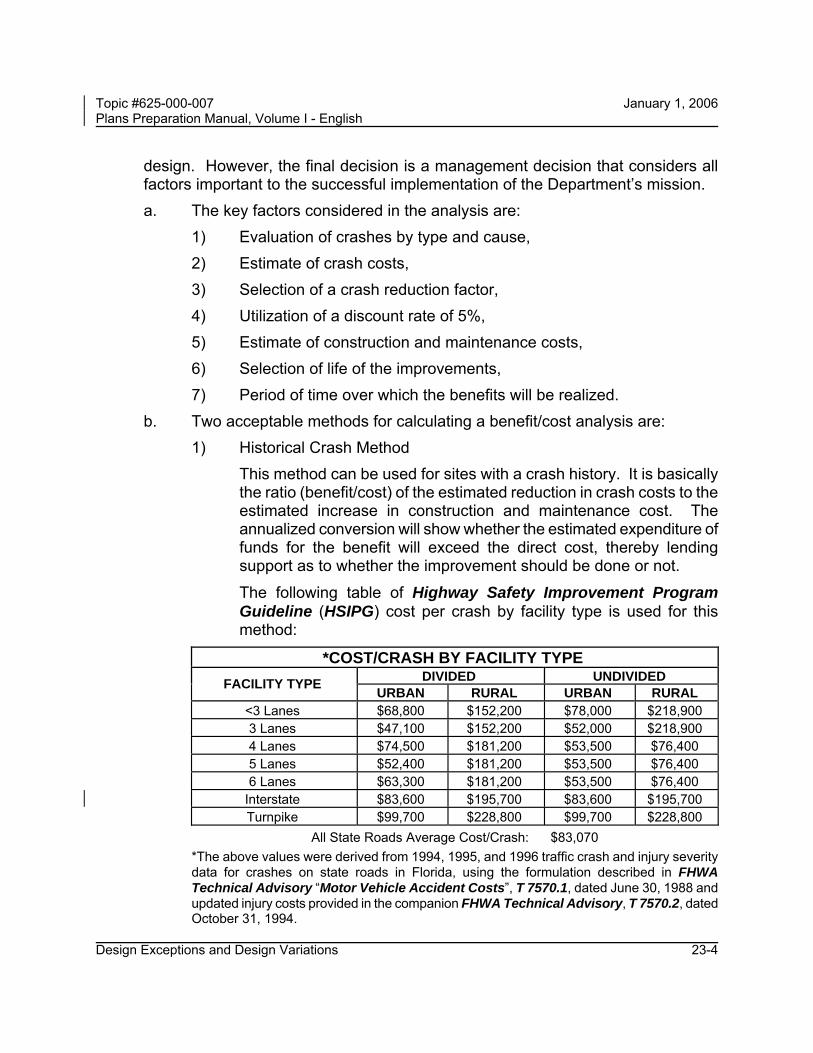
b. Two acceptable methods for calculating a benefit/cost analysis are: 1) Historical Crash Method This method can be used for sites with a crash history. It is basically
the ratio (benefit/cost) of the estimated reduction in crash costs to the estimated increase in construction and maintenance cost. The annualized conversion will show whether the estimated expenditure of funds for the benefit will exceed the direct cost, thereby lending support as to whether the improvement should be done or not.
The following table of Highway Safety Improvement Program Guideline (HSIPG) cost per crash by facility type is used for this method:
*COST/CRASH BY FACILITY TYPE DIVIDED UNDIVIDED FACILITY TYPE URBAN RURAL URBAN RURAL
<3 Lanes $68,800 $152,200 $78,000 $218,900 3 Lanes $47,100 $152,200 $52,000 $218,900 4 Lanes $74,500 $181,200 $53,500 $76,400 5 Lanes $52,400 $181,200 $53,500 $76,400 6 Lanes $63,300 $181,200 $53,500 $76,400
Interstate $83,600 $195,700 $83,600 $195,700 Turnpike $99,700 $228,800 $99,700 $228,800
All State Roads Average Cost/Crash: $83,070 *The above values were derived from 1994, 1995, and 1996 traffic crash and injury severity data for crashes on state roads in Florida, using the formulation described in FHWA Technical Advisory “Motor Vehicle Accident Costs”, T 7570.1, dated June 30, 1988 and updated injury costs provided in the companion FHWA Technical Advisory, T 7570.2, dated October 31, 1994.

Topic #625-000-007 January 1, 2006 Plans Preparation Manual, Volume I - English
Design Exceptions and Design Variations 23-5
2) ROADSIDE 5.0 computer program
This program complements the Roadside Design Guide dated January 1996. The program computer disks are normally furnished with the text.
This method can be used where clear zone applies. Based on the input (offsets, traffic, slopes, crash history, traffic accident severity levels, etc.) of information available to the user, the program will offer results which can be used in comparing courses of action. The current Roadside Design Guide and the FHWA Technical Advisory titled Motor Vehicle Accident Costs and dated October 31, 1994 provides guidance for the benefit/cost analysis.
Using this method for Department projects, the accident severity level costs to be used, noted in the Roadside Design Guide are revised as follows:
* Estimated Costs for Various Traffic Accident Severity Levels
Fatal Accident $2,600,000
Severe Injury Accident $505,000
Moderate Injury Accident $165,000
Slight Injury Accident $36,167
Property Damage Only Accident Level 2 $10,469
Property Damage Only Accident Level 1 $2,000
*The above values were derived from the FHWA Technical Advisory “Motor Vehicle Accident Costs”, T 7570.1, dated June 30, 1988 and updated injury costs provided in the companion FHWA Technical Advisory, T 7570.2, dated October 31, 1994.
5. Conclusions and Recommendations a. The cumulative effect of other deviations from design criteria, b. Safety mitigating measures considered and provided, c. Summarize specific course of action (Include conditional requirements such
as projects in the work program that will fix deficiency).

Topic #625-000-007 January 1, 2006 Plans Preparation Manual, Volume I - English
Design Exceptions and Design Variations 23-6
23.2.3 Approval and Concurrence
Design Exceptions on projects having full federal oversight (see Chapter 24 of this volume) and involvement are recommended by the District Design Engineer for approval by the FHWA Division Administrator.
Any Design Exception that reduces vertical clearance over an interstate roadway to less than 16 feet requires FHWA to coordinate with Military Traffic Management Command (MTMC) before the District Design Engineer can recommend the Design Exception.
Any Design Exception for design speed on the FIHS system shall require concurrence from the State Highway Engineer. All other Design Exceptions require concurrence from the State Roadway Design Engineer.
Design Exceptions impacting a structure require concurrence from the State Structures Design Engineer and the State Roadway Design Engineer.
All other projects are recommended by the Responsible Professional Engineer for approval by the District Design Engineer and concurrence by the State Roadway Design Engineer.
23.2.4 Sealing
All Design Exceptions are to be sealed in accordance with Chapter 19 of this volume.
23.2.5 Concurrence Review
After the documentation justifying the Design Exception is forwarded to the appropriate Area Design Engineer, the Design Exception will be reviewed for completeness and adherence to the requirements of this chapter.
If the Design Exception complies with all requirements, it will be signed by the appropriate engineer(s), signifying concurrence. When necessary, the Design Exception will be forwarded by the appropriate Area Design Engineer to FHWA for approval.
Topic #625-000-007 January 1, 2006 Plans Preparation Manual, Volume I - English
Design Exceptions and Design Variations 23-7
23.2.6 Copies and Distribution
One (1) original is required by the State Roadway Design Engineer’s Office (appropriate Area Design Engineer). Subsequent to obtaining all appropriate signatures for concurrence the following distribution is made: 1. The State Roadway Design Engineer’s Office will return one (1) signed original to
the District Design Engineer for files. 2. State Roadway Design Engineer’s Office will return one (1) copy of the signed
original to the District Design Engineer for submission to the Engineer of Record. 3. State Roadway Design Engineer’s Office will retain one (1) copy of the signed
original. 4. State Structures Design Engineer’s Office will retain one (1) copy of the signed
original for structure related Design Exceptions.
Topic #625-000-007 January 1, 2006 Plans Preparation Manual, Volume I - English
Design Exceptions and Design Variations 23-8
23.3 Design Variations
Design Variations are required when deviations from the Department’s criteria occur. However, when both AASHTO and Department criteria for any of the 13 Critical Design Elements are not met, a Design Exception will be processed in lieu of a Design Variation.
A Design Variation request must address the following items: 1. Design criteria versus proposed criteria. 2. Reason the design criteria are not appropriate. 3. Justification for the proposed criteria. 4. Any background information which documents or justifies the request.
Requests begin with the Responsible Professional Engineer and are submitted to the District Design Engineer for approval. This approval shall be documented in the project file as per the sample request letter Exhibit 23-B.
Any Design Variation for design speed on the FIHS system shall require concurrence from the State Highway Engineer.
Issues impacting a structure require final concurrence from the District Structures Design Engineer for Category 1 structures or the State Structures Design Engineer for all other structures.
As with Design Exceptions, it is critical that Design Variations be identified early in the process in order to allow time to research alternatives and begin the analysis and documentation activities. This is preferably done during the PD&E process for major projects and the scope development process for minor projects. It is required that approval be obtained no later than the initial engineering phase.
All Design Variations are to be sealed in accordance with Chapter 19 of this volume.
The District Design Engineer will retain the original and distribute one (1) signed copy to the Engineer of Record.

Topic #625-000-007 January 1, 2006 Plans Preparation Manual, Volume I - English
Design Exceptions and Design Variations 23-9
23.4 AASHTO Criteria for Critical Design Elements
As an aid to the designer, the following tables may be used as a reference for determining when a Design Exception is required based on AASHTO criteria, but are in no way intended to replace Department design criteria. The page numbers referenced are to AASHTO’s A Policy on Geometric Design of Highways and Streets 2001 and are a starting point for researching project criteria.
Criteria Tables Cross Reference Table Number
Title
Page
Table 23.4.1 AASHTO Design Speed (Minimum)........................................23-11
Table 23.4.2 AASHTO Lane Widths (Minimum) ..........................................23-12
Table 23.4.3 AASHTO Shoulder Widths (Minimum)...................................23-12
Table 23.4.4 AASHTO Bridge Widths (Minimum) .......................................23-13
Table 23.4.5 AASHTO Structural Capacity (Minimum Loadings)..............23-14
Table 23.4.6 AASHTO Vertical Clearance (Minimum) ................................23-14
Table 23.4.7 AASHTO Grades (Minimum and Maximum) ..........................23-15
Table 23.4.8 AASHTO Cross Slope (Minimum and Maximum)..................23-15
Table 23.4.9 AASHTO Superelevation (Maximum) .....................................23-16
Table 23.4.10 AASHTO Horizontal Alignment...............................................23-16
Table 23.4.11 AASHTO Vertical Alignment ...................................................23-17
Table 23.4.12 AASHTO Stopping Sight Distance .........................................23-17
Table 23.4.13 AASHTO Horizontal Clearance (Minimum)............................23-18 NOTE: AASHTO’s A Policy on Geometric Design of Highways and Streets 2004 may be used instead of the 2001 edition. The 2004 edition is in substantial conformance with the criteria in the 2001 edition, so use of either edition is acceptable. The major change in the 2004 edition is a revision of the superelevation section which resulted in minor differences in superelevation rates. The AASHTO page numbers referenced in this chapter only apply to the 2001 edition and may not correspond to the correct page numbers in the 2004 edition.

Topic #625-000-007 January 1, 2006 Plans Preparation Manual, Volume I - English
Design Exceptions and Design Variations 23-10
THIS PAGE LEFT BLANK INTENTIONALLY

Topic #625-000-007 January 1, 2006 Plans Preparation Manual, Volume I - English
Design Exceptions and Design Variations 23-11
Table 23.4.1 AASHTO Design Speed (Minimum) Type Facility Other Factors Design Speed (mph) AASHTO
Freeways Urban Rural
50 70
pg. 507
Urban Arterials Major Other
30 30
pg. 72
Rural Arterials Rolling terrain Level terrain
50 60
pg. 448
Urban Collectors 30 pg. 434 Rural Collectors Level ADT < 400
ADT 400 - 2000 ADT > 2000 Rolling ADT < 400 ADT 400 - 2000 ADT > 2000
40 50 60
30 40 50
pg. 426, Exh. 6-2
CBD Major or Minor 30 pg. 434 Ramps Highway Design Speeds (mph)
30 35 40 45 50 55 60 65 70
15 18 20 23 25 28 30 30 35
pg. 830
Loop Ramps 150 ft. radius 25 pg. 829 Connections Direct
Semi-Direct 40 30
pg. 829
Topic #625-000-007 January 1, 2006 Plans Preparation Manual, Volume I - English
Design Exceptions and Design Variations 23-12
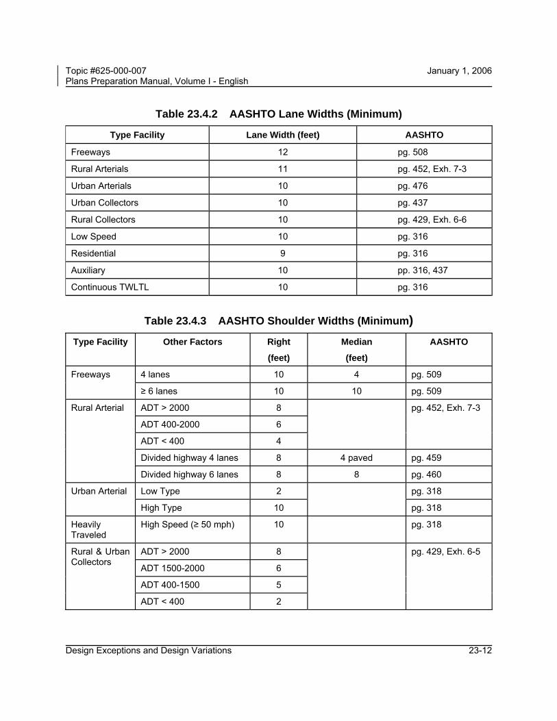
Table 23.4.2 AASHTO Lane Widths (Minimum)
Type Facility Lane Width (feet) AASHTO
Freeways 12 pg. 508
Rural Arterials 11 pg. 452, Exh. 7-3
Urban Arterials 10 pg. 476
Urban Collectors 10 pg. 437
Rural Collectors 10 pg. 429, Exh. 6-6
Low Speed 10 pg. 316
Residential 9 pg. 316
Auxiliary 10 pp. 316, 437
Continuous TWLTL 10 pg. 316
Table 23.4.3 AASHTO Shoulder Widths (Minimum) Type Facility Other Factors Right
(feet)
Median
(feet)
AASHTO
4 lanes 10 4 pg. 509 Freeways
≥ 6 lanes 10 10 pg. 509
ADT > 2000 8
ADT 400-2000 6
ADT < 400 4
pg. 452, Exh. 7-3
Divided highway 4 lanes 8 4 paved pg. 459
Rural Arterial
Divided highway 6 lanes 8 8 pg. 460
Low Type 2 pg. 318 Urban Arterial
High Type 10
pg. 318
Heavily Traveled
High Speed (≥ 50 mph) 10 pg. 318
ADT > 2000 8
ADT 1500-2000 6
ADT 400-1500 5
Rural & Urban Collectors
ADT < 400 2
pg. 429, Exh. 6-5

Topic #625-000-007 January 1, 2006 Plans Preparation Manual, Volume I - English
Design Exceptions and Design Variations 23-13
Table 23.4.4 AASHTO Bridge Widths (Minimum) Type
Facility Other Factors Bridge Widths AASHTO
Freeways New Bridges Approach Roadway Width pg. 510
New Bridges (Short) Approach Roadway Width pg. 451
New Long Bridges (> 200 ft.)
Travel Lanes + 4 ft. each side pg. 451
Rural Arterials
Remain in Place Travel Lanes + 2 ft. each side pg. 451
Long (> 200 ft.), where shoulders or parking lanes are provided on the arterial
Travel Lanes + 4 ft. each side pg. 485 Urban Arterials
All new bridges Curb to curb width of street pg. 485
Bridge Widths
Type Facility Other Factors New or Reconstruction To
Remain AASHTO
Under 400 ADT Traveled Way + 2 ft. each side (1) 22 ft. (2) pp. 430, 431
ADT 400-1500 Traveled Way + 3 ft. each side (1) 22 ft. (2) pp. 430, 431
ADT 1500-2000 Traveled Way + 4 ft. each side(1),(3) 24 ft. (2) pp. 430, 431
Rural and Urban Collectors
ADT > 2000 Approach Roadway Width (1),(3) 28 ft. (2) pp. 430, 431
1. If the approach roadway has paved shoulders, then the surfaced width shall be carried across the bridge.
2. Bridges longer than 100 ft. are to be analyzed individually. 3. For bridges > 100 ft. in length, the minimum bridge width of traveled way plus 3 ft. on each side is
acceptable.

Topic #625-000-007 January 1, 2006 Plans Preparation Manual, Volume I - English
Design Exceptions and Design Variations 23-14
Table 23.4.5 AASHTO Structural Capacity (Minimum Loadings)
Type Facility Other Factors Loading AASHTO
Freeways --- HS-20 pg. 510
Rural Arterials --- HS-20 pg. 451
Urban Arterials --- HS-20 pg. 451
New & Reconstruction Bridges HS-20 pg. 390, Exh. 5-6 Local Roads
Existing Bridges H 15 pg. 390, Exh. 5-7
New & Reconstruction Bridges HS-20 pg. 430, Exh. 6-6 Collectors
Existing Bridges H 15 pg. 431, Exh. 6-7
Table 23.4.6 AASHTO Vertical Clearance (Minimum)
Type Facility Vertical Clearance (feet) AASHTO
Freeways 16 (1),(2) pp. 510, 511, 767, 768
Arterials: Rural Urban
16 (1),(2) 16 (1),(2)
pp. 451, 767, 768 476, 767, 768
Other Highways 14 (2) pp. 389, 511
Sign Trusses 17 (2) pg. 511
Pedestrian Overpass 17 (2) pg. 511
Tunnels: Freeways Other Highways
16 (2) 14 (2)
pg. 359 pg. 359
Railroads 23 (2) pg. 526
1. 14 feet allowed in highly developed urban areas if alternate route has 16 feet. 2. Minimum value that can be used without a Design Exception. An allowance of 6 inches should be
added to vertical clearance to accommodate future resurfacing.
Topic #625-000-007 January 1, 2006 Plans Preparation Manual, Volume I - English
Design Exceptions and Design Variations 23-15
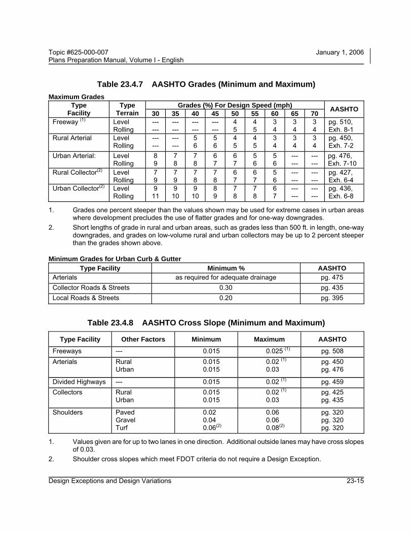
Table 23.4.7 AASHTO Grades (Minimum and Maximum) Maximum Grades
Grades (%) For Design Speed (mph) Type Facility
Type Terrain 30 35 40 45 50 55 60 65 70 AASHTO
Freeway (1) Level Rolling
--- ---
--- ---
--- ---
--- ---
4 5
4 5
3 4
3 4
3 4
pg. 510, Exh. 8-1
Rural Arterial Level Rolling
--- ---
--- ---
5 6
5 6
4 5
4 5
3 4
3 4
3 4
pg. 450, Exh. 7-2
Urban Arterial: Level Rolling
8 9
7 8
7 8
6 7
6 7
5 6
5 6
--- ---
--- ---
pg. 476, Exh. 7-10
Rural Collector(2) Level Rolling
7 9
7 9
7 8
7 8
6 7
6 7
5 6
--- ---
--- ---
pg. 427, Exh. 6-4
Urban Collector(2) Level Rolling
9 11
9 10
9 10
8 9
7 8
7 8
6 7
--- ---
--- ---
pg. 436, Exh. 6-8
1. Grades one percent steeper than the values shown may be used for extreme cases in urban areas where development precludes the use of flatter grades and for one-way downgrades.
2. Short lengths of grade in rural and urban areas, such as grades less than 500 ft. in length, one-way downgrades, and grades on low-volume rural and urban collectors may be up to 2 percent steeper than the grades shown above.
Minimum Grades for Urban Curb & Gutter Type Facility Minimum % AASHTO
Arterials as required for adequate drainage pg. 475 Collector Roads & Streets 0.30 pg. 435 Local Roads & Streets 0.20 pg. 395
Table 23.4.8 AASHTO Cross Slope (Minimum and Maximum)
Type Facility Other Factors Minimum Maximum AASHTO
Freeways --- 0.015 0.025 (1) pg. 508 Arterials Rural
Urban 0.015 0.015
0.02 (1) 0.03
pg. 450 pg. 476
Divided Highways --- 0.015 0.02 (1) pg. 459 Collectors Rural
Urban 0.015 0.015
0.02 (1) 0.03
pg. 425 pg. 435
Shoulders Paved Gravel Turf
0.02 0.04 0.06(2)
0.06 0.06 0.08(2)
pg. 320 pg. 320 pg. 320
1. Values given are for up to two lanes in one direction. Additional outside lanes may have cross slopes of 0.03.
2. Shoulder cross slopes which meet FDOT criteria do not require a Design Exception.

Topic #625-000-007 January 1, 2006 Plans Preparation Manual, Volume I - English
Design Exceptions and Design Variations 23-16
Table 23.4.9 AASHTO Superelevation (Maximum) Type Facility Superelevation Rate AASHTO
Highways (Rural) 0.12 pg. 141 Urban 0.06 pg. 142 Low Speed Urban w/severe constraints None pg. 142 Ramps and Turning Roadways at Intersections 0.10 pg. 643
Table 23.4.10 AASHTO Horizontal Alignment
Minimum Radius (feet) with Superelevation (page 145, Exh. 3-14) Minimum Curve Radius (feet) for Design Speed (mph) Type
Facility Super-
elevation e-max 15 20 25 30 35 40 45 50 55 60 65 70 0.04 70 125 205 300 420 565 730 930 1190 1505 --- --- 0.06 65 115 185 275 380 510 660 835 1065 1340 1660 20500.08 60 105 170 250 350 465 600 760 965 1205 1485 18200.10 55 100 160 230 320 430 555 695 880 1095 1345 1640
Rural Highways and High Speed Urban Streets 0.12 50 90 145 215 300 395 510 645 810 1005 1230 1490
Minimum Radius (feet) for Section with Normal Cross Slope (page 168, Exh. 3-26) Minimum Curve Radius (feet) for Design Speed (mph) Type
Facility 15 20 25 30 35 40 45 50 55 60 65 70
All 960 1700 2460 3350 4390 5570 6880 8350 9960 11720 13180 14730
Minimum Radius (feet) for Intersection Curves (page 201, Exh. 3-43) Design Speed
(MPH) 10 15 20 25 30 35 40 45
Minimum Radius (feet) 25 50 90 150 230 310 430 540
Assumed Minimum Superelevation Rate 0.02 0.02 0.02 0.04 0.06 0.08 0.09 0.10
Minimum Passing Sight Distance (feet) (page 124, Exh. 3-7) Design Speed
(mph) 20 25 30 35 40 45 50 55 60 65 70
Passing Sight Distance 710 900 1090 1280 1470 1625 1835 1985 2135 2285 2480
Topic #625-000-007 January 1, 2006 Plans Preparation Manual, Volume I - English
Design Exceptions and Design Variations 23-17
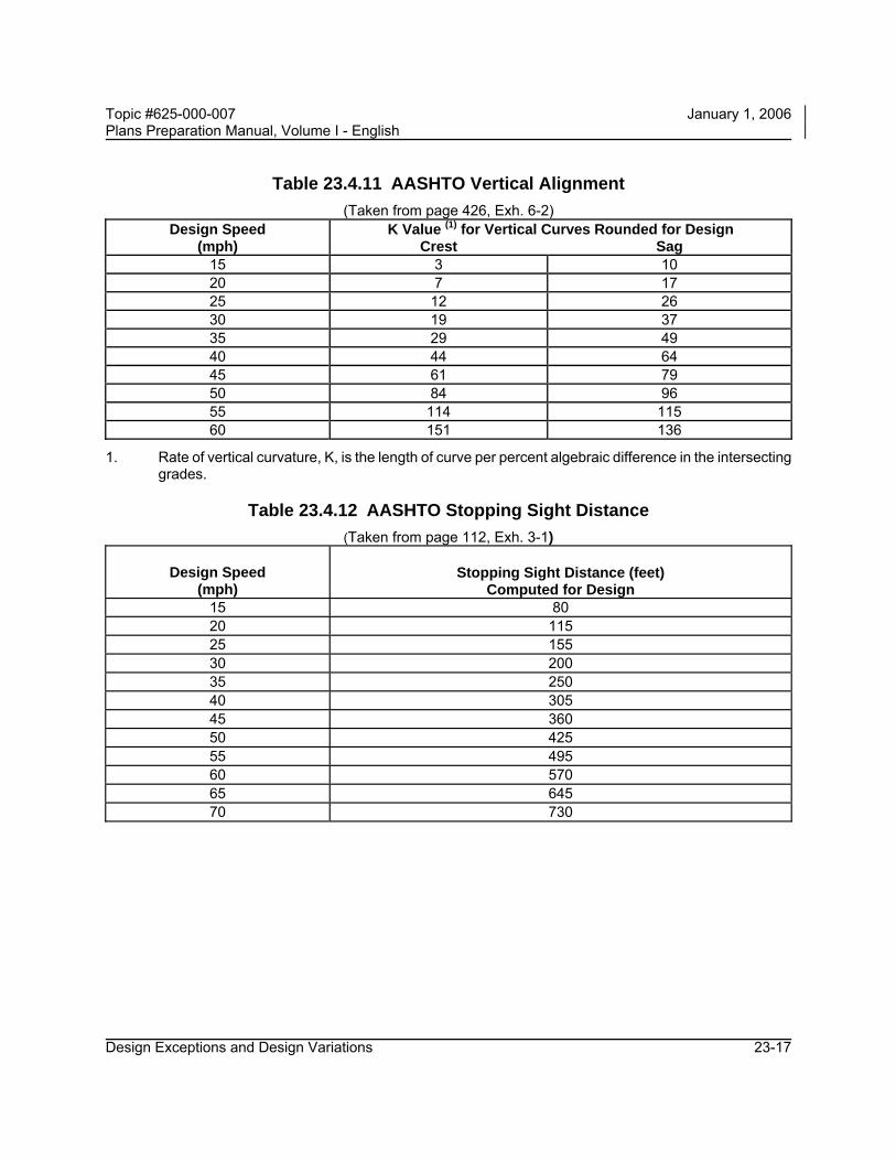
Table 23.4.11 AASHTO Vertical Alignment
(Taken from page 426, Exh. 6-2) Design Speed
(mph) K Value (1) for Vertical Curves Rounded for Design
Crest Sag 15 3 10 20 7 17 25 12 26 30 19 37 35 29 49 40 44 64 45 61 79 50 84 96 55 114 115 60 151 136
1. Rate of vertical curvature, K, is the length of curve per percent algebraic difference in the intersecting grades.
Table 23.4.12 AASHTO Stopping Sight Distance
(Taken from page 112, Exh. 3-1)
Design Speed (mph)
Stopping Sight Distance (feet)
Computed for Design 15 80 20 115 25 155 30 200 35 250 40 305 45 360 50 425 55 495 60 570 65 645 70 730

Topic #625-000-007 January 1, 2006 Plans Preparation Manual, Volume I - English
Design Exceptions and Design Variations 23-18
Table 23.4.13 AASHTO Horizontal Clearance (Minimum) Feature Clearance AASHTO
Bridges See Table 23.4.4 ---
Tunnels 2.5 ft. from edge of traffic lane pg. 358
Underpasses 2-lane: Normal shoulder width (to edge of barrier) (1) Divided Roadway: Normal shoulder (outside or median) width
(to edge of barrier) (1)
pg. 766, Exh. 10-6
Barrier Wall & Guardrail
Normal shoulder width pg. 766, Exh. 10-6
Light Poles (2) Rural: Outside clear zone (if non-breakaway) Urban: 1.5 ft. from face of curb
pg. 295 pg. 323
Trees greater than 4 inches in diameter measured 6 inches above the ground
Rural Arterials: Outside clear zone Collectors ≤ 45 mph: 10 ft. from traveled way Collectors > 45 mph: Outside clear zone Urban: 1.5 ft. from face of curb Freeways (Rural and Urban): Outside clear zone
pg. 403, 485 pg. 431 pg. 431 pg. 403,441,485 pg. 511
Sign supports Outside clear zone (if non-breakaway) pg. 299
Utility Poles (2) Rural: Outside clear zone Urban: 1.5 ft. from face of curb
pg. 298 pp. 297, 323
Building Line 15 feet from elevated roadway (wall) pg. 526
Signal Pole and Controller Cabinets
Rural: As far from the roadway as practicable Urban: 1.5 ft. from face of curb
pg. 4-13 (3)
pg. 323
1. For metal guardrail, add deflection distance. 2. Exceptions for utility poles are to be in accordance with the current Utility Accommodation Manual
exceptions procedure for horizontal clearance for utility poles. 3. AASHTO Roadside Design Guide.

Topic #625-000-007 January 1, 2006 Plans Preparation Manual, Volume I - English
Design Exceptions and Design Variations 23-19
Exhibit 23-A Sample Request Letter for Design Exception To:(1) , Date: Subject: Design Exception Financial Project ID: County Section Number: State Road Number: Federal Aid Number: Project Description: Begin Project MP: . End Project MP: . New Construction RRR Plans Phase: PD&E ___ I ___ II ___ III ___ IV ___ Federal Oversight: Yes No
A design exception is requested for the following element(s): ( ) Design Speed (4) ( ) Lane Widths ( ) Shoulder Widths ( ) Bridge Widths ( ) Structural Capacity ( ) Vertical Clearance ( ) Grades ( ) Cross Slope ( ) Superelevation ( ) Horizontal Alignment ( ) Vertical Alignment ( ) Stopping Sight Distance ( ) Horizontal Clearance Include a brief statement concerning the project and items of concern. Attach all supporting documentation to this exhibit in accordance with Section 23.2 including crash history and plans identifying crash locations. Prepared by (2): Recommended by: Responsible Professional Engineer (print or type)
Date / / Consultant Firm (print or type)
Recommended by (2): Approved by (3): Date / / District Design Engineer Concurrence (4): Date / / State Roadway Design Engineer Concurrence (5): Date / / State Structures Design Engineer Approved by (3): Date / / FHWA Division Administrator Concurrence (4): Date / / State Highway Engineer
1. Design exceptions on projects having full federal oversight and involvement are addressed to the FHWA Division Administrator. All other design exceptions are addressed to the District Design Engineer.
2. Design exceptions on projects having full federal oversight and involvement are recommended by the District Design Engineer and prepared by the Responsible Professional Engineer. All other design exceptions are recommended by the Responsible Professional Engineer.
3. Design exceptions on projects having full federal oversight and involvement are approved by the FHWA Division Administrator. All other design exceptions are approved by the District Design Engineer.
4. Design exceptions for design speed on the FIHS requires concurrence from the State Highway Engineer following a review with the State Transportation Planner. All other design exceptions require concurrence from the State Roadway Design Engineer.
5. Design exceptions impacting the geometry, vertical clearance, layout of structures, or superstructure cross slope require concurrence from the State Structures Design.
Topic #625-000-007 January 1, 2006 Plans Preparation Manual, Volume I - English
Design Exceptions and Design Variations 23-20
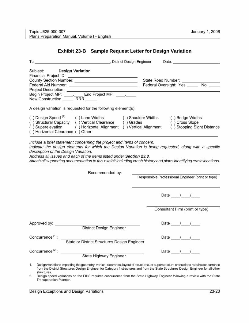
Exhibit 23-B Sample Request Letter for Design Variation
To: , District Design Engineer Date: Subject: Design Variation Financial Project ID: County Section Number: State Road Number: Federal Aid Number: Federal Oversight: Yes No Project Description: Begin Project MP: . End Project MP: . New Construction RRR A design variation is requested for the following element(s): ( ) Design Speed (2) ( ) Lane Widths ( ) Shoulder Widths ( ) Bridge Widths ( ) Structural Capacity ( ) Vertical Clearance ( ) Grades ( ) Cross Slope ( ) Superelevation ( ) Horizontal Alignment ( ) Vertical Alignment ( ) Stopping Sight Distance ( ) Horizontal Clearance ( ) Other Include a brief statement concerning the project and items of concern. Indicate the design elements for which the Design Variation is being requested, along with a specific description of the Design Variation. Address all issues and each of the Items listed under Section 23.3. Attach all supporting documentation to this exhibit including crash history and plans identifying crash locations.
Recommended by: Responsible Professional Engineer (print or type) Date ____/____/____ Consultant Firm (print or type) Approved by: Date ____/____/____ District Design Engineer Concurrence (1) : Date ____/____/____ State or District Structures Design Engineer Concurrence (2) : Date ____/____/____ State Highway Engineer 1. Design variations impacting the geometry, vertical clearance, layout of structures, or superstructure cross slope require concurrence
from the District Structures Design Engineer for Category 1 structures and from the State Structures Design Engineer for all other structures.
2. Design speed variations on the FIHS requires concurrence from the State Highway Engineer following a review with the State Transportation Planner.

Topic #625-000-007 January 1, 2006 Plans Preparation Manual, Volume I - English
Design Exceptions and Design Variations 23-21
Exhibit 23-C Design Exceptions Variations and Utility Exceptions Process
GOVERNING CRITERIA(1) For all new construction, reconstruction and RRR
interstate projects, FDOT's standard criteria inChapter 2 or FIHS criteria in Chapter 1 of thisvolume governs.
(2) For RRR projects (except interstate), RRR criteriain Chapter 25 of this volume governs*.
(3) F o r T r a n s p o r t a t i o n D e s i g n s f o r L i v a b l eCommunities (TDLC), Chapter 21 of this volumegoverns.
(4) For Utility Exceptions, Chapters 5 & 9 in the UtilityAccommodation Manual governs.
YESNO
NO
Document the justification.(Section 23.3 and Exhibit 23-B).
Coordinate alternatives withoffices giving approval and
concurrence. (Section 23.2).
YES
Element aCritical Design Element ?
(Section 23.2)
NO
YESProposed value
meets or exceeds Governing Criteria?
Proposedvalue meets or exceeds
AASHTO?*(Section 23.3)
Identify design element andproposed value.
Design VariationsDesign Exceptions
When approval is obtained,signed original is retained by the
District Design Engineer.(Section 23.3)
Identify the approval andconcurrence required.
(Section 23.2).
Document the justification.(Section 23.2 and Exhibit 23-A)
No Design Exception/Variationor Utility Exception required.
(Section 23.1)
NOTESReference Section 23.2* Where RRR criteria governs and is not met:
1. a Design Variation is required when AASHTO new construction criteria are met;
2. a Design Exception is required when AASHTO new construction criteria are not met.
Reference Section 23.2**For FHWA approved Design Exceptions, forward
the recommended Design Exception.
CRITICAL DESIGN ELEMENTS1. Design Speed 8. Cross Slope2. Lane Widths 9. Superelevation3. Shoulder Widths 10. Horizontal Alignment4. Bridge Widths 11. Vertical Alignment5. Structural Capacity 12. Stopping Sight Distance6. Vertical Clearance 13. Horizontal Clearance7. Grades
Identify Governing Criteria(1), (2), (3) or (4).
Forward the approved DesignException** for a concurrence
review. (Section 23.2)
Identify if structure'sconcurrence is required.
(Section 23.3).
If required, coordinate alternativeswith structures for concurrence.
(Section 23.3).
When concurrence is obtained,signed original will be returned to
the District Design Engineer.(Section 23.2)
UTILITY EXCEPTION TYPES1. Vertical Clearance of a Utility2. Horizontal Clearance of a Utility3. Limited Access Use by a Utility4. Control Zone Use by a Utility Process a Utility Exception in
accordance with Chapter 13 of theUtility Accommodation Manual.
YESUtility
Exception Typeissue?
NO

Topic #625-000-007 January 1, 2006 Plans Preparation Manual, Volume I - English
Design Exceptions and Design Variations 23-22
THIS PAGE LEFT BLANK INTENTIONALLY