Embed Size (px)
Citation preview

Chapter 23- Light: Geometric Optics

Changes in OfficeChanges in Office--hours hours
The following changes will take place until the end of the semester
Office-hours:
- Monday, 12:00-13:00h
- Wednesday, 14:00-15:00h
- Friday, 13:00-14:00h

Old assignments and midterm exams
(solutions have been posted on
the web)
can be picked up in my office
(LB-212)

All marks, including assignments, have
been posted on the web.
http://ilc2.phys.uregina.ca/~barbi/academic/phys109/marks.pdfhttp://ilc2.phys.uregina.ca/~barbi/academic/phys109/marks.pdf
Please, verify that all your marks have
been entered in the list.

Chapter 23
• The Ray Model of Light
• Reflection; Image Formed by a Plane Mirror
• Formation of Images by Spherical Mirrors
• Index of Refraction
• Refraction: Snell’s Law
• Total Internal Reflection; Fiber Optics
• Thin Lenses; Ray Tracing
• The Thin Lens Equation; Magnification
• Lensmaker’s Equation

Recalling Recalling LastLast LecturesLecturesRecalling Recalling LastLast LecturesLectures

The Conditions for EquilibriumThe Conditions for Equilibrium
First condition of equilibrium
� No change in translational motion
The first condition for equilibrium is that the forces
along each coordinate axis add to zero.
(9-1)
The Conditions for EquilibriumThe Conditions for Equilibrium
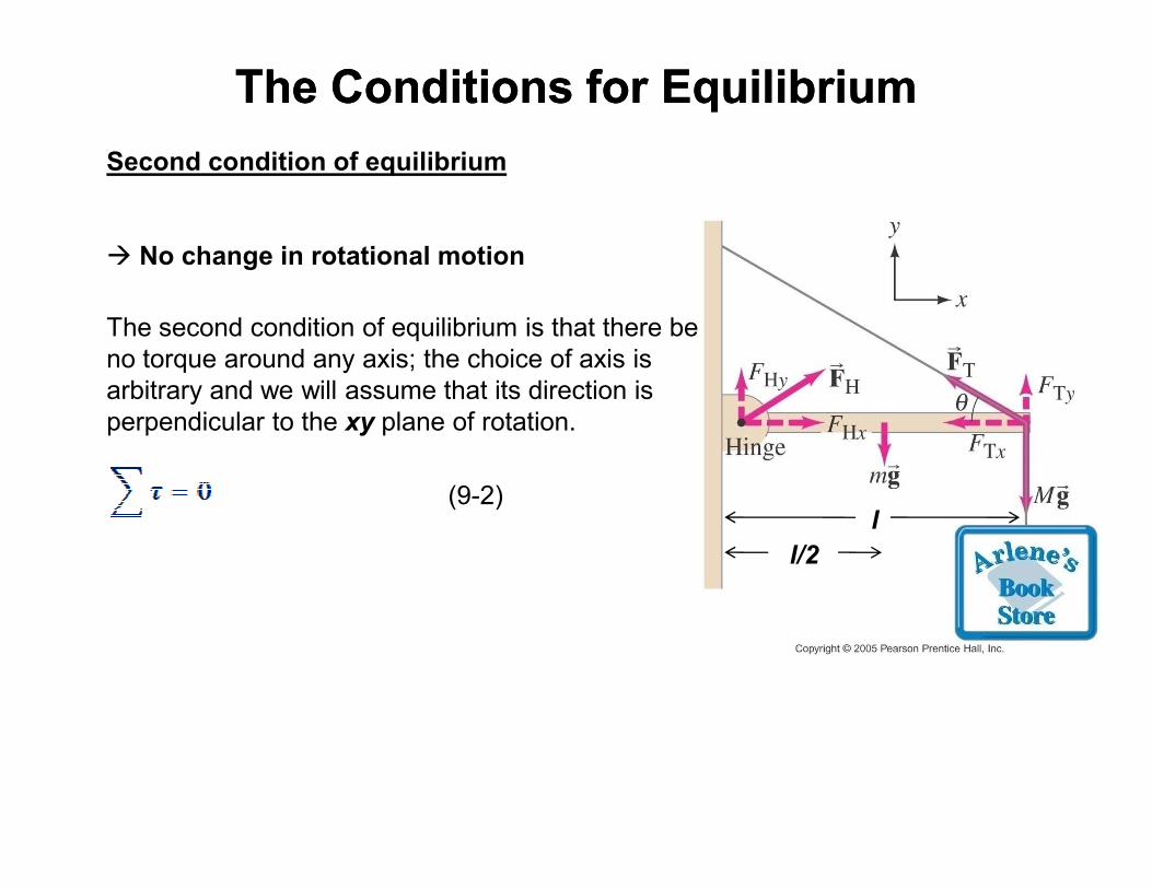
Second condition of equilibrium
� No change in rotational motion
The second condition of equilibrium is that there be
no torque around any axis; the choice of axis is
arbitrary and we will assume that its direction is
perpendicular to the xy plane of rotation.
(9-2)l
l/2

The Conditions for EquilibriumThe Conditions for Equilibrium
Recalling an important note:
We consider that the mass of an object with
uniform mass distribution (or uniform object for
short) is such that it can be assumed to be
located at the center of the object.
This point is know as either center of mass or
center of gravity of the object.center of gravity of the object.
l
l/2
For an uniform sphere, its center of mass is located in its center.

Solving Statics ProblemsSolving Statics Problems1. Choose one object at a time, and make a free-body diagram showing all the
forces on it and where they act.
2. Choose a coordinate system and resolve forces into components.
3. Write equilibrium equations for the forces.
4. Choose any axis perpendicular to the plane of the forces and write the torque 4. Choose any axis perpendicular to the plane of the forces and write the torque
equilibrium equation. A clever choice here can simplify the problem
enormously.
5. Make sure you correctly identify the components of the forces that can
contribute to rotational motion. Forces that have zero lever arm do not
contribute to rotational motion.
6. Solve.

TodayTodayTodayToday

Problem 9-1 (textbook): Three forces are applied to a tree sapling, as shown in
Fig. 9–41, to stabilize it. If and , find in magnitude and
direction.

Problem 9-1 :
If the tree is not accelerating, then the net force in all
directions is 0.
( )
A B C
C A B
cos110 0
cos110 310 N 425 N cos110 164.6 N
sin 0
x x
x
F F F F
F F F
F F F
= + + = →
= − − = − − = −
= + = →
∑
∑
And so is 430 N, at an angle of 112o clockwise from .
( )
B C
C B
sin 0
sin110 425 N sin110 399.4 N
y y
y
F F F
F F
= + = →
= − = − = −
∑
( ) ( )2 22 2 2
C C C
C1 1 o o o o o
C
164.6 N 399.4 N 432.0 N 4.3 10 N
399.4 Ntan tan 67.6 , 180 67.6 112.4 112
164.6 N
x y
y
x
F F F
F
Fθ φ− −
= + = − + − = ≈ ×
−= = = = − = ≈
−

Problem 9-27 (textbook): Consider a ladder with a painter climbing up it (Fig. 9–
61). If the mass of the ladder is 12.0 kg, the mass of the painter is 55.0 kg, and the
ladder begins to slip at its base when her feet are 70% of the way up the length of the
ladder, what is the coefficient of static friction between the ladder and the floor?
Assume the wall is frictionless.

Problem 9-27:
The ladder is in equilibrium, so the net torque and net force must be zero.
By stating that the ladder is on the verge of slipping, the static frictional force at the
ground, , is at its maximum value and so:C xF
C Cx s yF Fµ=
Since the person is standing 70% of the way up Since the person is standing 70% of the way up
the ladder, the height of the ladder is:
The width of the ladder is:
0.7 2.8 m 0.7 4.0 my yL d= = =
0.7 2.1 m 0.7 3.0 mx xL d= = =

Problem 9-27
Torques are taken about the point of contact of the ladder
with the ground, and counterclockwise torques are taken
as positive. The three conditions of equilibrium are as follows:
C W C W0
x x xF F F F F= − = → =∑
G0
y yF F Mg mg= − − = →∑( ) ( )( )
( )
G
2
G
1
W 2
67.0 kg 9.80 m s 656.6 N
0
y y
y
y x x
F M m g
F L mg L Mgdτ
= + = =
= − − =
∑
∑
Solving the torque equation gives:
( )( ) ( )( )( )
11222
W
12.0 kg 3.0 m 55.0 kg 2.1 m9.80m s 327.1 N
4.0 m
x x
y
mL MdF g
L
++= = =
The coefficient of friction then is found to beG
G
327.1 N0.50
656.6 N
x
s
y
F
Fµ = = =

The Ray Model of LightThe Ray Model of Light
Light is a form of electromagnetic wave.
• It has electric and magnetic components and propagates according to the
properties of wave
Visible light is a form of electromagnetic wave with wavelength in the so called
visible region of the light spectrum
In fact, light sometimes also behaves as particle � come to my Phys-242 classes
and you will understand some of the particle-like properties of light and how it
changed our perception of the Universe.

The Ray Model of LightThe Ray Model of Light
How do we see objects:
• An object can be a source o light such as stars, candles, etc.
• An object might reflect the light produced by some light source.
In either cases, the light will travel from the object to your eyes.
In this chapter we will assume that light travels in straight paths.
� We represent light using rays which are straight lines emanating from an object.
� This is an idealization, but is very useful for
our purposes.
It is therefore important to understand how light
reflects on objects in order to understand how
we see the world
Since we will be dealing with straight-line rays at various
angles, we call this area geometric optics.

Reflection; Image Formation by a Plane MirrorReflection; Image Formation by a Plane Mirror
Given that one way of observing objects is by light reflection, let’s spend the next
few slides discussing on it.
As light strikes on an object, the following processes can take place:
• Some or all of the light can be reflected
• Some or all of the light can be absorbed (for example, transformed into
thermal energy)thermal energy)
• If the object is transparent (for example, glass or water), some or all of the
light can be transmitted through the object
Reflection; Image Formation by a Plane MirrorReflection; Image Formation by a Plane Mirror
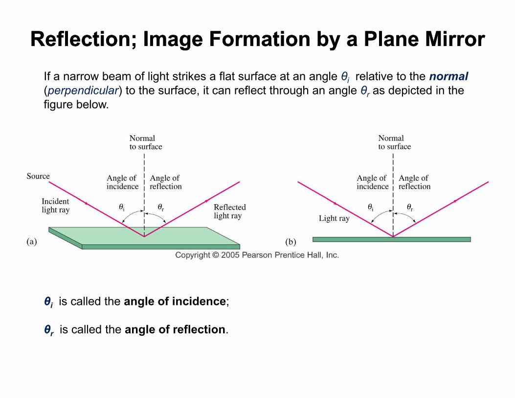
If a narrow beam of light strikes a flat surface at an angle θi relative to the normal
(perpendicular) to the surface, it can reflect through an angle θr as depicted in the
figure below.
θi is called the angle of incidence;
θr is called the angle of reflection.

Reflection; Image Formation by a Plane MirrorReflection; Image Formation by a Plane Mirror
It is found that θi and θr both lie in the same plane with the normal to the surface,
and that:
Eq. 23-1 is known as Law of Reflection.
(23-1)

Reflection; Image Formation by a Plane MirrorReflection; Image Formation by a Plane Mirror
When parallel rays of light reflects from a rough surface, the law of reflection
still holds, but the angles of incidence vary. This is called diffuse reflection.
normal(1)
normal(2)
normal(3)
What happens is that the normal is defined relative to the surface. Depending
where the ray of light strikes the surface, the normal will be pointing to different
directions.
On the other hand, when parallel rays of light reflects on a flat smooth surface, the
angle of incidences do not vary. This is called specular reflection.
normal(1)

Reflection; Image Formation by a Plane MirrorReflection; Image Formation by a Plane Mirror
The effect of diffuse reflection is that an object can be see at different angles by the
light reflect from it.
With specular reflection (from a mirror), your eye must be in the correct position,
otherwise you do not see the object.

Reflection; Image Formation by a Plane MirrorReflection; Image Formation by a Plane Mirror
What you see when you look into a plane (flat) mirror is an image, which appears
to be behind the mirror.
You have the perception that the object (or
you) is represented by an image that
reflects the correct dimensions of the
object and appears to be at a distance
“behind” the mirror that corresponds to that
real distance between the object and the
surface of the mirror.
But how does it work?

Reflection; Image Formation by a Plane MirrorReflection; Image Formation by a Plane Mirror
Let consider the object in the figure (a bottle of something).
Light will be reflected at any point
on the bottle surface that is
illuminated by some beam of light.
Let’s consider two points: the top and
bottom of the bottle.
Light rays will leave each of these
points (and any other point to this
matter) at different angles.
Let’s consider two of such rays leaving each point as shown in the figure such
that they represent the threshold angles between which any other ray will arrive
at an observer’s eye after reflecting on the mirror.
Each set of rays leaving a point on the bottle and reflecting on the mirror will be
seem by the observer as coming from a single point as shown in the figure.

Reflection; Image Formation by a Plane MirrorReflection; Image Formation by a Plane Mirror
What happen is the following:
Consider point A on the object.
Each of the two rays will leave
this point and strike the mirror at
points B and B’ as shown in the points B and B’ as shown in the
figure.
They will reflect following the law
of reflection.
For instance, at point B the ray
will have angle of incidence θi and
reflection θr such that:
Reflection; Image Formation by a Plane MirrorReflection; Image Formation by a Plane Mirror
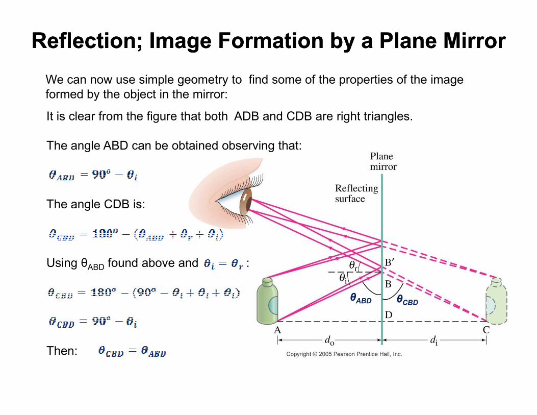
We can now use simple geometry to find some of the properties of the image
formed by the object in the mirror:
It is clear from the figure that both ADB and CDB are right triangles.
The angle ABD can be obtained observing that:
The angle CDB is:The angle CDB is:
Using θABD found above and :
Then:
θABD θCBD

Reflection; Image Formation by a Plane MirrorReflection; Image Formation by a Plane Mirror
The equality above tell me that the image distance di is equal to the object
distance do.
It is not difficult to show that
the height of the object
You think you are
seeing light
travelling in a
straight path from the height of the object
doesn’t change.
θABD θCBD
This basic explains why we see the
image the way it is!
The image formed “behind” the mirror
is called virtual image opposed to
real image in which the image is
formed on the same side of the
mirror where the real object is located
(we will come back to this in few slides)
straight path from
the image

Reflection; Image Formation by a Plane MirrorReflection; Image Formation by a Plane Mirror
Example 23-3 (textbook): Two mirrors meet at a 135° angle, Fig. 23–47. If light
rays strike one mirror at 40° as shown, at what angle φ do they leave the second
mirror?

Reflection; Image Formation by a Plane MirrorReflection; Image Formation by a Plane Mirror
Example 23-3 (textbook):
Using the law of reflection, we will have from the triangle formed by the mirrors and
the first reflected ray:
40 135 180 ,φ° + ° + = °
5 .φ = °

Reflection; Image Formation by a Plane MirrorReflection; Image Formation by a Plane Mirror
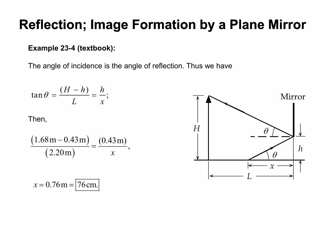
Example 23-4 (textbook): A person whose eyes are 1.68 m above the floor stands
2.20 m in front of a vertical plane mirror whose bottom edge is 43 cm above the
floor, Fig. 23–48. What is the horizontal distance x to the base of the wall
supporting the mirror of the nearest point on the floor that can be seen reflected in
the mirror?
Reflection; Image Formation by a Plane MirrorReflection; Image Formation by a Plane Mirror
Example 23-4 (textbook):
The angle of incidence is the angle of reflection. Thus we have
Then,
Mirror
H θ
( )tan ;
H h h
L xθ
−= =
H
h
x
L
θ
θ
( )( )
1.68m 0.43m (0.43m),
2.20m x
−=
0.76m 76cm.x = =

Formation of Images by Spherical MirrorsFormation of Images by Spherical Mirrors
Mirrors do not need to be flat. Actually, several mirrors are in fact curved (for
example, rearview mirrors on some cars are curved).
The most common type of curved mirror is the spherical.
A spherical mirror forms a section of a sphere.
There are two types of spherical mirrors:
Concave: The reflecting surface is on
the inner surface of the sphere.
Convex: The reflecting surface is on the
outer surface of the sphere.
Note: the law of reflection still applies for
curved mirrors.

Formation of Images by Spherical MirrorsFormation of Images by Spherical Mirrors
In order to study images formed by spherical mirrors, we will first consider objects
that are located very far from a concave mirror.
Rays coming from a faraway object are effectively parallel.
For example, it applies well to our sun and other stars located very distant from the
Earth.

Formation of Images by Spherical MirrorsFormation of Images by Spherical Mirrors
However, we consider the law of reflection, the rays coming from a point on a
distant object will not all converge at exactly the same place after reflecting on the
mirror. Unlike in flat mirrors, the image of the object formed by a spherical mirror
will be distorted.
This is what we call spherical aberration.This is what we call spherical aberration.

Formation of Images by Spherical MirrorsFormation of Images by Spherical Mirrors
Spherical aberrations can be significantly minimized if we use mirrors which are
smaller than its radius of curvature (r in the figure).
Or, equivalently, a mirror with a small curvature.
In this case, the angle between the incident and reflected rays are small (2θ in the
figure below) � the rays will then cross each other at very nearly a single point
called focus.
In the figure:In the figure:
C is the center of curvature of the mirror
F is the focal point (focus)
A is the center of the mirror
f = FA is called focal length
CA is called the principal axis.
The focal point is the image point of an
object located infinitely far away along the
principal axis.