Embed Size (px)
Citation preview
Chapter 26 Geometrical Optics26.1 The Reflection of Light
26.2 Forming Images With a Plane Mirror
26.3 Spherical Mirrors
26.4 Ray Tracing and the Mirror Equation
26.5 The Refraction of Light
26.6 Ray Tracing for Lenses
26.7 The Thin-Lens Equation
***The Reflection of Light: Mirrors: Mirrors produce images because the light that strikes them is reflected, rather than absorbed. Reflected light does much more than produce dramatic and beautiful pictures, however. For example, it allows our sense of vision to be remarkably useful. When we "see" an object, light from it enters our eyes and evokes the sensation of vision. Some objects themselves produce the light that we see, like the sun, a flame, or a light bulb. Most objects, though, reflect into our eyes light that originates elsewhere, and if it were not for reflection, we would not be able to see them. Much more practical applications of light reflection range from measuring the speeds of automobiles to reading price information from bar codes at the supermarket.
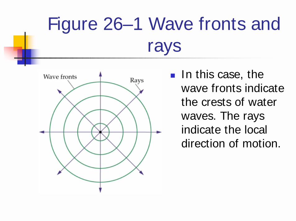
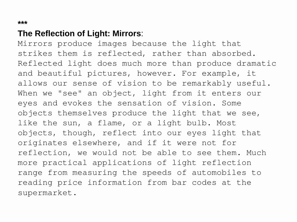
Figure 26–1 Wave fronts and rays
! In this case, the wave fronts indicate the crests of water waves. The rays indicate the local direction of motion.
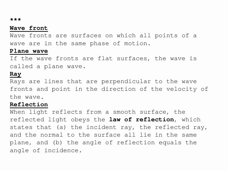
***Wave frontWave fronts are surfaces on which all points of a wave are in the same phase of motion.Plane waveIf the wave fronts are flat surfaces, the wave is called a plane wave.RayRays are lines that are perpendicular to the wave fronts and point in the direction of the velocity of the wave.ReflectionWhen light reflects from a smooth surface, the reflected light obeys the law of reflection, which states that (a) the incident ray, the reflected ray, and the normal to the surface all lie in the same plane, and (b) the angle of reflection equals the angle of incidence.
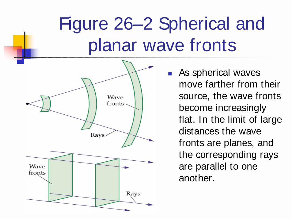
Figure 26–2 Spherical and planar wave fronts
! As spherical waves move farther from their source, the wave fronts become increasingly flat. In the limit of large distances the wave fronts are planes, and the corresponding rays are parallel to one another.

Figure 26–3 Reflection from a smooth surface
! In this simplified representation, the incident and reflected waves are indicated by single rays pointing in the direction of propagation. Notice that the angle of reflection, ηr, is equal to the angle of incidence, η i. In addition, the incident ray, reflected ray, and the normal all lie in the same plane.
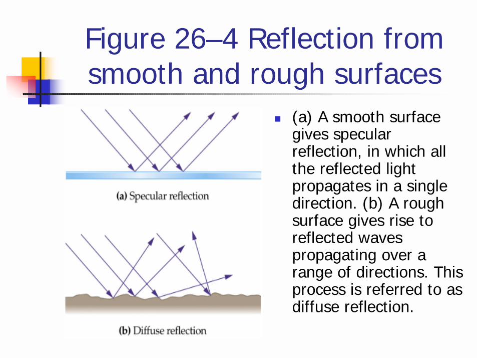
Figure 26–4 Reflection from smooth and rough surfaces
! (a) A smooth surface gives specularreflection, in which all the reflected light propagates in a single direction. (b) A rough surface gives rise to reflected waves propagating over a range of directions. This process is referred to as diffuse reflection.
***ImagesA virtual image is one from which rays of light do not actually come, but only appear to do so. A real image is one from which rays of light actually emanate.
Mirrors(a) A plane mirror forms an upright, virtual image that is located as far as the object is in front of it. In addition, the height of the image and the object are equal.(b) A spherical mirror has the shape of a section from the surface of a sphere.
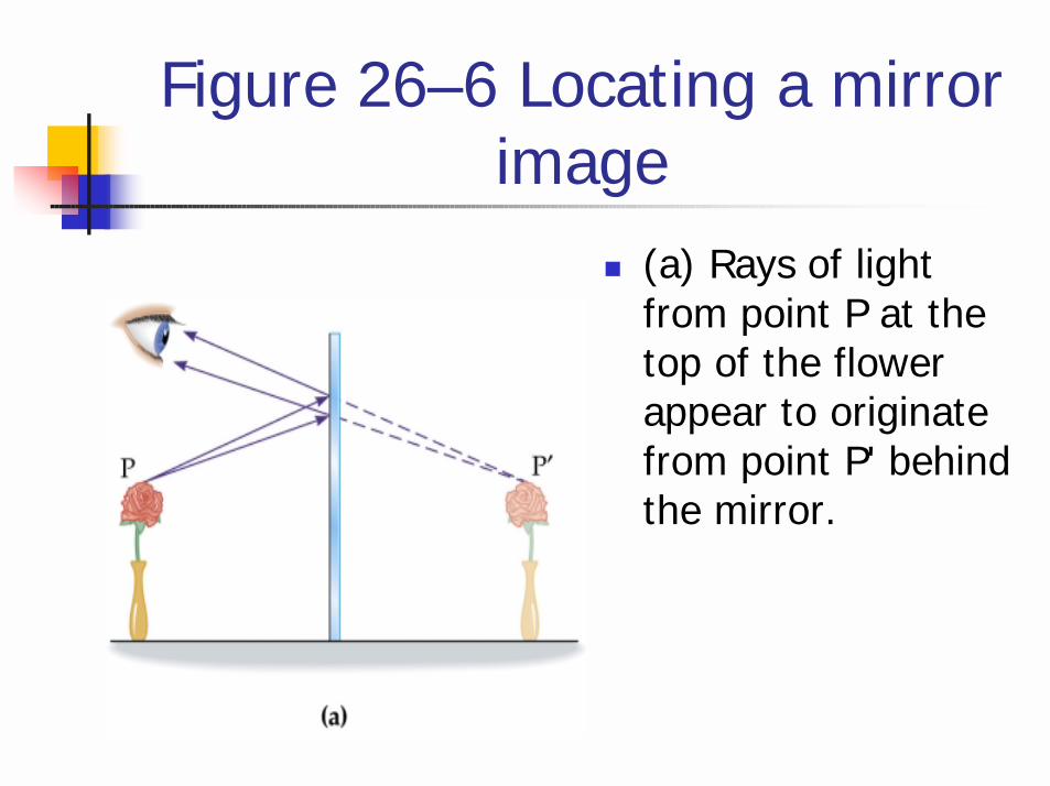
Figure 26–6 Locating a mirror image
! (a) Rays of light from point P at the top of the flower appear to originate from point P' behind the mirror.

Figure 26–6 Locating a mirror image
! (b) Construction showing that the distance from the object to the mirror is the same as the distance from the image to the mirror.
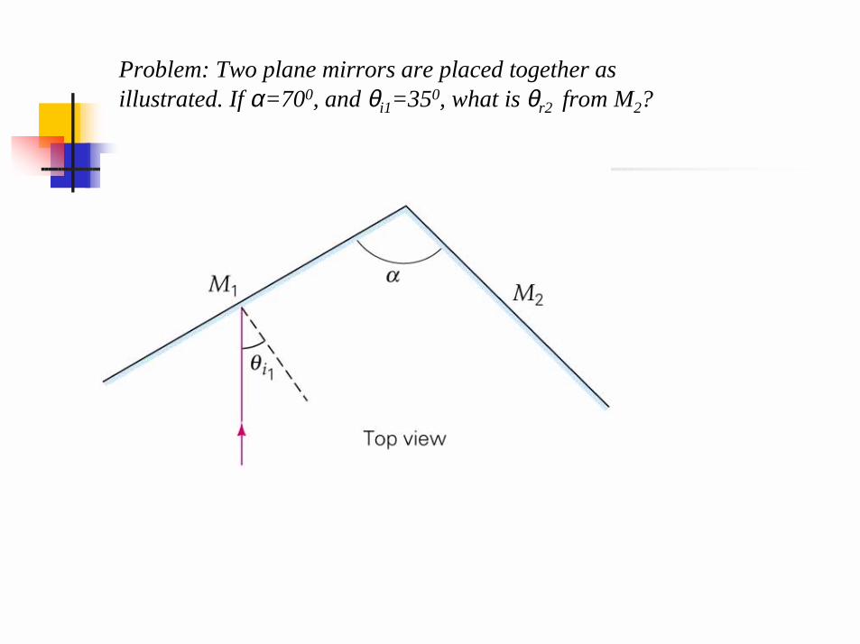
Problem: Two plane mirrors are placed together as illustrated. If α=700, and θi1=350, what is θr2 from M2?
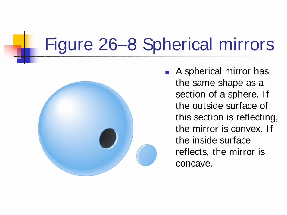
Figure 26–8 Spherical mirrors! A spherical mirror has
the same shape as a section of a sphere. If the outside surface of this section is reflecting, the mirror is convex. If the inside surface reflects, the mirror is concave.
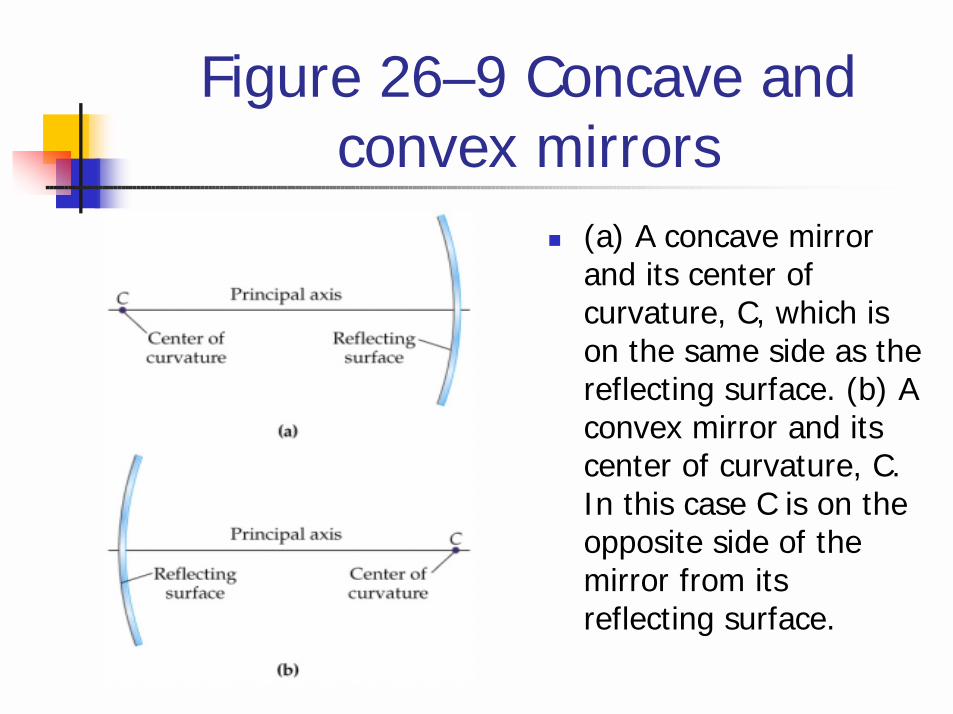
Figure 26–9 Concave and convex mirrors
! (a) A concave mirror and its center of curvature, C, which is on the same side as the reflecting surface. (b) A convex mirror and its center of curvature, C. In this case C is on the opposite side of the mirror from its reflecting surface.
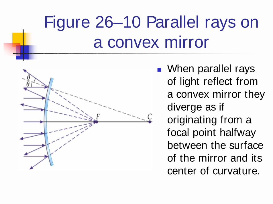
Figure 26–10 Parallel rays on a convex mirror
! When parallel rays of light reflect from a convex mirror they diverge as if originating from a focal point halfway between the surface of the mirror and its center of curvature.
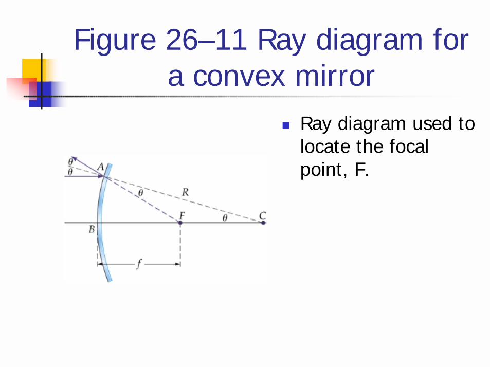
Figure 26–11 Ray diagram for a convex mirror
! Ray diagram used to locate the focal point, F.
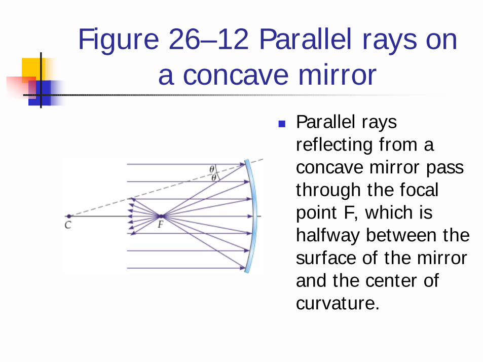
Figure 26–12 Parallel rays on a concave mirror
! Parallel rays reflecting from a concave mirror pass through the focal point F, which is halfway between the surface of the mirror and the center of curvature.

Figure 26–14 Principal rays used in ray tracing for a concave mirror
! The parallel ray (P ray) reflects through the focal point. The focal ray (F ray) reflects parallel to the axis, and the center-of-curvature ray (C ray) reflects back along its incoming path.
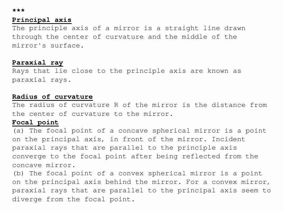
***Principal axisThe principle axis of a mirror is a straight line drawn through the center of curvature and the middle of the mirror's surface.
Paraxial rayRays that lie close to the principle axis are known as paraxial rays.
Radius of curvatureThe radius of curvature R of the mirror is the distance from the center of curvature to the mirror.Focal point(a) The focal point of a concave spherical mirror is a point on the principal axis, in front of the mirror. Incident paraxial rays that are parallel to the principle axis converge to the focal point after being reflected from the concave mirror.(b) The focal point of a convex spherical mirror is a point on the principal axis behind the mirror. For a convex mirror, paraxial rays that are parallel to the principal axis seem to diverge from the focal point.
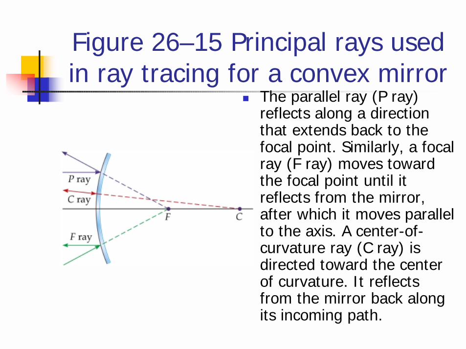
Figure 26–15 Principal rays used in ray tracing for a convex mirror
! The parallel ray (P ray) reflects along a direction that extends back to the focal point. Similarly, a focal ray (F ray) moves toward the focal point until it reflects from the mirror, after which it moves parallel to the axis. A center-of-curvature ray (C ray) is directed toward the center of curvature. It reflects from the mirror back along its incoming path.
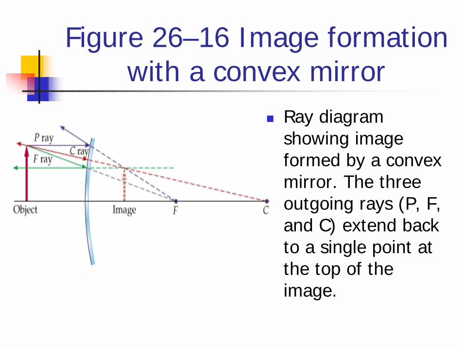
Figure 26–16 Image formation with a convex mirror
! Ray diagram showing image formed by a convex mirror. The three outgoing rays (P, F, and C) extend back to a single point at the top of the image.

Figure 26–17 Image size and location in a convex mirror
! (a) When an object is close to a convex mirror the image is practically the same size and distance from the mirror. (b) In the limit that the object is very far from the mirror the image is small and close to the focal point.
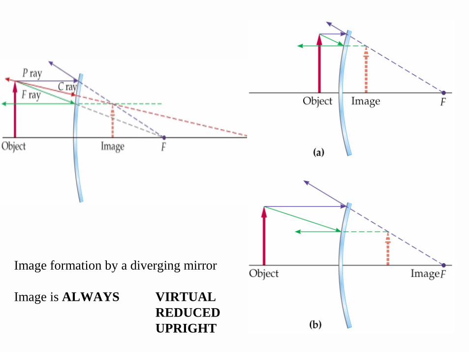
Image formation by a diverging mirror
Image is ALWAYS VIRTUALREDUCED UPRIGHT
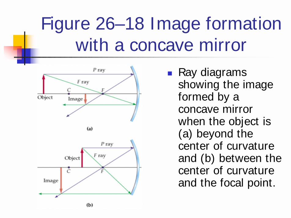
Figure 26–18 Image formation with a concave mirror
! Ray diagrams showing the image formed by a concave mirror when the object is (a) beyond the center of curvature and (b) between the center of curvature and the focal point.
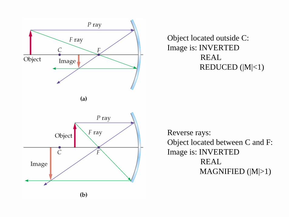
Object located outside C:Image is: INVERTED
REALREDUCED (|M|<1)
Reverse rays:Object located between C and F:Image is: INVERTED
REALMAGNIFIED (|M|>1)
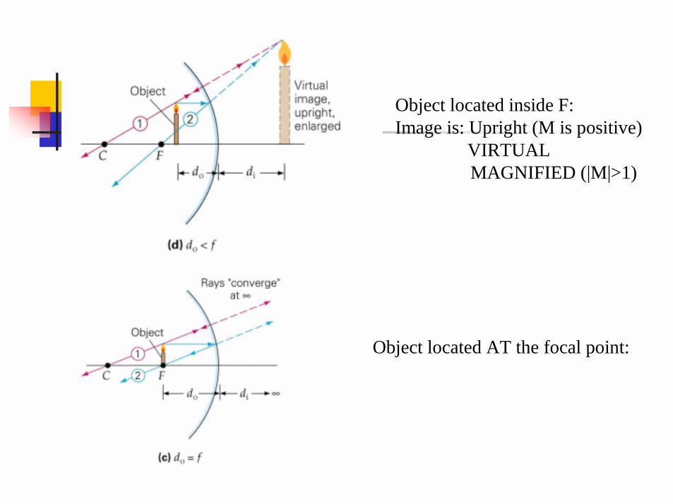
Object located inside F:Image is: Upright (M is positive)
VIRTUALMAGNIFIED (|M|>1)
Object located AT the focal point:
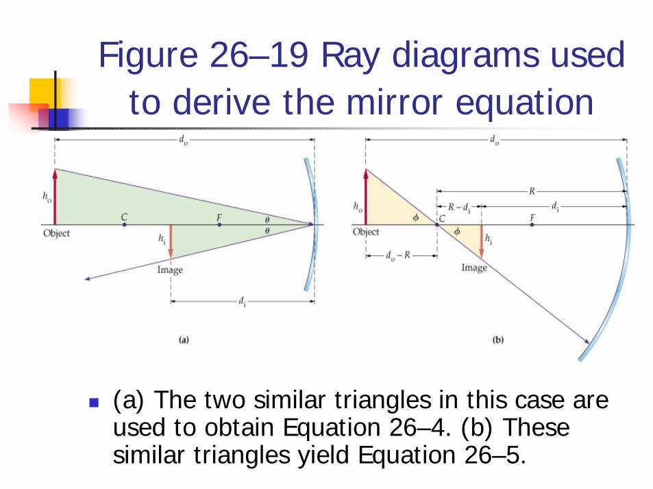
Figure 26–19 Ray diagrams used to derive the mirror equation
! (a) The two similar triangles in this case are used to obtain Equation 26–4. (b) These similar triangles yield Equation 26–5.
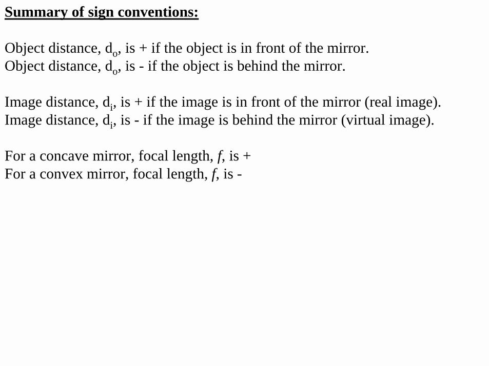
Summary of sign conventions:
Object distance, do, is + if the object is in front of the mirror.Object distance, do, is - if the object is behind the mirror.
Image distance, di, is + if the image is in front of the mirror (real image).Image distance, di, is - if the image is behind the mirror (virtual image).
For a concave mirror, focal length, f, is +For a convex mirror, focal length, f, is -
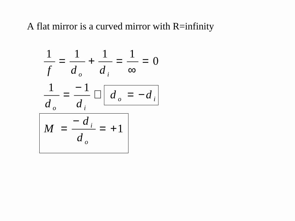
A flat mirror is a curved mirror with R=infinity
1
11
01111
+=−
=
−=⇒−=
=∞
=+=
o
i
ioio
io
ddM
dddd
ddf
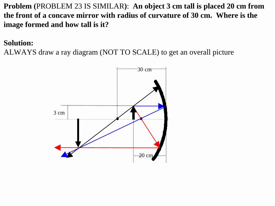
Problem (PROBLEM 23 IS SIMILAR): An object 3 cm tall is placed 20 cm from the front of a concave mirror with radius of curvature of 30 cm. Where is the image formed and how tall is it?
Solution:ALWAYS draw a ray diagram (NOT TO SCALE) to get an overall picture
30 cm
20 cm
3 cm

From ray diagram, Image is REAL, INVERTED and MAGNIFIED
di is positive, M is negative, and |M|>1
Any calculations have to agree with these observations.
di = fd0 / (d0-f) = (+15)(+20) / (20 – 15) = +60 cm
THIS CALCULATION AGREES WITH THE RAY DIAGRAM
M = -di / d0 = -(+60) / (+20) = -3
THIS CALCULATION ALSO AGREES WITH THE RAY DIAGRAM.
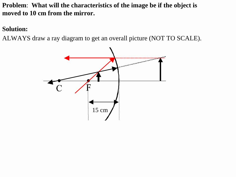
Problem: What will the characteristics of the image be if the object is moved to 10 cm from the mirror.
Solution:ALWAYS draw a ray diagram to get an overall picture (NOT TO SCALE).
15 cm
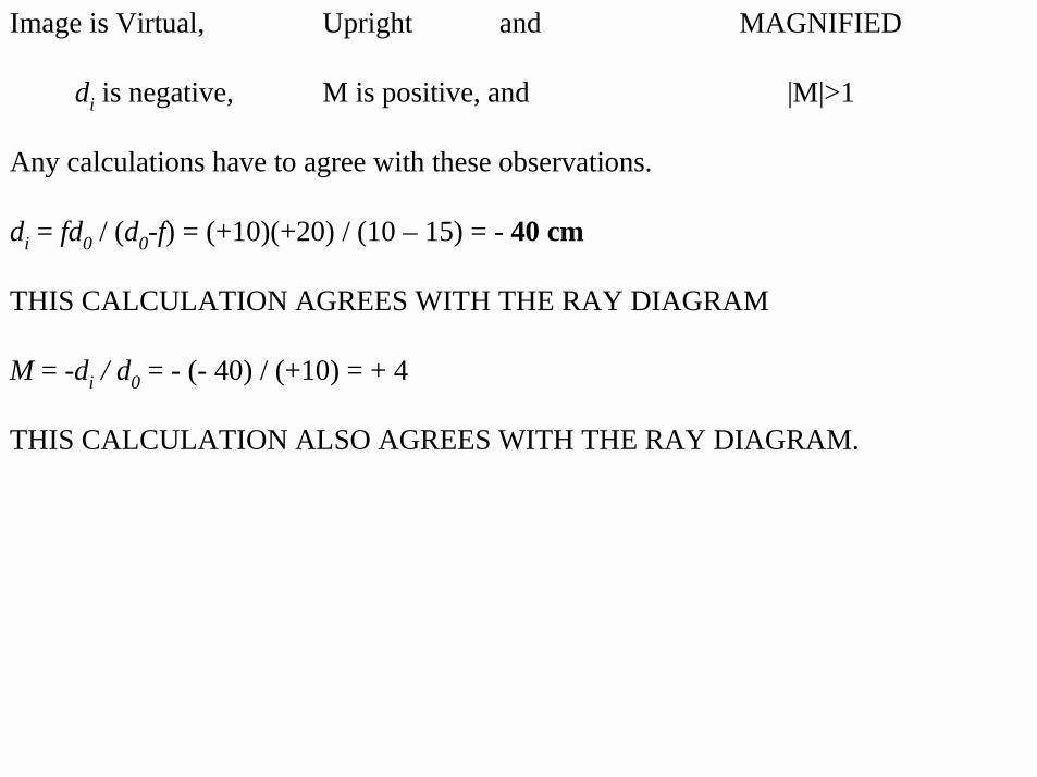
Image is Virtual, Upright and MAGNIFIED
di is negative, M is positive, and |M|>1
Any calculations have to agree with these observations.
di = fd0 / (d0-f) = (+10)(+20) / (10 – 15) = - 40 cm
THIS CALCULATION AGREES WITH THE RAY DIAGRAM
M = -di / d0 = - (- 40) / (+10) = + 4
THIS CALCULATION ALSO AGREES WITH THE RAY DIAGRAM.
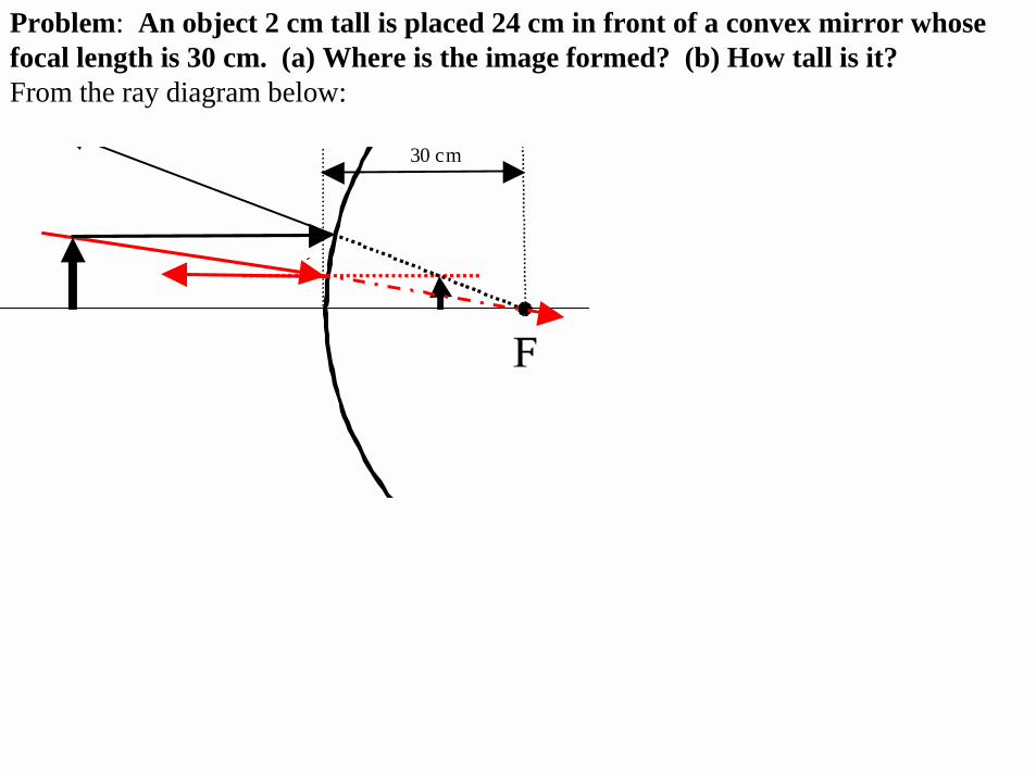
Problem: An object 2 cm tall is placed 24 cm in front of a convex mirror whose focal length is 30 cm. (a) Where is the image formed? (b) How tall is it?From the ray diagram below:
30 cm
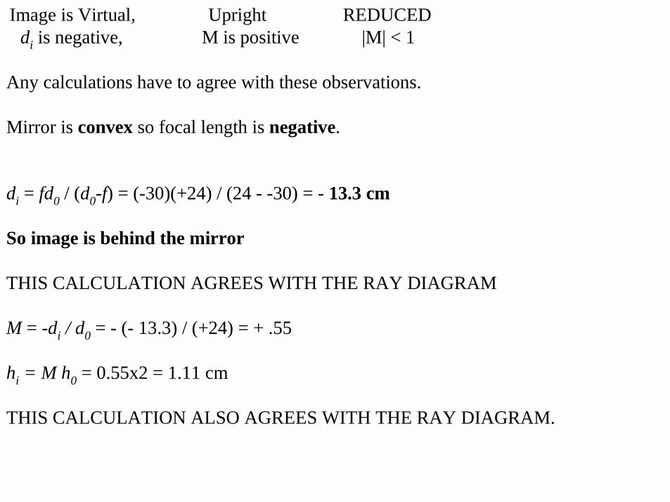
di = fd0 / (d0-f) = (-30)(+24) / (24 - -30) = - 13.3 cm
So image is behind the mirror
THIS CALCULATION AGREES WITH THE RAY DIAGRAM
M = -di / d0 = - (- 13.3) / (+24) = + .55
hi = M h0 = 0.55x2 = 1.11 cm
THIS CALCULATION ALSO AGREES WITH THE RAY DIAGRAM.
Image is Virtual, Upright REDUCEDdi is negative, M is positive |M| < 1
Any calculations have to agree with these observations.
Mirror is convex so focal length is negative.
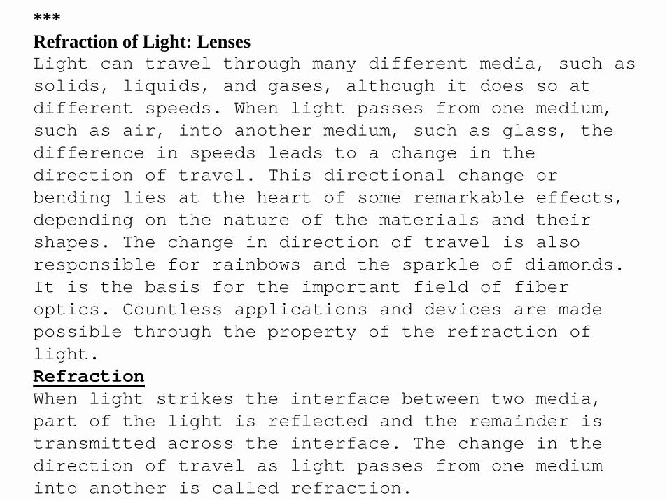
***Refraction of Light: Lenses Light can travel through many different media, such as solids, liquids, and gases, although it does so at different speeds. When light passes from one medium, such as air, into another medium, such as glass, the difference in speeds leads to a change in the direction of travel. This directional change or bending lies at the heart of some remarkable effects, depending on the nature of the materials and their shapes. The change in direction of travel is also responsible for rainbows and the sparkle of diamonds. It is the basis for the important field of fiber optics. Countless applications and devices are made possible through the property of the refraction of light. RefractionWhen light strikes the interface between two media, part of the light is reflected and the remainder is transmitted across the interface. The change in the direction of travel as light passes from one medium into another is called refraction.
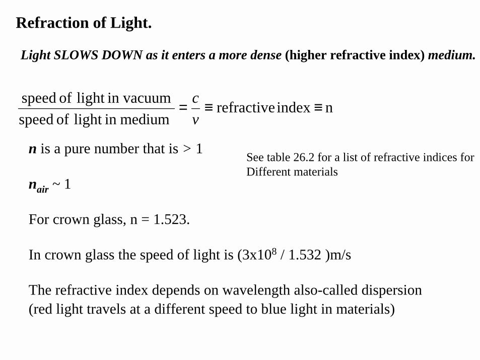
Refraction of Light.
Light SLOWS DOWN as it enters a more dense (higher refractive index) medium.
n index refractive mediumin light of speed
in vacuumlight of speed ≡≡=vc
n is a pure number that is > 1
nair ~ 1
For crown glass, n = 1.523.
In crown glass the speed of light is (3x10⁸ / 1.532 )m/s
The refractive index depends on wavelength also-called dispersion(red light travels at a different speed to blue light in materials)
See table 26.2 for a list of refractive indices for Different materials
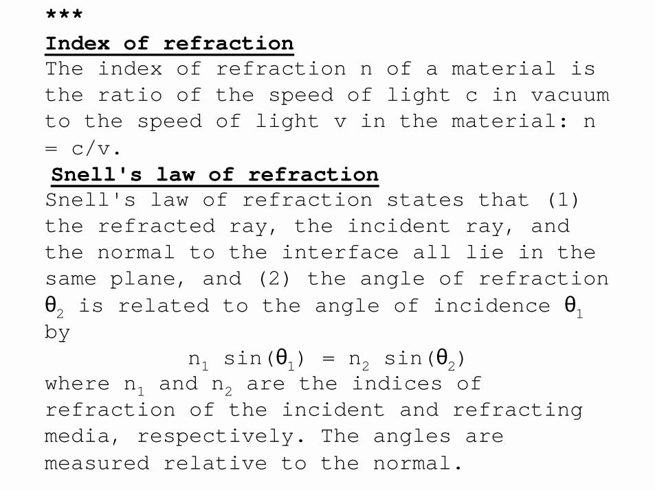
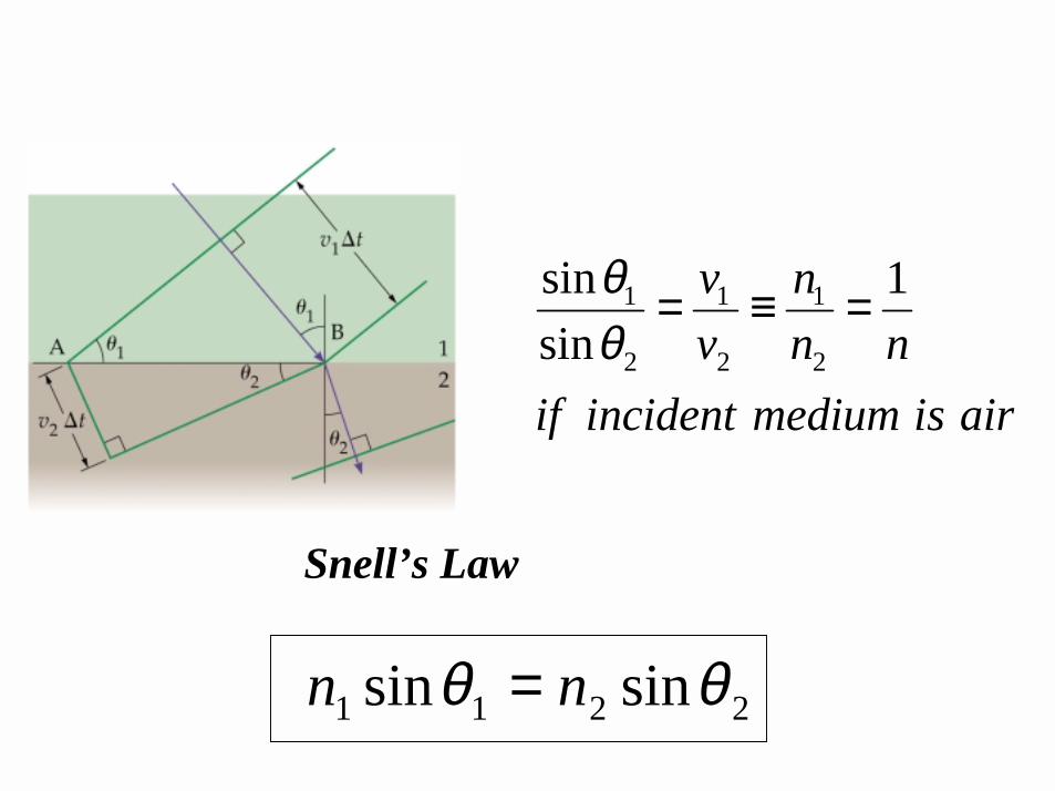
***Index of refractionThe index of refraction n of a material is the ratio of the speed of light c in vacuum to the speed of light v in the material: n = c/v.Snell's law of refractionSnell's law of refraction states that (1) the refracted ray, the incident ray, and the normal to the interface all lie in the same plane, and (2) the angle of refraction θ2 is related to the angle of incidence θ1by
n1 sin(θ1) = n2 sin(θ2)where n1 and n2 are the indices of refraction of the incident and refracting media, respectively. The angles are measured relative to the normal.
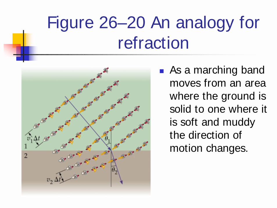
Figure 26–20 An analogy for refraction
! As a marching band moves from an area where the ground is solid to one where it is soft and muddy the direction of motion changes.
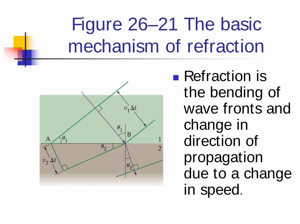
Figure 26–21 The basic mechanism of refraction
! Refraction is the bending of wave fronts and change in direction of propagation due to a change in speed.
1 1 1
2 2 2
sin 1sin
v nv n n
if incident medium is air
θθ
= ≡ =
2211 sinsin θθ nn =
Snell’s Law
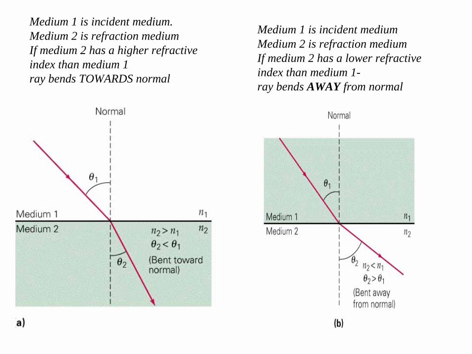
Medium 1 is incident medium. Medium 2 is refraction mediumIf medium 2 has a higher refractive index than medium 1ray bends TOWARDS normal
Medium 1 is incident mediumMedium 2 is refraction mediumIf medium 2 has a lower refractive index than medium 1-ray bends AWAY from normal

Apparent depth. Ray appears like it is coming from here.
What is x?
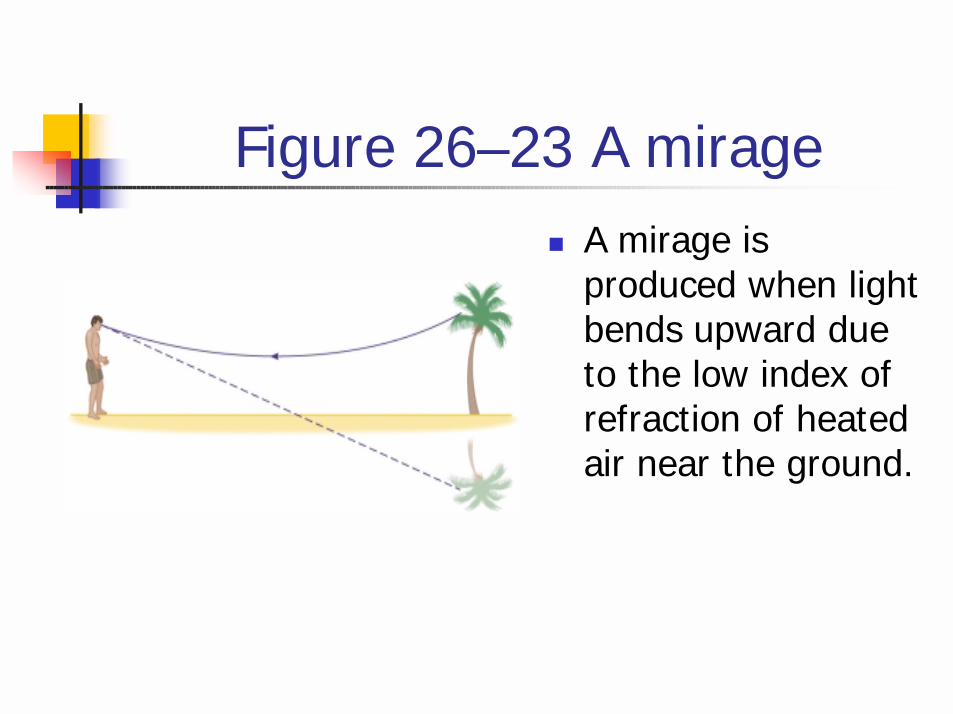
Figure 26–23 A mirage! A mirage is
produced when light bends upward due to the low index of refraction of heated air near the ground.
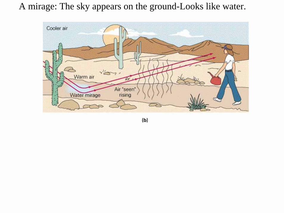
A mirage: The sky appears on the ground-Looks like water.
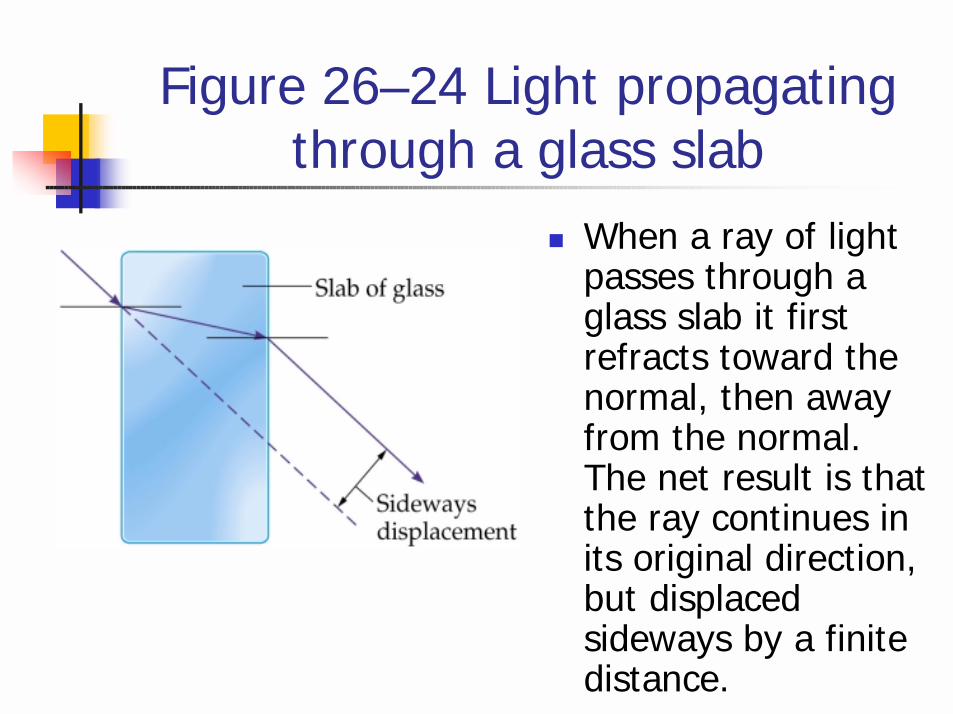
Figure 26–24 Light propagating through a glass slab
! When a ray of light passes through a glass slab it first refracts toward the normal, then away from the normal. The net result is that the ray continues in its original direction, but displaced sideways by a finite distance.
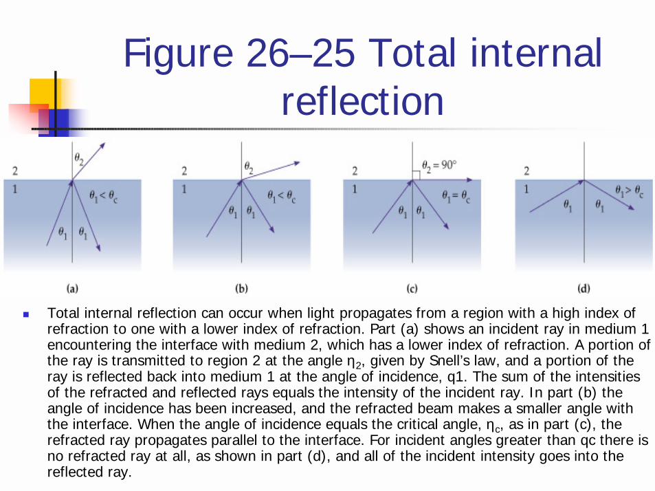
Figure 26–25 Total internal reflection
! Total internal reflection can occur when light propagates from a region with a high index of refraction to one with a lower index of refraction. Part (a) shows an incident ray in medium 1 encountering the interface with medium 2, which has a lower index of refraction. A portion of the ray is transmitted to region 2 at the angle η2, given by Snell’s law, and a portion of the ray is reflected back into medium 1 at the angle of incidence, q1. The sum of the intensities of the refracted and reflected rays equals the intensity of the incident ray. In part (b) the angle of incidence has been increased, and the refracted beam makes a smaller angle with the interface. When the angle of incidence equals the critical angle, ηc, as in part (c), the refracted ray propagates parallel to the interface. For incident angles greater than qc there is no refracted ray at all, as shown in part (d), and all of the incident intensity goes into the reflected ray.
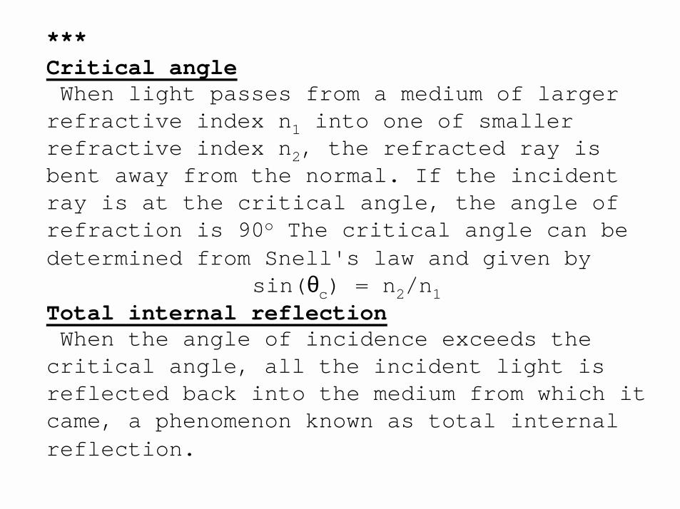
***Critical angleWhen light passes from a medium of larger
refractive index n1 into one of smaller refractive index n2, the refracted ray is bent away from the normal. If the incident ray is at the critical angle, the angle of refraction is 90o The critical angle can be determined from Snell's law and given by
sin(θc) = n2/n1Total internal reflectionWhen the angle of incidence exceeds the
critical angle, all the incident light is reflected back into the medium from which it came, a phenomenon known as total internal reflection.
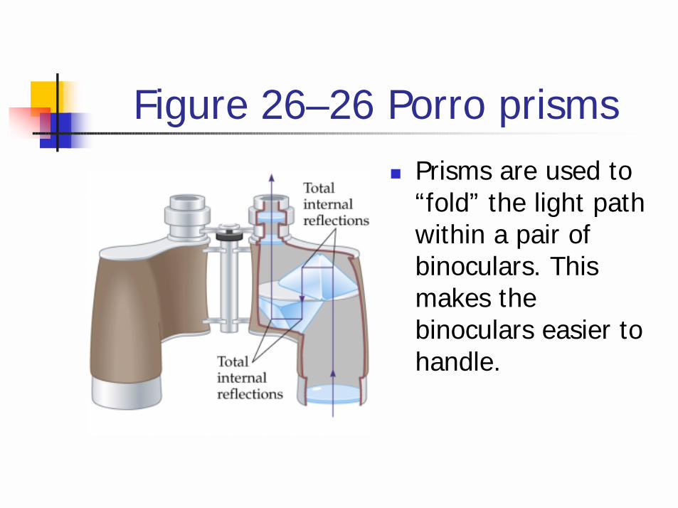
Figure 26–26 Porro prisms! Prisms are used to
“fold” the light path within a pair of binoculars. This makes the binoculars easier to handle.
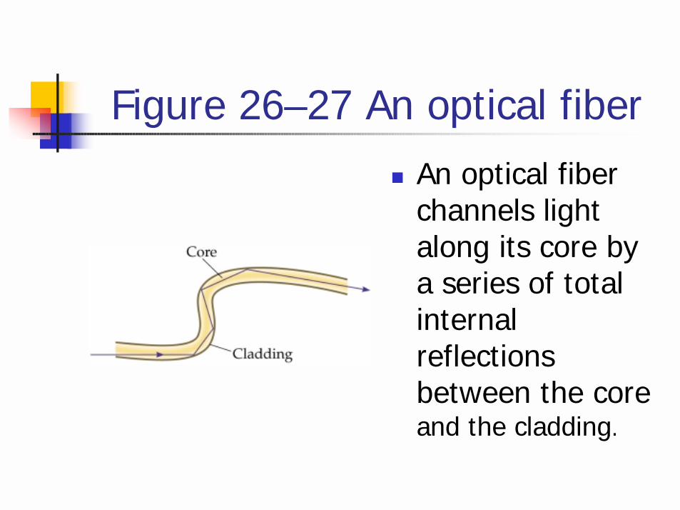
Figure 26–27 An optical fiber
! An optical fiber channels light along its core by a series of total internal reflections between the coreand the cladding.
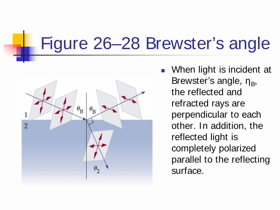
Figure 26–28 Brewster’s angle! When light is incident at
Brewster’s angle, ηB, the reflected and refracted rays are perpendicular to each other. In addition, the reflected light is completely polarized parallel to the reflecting surface.
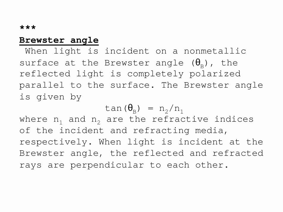
***Brewster angleWhen light is incident on a nonmetallic
surface at the Brewster angle (θB), the reflected light is completely polarized parallel to the surface. The Brewster angle is given by
tan(θB) = n2/n1where n1 and n2 are the refractive indices of the incident and refracting media, respectively. When light is incident at the Brewster angle, the reflected and refracted rays are perpendicular to each other.
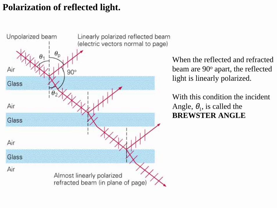
Polarization of reflected light.
When the reflected and refracted beam are 90o apart, the reflected light is linearly polarized.
With this condition the incident Angle, θ1, is called the BREWSTER ANGLE
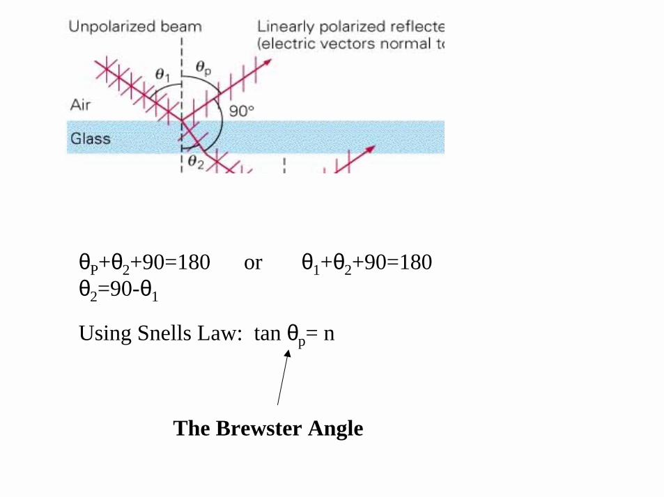
θP+θ2+90=180 or θ1+θ2+90=180 θ2=90-θ1
Using Snells Law: tan θp= n
The Brewster Angle
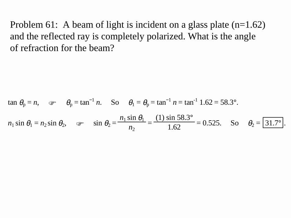
Problem 61: A beam of light is incident on a glass plate (n=1.62)and the reflected ray is completely polarized. What is the angleof refraction for the beam?
tan θp = n, " θp = tan−1 n. So θ1 = θp = tan−1 n = tan-1 1.62 = 58.3°.
n1 sin θ1 = n2 sin θ2, " sin θ2 = n1 sin θ1
n2 =
(1) sin 58.3° 1.62 = 0.525. So θ2 = 31.7° .
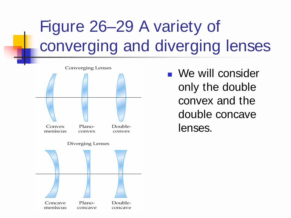
Figure 26–29 A variety of converging and diverging lenses
! We will consider only the double convex and the double concave lenses.

Lens ***The lenses used in optical instruments,
such as eyeglasses, cameras, and telescopes, are made from transparent materials they refract light. They refract the light in such a way that an image of the source of the light is formed. Depending on the phenomenon of refraction in forming an image, lenses are classified into two types: converging lenses and diverging lenses. (a) With a converging lens, paraxial rays that are parallel to the principal axis are focuses to a point on the axis by the lens (see Figure 26.30). (b) With a diverging lens, paraxial rays that are parallel to the principal axis appear to originate from its focal point after passing through the lens (see Figure 26-31).
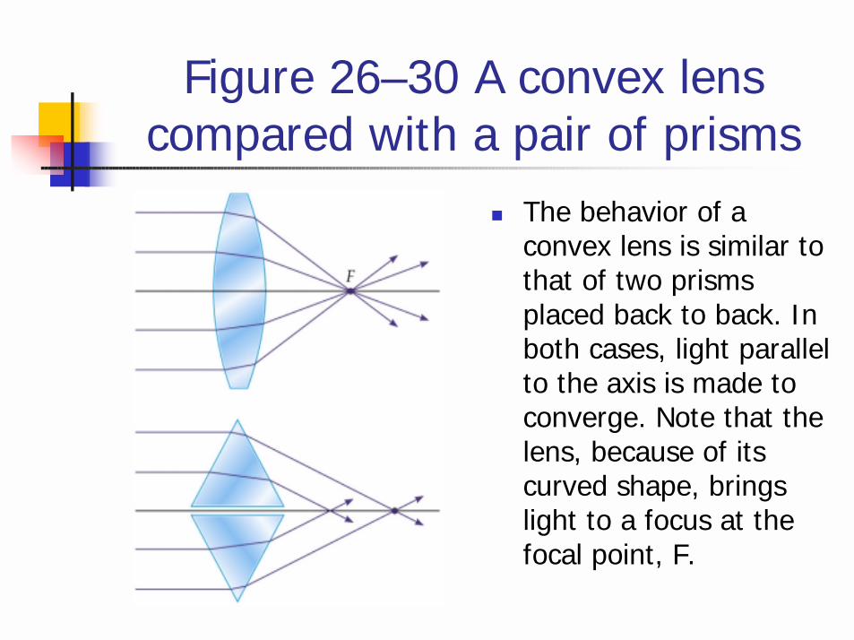
Figure 26–30 A convex lens compared with a pair of prisms
! The behavior of a convex lens is similar to that of two prisms placed back to back. In both cases, light parallel to the axis is made to converge. Note that the lens, because of its curved shape, brings light to a focus at the focal point, F.
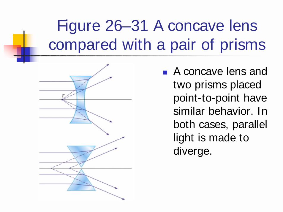
Figure 26–31 A concave lens compared with a pair of prisms
! A concave lens and two prisms placed point-to-point have similar behavior. In both cases, parallel light is made to diverge.
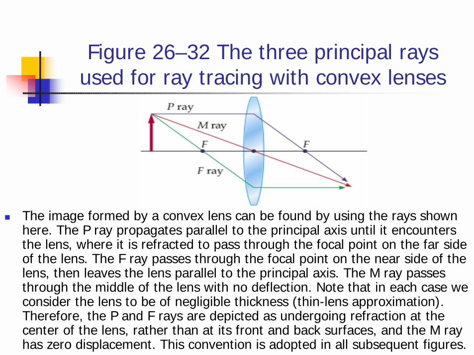
Figure 26–32 The three principal rays used for ray tracing with convex lenses
! The image formed by a convex lens can be found by using the rays shown here. The P ray propagates parallel to the principal axis until it encounters the lens, where it is refracted to pass through the focal point on the far side of the lens. The F ray passes through the focal point on the near side of the lens, then leaves the lens parallel to the principal axis. The M ray passes through the middle of the lens with no deflection. Note that in each case we consider the lens to be of negligible thickness (thin-lens approximation). Therefore, the P and F rays are depicted as undergoing refraction at the center of the lens, rather than at its front and back surfaces, and the M ray has zero displacement. This convention is adopted in all subsequent figures.

***Focal point(a) The focal point of a converging lens is a point on the principal axis. Incident paraxial rays that are parallel to the principle axis converge to the focal point after passing through the lens.(b) The focal point of a diverging lens is a point on the principal axis. Incident paraxial rays that are parallel to the principal axis seem to originate from the focal point after passing through the lens. Focal lengthThe distance from the focal point to the lens along its principal axis.
Ray diagramThe image produced by a converging or a diverging lens can be located using a technique called ray diagram. See Figure 26-33,26-34,26-35 for the detailed constructing steps.
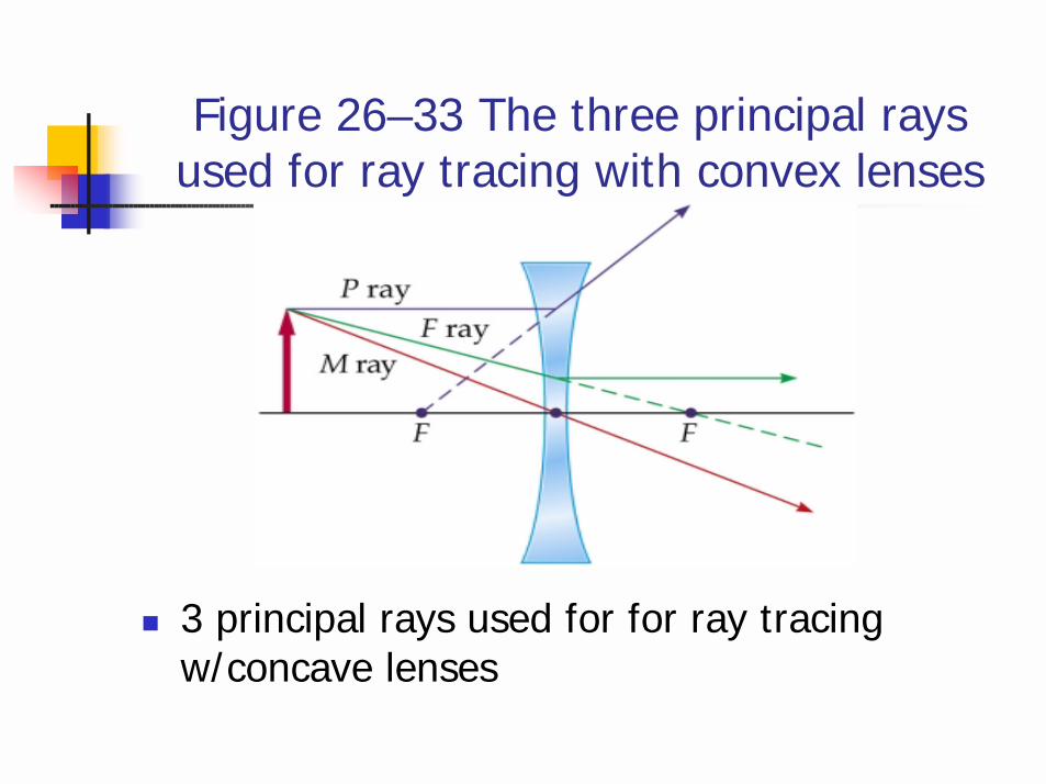
Figure 26–33 The three principal rays used for ray tracing with convex lenses
! 3 principal rays used for for ray tracing w/concave lenses
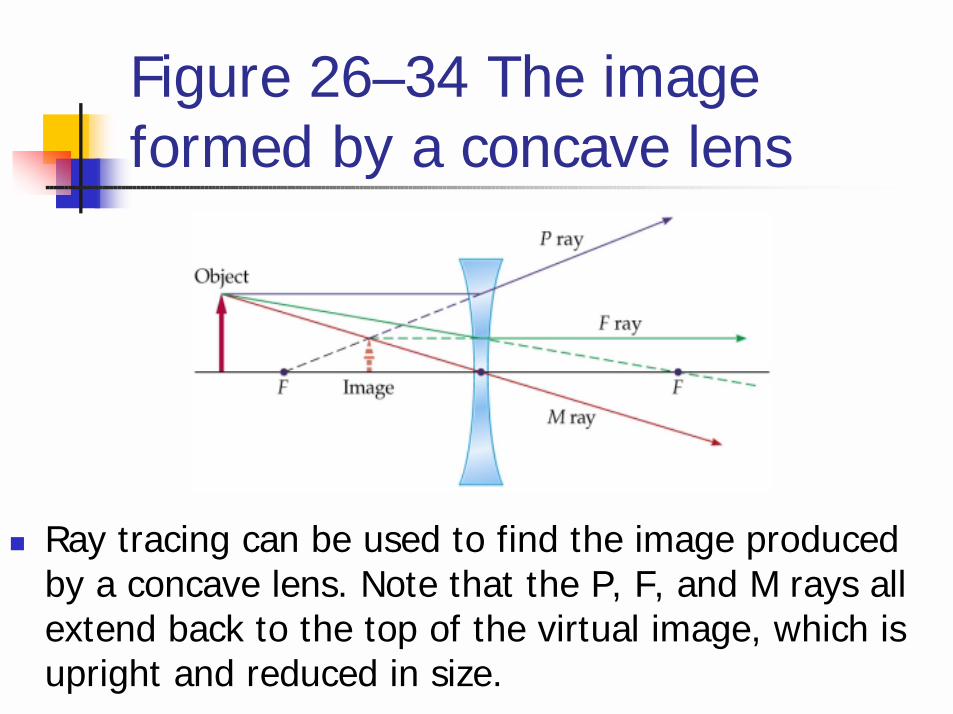
Figure 26–34 The image formed by a concave lens
! Ray tracing can be used to find the image produced by a concave lens. Note that the P, F, and M rays all extend back to the top of the virtual image, which is upright and reduced in size.
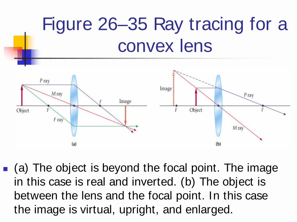
Figure 26–35 Ray tracing for a convex lens
! (a) The object is beyond the focal point. The image in this case is real and inverted. (b) The object is between the lens and the focal point. In this case the image is virtual, upright, and enlarged.
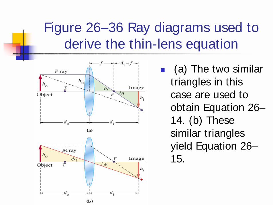
Figure 26–36 Ray diagrams used to derive the thin-lens equation
! (a) The two similar triangles in this case are used to obtain Equation 26–14. (b) These similar triangles yield Equation 26–15.
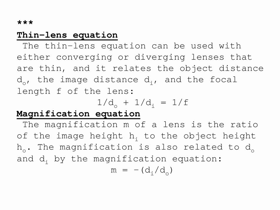
***Thin-lens equationThe thin-lens equation can be used with
either converging or diverging lenses that are thin, and it relates the object distance do, the image distance di, and the focal length f of the lens:
1/do + 1/di = 1/fMagnification equationThe magnification m of a lens is the ratio
of the image height hi to the object height ho. The magnification is also related to doand di by the magnification equation:
m = -(di/do)
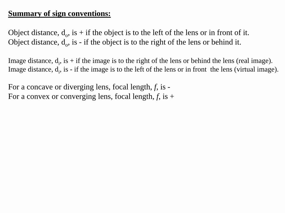
Summary of sign conventions:
Object distance, do, is + if the object is to the left of the lens or in front of it.Object distance, do, is - if the object is to the right of the lens or behind it.
Image distance, di, is + if the image is to the right of the lens or behind the lens (real image).Image distance, di, is - if the image is to the left of the lens or in front the lens (virtual image).
For a concave or diverging lens, focal length, f, is -For a convex or converging lens, focal length, f, is +
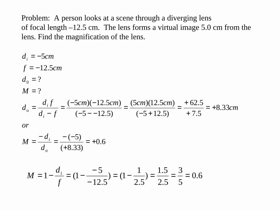
Problem: A person looks at a scene through a diverging lensof focal length –12.5 cm. The lens forms a virtual image 5.0 cm from the lens. Find the magnification of the lens.
6.0)33.8()5(
33.85.75.62
)5.125()5.12)(5(
)5.125()5.12)(5(
??
5.125
0
+=+
−−=−
=
+=++=
+−=
−−−−−=
−=
==−=−=
o
i
i
io
i
ddM
or
cmcmcmcmcmfd
fdd
Md
cmfcmd
6.053
5.25.1)
5.211()
5.1251(1 ===−=
−−−=−=
fdM i