Embed Size (px)
Citation preview
27.1
Chapter 27: Current & Resistance
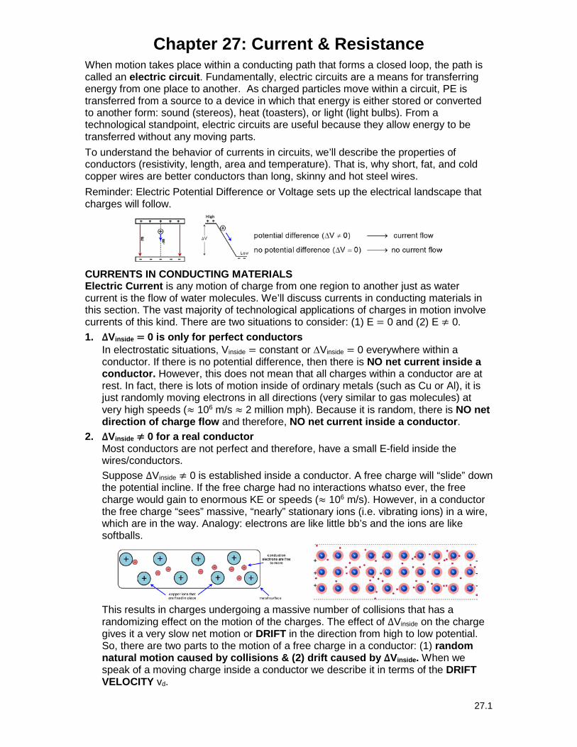
When motion takes place within a conducting path that forms a closed loop, the path is called an electric circuit. Fundamentally, electric circuits are a means for transferring energy from one place to another. As charged particles move within a circuit, PE is transferred from a source to a device in which that energy is either stored or converted to another form: sound (stereos), heat (toasters), or light (light bulbs). From a technological standpoint, electric circuits are useful because they allow energy to be transferred without any moving parts. To understand the behavior of currents in circuits, we’ll describe the properties of conductors (resistivity, length, area and temperature). That is, why short, fat, and cold copper wires are better conductors than long, skinny and hot steel wires. Reminder: Electric Potential Difference or Voltage sets up the electrical landscape that charges will follow.
CURRENTS IN CONDUCTING MATERIALS Electric Current is any motion of charge from one region to another just as water current is the flow of water molecules. We’ll discuss currents in conducting materials in this section. The vast majority of technological applications of charges in motion involve currents of this kind. There are two situations to consider: (1) E = 0 and (2) E ≠ 0. 1. ∆Vinside = 0 is only for perfect conductors
In electrostatic situations, Vinside = constant or ∆Vinside = 0 everywhere within a conductor. If there is no potential difference, then there is NO net current inside a conductor. However, this does not mean that all charges within a conductor are at rest. In fact, there is lots of motion inside of ordinary metals (such as Cu or Al), it is just randomly moving electrons in all directions (very similar to gas molecules) at very high speeds (≈ 106 m/s ≈ 2 million mph). Because it is random, there is NO net direction of charge flow and therefore, NO net current inside a conductor.
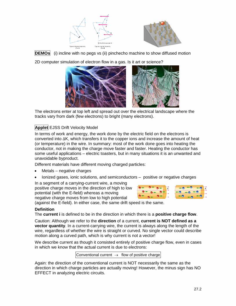
2. ∆Vinside ≠ 0 for a real conductor Most conductors are not perfect and therefore, have a small E-field inside the wires/conductors. Suppose ∆Vinside ≠ 0 is established inside a conductor. A free charge will “slide” down the potential incline. If the free charge had no interactions whatso ever, the free charge would gain to enormous KE or speeds (≈ 106 m/s). However, in a conductor the free charge “sees” massive, “nearly” stationary ions (i.e. vibrating ions) in a wire, which are in the way. Analogy: electrons are like little bb’s and the ions are like softballs.
This results in charges undergoing a massive number of collisions that has a randomizing effect on the motion of the charges. The effect of ∆Vinside on the charge gives it a very slow net motion or DRIFT in the direction from high to low potential. So, there are two parts to the motion of a free charge in a conductor: (1) random natural motion caused by collisions & (2) drift caused by ∆Vinside. When we speak of a moving charge inside a conductor we describe it in terms of the DRIFT VELOCITY vd.
27.2
DEMOs (i) incline with no pegs vs (ii) pinchecho machine to show diffused motion
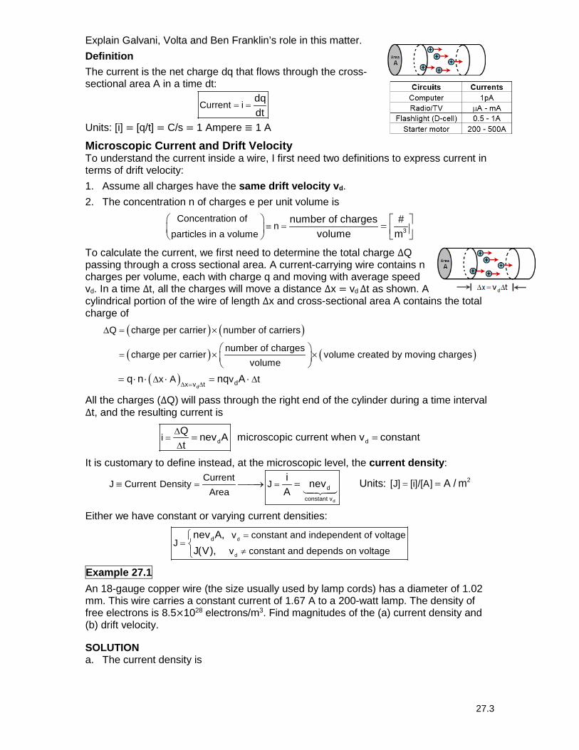
2D computer simulation of electron flow in a gas. Is it art or science?
The electrons enter at top left and spread out over the electrical landscape where the tracks vary from dark (few electrons) to bright (many electrons).
Applet EJSS Drift Velocity Model In terms of work and energy, the work done by the electric field on the electrons is converted into ∆K, which transfers it to the copper ions and increase the amount of heat (or temperature) in the wire. In summary: most of the work done goes into heating the conductor, not in making the charge move faster and faster. Heating the conductor has some useful applications – electric toasters, but in many situations it is an unwanted and unavoidable byproduct. Different materials have different moving charged particles: • Metals – negative charges • Ionized gases, ionic solutions, and semiconductors – positive or negative charges In a segment of a carrying-current wire, a moving positive charge moves in the direction of high to low potential (with the E-field) whereas a moving negative charge moves from low to high potential (against the E-field). In either case, the same drift speed is the same.
Definition The current i is defined to be in the direction in which there is a positive charge flow.
Caution: Although we refer to the direction of a current, current is NOT defined as a vector quantity. In a current-carrying wire, the current is always along the length of the wire, regardless of whether the wire is straight or curved. No single vector could describe motion along a curved path, which is why current is not a vector!
We describe current as though it consisted entirely of positive charge flow, even in cases in which we know that the actual current is due to electrons:
Conventional current flow of positive charge→
Again: the direction of the conventional current is NOT necessarily the same as the direction in which charge particles are actually moving! However, the minus sign has NO EFFECT in analyzing electric circuits.
27.3
Explain Galvani, Volta and Ben Franklin’s role in this matter. Definition The current is the net charge dq that flows through the cross-sectional area A in a time dt:
Current idqdt
= =
Units: [i] = [q/t] = C/s = 1 Ampere ≡ 1 A
Microscopic Current and Drift Velocity To understand the current inside a wire, I first need two definitions to express current in terms of drift velocity: 1. Assume all charges have the same drift velocity vd. 2. The concentration n of charges e per unit volume is
3
Concentration of n
particles in a volumenumber of charges #
volume m≡ =
=
To calculate the current, we first need to determine the total charge ∆Q passing through a cross sectional area. A current-carrying wire contains n charges per volume, each with charge q and moving with average speed vd. In a time ∆t, all the charges will move a distance ∆x = vd ∆t as shown. A cylindrical portion of the wire of length ∆x and cross-sectional area A contains the total charge of
( ) ( )
( ) ( )
( )d
dx v t
Q charge per carrier number of carriers
number of charges charge per carrier volume created by moving charges
volume
x A v t q n nq A∆ = ∆
∆ =
=
∆ ∆
×
× ×
= ⋅ ⋅ ⋅ = ⋅
All the charges (∆Q) will pass through the right end of the cylinder during a time interval ∆t, and the resulting current is
d diQ nev A microscopic current when v constantt
∆=
∆= =
It is customary to define instead, at the microscopic level, the current density:
d
d
constant v
CurrentJ Current Density J
Areai nev A
= =≡ → =
Units: 2[J] [i]/[A] A / m= =
Either we have constant or varying current densities:
d
d
d v constant and independent of voltageJ
v constant and depends on voltage
nev A, J(V),
==
≠
Example 27.1 An 18-gauge copper wire (the size usually used by lamp cords) has a diameter of 1.02 mm. This wire carries a constant current of 1.67 A to a 200-watt lamp. The density of free electrons is 8.5×1028 electrons/m3. Find magnitudes of the (a) current density and (b) drift velocity.
SOLUTION a. The current density is
27.4
π π214
6 33 21
4A d
1.67AJ 2.04 10 A/m J
1.02 10i A ( )−
=
= = = ××
=
b. Using the current density to solve for the drift velocity,
d
6 3solving 4
d d dfor v 28 3 19J 2.04 10 A/m
J 1.5 10 m/s 0.15 mm/s vne 8.5 10 m 1.6 10 C
nev v( )( )
−− −
×= = × = =
× ×→ = =
At this speed an electron would require 1 hr, 50 min to travel the length of a wire 1 m long. The speed of random motion (106 m/s) is 1010 times faster. Picture wise, the electrons are bouncing around frantically, with a very slow and sluggish drift! If the electrons move this slowly, you may wonder why the light comes on right away when you turn on the switch. Let use an analogy to explain it. Interpretation: consider what happens when a jump start is given to a bad battery. If the jumper cables are 2m-long, the charges coming out of one car would take 3 hrs, 40 min to reach the other car. If you are of the understanding that charges flow out of the good battery and charge up the bad battery, then your wait should be a considerable to await the arrive of the electrons. Picture wise, when the jump cables are attached to the car with the bad battery, the bad battery and most importantly, the car’s starter is on the potential incline. As soon as the cables are attached, ALL of the charges will move simultaneously and the charges already in the starter will “slide” from high to low potential. Once the car’s engine starts, then the bad car’s alternator begins the process of charging the bad battery. Other examples that are similar are (i) electric shock and (ii) light bulbs Interesting point Charges in a conductor have very high average random velocities (2 million mph). One would think that the electrons would leave the surface at this speed. The answer is no since there is an attractive electrical force between the ions and the electrons. By contrast, the drift speed due to the electric field is very slow: 10−4 m/s = 0.1 mm/s! The electrons are literally trying to cross a “mosh pit.” Question: how can the current be moving so slowly? Answer: it is the vast number of collisions that the electron experiences.
For the wire: when you throw the switch an electric field is set up in the wire with a speed approaching the speed of light, and electrons start to move all along the wire at very nearly the same time. The time that it takes an individual electron to get from the switch to the light bulb isn’t really relevant. Electrons at the end immediately start coming out. When you buy electrical energy, we don’t buy electrons; there are plenty of those in the wire we already have – we buy additional amounts of electron motion. The power company pushes around our electrons and sends us a bill for how much work they did in the process.
RESISTIVITY/CONDUCTIVITY
The current density J in a conductor depends on the E-field and on the properties of the material. In general, this dependence can be quite complex. But for such materials like metals at fixed temperatures, there is a simple linear relationship:
EE J constant
J∝ =→
That is, the E-field produces a certain J-value where the proportionality constant is the electrical resistivity ρ of a material. This is known as microscopic form of Ohm’s Law:
27.5
E(causes the current)(scales the current)
J or E Jρ
= = ρ Units: 2V/m V
m mA/m A
[ ] [E]/[J]= = =ρ ⋅ ≡ Ω ⋅
On the other hand, the Drude’s model of microscopic conductivity is a powerful model of a material’s ability to transfer charge. Electrical conductivity ≡ 𝛔𝛔, which is the reciprocal of resistivity is
1conductivity ≡ σ =ρ
Units: 1 1[ ][ ] m
σ = =ρ Ω ⋅
where E Drude's modelJ
σ =
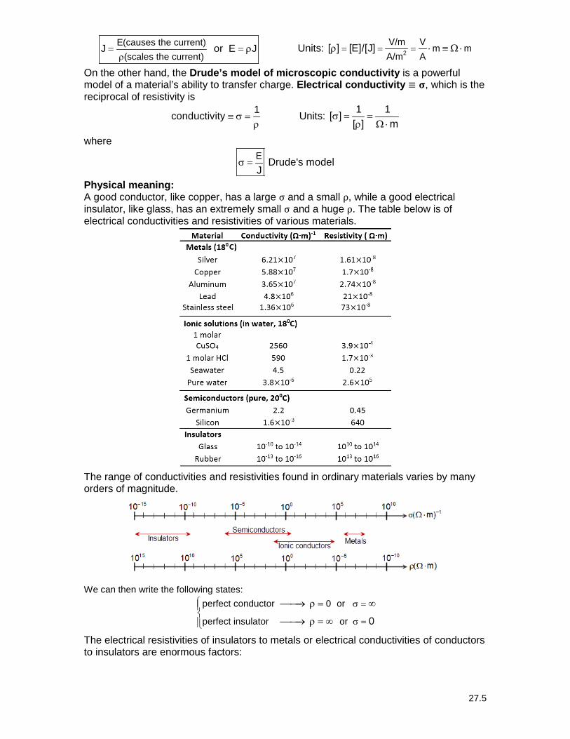
Physical meaning: A good conductor, like copper, has a large σ and a small ρ, while a good electrical insulator, like glass, has an extremely small σ and a huge ρ. The table below is of electrical conductivities and resistivities of various materials.
The range of conductivities and resistivities found in ordinary materials varies by many orders of magnitude.
We can then write the following states:
perfect conductor 0 or
perfect insulator or
0
σ =
σ =
→ ρ = ∞
→ ρ = ∞
The electrical resistivities of insulators to metals or electrical conductivities of conductors to insulators are enormous factors:
27.6
1422insulators
8conductors
10 1010−
ρ
ρ≈ ≈
This means that in general, insulators are 1022 more resistive than conductors. For example, the ratio of resistivities of wood to copper implies that electrons travel through a piece of copper with ease, they can hardly move at all through pieces of wood since wood is more resistive than copper by a factor of 1016. Stated similarly but different, the ratio of conductivities states exactly the same thing, conductors are 1022 better at conducting electrons than insulators are.
Electrical vs. Thermal Conductors Conductivity is the direct electrical analog of thermal conductivity: good conductors of electricity are also good conductors of heat (metals) whereas poor electrical conductors are also poor heat conductors (insulators). The reason for this is in a metal the free electrons that carry charge in electrical conductors also provide the principal mechanism for heat conduction. Therefore, we expect a correlation between electrical and thermal conductivity. However, there is a huge difference: heat conduction is just the collision of particles moving through a medium. Question: Why can’t we just heat up a wire to produce a current (or move charge)? It’s because of the σ-values! There is an enormous difference between σelectrical vs. σthermal. Suppose we have an electrical wire with insulation around it. Why doesn’t current flow through the insulation? One has to compare the ratio of electrical and thermal conductivities:
22 3metal metal
insulator insulatorelectrical thermal
10 vs. 10σ σ
σ σ
≈ ≈
The electrical ratio (≈1022) show an enormous difference metal and insulator conductivities, so electrically it is easy to confine electric currents to well-defined paths in copper wires in circuits since insulators greatly diminish current flow. On the other hand, the thermal ratio (≈103) shows just the opposite, that there is a slightly advantage for heat current to move through the copper wire than moving through an insulator. Therefore, it is impossible to confine heat currents to the same extent as electrical currents.
A material that obeys Ohm’s law reasonably well is called an ohmic (or linear) conductor, E constant OhmicJ
ρ = = →
When Ohm’s law is obeyed, ρ is constant and independent of the magnitude of the E-field, so E is directly proportional to J. However, if there are materials that show substantial departures from this, these materials are known as Non-ohmic (nonlinear) conductors (where J has some complicated dependence on E):
E constant NonohmicJ
ρ = ≠ →
For example, a diode has an exponential dependence on the voltage: 2/3J A V constant∝ ⋅ +
Applet EJSS Drift Velocity Model
MACROSCOPIC OHM’S LAW As I have been saying for some time now, the E-field pictures is complicated and want the potential picture instead. The relationship between resistivity and resistance and E-field and potential relationships are
VL ER and J iA R
∆ρρ→ = = → =
ρ
16wood
copper
10ρ
ρ≈ 22conductors
insulators
10σ
σ≈
27.7
It is straight forward to move from the microscopic picture to the macroscopic picture of Ohm’s law. This can be observed from
R L/ARAL
E J J EL V Ri=ρ
= ρ = ⋅ → = ∆ =
In summary, LV Ri where R A
∆ = = ρ
Applet EJSS Drift Velocity Model
Electrical resistance has four characteristics: area, length, material, and temperature (T)LRA
ρ=
1. Material Dependence: Conductors move charge whereas insulators do not conductors lower resistance
insulators higher resistance
→
→
2. Area Dependence: with water, as the diameter of the pipe increases, so does the amount of water that can flow through it. With electricity, conducting wires take the place of the pipe. As the cross-sectional area of the wire increases, so does the amount of electric current (number of electrons) that can flow through it.
Examples: Electrical fires Electrical fires are usually caused by having too much current in a smaller wire.
Why the difference in size between the outlet plug for a home clothes drier verses the outlet plug for a lamp?
DEMO Compare a power supply wire vs. lamp lead
3. Length Dependence: if the length of a wire is increased, does the number of collisions increase? Yes!
more collisions
less collisions
longer length smaller current higher resistance
shorter length higher current lower resistance
→ →
→ →
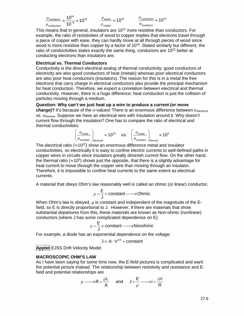
Interesting point: Cray-2 Example: Cray-2. No wire was longer than 6 inches. Why?
The Cray-2, installed in 1985 at LLNL, has 240,000 computer chips packed into the C-shaped cabinet. A liquid coolant must wash continuously over the circuits to dissipate heat that would otherwise melt the machine.
4. Temperature Dependence: If one heats up a metal and its temperature increases,
the resistance goes up. As the copper ions acquire KE from the heat energy, these
27.8
once stationary ions are now moving. It is now more likely that the electrons will collide more frequent with the copper ions, which results in a higher resistance and reduce current flow.
more collisions
less collisions
higher temperature higher resistance
lower temperature lower resistance
→
→
Examples: lightbulbs change brightness as they heat up; rear car windows and resistors. The resistivity of a metallic conductor nearly always increases with increasing temperature. Physically, as the temperature increases, the ions of the conductor vibrate with greater amplitude, making it more likely that a moving electron will collide with an ion. We find that resistivity is linear in temperature for small temperature regions according to
00 0 0
reference resistivity at T 20 C(T T )
thermal coefficient of resistivityρ
ρ = ρ ρ= = °
+ ⋅α − →α =
Example 27.2 A wire 4.00 m long and 6.00 mm in diameter has a resistance of 15.0 mΩ. A potential difference of 23.0 V is applied between the ends. (a) What is the current in the wire? (b) What is the magnitude of the current density? (c) Calculate the resistivity of the wire material and identify the material.
Solution a. Using the definition of Ohm’s law:
33
V 23Vi 1.53 10 A iR 15 10−
∆= = = × =
× Ω
b. The current density is 3
7 23 2
i 1.53 10J 5.41 10 A/m JA (3 10 m)
−
−
×= = = × =
π ⋅ ×
c. The resistivity is 3 3 2
8RA (15 10 ) (3.0 10 m) 10.6 10 mL 4.0m
− −−× Ω ⋅ π ⋅ ×
ρ = = = × Ω ⋅ = ρ
The material is platinum.
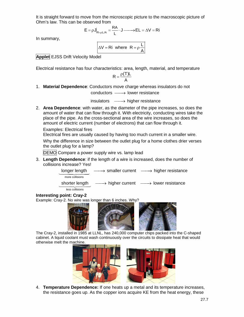
Application of Ohm’s Law – Electric Shock Nerves are on the order of 1μm, which is about the size of a spider web (1-4 μm). Because nerves are so thin, they cannot handle very much current.
Suppose that you are interested in trying to find out how much electric shock you can get out of a car battery (which has 12-volts). If you touch the two terminals of the car battery, the current path is then from your right hand to your left hand, that includes your heart in the circuit. How much electric shock you will receive will depend upon your electrical resistance. There are three cases.
27.9
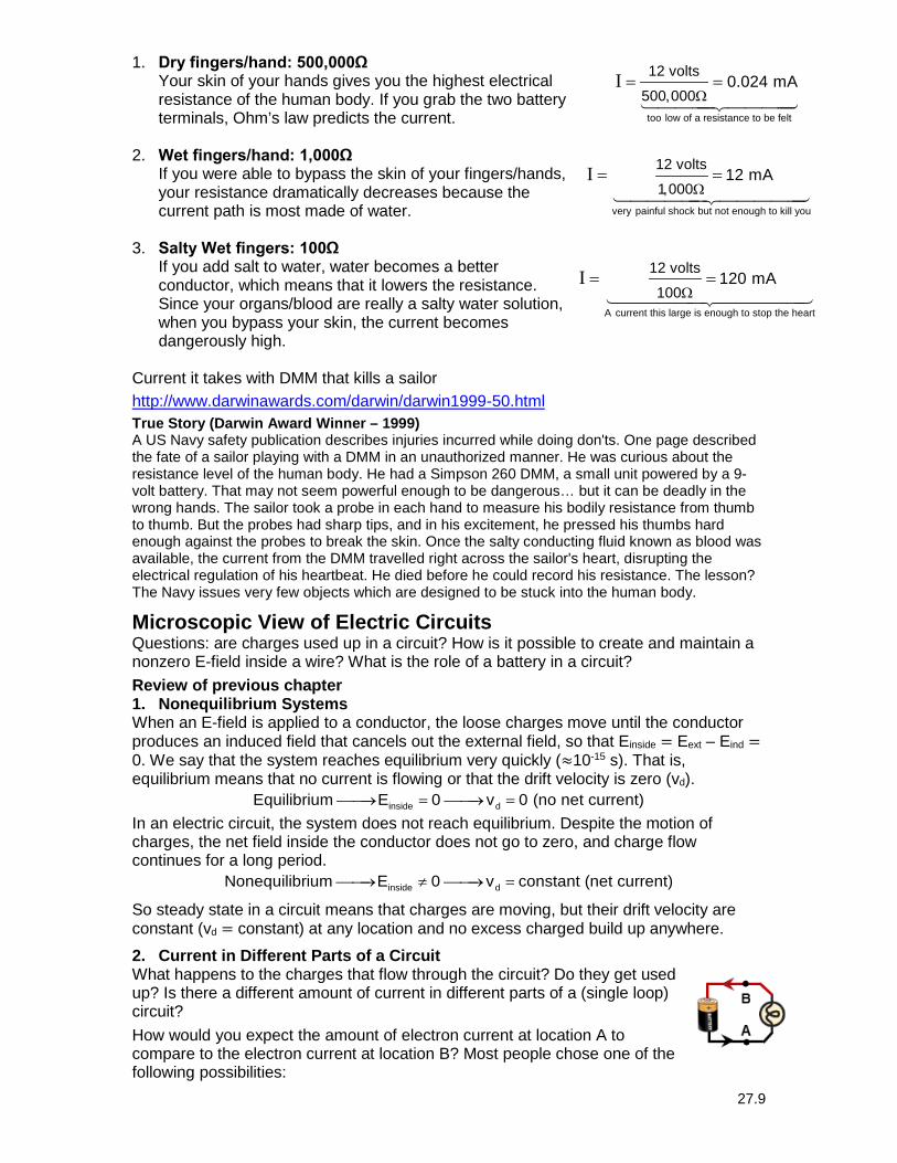
1. Dry fingers/hand: 500,000Ω Your skin of your hands gives you the highest electrical resistance of the human body. If you grab the two battery terminals, Ohm’s law predicts the current.
2. Wet fingers/hand: 1,000Ω
If you were able to bypass the skin of your fingers/hands, your resistance dramatically decreases because the current path is most made of water.
3. Salty Wet fingers: 100Ω
If you add salt to water, water becomes a better conductor, which means that it lowers the resistance. Since your organs/blood are really a salty water solution, when you bypass your skin, the current becomes dangerously high.
Current it takes with DMM that kills a sailor http://www.darwinawards.com/darwin/darwin1999-50.html True Story (Darwin Award Winner – 1999) A US Navy safety publication describes injuries incurred while doing don'ts. One page described the fate of a sailor playing with a DMM in an unauthorized manner. He was curious about the resistance level of the human body. He had a Simpson 260 DMM, a small unit powered by a 9-volt battery. That may not seem powerful enough to be dangerous… but it can be deadly in the wrong hands. The sailor took a probe in each hand to measure his bodily resistance from thumb to thumb. But the probes had sharp tips, and in his excitement, he pressed his thumbs hard enough against the probes to break the skin. Once the salty conducting fluid known as blood was available, the current from the DMM travelled right across the sailor's heart, disrupting the electrical regulation of his heartbeat. He died before he could record his resistance. The lesson? The Navy issues very few objects which are designed to be stuck into the human body.
Microscopic View of Electric Circuits Questions: are charges used up in a circuit? How is it possible to create and maintain a nonzero E-field inside a wire? What is the role of a battery in a circuit?
Review of previous chapter 1. Nonequilibrium Systems When an E-field is applied to a conductor, the loose charges move until the conductor produces an induced field that cancels out the external field, so that Einside = Eext – Eind = 0. We say that the system reaches equilibrium very quickly (≈10-15 s). That is, equilibrium means that no current is flowing or that the drift velocity is zero (vd).
inside dEquilibrium E 0 v 0 (no net current)→ = → = In an electric circuit, the system does not reach equilibrium. Despite the motion of charges, the net field inside the conductor does not go to zero, and charge flow continues for a long period.
inside dNonequilibrium E 0 v constant (net current)→ ≠ → =
So steady state in a circuit means that charges are moving, but their drift velocity are constant (vd = constant) at any location and no excess charged build up anywhere.
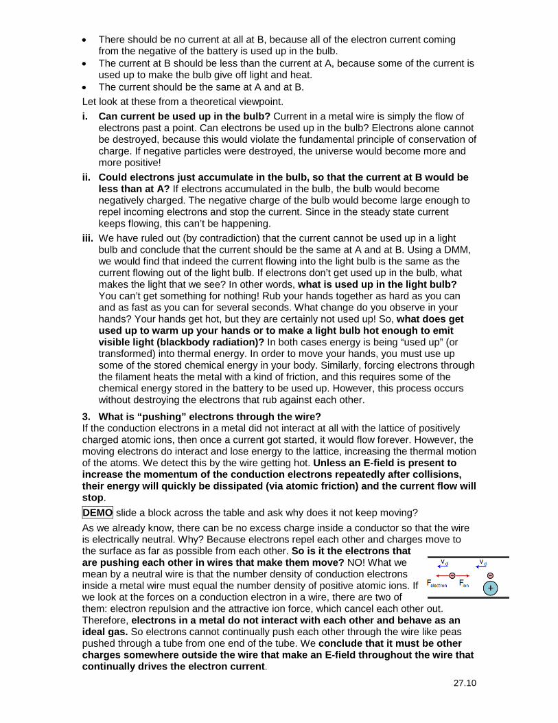
2. Current in Different Parts of a Circuit What happens to the charges that flow through the circuit? Do they get used up? Is there a different amount of current in different parts of a (single loop) circuit?
How would you expect the amount of electron current at location A to compare to the electron current at location B? Most people chose one of the following possibilities:
I
too low of a resistance to be felt
12 volts500,000
0.024 mAΩ
= =
I
very painful shock but not enough to kill you
12 volts1,000
12 mA Ω
= =
I
A current this large is enough to stop the heart
12 volts100
120 mA Ω
= =
27.10
• There should be no current at all at B, because all of the electron current coming from the negative of the battery is used up in the bulb.
• The current at B should be less than the current at A, because some of the current is used up to make the bulb give off light and heat.
• The current should be the same at A and at B.
Let look at these from a theoretical viewpoint.
i. Can current be used up in the bulb? Current in a metal wire is simply the flow of electrons past a point. Can electrons be used up in the bulb? Electrons alone cannot be destroyed, because this would violate the fundamental principle of conservation of charge. If negative particles were destroyed, the universe would become more and more positive!
ii. Could electrons just accumulate in the bulb, so that the current at B would be less than at A? If electrons accumulated in the bulb, the bulb would become negatively charged. The negative charge of the bulb would become large enough to repel incoming electrons and stop the current. Since in the steady state current keeps flowing, this can’t be happening.
iii. We have ruled out (by contradiction) that the current cannot be used up in a light bulb and conclude that the current should be the same at A and at B. Using a DMM, we would find that indeed the current flowing into the light bulb is the same as the current flowing out of the light bulb. If electrons don’t get used up in the bulb, what makes the light that we see? In other words, what is used up in the light bulb? You can’t get something for nothing! Rub your hands together as hard as you can and as fast as you can for several seconds. What change do you observe in your hands? Your hands get hot, but they are certainly not used up! So, what does get used up to warm up your hands or to make a light bulb hot enough to emit visible light (blackbody radiation)? In both cases energy is being “used up” (or transformed) into thermal energy. In order to move your hands, you must use up some of the stored chemical energy in your body. Similarly, forcing electrons through the filament heats the metal with a kind of friction, and this requires some of the chemical energy stored in the battery to be used up. However, this process occurs without destroying the electrons that rub against each other.
3. What is “pushing” electrons through the wire? If the conduction electrons in a metal did not interact at all with the lattice of positively charged atomic ions, then once a current got started, it would flow forever. However, the moving electrons do interact and lose energy to the lattice, increasing the thermal motion of the atoms. We detect this by the wire getting hot. Unless an E-field is present to increase the momentum of the conduction electrons repeatedly after collisions, their energy will quickly be dissipated (via atomic friction) and the current flow will stop.
DEMO slide a block across the table and ask why does it not keep moving?
As we already know, there can be no excess charge inside a conductor so that the wire is electrically neutral. Why? Because electrons repel each other and charges move to the surface as far as possible from each other. So is it the electrons that are pushing each other in wires that make them move? NO! What we mean by a neutral wire is that the number density of conduction electrons inside a metal wire must equal the number density of positive atomic ions. If we look at the forces on a conduction electron in a wire, there are two of them: electron repulsion and the attractive ion force, which cancel each other out. Therefore, electrons in a metal do not interact with each other and behave as an ideal gas. So electrons cannot continually push each other through the wire like peas pushed through a tube from one end of the tube. We conclude that it must be other charges somewhere outside the wire that make an E-field throughout the wire that continually drives the electron current.
27.11
How big does an E-field have to be to push electrons through a wire? For copper, Ecopper ≈1 V/m. 4. Current and E-field To explain the role of the E-field in a wire, I introduce KCL, which is not a fundamental law but a consequence of conservation of charge and definition of steady state.
Kirchhoff’s Current Law (KCL): the current entering a node in a circuit is equal to the current leaving that node.
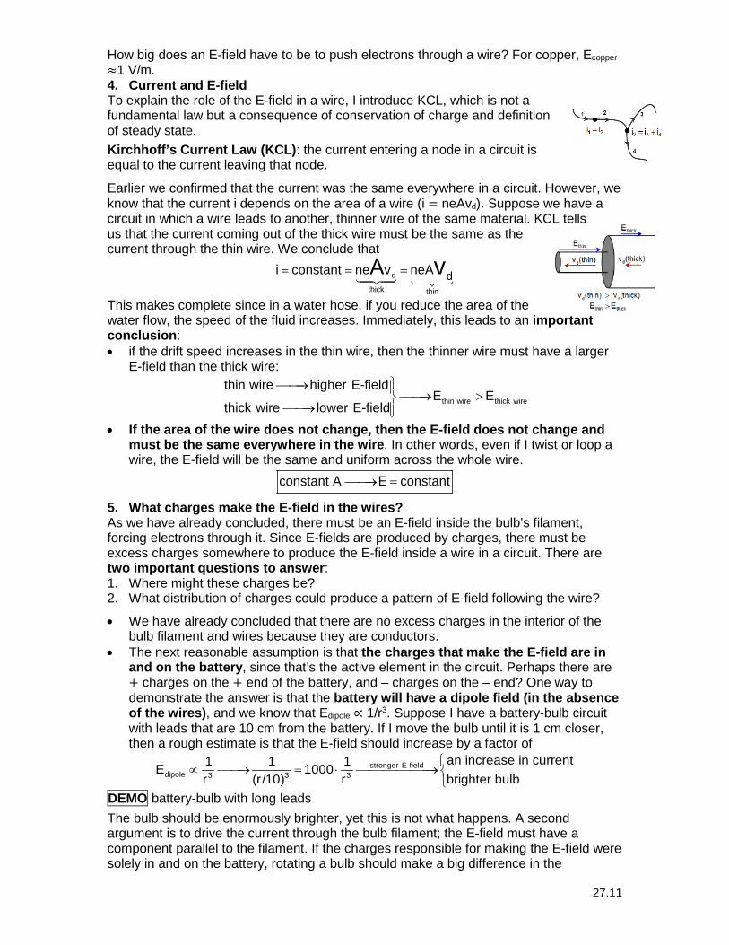
Earlier we confirmed that the current was the same everywhere in a circuit. However, we know that the current i depends on the area of a wire (i = neAvd). Suppose we have a circuit in which a wire leads to another, thinner wire of the same material. KCL tells us that the current coming out of the thick wire must be the same as the current through the thin wire. We conclude that d
thick thin
di constant ne v neAA v= = =
This makes complete since in a water hose, if you reduce the area of the water flow, the speed of the fluid increases. Immediately, this leads to an important conclusion: • if the drift speed increases in the thin wire, then the thinner wire must have a larger
E-field than the thick wire:
thin wire thick wire
thin wire higher E-fieldE E
thick wire lower E-field
→ → >→
• If the area of the wire does not change, then the E-field does not change and must be the same everywhere in the wire. In other words, even if I twist or loop a wire, the E-field will be the same and uniform across the whole wire.
constant A E constant→ =
5. What charges make the E-field in the wires? As we have already concluded, there must be an E-field inside the bulb’s filament, forcing electrons through it. Since E-fields are produced by charges, there must be excess charges somewhere to produce the E-field inside a wire in a circuit. There are two important questions to answer: 1. Where might these charges be? 2. What distribution of charges could produce a pattern of E-field following the wire?
• We have already concluded that there are no excess charges in the interior of the bulb filament and wires because they are conductors.
• The next reasonable assumption is that the charges that make the E-field are in and on the battery, since that’s the active element in the circuit. Perhaps there are + charges on the + end of the battery, and – charges on the – end? One way to demonstrate the answer is that the battery will have a dipole field (in the absence of the wires), and we know that Edipole ∝ 1/r3. Suppose I have a battery-bulb circuit with leads that are 10 cm from the battery. If I move the bulb until it is 1 cm closer, then a rough estimate is that the E-field should increase by a factor of
stronger E-fielddipole 3 3 3
an increase in current1 1 1E 1000r (r/10) r brighter bulb
∝ → = ⋅ →
DEMO battery-bulb with long leads
The bulb should be enormously brighter, yet this is not what happens. A second argument is to drive the current through the bulb filament; the E-field must have a component parallel to the filament. If the charges responsible for making the E-field were solely in and on the battery, rotating a bulb should make a big difference in the
27.12
brightness (or even make the bulb go out), but this doesn’t happen. We concluded that charges in and on the battery cannot be the only contributors to the E-field in the bulb filament. There must be other charges somewhere else (and these charges can’t be inside the wires or filament). This is deeply puzzling.
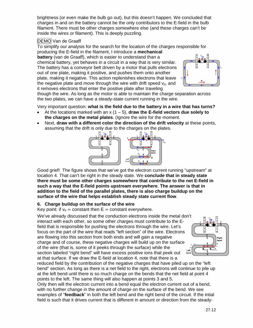
DEMO Van de Graaff To simplify our analysis for the search for the location of the charges responsible for producing the E-field in the filament, I introduce a mechanical battery (van de Graaff), which is easier to understand than a chemical battery, yet behaves in a circuit in a way that is very similar. The battery has a conveyor belt driven by a motor that pulls electrons out of one plate, making it positive, and pushes them onto another plate, making it negative. This action replenishes electrons that leave the negative plate and move through the wire with drift speed vd, and it removes electrons that enter the positive plate after traveling though the wire. As long as the motor is able to maintain the charge separation across the two plates, we can have a steady-state current running in the wire.
Very important question: what is the field due to the battery in a wire that has turns? • At the locations marked with an x (1 – 5), draw the E-field vectors due solely to
the charges on the metal plates. (Ignore the wire for the moment. • Next, draw with a different color the direction of the drift velocity at these points,
assuming that the drift is only due to the charges on the plates.
Good grief! The figure shows that we’ve got the electron current running “upstream” at location 4. That can’t be right in the steady state. We conclude that in steady state there must be some other charges somewhere that contribute to the net E-field in such a way that the E-field points upstream everywhere. The answer is that in addition to the field of the parallel plates, there is also charge buildup on the surface of the wire that helps establish steady state current flow.
6. Charge buildup on the surface of the wire Key point: if vd = constant then E = constant everywhere.
We’ve already discussed that the conduction electrons inside the metal don’t interact with each other, so some other charges must contribute to the E-field that is responsible for pushing the electrons through the wire. Let’s focus on the part of the wire that reads “left section” of the wire. Electrons are flowing into this section from both ends and will gain a negative charge and of course, these negative charges will build up on the surface of the wire (that is, some of it peeks through the surface) while the section labeled “right bend” will have excess positive ions that peek out at that surface. If we draw the E-field at location 4, note that there is a reduced field by the contribution of the negative charges that have piled up on the “left bend” section. As long as there is a net field to the right, electrons will continue to pile up at the left bend until there is so much charge on the bends that the net field at point 4 points to the left. The same thing will also happen at points 3 and 5. Only then will the electron current into a bend equal the electron current out of a bend, with no further change in the amount of charge on the surface of the bend. We see examples of “feedback” in both the left bend and the right bend of the circuit. If the intial field is such that it drives current that is different in amount or direction from the steady-
27.13
state current, surface charge automatically builds up in such a way as to alter the current to be more like the steady-state current. Moreover, once the steady state is established, there is “negative feedback”: any deviation away from the steady state will produce a change in the surface charge that tends to restore the steady-state conditions. In other words, steady state is the lowest possible energy for this system.
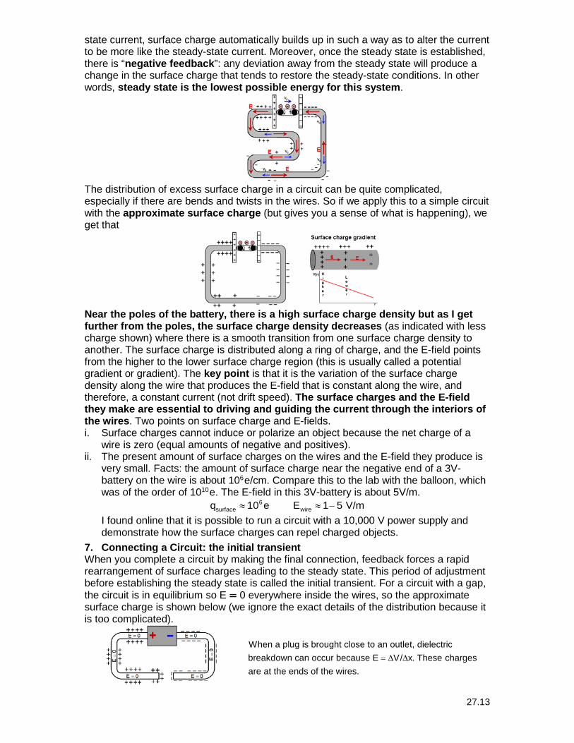
The distribution of excess surface charge in a circuit can be quite complicated, especially if there are bends and twists in the wires. So if we apply this to a simple circuit with the approximate surface charge (but gives you a sense of what is happening), we get that
Near the poles of the battery, there is a high surface charge density but as I get further from the poles, the surface charge density decreases (as indicated with less charge shown) where there is a smooth transition from one surface charge density to another. The surface charge is distributed along a ring of charge, and the E-field points from the higher to the lower surface charge region (this is usually called a potential gradient or gradient). The key point is that it is the variation of the surface charge density along the wire that produces the E-field that is constant along the wire, and therefore, a constant current (not drift speed). The surface charges and the E-field they make are essential to driving and guiding the current through the interiors of the wires. Two points on surface charge and E-fields. i. Surface charges cannot induce or polarize an object because the net charge of a
wire is zero (equal amounts of negative and positives). ii. The present amount of surface charges on the wires and the E-field they produce is
very small. Facts: the amount of surface charge near the negative end of a 3V-battery on the wire is about 106
e/cm. Compare this to the lab with the balloon, which was of the order of 1010
e. The E-field in this 3V-battery is about 5V/m. 6
surface wireq 10 e E 1 5 V/m≈ ≈ − I found online that it is possible to run a circuit with a 10,000 V power supply and demonstrate how the surface charges can repel charged objects.
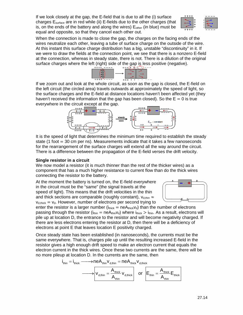
7. Connecting a Circuit: the initial transient When you complete a circuit by making the final connection, feedback forces a rapid rearrangement of surface charges leading to the steady state. This period of adjustment before establishing the steady state is called the initial transient. For a circuit with a gap, the circuit is in equilibrium so E = 0 everywhere inside the wires, so the approximate surface charge is shown below (we ignore the exact details of the distribution because it is too complicated).
When a plug is brought close to an outlet, dielectricbreakdown can occur because E V/ x. These chargesare at the ends of the wires.
= ∆ ∆
27.14
If we look closely at the gap, the E-field that is due to all the (i) surface charges Esurface are in red while (ii) E-fields due to the other charges (that is, on the ends of the battery and along the wires) Eother (in blue) must be equal and opposite, so that they cancel each other out.
When the connection is made to close the gap, the charges on the facing ends of the wires neutralize each other, leaving a tube of surface charge on the outside of the wire. At this instant this surface charge distribution has a big, unstable “discontinuity” in it. If we were to draw the fields at the connection point, we see that there is a nonzero E-field at the connection, whereas in steady state, there is not. There is a dilution of the original surface charges where the left (right) side of the gap is less positive (negative).
If we zoom out and look at the whole circuit, as soon as the gap is closed, the E-field on the left circuit (the circled area) travels outwards at approximately the speed of light, so the surface charges and the E-field at distance locations haven’t been affected yet (they haven’t received the information that the gap has been closed). So the E = 0 is true everywhere in the circuit except at the gap.
It is the speed of light that determines the minimum time required to establish the steady state (1 foot = 30 cm per ns). Measurements indicate that it takes a few nanoseconds for the rearrangement of the surface charges will extend all the way around the circuit. There is a difference between the propagation of the E-field verses the drift velocity.
Single resistor in a circuit We now model a resistor (it is much thinner than the rest of the thicker wires) as a component that has a much higher resistance to current flow than do the thick wires connecting the resistor to the battery.
At the moment the battery is turned on, the E-field everywhere in the circuit must be the “same” (the signal travels at the speed of light). This means that the drift velocities in the thin and thick sections are comparable (roughly constant), vd,thin ≈ vd,thick = vd. However, number of electrons per second trying to enter the resistor is a larger number (ithick = neAthickvd) than the number of electrons passing through the resistor (ithin = neAthinvd) where ithick > ithin. As a result, electrons will pile up at location D, the entrance to the resistor and will become negativity charged. If there are less electrons entering the resistor at D, then there will be a deficiency of electrons at point E that leaves location E positivity charged.
Once steady state has been established (in nanoseconds), the currents must be the same everywhere. That is, charges pile up until the resulting increased E-field in the resistor gives a high enough drift speed to make an electron current that equals the electron current in the thick wires. Once these two currents are the same, there will be no more pileup at location D. In the currents are the same, then
thin thick thin d,thin thick d,thick
thick thickd,thin d,thick thin thick
thin thin
i i neA v neA v
A A v v or E EA A
= → =
→ = =
27.15
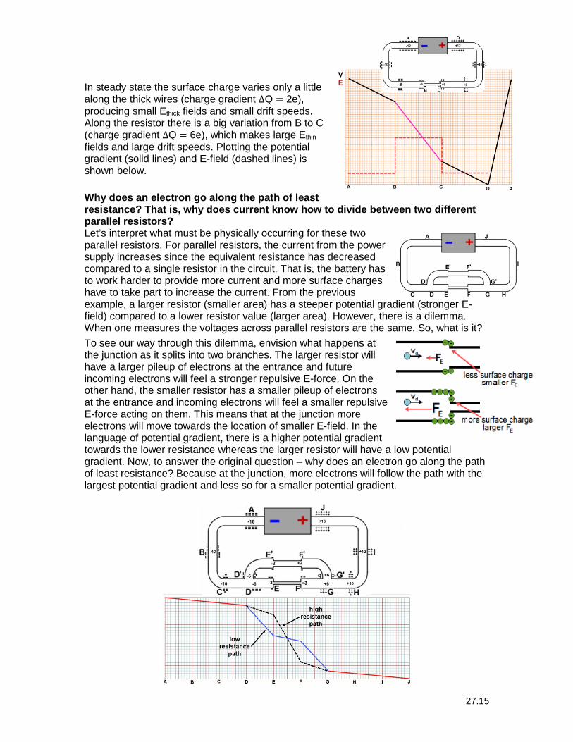
In steady state the surface charge varies only a little along the thick wires (charge gradient ∆Q = 2e), producing small Ethick fields and small drift speeds. Along the resistor there is a big variation from B to C (charge gradient ∆Q = 6e), which makes large Ethin fields and large drift speeds. Plotting the potential gradient (solid lines) and E-field (dashed lines) is shown below.
Why does an electron go along the path of least resistance? That is, why does current know how to divide between two different parallel resistors? Let’s interpret what must be physically occurring for these two parallel resistors. For parallel resistors, the current from the power supply increases since the equivalent resistance has decreased compared to a single resistor in the circuit. That is, the battery has to work harder to provide more current and more surface charges have to take part to increase the current. From the previous example, a larger resistor (smaller area) has a steeper potential gradient (stronger E-field) compared to a lower resistor value (larger area). However, there is a dilemma. When one measures the voltages across parallel resistors are the same. So, what is it?
To see our way through this dilemma, envision what happens at the junction as it splits into two branches. The larger resistor will have a larger pileup of electrons at the entrance and future incoming electrons will feel a stronger repulsive E-force. On the other hand, the smaller resistor has a smaller pileup of electrons at the entrance and incoming electrons will feel a smaller repulsive E-force acting on them. This means that at the junction more electrons will move towards the location of smaller E-field. In the language of potential gradient, there is a higher potential gradient towards the lower resistance whereas the larger resistor will have a low potential gradient. Now, to answer the original question – why does an electron go along the path of least resistance? Because at the junction, more electrons will follow the path with the largest potential gradient and less so for a smaller potential gradient.


![Path of Most Resistance [Exhibition Catalogue] · The Path of Most Resistance OCAD Professional Gallery June 26 to September 13, 2009 about the artists London’s Alexis Harding has](https://img.pdfslide.net/doc/110x75/5fb159a0567318051e2300e7/path-of-most-resistance-exhibition-catalogue-the-path-of-most-resistance-ocad.jpg)


![[Robert Fritz] the Path of Least Resistance for Ma(BookSee.org)](https://img.pdfslide.net/doc/110x75/563db92b550346aa9a9ab842/robert-fritz-the-path-of-least-resistance-for-mabookseeorg.jpg)

